EP2773171A2 - Electronic device - Google Patents
Electronic device Download PDFInfo
- Publication number
- EP2773171A2 EP2773171A2 EP13185691.6A EP13185691A EP2773171A2 EP 2773171 A2 EP2773171 A2 EP 2773171A2 EP 13185691 A EP13185691 A EP 13185691A EP 2773171 A2 EP2773171 A2 EP 2773171A2
- Authority
- EP
- European Patent Office
- Prior art keywords
- heat
- electronic device
- dissipation sheet
- heat sink
- heat dissipation
- Prior art date
- Legal status (The legal status is an assumption and is not a legal conclusion. Google has not performed a legal analysis and makes no representation as to the accuracy of the status listed.)
- Granted
Links
Images





Classifications
-
- H—ELECTRICITY
- H05—ELECTRIC TECHNIQUES NOT OTHERWISE PROVIDED FOR
- H05K—PRINTED CIRCUITS; CASINGS OR CONSTRUCTIONAL DETAILS OF ELECTRIC APPARATUS; MANUFACTURE OF ASSEMBLAGES OF ELECTRICAL COMPONENTS
- H05K7/00—Constructional details common to different types of electric apparatus
- H05K7/20—Modifications to facilitate cooling, ventilating, or heating
- H05K7/2039—Modifications to facilitate cooling, ventilating, or heating characterised by the heat transfer by conduction from the heat generating element to a dissipating body
- H05K7/20436—Inner thermal coupling elements in heat dissipating housings, e.g. protrusions or depressions integrally formed in the housing
- H05K7/20445—Inner thermal coupling elements in heat dissipating housings, e.g. protrusions or depressions integrally formed in the housing the coupling element being an additional piece, e.g. thermal standoff
- H05K7/20472—Sheet interfaces
-
- H—ELECTRICITY
- H01—ELECTRIC ELEMENTS
- H01F—MAGNETS; INDUCTANCES; TRANSFORMERS; SELECTION OF MATERIALS FOR THEIR MAGNETIC PROPERTIES
- H01F27/00—Details of transformers or inductances, in general
- H01F27/08—Cooling; Ventilating
-
- H—ELECTRICITY
- H05—ELECTRIC TECHNIQUES NOT OTHERWISE PROVIDED FOR
- H05K—PRINTED CIRCUITS; CASINGS OR CONSTRUCTIONAL DETAILS OF ELECTRIC APPARATUS; MANUFACTURE OF ASSEMBLAGES OF ELECTRICAL COMPONENTS
- H05K7/00—Constructional details common to different types of electric apparatus
- H05K7/20—Modifications to facilitate cooling, ventilating, or heating
- H05K7/2089—Modifications to facilitate cooling, ventilating, or heating for power electronics, e.g. for inverters for controlling motor
- H05K7/209—Heat transfer by conduction from internal heat source to heat radiating structure
Definitions
- the present invention relates to an electronic device.
- a flat heat dissipation sheet 2 is provided between the upper surface of the heat generating component 1 and a flat metal frame 3 (which may also be constituted by a metal casing) of the electronic device as shown in Fig. 8 , thus, heat generated by the heat generating component 1 is transferred to the metal frame 3 via the heat dissipation sheet 2 and then discharged to atmosphere, wherein the heat dissipation sheet 2 constitutes a conventional heat sink structure.
- the contact area between the heat dissipation sheet 2 and the metal frame 3 gets smaller and heat transferred to the heat dissipation sheet 2 from the heat generating component 1 may not be efficiently transferred to the metal frame 3, and thus, it is more difficult to efficiently cool the heat generating component 1.
- the present invention has been devised to solve the problems described above, and an object thereof is to provide an electronic device configured to efficiently cool a heat generating component with a complex shape.
- the electronic device is provided with a substrate, a heat generating device, a heat sink structure comprising a heat sink and deformable heat dissipation sheets, as well as a flat metal frame, the heat generating component is provided on the substrate, the heat dissipation sheet is in areal contact with at least part of the outer surface on one side of the heat generating component, the outer surface being opposite to the substrate, the heat sink covers a part of the heat generating component with the heat dissipation sheet interposed therebetween, and further, the heat sink is attached to (or provided on) the metal frame, and the outer surface of the heating component is a non-flat (uneven) surface.
- the electronic device as described in the technical solution 2 is as described in technical solution 1, wherein the heat sink comprises two side walls and a flat main body part attached to the metal frame, the two side walls extend towards one side opposite to the metal frame from two opposite ends of the main body part, and the main body part and the two side walls abut against the outer surface with the heat dissipation sheet interposed therebetween.
- the electronic device as described in the technical solution 3 is as described according in technical solution 2, wherein the side walls are curved or flat and define a specified angle with the main body part.
- the electronic device as described in the technical solution 4 is as described technical solution 2 or 3, wherein the end parts of the side walls are curved to form curved parts, and the curved parts abut against the outer surface with the heat dissipation sheet interposed therebetween.
- the electronic device as described in the technical solution 5 is as described in any of technical solutions 2 to 4, wherein one or more than two screws are attached to the main body part of the heat sink.
- the electronic device as described in the technical solution 6 is as described in any of technical solutions 1 to 5, wherein when two or more heat generating components are provided, the quantity of the heat sink is equal to or smaller than that of the heat generating components, and one or more heat dissipation sheet is provided.
- the electronic device as described in the technical solution 7 is as described in any of technical solutions 1 to 6, wherein the heat sink is made of a material with high heat conductivity.
- the electronic device as described in the technical solution 8 is as described in any of technical solutions 1 to 7, wherein the electronic device is a switching power supply, and the heat generating component is a transformer.
- the electronic device as described in the technical solution 8 is described according to technical solution 9, wherein the transformer is provided with a base mounted on the substrate and a heat generating part mounted in the base, the heat generating part is provided with a protruding part configured to protrude towards one side opposite to the substrate from the base, and the heat dissipation sheet is in areal contact with the outer surface of the protruding part.
- the electronic device as described in the technical solution 9 is described according to technical solution 10, wherein the outer surface of the producing part is a curved surface, or a surface including a curved surface and a flat surface, or a surface including two or more flat surfaces.
- the contact area between the heat sink structure and the heat generating component may get larger, thereby efficiently cooling the heat generating component.
- a switching power supply is given as an example, but the electronic device is not limited thereto, and may also be another device with heat generating components.
- a transformer is given as an example, however, the heat generating component is not limited thereto, and any component configured to generate heat while operating may be applicable to the heat sink structure of the present embodiment.
- Fig. 1 is a schematic perspective view illustrating a state where a transformer in a switching power supply is separated from the heat dissipation sheet according to this embodiment.
- Fig. 2 is a schematic perspective view illustrating a state where the heat dissipation sheet is provided on the transformer in the switching power supply according to this embodiment.
- Fig. 3 is a schematic sectional view illustrating a state where the heat dissipation sheet is provided on the transformer.
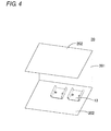
- Fig. 4 is a schematic perspective view illustrating a shell installed (provided) with the heat sink of the switching power supply according to this embodiment.
- Fig. 5 is a schematic perspective view illustrating the heat sink in the heat sink structure.
- Fig. 6 is a sectional view of the heat sink. Figs.
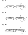
- FIG. 7A to 7C are schematic sectional views illustrating a state where the transformer is in contact with the heat sink.
- Fig. 8 is a sectional view illustrating a heat generating component installed with a conventional heat sink structure.
- Fig. 9 is a sectional view illustrating the heat generating component installed with a conventional heat sink structure.
- the switching power supply provided by the present embodiment is provided with a substrate 10 and a shell 20. Further, as shown in Fig. 1 , various heat generating components, such as a transformer 11, are provided on the upper surface of the substrate 10, and the transformer 11 is provided with a base 111 and a core part 112 provided on the base 111 and working as a heat generating part, and furthermore, the core part 112 is provided with a protruding part 113 configured to protrude towards one side opposite to the substrate 10 from the base 111.
- various heat generating components such as a transformer 11
- the transformer 11 is provided with a base 111 and a core part 112 provided on the base 111 and working as a heat generating part, and furthermore, the core part 112 is provided with a protruding part 113 configured to protrude towards one side opposite to the substrate 10 from the base 111.
- the upper surface of the protruding part 113 of the core part 112 is called "the upper surface of the transformer" (the outer surface of one side of the transformer which is opposite to the substrate 10).
- the upper surface of the transformer 11 is a curved surface rather than a flat surface.
- the shape of the upper surface of the transformer 11 is not limited thereto, the upper surface may be a surface including a curved surface and a flat surface, or a surface including two or more flat surfaces.
- two transformers 11 are illustrated, but the quantity of the transformers 11 is not limited thereto, one or more than two transformers may also be provided.
- the transformer 11 is provided with the base 111, but it may alternatively not be provided with a base 111, and in this case a cooling effect of the transformer is the same as that of the transformer with the base.
- the heat dissipation sheet 12 may approximately and appropriately deform in correspondence with the shape of a protruding part 113 of the transformer 11.
- the heat dissipation sheet 12 is flexible, when the upper surface of the protruding part 113 of the transformer 11 has a complex shape, as shown in Fig.3 , the heat dissipation sheet 12 is only in contact with the top of the protruding part 13 of the transformer 11 rather than coming into sufficient contact with the side surface of the protruding part 113 of the transformer 11. Under such circumstances, although no graphical representation is provided, if the deformed heat dissipation sheet 12 comes into direct contact with a flat metal frame as shown in Fig.8 , the heat dissipation sheet 12 may be only in partial contact with the metal frame, which may seriously influence the cooling effect of the transformer.
- a shell 20 is formed by bending two ends of a flat metal plate towards the same direction, and comprises a main body part 201 and two side walls 202 vertical to the main body part 201.
- Two heat sinks 13 are provided on the inner surface of one side wall 202 (i,e., the metal frame in the present embodiment) of the shell 20, but alternatively, only one heat sink 13 may be mounted. That is, according to the present embodiment, the number of heat sinks 13 may be the same as, or alternatively, may be smaller than that of the transformers 11.
- the heat sinks 13 each have a shape corresponding to that of the transformers 11. According to the present embodiment, each heat sink 13 is formed by bending two ends of the flat metal plate made of materials, such as aluminum, with high heat conductivity.
- the heat sink 13 comprises a flat main body part 131 and two side walls 132 vertical to the main body part 131. Under the circumstance that the heat sink 13 is provided on the inner surface of the side wall 202, the two side walls 132 extend from two opposite ends of the main body part 131 to one side opposite to the side wall 202.
- the main body part 131 and the two side walls 132 of the heat sink 13 abut against the protruding part 113 of the transformer 11 with the heat dissipation sheet 12 interposed therebetween, so that the heat dissipation sheet 12 may be in areal contact with the outer surface of one side of the protruding part 113, which is opposite to the substrate 10.
- the side wall 132 may also be further curved to form a curved part 133 as shown in Fig. 5 , and a curved part 134 is in areal contact with the side wall 132, or it may also be separated from the side wall 132 by a certain distance.
- the contact area between the heat dissipation sheet 12 and the protruding part 113 of the transformer 11 may be increased, and the contact area between the heat dissipation sheet 12 and the heat sink 13 may be increased.
- the main body part 131 is flat so that the effective contact area between the heat sink 13 fixed on the shell 20 and the shell 20 is ensured, and accordingly, the cooling effect of the transformer 11 may be improved.
- the heat sink 13 may use other shapes, for instance, the flat side wall 132 may not be configured to be vertical to the main body part 131, or the flat side wall 132 is made into a curved shape and the like.
- the contact area between the side wall 132 and the heat dissipation sheet 12 is further increased by enabling the side wall 132 to form a specified angle with the main body part 131, thus, the contact area of the side wall 132 and the heat dissipation sheet 12 is increased, thereby further increasing the contact area between the heat dissipation sheet 12, and the protruding part 113 of the transformer 11, and a heat sink may be configured to any shape as long as the contact area between the heat dissipation sheet 12 and the protruding part 113 of the transformer 11 is favorably increased.
- the flat main body part 131 of the heat sink 13 is provided with two screw holes and is fixed on the inner surface of a side wall 202 of the shell 20 via two screws so as to prevent the efficiency of heat transfer from the heat sink 13 to the shell 20 from being reduced by the contact area between the heat sink 13 and the side wall 202 getting smaller when the heat sink 13 inclines.
- the main body part 131 may also be provided with three or more screw holes configured for installation of three or more screws, and thus, the heat sink 13 is fixed on the side wall 202 more stably.
- the main body part 131 may also be provided with one screw hole configured to installation of one screw.
- a mounting method for mounting the substrate 10 installed with the transformer 11 to the shell 20 is described as below.
- the substrate 10 installed with the transformer 11 is inserted into the shell 20 as shown in Fig. 4 , in a direction approximately parallel to the side wall 202 of the shell 20.
- the transformer 11 is arranged to be opposite to the heat sink 13 provided on the side wall 202; furthermore, the substrate 10 is pushed towards the side wall 202 installed with the heat sink 13 (i.e., the metal frame of the present embodiment), so that a protruding part 113 of the transformer 11 enters a space between the two side walls 132 of the heat sink 13, thereby enabling the heat sink 13 to cover a part of transformer 11; and finally, as shown in Fig.
- the main body part 131 of the heat sink 13 abuts against the top of the protruding part 113 of the transformer 11 with the heat dissipation sheet 12 interposed therebetween, two side walls 132 abut against the side surface of the protruding part 131 of the transformer 11 via the heat dissipation sheet 12, and thus, the heat dissipation sheet 12 is in areal contact with the protruding part 113 of the transformer 11.
- area contact also referred to as "surface contact” refers to the case that the contact region extends over a certain surface area, as opposed to "point contact” or “linear contact", where the contact is substantially point-shaped or line-shaped. Accordingly, the contact area between the heat dissipation sheet 10 and the protruding part of the transformer 11 is increased, and the cooling effect on the transformer 11 is improved.
- FIG. 7B a schematic sectional view showing the state when a heat sink 13 of another embodiment is in contact with the protruding part 113 with the heat dissipation sheet 12 interposed therebetween is disclosed in Fig. 7B .
- the contact area between the heat sink 13 and the heat dissipation sheet 12 may be further increased by using a curved part 133 of the heat sink 13 as shown in Fig. 7B , and the cooling effect on the transformer 11 may be improved.
- two heat sinks 13 as shown in Fig. 7A may be formed in one piece, and the heat dissipation sheet 12 is pushed by the heat sink 13 as shown in Fig. 7C .
- the heat dissipation sheet 12 is only in areal contact with a part of the outer surface of the protruding part 113 if the protruding part 113 is not shaped as a regular curved surface, and the contact area between the heat dissipation sheet 12 and the protruding part 113 may also be increased by adopting the heat sink 13 described above.
- the contact area between the heat sink structure and the heat generating component may also get larger even if the heat generating component has a complex shape, and the heat generating component may be cooled efficiently.
Landscapes
- Engineering & Computer Science (AREA)
- Microelectronics & Electronic Packaging (AREA)
- Physics & Mathematics (AREA)
- Thermal Sciences (AREA)
- Power Engineering (AREA)
- Cooling Or The Like Of Electrical Apparatus (AREA)
- Cooling Or The Like Of Semiconductors Or Solid State Devices (AREA)
Abstract
Description
- The present invention relates to an electronic device.
- Previously, when a heat generating component 1 in an electronic device is cooled, a flat
heat dissipation sheet 2 is provided between the upper surface of the heat generating component 1 and a flat metal frame 3 (which may also be constituted by a metal casing) of the electronic device as shown inFig. 8 , thus, heat generated by the heat generating component 1 is transferred to themetal frame 3 via theheat dissipation sheet 2 and then discharged to atmosphere, wherein theheat dissipation sheet 2 constitutes a conventional heat sink structure. However, as shown inFig. 9 , when the upper surface of the heat generating component 1 is, for example, a curved surface rather than a flat surface, although the flatheat dissipation sheet 2 has a certain flexibility, it is only in contact with the top of the curved surface, therefore the contact area between theheat dissipation sheet 2 and the heat generating component 1 gets smaller, thus, it is difficult to efficiently cool the heat generating component 1. - Further, since only the top of the deformed
heat dissipation sheet 2 is in contact with theflat metal frame 3, the contact area between theheat dissipation sheet 2 and themetal frame 3 gets smaller and heat transferred to theheat dissipation sheet 2 from the heat generating component 1 may not be efficiently transferred to themetal frame 3, and thus, it is more difficult to efficiently cool the heat generating component 1. - The present invention has been devised to solve the problems described above, and an object thereof is to provide an electronic device configured to efficiently cool a heat generating component with a complex shape.
- In accordance with one aspect of the present invention, in an electronic device is described according to technical solution 1,
the electronic device is provided with a substrate, a heat generating device, a heat sink structure comprising a heat sink and deformable heat dissipation sheets, as well as a flat metal frame, the heat generating component is provided on the substrate, the heat dissipation sheet is in areal contact with at least part of the outer surface on one side of the heat generating component, the outer surface being opposite to the substrate, the heat sink covers a part of the heat generating component with the heat dissipation sheet interposed therebetween, and further, the heat sink is attached to (or provided on) the metal frame, and the outer surface of the heating component is a non-flat (uneven) surface. - The electronic device as described in the
technical solution 2 is as described in technical solution 1, wherein
the heat sink comprises two side walls and a flat main body part attached to the metal frame, the two side walls extend towards one side opposite to the metal frame from two opposite ends of the main body part, and the main body part and the two side walls abut against the outer surface with the heat dissipation sheet interposed therebetween. - The electronic device as described in the
technical solution 3 is as described according intechnical solution 2, wherein
the side walls are curved or flat and define a specified angle with the main body part. - The electronic device as described in the technical solution 4 is as described
technical solution
the end parts of the side walls are curved to form curved parts, and the curved parts abut against the outer surface with the heat dissipation sheet interposed therebetween. - The electronic device as described in the technical solution 5 is as described in any of
technical solutions 2 to 4, wherein
one or more than two screws are attached to the main body part of the heat sink. - The electronic device as described in the technical solution 6 is as described in any of technical solutions 1 to 5, wherein
when two or more heat generating components are provided, the quantity of the heat sink is equal to or smaller than that of the heat generating components, and one or more heat dissipation sheet is provided. - The electronic device as described in the technical solution 7 is as described in any of technical solutions 1 to 6, wherein
the heat sink is made of a material with high heat conductivity. - The electronic device as described in the technical solution 8 is as described in any of technical solutions 1 to 7, wherein
the electronic device is a switching power supply, and the heat generating component is a transformer. - The electronic device as described in the technical solution 8 is described according to technical solution 9, wherein
the transformer is provided with a base mounted on the substrate and a heat generating part mounted in the base, the heat generating part is provided with a protruding part configured to protrude towards one side opposite to the substrate from the base, and the heat dissipation sheet is in areal contact with the outer surface of the protruding part. - The electronic device as described in the technical solution 9 is described according to
technical solution 10, wherein
the outer surface of the producing part is a curved surface, or a surface including a curved surface and a flat surface, or a surface including two or more flat surfaces. - In the event that the electronic device provided by the present invention is employed, even directing at the heat generating component with a complex shape, the contact area between the heat sink structure and the heat generating component may get larger, thereby efficiently cooling the heat generating component.
-
-
Fig.1 is a schematic perspective view illustrating a state where the transformer in the switching power supply is separated from the heat dissipation sheet according to this embodiment. -
Fig. 2 is a schematic perspective view illustrating a state where the heat dissipation sheet is mounted on the transformer in the switching power supply according to this embodiment. -
Fig. 3 is a schematic sectional view illustrating a state where the heat dissipation sheet is mounted on the transformer. -
Fig. 4 is a schematic perspective view illustrating a shell installed with the heat sink of the switching power supply according to this embodiment. -
Fig. 5 is a schematic perspective view illustrating the heat sink in the heat sink structure. -
Fig. 6 is a sectional view of the heat sink. -
Figs. 7A, 7B and 7C are schematic sectional views illustrating a state where the transformer is in contact with the heat sink. -
Fig. 8 is a sectional view illustrating a heat generating component installed with the conventional heat sink structure. -
Fig. 9 is a sectional view illustrating a heat generating component installed with a conventional heat sink structure. - The present invention is described in a more detailed way with reference to figures below. According to the present embodiment, as an electronic device, a switching power supply is given as an example, but the electronic device is not limited thereto, and may also be another device with heat generating components. Further, as an example of the heat generating component, a transformer is given as an example, however, the heat generating component is not limited thereto, and any component configured to generate heat while operating may be applicable to the heat sink structure of the present embodiment.
-
Fig. 1 is a schematic perspective view illustrating a state where a transformer in a switching power supply is separated from the heat dissipation sheet according to this embodiment.Fig. 2 is a schematic perspective view illustrating a state where the heat dissipation sheet is provided on the transformer in the switching power supply according to this embodiment.Fig. 3 is a schematic sectional view illustrating a state where the heat dissipation sheet is provided on the transformer.Fig. 4 is a schematic perspective view illustrating a shell installed (provided) with the heat sink of the switching power supply according to this embodiment.Fig. 5 is a schematic perspective view illustrating the heat sink in the heat sink structure.Fig. 6 is a sectional view of the heat sink.Figs. 7A to 7C are schematic sectional views illustrating a state where the transformer is in contact with the heat sink.Fig. 8 is a sectional view illustrating a heat generating component installed with a conventional heat sink structure.Fig. 9 is a sectional view illustrating the heat generating component installed with a conventional heat sink structure. - The switching power supply provided by the present embodiment is provided with a
substrate 10 and ashell 20. Further, as shown inFig. 1 , various heat generating components, such as atransformer 11, are provided on the upper surface of thesubstrate 10, and thetransformer 11 is provided with abase 111 and acore part 112 provided on thebase 111 and working as a heat generating part, and furthermore, thecore part 112 is provided with aprotruding part 113 configured to protrude towards one side opposite to thesubstrate 10 from thebase 111. As the heat generating part of thetransformer 11 is thecore part 112, for illustrative purposes, the upper surface of theprotruding part 113 of thecore part 112 is called "the upper surface of the transformer" (the outer surface of one side of the transformer which is opposite to the substrate 10). As shown inFig. 1 , the upper surface of thetransformer 11 is a curved surface rather than a flat surface. Further, the shape of the upper surface of thetransformer 11 is not limited thereto, the upper surface may be a surface including a curved surface and a flat surface, or a surface including two or more flat surfaces. Further, according to the present embodiment, twotransformers 11 are illustrated, but the quantity of thetransformers 11 is not limited thereto, one or more than two transformers may also be provided. Further, according to the present embodiment, thetransformer 11 is provided with thebase 111, but it may alternatively not be provided with abase 111, and in this case a cooling effect of the transformer is the same as that of the transformer with the base. - As shown in
Fig. 1 , in order to cool thetransformer 11, it is necessary to provide aheat dissipation sheet 12 on the outer surface (the upper surface) of one side of thetransformer 11, which is opposite to thesubstrate 10, and theheat dissipation sheet 12 is deformable. As shown inFig. 2 , after covering thetransformer 11, theheat dissipation sheet 12 may approximately and appropriately deform in correspondence with the shape of aprotruding part 113 of thetransformer 11. However, even if theheat dissipation sheet 12 is flexible, when the upper surface of theprotruding part 113 of thetransformer 11 has a complex shape, as shown inFig.3 , theheat dissipation sheet 12 is only in contact with the top of the protrudingpart 13 of thetransformer 11 rather than coming into sufficient contact with the side surface of the protrudingpart 113 of thetransformer 11. Under such circumstances, although no graphical representation is provided, if the deformedheat dissipation sheet 12 comes into direct contact with a flat metal frame as shown inFig.8 , theheat dissipation sheet 12 may be only in partial contact with the metal frame, which may seriously influence the cooling effect of the transformer. - In addition, the situation that one
heat dissipation sheet 12 is employed to cover twotransformers 11 is shown inFigs. 1 and2 , but it is not limited thereto, and the same number of heat dissipation sheets as there aretransformers 11 may also be employed to cover eachtransformer 11. - As shown in
Fig. 4 , ashell 20 is formed by bending two ends of a flat metal plate towards the same direction, and comprises amain body part 201 and twoside walls 202 vertical to themain body part 201. Twoheat sinks 13 are provided on the inner surface of one side wall 202 (i,e., the metal frame in the present embodiment) of theshell 20, but alternatively, only oneheat sink 13 may be mounted. That is, according to the present embodiment, the number ofheat sinks 13 may be the same as, or alternatively, may be smaller than that of thetransformers 11. - The heat sinks 13 each have a shape corresponding to that of the
transformers 11. According to the present embodiment, eachheat sink 13 is formed by bending two ends of the flat metal plate made of materials, such as aluminum, with high heat conductivity. Theheat sink 13 comprises a flatmain body part 131 and twoside walls 132 vertical to themain body part 131. Under the circumstance that theheat sink 13 is provided on the inner surface of theside wall 202, the twoside walls 132 extend from two opposite ends of themain body part 131 to one side opposite to theside wall 202. Under the circumstance that asubstrate 10 is provided in theshell 20, themain body part 131 and the twoside walls 132 of theheat sink 13 abut against the protrudingpart 113 of thetransformer 11 with theheat dissipation sheet 12 interposed therebetween, so that theheat dissipation sheet 12 may be in areal contact with the outer surface of one side of theprotruding part 113, which is opposite to thesubstrate 10. Theside wall 132 may also be further curved to form acurved part 133 as shown inFig. 5 , and acurved part 134 is in areal contact with theside wall 132, or it may also be separated from theside wall 132 by a certain distance. If thecurved part 133 is employed to press theheat dissipation sheet 12, the contact area between theheat dissipation sheet 12 and theprotruding part 113 of thetransformer 11 may be increased, and the contact area between theheat dissipation sheet 12 and theheat sink 13 may be increased. Further, themain body part 131 is flat so that the effective contact area between theheat sink 13 fixed on theshell 20 and theshell 20 is ensured, and accordingly, the cooling effect of thetransformer 11 may be improved. Theheat sink 13 may use other shapes, for instance, theflat side wall 132 may not be configured to be vertical to themain body part 131, or theflat side wall 132 is made into a curved shape and the like. The contact area between theside wall 132 and theheat dissipation sheet 12 is further increased by enabling theside wall 132 to form a specified angle with themain body part 131, thus, the contact area of theside wall 132 and theheat dissipation sheet 12 is increased, thereby further increasing the contact area between theheat dissipation sheet 12, and theprotruding part 113 of thetransformer 11, and a heat sink may be configured to any shape as long as the contact area between theheat dissipation sheet 12 and theprotruding part 113 of thetransformer 11 is favorably increased. - The flat
main body part 131 of theheat sink 13 is provided with two screw holes and is fixed on the inner surface of aside wall 202 of theshell 20 via two screws so as to prevent the efficiency of heat transfer from theheat sink 13 to theshell 20 from being reduced by the contact area between theheat sink 13 and theside wall 202 getting smaller when theheat sink 13 inclines. Further, themain body part 131 may also be provided with three or more screw holes configured for installation of three or more screws, and thus, theheat sink 13 is fixed on theside wall 202 more stably. Alternatively, themain body part 131 may also be provided with one screw hole configured to installation of one screw. - A mounting method for mounting the
substrate 10 installed with thetransformer 11 to theshell 20 is described as below. - As shown in
Fig. 2 , thesubstrate 10 installed with thetransformer 11 is inserted into theshell 20 as shown inFig. 4 , in a direction approximately parallel to theside wall 202 of theshell 20. Thetransformer 11 is arranged to be opposite to theheat sink 13 provided on theside wall 202; furthermore, thesubstrate 10 is pushed towards theside wall 202 installed with the heat sink 13 (i.e., the metal frame of the present embodiment), so that aprotruding part 113 of thetransformer 11 enters a space between the twoside walls 132 of theheat sink 13, thereby enabling theheat sink 13 to cover a part oftransformer 11; and finally, as shown inFig. 7A , themain body part 131 of theheat sink 13 abuts against the top of theprotruding part 113 of thetransformer 11 with theheat dissipation sheet 12 interposed therebetween, twoside walls 132 abut against the side surface of theprotruding part 131 of thetransformer 11 via theheat dissipation sheet 12, and thus, theheat dissipation sheet 12 is in areal contact with theprotruding part 113 of thetransformer 11. It should be noted that the term "areal contact" (also referred to as "surface contact") as used in this specification refers to the case that the contact region extends over a certain surface area, as opposed to "point contact" or "linear contact", where the contact is substantially point-shaped or line-shaped. Accordingly, the contact area between theheat dissipation sheet 10 and the protruding part of thetransformer 11 is increased, and the cooling effect on thetransformer 11 is improved. - Further, a schematic sectional view showing the state when a
heat sink 13 of another embodiment is in contact with theprotruding part 113 with theheat dissipation sheet 12 interposed therebetween is disclosed inFig. 7B . The contact area between theheat sink 13 and theheat dissipation sheet 12 may be further increased by using acurved part 133 of theheat sink 13 as shown inFig. 7B , and the cooling effect on thetransformer 11 may be improved. - Further, two
heat sinks 13 as shown inFig. 7A may be formed in one piece, and theheat dissipation sheet 12 is pushed by theheat sink 13 as shown inFig. 7C . - Further, in the embodiment described above, situations where the
protruding part 113 has a regular curved surface (an arc-shaped surface) and theheat dissipation sheet 12 is in areal contact with the overall outer surface of theprotruding part 113 are illustrated, however, theheat dissipation sheet 12 is only in areal contact with a part of the outer surface of theprotruding part 113 if theprotruding part 113 is not shaped as a regular curved surface, and the contact area between theheat dissipation sheet 12 and theprotruding part 113 may also be increased by adopting theheat sink 13 described above. - As described above, if the switching power supply of the present embodiment is employed, the contact area between the heat sink structure and the heat generating component may also get larger even if the heat generating component has a complex shape, and the heat generating component may be cooled efficiently.
Claims (10)
- An electronic device, comprising:a substrate;a heat generating component mounted on the substrate;a heat sink structure comprising a heat sink and a deformable heat dissipation sheet; anda flat metal frame, whereinthe heat dissipation sheet is in areal contact with at least part of the outer surface of the heat generating component, said outer surface being arranged opposite to the substrate,the heat sink covers a part of heat generating component with the dissipation sheet interposed therebetween, and is provided on the metal frame, andthe outer surface of the heating component is a non-flat surface.
- The electronic device according to Claim 1, wherein
the heat sink comprises two side walls and a flat main body part attached to the metal frame, the two side walls extend from two opposite ends of the main body part to one side opposite to the metal frame, and the main body part and the two side walls abut against the outer surface with the heat dissipation sheet interposed therebetween. - The electronic device according to Claim 2, wherein
the side walls are curved or flat, and form a specified angle with the main body part. - The electronic device according to Claim 2 or 3, wherein
the end parts of the side walls are bent to form curved parts, and the curved parts abut against the outer surface with the heat dissipation sheet interposed therebetween. - The electronic device according to any of Claims 2 to 4, wherein
the main body part of the heat sink is provided with one or two or more screws. - The electronic device according to any of Claims 1 to 5, wherein
when more than two heat generating components are provided, the number of heat sinks is equal to or smaller than that of the heat generating components, and one or more heat dissipation sheet is provided. - The electronic device according to Claims 1 to 6, wherein
the heat sink is made of a material with high heat conductivity. - The electronic device according to any of Claims 1 to 7, wherein
the electronic device is a switching power supply, and the heat generating component is a transformer. - The electronic device according to Claim 8, wherein
the transformer is provided with a base attached to the substrate and a heat generating part attached to the base,
the heat generating part is provided with a protruding part configured to protrude from the base to one side opposite to the substrate, and the heat dissipation sheet is in areal contact with the outer surface of the protruding part. - The electronic device according to Claim 9, wherein
the outer surface of the protruding part is a curved surface, a surface including a curved surface and a flat surface, or a surface including two or more flat surfaces.
Applications Claiming Priority (1)
| Application Number | Priority Date | Filing Date | Title |
|---|---|---|---|
| CN2013200956726U CN203243653U (en) | 2013-03-01 | 2013-03-01 | An electronic apparatus |
Publications (3)
| Publication Number | Publication Date |
|---|---|
| EP2773171A2 true EP2773171A2 (en) | 2014-09-03 |
| EP2773171A3 EP2773171A3 (en) | 2015-10-07 |
| EP2773171B1 EP2773171B1 (en) | 2019-08-07 |
Family
ID=49274411
Family Applications (1)
| Application Number | Title | Priority Date | Filing Date |
|---|---|---|---|
| EP13185691.6A Active EP2773171B1 (en) | 2013-03-01 | 2013-09-24 | Electronic device |
Country Status (3)
| Country | Link |
|---|---|
| EP (1) | EP2773171B1 (en) |
| JP (1) | JP6326772B2 (en) |
| CN (1) | CN203243653U (en) |
Families Citing this family (1)
| Publication number | Priority date | Publication date | Assignee | Title |
|---|---|---|---|---|
| CN115980923A (en) * | 2022-09-08 | 2023-04-18 | 上海崧源网络科技发展有限公司 | A fiber optic coupler with cooling structure |
Family Cites Families (3)
| Publication number | Priority date | Publication date | Assignee | Title |
|---|---|---|---|---|
| US5016139A (en) * | 1989-09-06 | 1991-05-14 | Whelen Technologies, Inc. | Electronic power supply with enhanced heat transfer characteristics |
| JP2004134152A (en) * | 2002-10-09 | 2004-04-30 | Matsushita Electric Works Ltd | Discharge lamp lighting device |
| JP4461003B2 (en) * | 2004-11-29 | 2010-05-12 | 本田技研工業株式会社 | Coil cooling structure |
-
2013
- 2013-03-01 CN CN2013200956726U patent/CN203243653U/en not_active Expired - Fee Related
- 2013-09-24 EP EP13185691.6A patent/EP2773171B1/en active Active
- 2013-11-13 JP JP2013235303A patent/JP6326772B2/en active Active
Non-Patent Citations (1)
| Title |
|---|
| None |
Also Published As
| Publication number | Publication date |
|---|---|
| JP6326772B2 (en) | 2018-05-23 |
| EP2773171B1 (en) | 2019-08-07 |
| CN203243653U (en) | 2013-10-16 |
| JP2014170916A (en) | 2014-09-18 |
| EP2773171A3 (en) | 2015-10-07 |
Similar Documents
| Publication | Publication Date | Title |
|---|---|---|
| JP6707960B2 (en) | Electronics | |
| US10429907B2 (en) | Cooling structure for portable electronic device | |
| JP2009283856A (en) | Structure and method for mounting heat-generating component | |
| JP5738679B2 (en) | Heat dissipation structure | |
| EP2773171A2 (en) | Electronic device | |
| CN217936328U (en) | Shielding case cooling system and electronic equipment | |
| US20130306293A1 (en) | Extruded matching set radiators | |
| JP2012129379A (en) | Radiation fin | |
| CN104918458B (en) | Electronic equipment | |
| TWI479983B (en) | One-piece finned heat sink | |
| JP5705023B2 (en) | Connection box for photovoltaic power generation | |
| JP3153291U (en) | Heat sink unit | |
| JP6371245B2 (en) | Thermally conductive member, cooling structure and apparatus | |
| JP2019197134A (en) | Display and method for protecting electronic component | |
| CN209861261U (en) | Chip heat dissipation device | |
| CN106922105B (en) | Heatsinks and Electronics | |
| JP2014187133A (en) | Heat radiation member and electronic circuit | |
| JP2014003059A (en) | Radiator | |
| JP2015065314A (en) | Electronic apparatus | |
| JP3195578U (en) | Heat dissipation device for electronic equipment | |
| CN210928149U (en) | Circuit board design structure with heat dissipation structure | |
| JP2013021094A (en) | Electronic circuit device | |
| CN106793699B (en) | Heat dissipation module and electrical equipment | |
| JP2006203014A (en) | Heat radiating component | |
| JP2010087031A (en) | Electronic apparatus |
Legal Events
| Date | Code | Title | Description |
|---|---|---|---|
| PUAI | Public reference made under article 153(3) epc to a published international application that has entered the european phase |
Free format text: ORIGINAL CODE: 0009012 |
|
| 17P | Request for examination filed |
Effective date: 20130924 |
|
| AK | Designated contracting states |
Kind code of ref document: A2 Designated state(s): AL AT BE BG CH CY CZ DE DK EE ES FI FR GB GR HR HU IE IS IT LI LT LU LV MC MK MT NL NO PL PT RO RS SE SI SK SM TR |
|
| AX | Request for extension of the european patent |
Extension state: BA ME |
|
| PUAL | Search report despatched |
Free format text: ORIGINAL CODE: 0009013 |
|
| AK | Designated contracting states |
Kind code of ref document: A3 Designated state(s): AL AT BE BG CH CY CZ DE DK EE ES FI FR GB GR HR HU IE IS IT LI LT LU LV MC MK MT NL NO PL PT RO RS SE SI SK SM TR |
|
| AX | Request for extension of the european patent |
Extension state: BA ME |
|
| RIC1 | Information provided on ipc code assigned before grant |
Ipc: H05K 7/20 20060101AFI20150828BHEP |
|
| REG | Reference to a national code |
Ref country code: DE Ref legal event code: R079 Ref document number: 602013058710 Country of ref document: DE Free format text: PREVIOUS MAIN CLASS: H05K0007200000 Ipc: H01F0027080000 |
|
| GRAJ | Information related to disapproval of communication of intention to grant by the applicant or resumption of examination proceedings by the epo deleted |
Free format text: ORIGINAL CODE: EPIDOSDIGR1 |
|
| STAA | Information on the status of an ep patent application or granted ep patent |
Free format text: STATUS: GRANT OF PATENT IS INTENDED |
|
| GRAP | Despatch of communication of intention to grant a patent |
Free format text: ORIGINAL CODE: EPIDOSNIGR1 |
|
| RIC1 | Information provided on ipc code assigned before grant |
Ipc: H01F 27/08 20060101AFI20190212BHEP Ipc: H05K 7/20 20060101ALI20190212BHEP |
|
| INTG | Intention to grant announced |
Effective date: 20190308 |
|
| RAP1 | Party data changed (applicant data changed or rights of an application transferred) |
Owner name: OMRON CORPORATION |
|
| GRAS | Grant fee paid |
Free format text: ORIGINAL CODE: EPIDOSNIGR3 |
|
| GRAA | (expected) grant |
Free format text: ORIGINAL CODE: 0009210 |
|
| STAA | Information on the status of an ep patent application or granted ep patent |
Free format text: STATUS: THE PATENT HAS BEEN GRANTED |
|
| AK | Designated contracting states |
Kind code of ref document: B1 Designated state(s): AL AT BE BG CH CY CZ DE DK EE ES FI FR GB GR HR HU IE IS IT LI LT LU LV MC MK MT NL NO PL PT RO RS SE SI SK SM TR |
|
| REG | Reference to a national code |
Ref country code: GB Ref legal event code: FG4D |
|
| REG | Reference to a national code |
Ref country code: CH Ref legal event code: EP Ref country code: AT Ref legal event code: REF Ref document number: 1165105 Country of ref document: AT Kind code of ref document: T Effective date: 20190815 |
|
| REG | Reference to a national code |
Ref country code: DE Ref legal event code: R096 Ref document number: 602013058710 Country of ref document: DE |
|
| REG | Reference to a national code |
Ref country code: IE Ref legal event code: FG4D |
|
| REG | Reference to a national code |
Ref country code: CH Ref legal event code: PK Free format text: BERICHTIGUNGEN |
|
| RIN2 | Information on inventor provided after grant (corrected) |
Inventor name: TAKATORI, KOJI Inventor name: KAWANO, HIROKI Inventor name: MINAMIDE, KENHACHIRO Inventor name: TANINO, KOHEI Inventor name: ONISHI, HIROYUKI Inventor name: UEUCHI, MASAYUKI Inventor name: NISHIDA, MASAMI Inventor name: KUBO, MASAHIKO Inventor name: MARUMO, KATSUYA Inventor name: OKADA, KEI Inventor name: NIWA, HIROKI Inventor name: KUROKO, MASASHI Inventor name: MORISHITA, SADAHARU |
|
| REG | Reference to a national code |
Ref country code: NL Ref legal event code: MP Effective date: 20190807 |
|
| REG | Reference to a national code |
Ref country code: LT Ref legal event code: MG4D |
|
| PG25 | Lapsed in a contracting state [announced via postgrant information from national office to epo] |
Ref country code: NO Free format text: LAPSE BECAUSE OF FAILURE TO SUBMIT A TRANSLATION OF THE DESCRIPTION OR TO PAY THE FEE WITHIN THE PRESCRIBED TIME-LIMIT Effective date: 20191107 Ref country code: BG Free format text: LAPSE BECAUSE OF FAILURE TO SUBMIT A TRANSLATION OF THE DESCRIPTION OR TO PAY THE FEE WITHIN THE PRESCRIBED TIME-LIMIT Effective date: 20191107 Ref country code: NL Free format text: LAPSE BECAUSE OF FAILURE TO SUBMIT A TRANSLATION OF THE DESCRIPTION OR TO PAY THE FEE WITHIN THE PRESCRIBED TIME-LIMIT Effective date: 20190807 Ref country code: HR Free format text: LAPSE BECAUSE OF FAILURE TO SUBMIT A TRANSLATION OF THE DESCRIPTION OR TO PAY THE FEE WITHIN THE PRESCRIBED TIME-LIMIT Effective date: 20190807 Ref country code: PT Free format text: LAPSE BECAUSE OF FAILURE TO SUBMIT A TRANSLATION OF THE DESCRIPTION OR TO PAY THE FEE WITHIN THE PRESCRIBED TIME-LIMIT Effective date: 20191209 Ref country code: SE Free format text: LAPSE BECAUSE OF FAILURE TO SUBMIT A TRANSLATION OF THE DESCRIPTION OR TO PAY THE FEE WITHIN THE PRESCRIBED TIME-LIMIT Effective date: 20190807 Ref country code: FI Free format text: LAPSE BECAUSE OF FAILURE TO SUBMIT A TRANSLATION OF THE DESCRIPTION OR TO PAY THE FEE WITHIN THE PRESCRIBED TIME-LIMIT Effective date: 20190807 Ref country code: LT Free format text: LAPSE BECAUSE OF FAILURE TO SUBMIT A TRANSLATION OF THE DESCRIPTION OR TO PAY THE FEE WITHIN THE PRESCRIBED TIME-LIMIT Effective date: 20190807 |
|
| REG | Reference to a national code |
Ref country code: AT Ref legal event code: MK05 Ref document number: 1165105 Country of ref document: AT Kind code of ref document: T Effective date: 20190807 |
|
| PG25 | Lapsed in a contracting state [announced via postgrant information from national office to epo] |
Ref country code: ES Free format text: LAPSE BECAUSE OF FAILURE TO SUBMIT A TRANSLATION OF THE DESCRIPTION OR TO PAY THE FEE WITHIN THE PRESCRIBED TIME-LIMIT Effective date: 20190807 Ref country code: GR Free format text: LAPSE BECAUSE OF FAILURE TO SUBMIT A TRANSLATION OF THE DESCRIPTION OR TO PAY THE FEE WITHIN THE PRESCRIBED TIME-LIMIT Effective date: 20191108 Ref country code: LV Free format text: LAPSE BECAUSE OF FAILURE TO SUBMIT A TRANSLATION OF THE DESCRIPTION OR TO PAY THE FEE WITHIN THE PRESCRIBED TIME-LIMIT Effective date: 20190807 Ref country code: AL Free format text: LAPSE BECAUSE OF FAILURE TO SUBMIT A TRANSLATION OF THE DESCRIPTION OR TO PAY THE FEE WITHIN THE PRESCRIBED TIME-LIMIT Effective date: 20190807 Ref country code: IS Free format text: LAPSE BECAUSE OF FAILURE TO SUBMIT A TRANSLATION OF THE DESCRIPTION OR TO PAY THE FEE WITHIN THE PRESCRIBED TIME-LIMIT Effective date: 20191207 Ref country code: RS Free format text: LAPSE BECAUSE OF FAILURE TO SUBMIT A TRANSLATION OF THE DESCRIPTION OR TO PAY THE FEE WITHIN THE PRESCRIBED TIME-LIMIT Effective date: 20190807 |
|
| PG25 | Lapsed in a contracting state [announced via postgrant information from national office to epo] |
Ref country code: TR Free format text: LAPSE BECAUSE OF FAILURE TO SUBMIT A TRANSLATION OF THE DESCRIPTION OR TO PAY THE FEE WITHIN THE PRESCRIBED TIME-LIMIT Effective date: 20190807 |
|
| PG25 | Lapsed in a contracting state [announced via postgrant information from national office to epo] |
Ref country code: RO Free format text: LAPSE BECAUSE OF FAILURE TO SUBMIT A TRANSLATION OF THE DESCRIPTION OR TO PAY THE FEE WITHIN THE PRESCRIBED TIME-LIMIT Effective date: 20190807 Ref country code: PL Free format text: LAPSE BECAUSE OF FAILURE TO SUBMIT A TRANSLATION OF THE DESCRIPTION OR TO PAY THE FEE WITHIN THE PRESCRIBED TIME-LIMIT Effective date: 20190807 Ref country code: EE Free format text: LAPSE BECAUSE OF FAILURE TO SUBMIT A TRANSLATION OF THE DESCRIPTION OR TO PAY THE FEE WITHIN THE PRESCRIBED TIME-LIMIT Effective date: 20190807 Ref country code: AT Free format text: LAPSE BECAUSE OF FAILURE TO SUBMIT A TRANSLATION OF THE DESCRIPTION OR TO PAY THE FEE WITHIN THE PRESCRIBED TIME-LIMIT Effective date: 20190807 Ref country code: IT Free format text: LAPSE BECAUSE OF FAILURE TO SUBMIT A TRANSLATION OF THE DESCRIPTION OR TO PAY THE FEE WITHIN THE PRESCRIBED TIME-LIMIT Effective date: 20190807 Ref country code: DK Free format text: LAPSE BECAUSE OF FAILURE TO SUBMIT A TRANSLATION OF THE DESCRIPTION OR TO PAY THE FEE WITHIN THE PRESCRIBED TIME-LIMIT Effective date: 20190807 |
|
| PG25 | Lapsed in a contracting state [announced via postgrant information from national office to epo] |
Ref country code: MC Free format text: LAPSE BECAUSE OF FAILURE TO SUBMIT A TRANSLATION OF THE DESCRIPTION OR TO PAY THE FEE WITHIN THE PRESCRIBED TIME-LIMIT Effective date: 20190807 Ref country code: SM Free format text: LAPSE BECAUSE OF FAILURE TO SUBMIT A TRANSLATION OF THE DESCRIPTION OR TO PAY THE FEE WITHIN THE PRESCRIBED TIME-LIMIT Effective date: 20190807 Ref country code: IS Free format text: LAPSE BECAUSE OF FAILURE TO SUBMIT A TRANSLATION OF THE DESCRIPTION OR TO PAY THE FEE WITHIN THE PRESCRIBED TIME-LIMIT Effective date: 20200224 Ref country code: SK Free format text: LAPSE BECAUSE OF FAILURE TO SUBMIT A TRANSLATION OF THE DESCRIPTION OR TO PAY THE FEE WITHIN THE PRESCRIBED TIME-LIMIT Effective date: 20190807 Ref country code: CZ Free format text: LAPSE BECAUSE OF FAILURE TO SUBMIT A TRANSLATION OF THE DESCRIPTION OR TO PAY THE FEE WITHIN THE PRESCRIBED TIME-LIMIT Effective date: 20190807 |
|
| REG | Reference to a national code |
Ref country code: CH Ref legal event code: PL |
|
| REG | Reference to a national code |
Ref country code: DE Ref legal event code: R097 Ref document number: 602013058710 Country of ref document: DE |
|
| PLBE | No opposition filed within time limit |
Free format text: ORIGINAL CODE: 0009261 |
|
| STAA | Information on the status of an ep patent application or granted ep patent |
Free format text: STATUS: NO OPPOSITION FILED WITHIN TIME LIMIT |
|
| PG2D | Information on lapse in contracting state deleted |
Ref country code: IS |
|
| PG25 | Lapsed in a contracting state [announced via postgrant information from national office to epo] |
Ref country code: CH Free format text: LAPSE BECAUSE OF NON-PAYMENT OF DUE FEES Effective date: 20190930 Ref country code: LI Free format text: LAPSE BECAUSE OF NON-PAYMENT OF DUE FEES Effective date: 20190930 Ref country code: LU Free format text: LAPSE BECAUSE OF NON-PAYMENT OF DUE FEES Effective date: 20190924 Ref country code: IE Free format text: LAPSE BECAUSE OF NON-PAYMENT OF DUE FEES Effective date: 20190924 |
|
| 26N | No opposition filed |
Effective date: 20200603 |
|
| REG | Reference to a national code |
Ref country code: BE Ref legal event code: MM Effective date: 20190930 |
|
| PG25 | Lapsed in a contracting state [announced via postgrant information from national office to epo] |
Ref country code: BE Free format text: LAPSE BECAUSE OF NON-PAYMENT OF DUE FEES Effective date: 20190930 Ref country code: SI Free format text: LAPSE BECAUSE OF FAILURE TO SUBMIT A TRANSLATION OF THE DESCRIPTION OR TO PAY THE FEE WITHIN THE PRESCRIBED TIME-LIMIT Effective date: 20190807 |
|
| GBPC | Gb: european patent ceased through non-payment of renewal fee |
Effective date: 20191107 |
|
| PG25 | Lapsed in a contracting state [announced via postgrant information from national office to epo] |
Ref country code: FR Free format text: LAPSE BECAUSE OF NON-PAYMENT OF DUE FEES Effective date: 20191007 Ref country code: GB Free format text: LAPSE BECAUSE OF NON-PAYMENT OF DUE FEES Effective date: 20191107 |
|
| PG25 | Lapsed in a contracting state [announced via postgrant information from national office to epo] |
Ref country code: CY Free format text: LAPSE BECAUSE OF FAILURE TO SUBMIT A TRANSLATION OF THE DESCRIPTION OR TO PAY THE FEE WITHIN THE PRESCRIBED TIME-LIMIT Effective date: 20190807 |
|
| PG25 | Lapsed in a contracting state [announced via postgrant information from national office to epo] |
Ref country code: HU Free format text: LAPSE BECAUSE OF FAILURE TO SUBMIT A TRANSLATION OF THE DESCRIPTION OR TO PAY THE FEE WITHIN THE PRESCRIBED TIME-LIMIT; INVALID AB INITIO Effective date: 20130924 Ref country code: MT Free format text: LAPSE BECAUSE OF FAILURE TO SUBMIT A TRANSLATION OF THE DESCRIPTION OR TO PAY THE FEE WITHIN THE PRESCRIBED TIME-LIMIT Effective date: 20190807 |
|
| PG25 | Lapsed in a contracting state [announced via postgrant information from national office to epo] |
Ref country code: MK Free format text: LAPSE BECAUSE OF FAILURE TO SUBMIT A TRANSLATION OF THE DESCRIPTION OR TO PAY THE FEE WITHIN THE PRESCRIBED TIME-LIMIT Effective date: 20190807 |
|
| PGFP | Annual fee paid to national office [announced via postgrant information from national office to epo] |
Ref country code: DE Payment date: 20240919 Year of fee payment: 12 |