EP2773101A2 - Elektronische Vorrichtung, Verfahren zu ihrer Steuerung und computerlesbares Aufzeichnungsmedium - Google Patents
Elektronische Vorrichtung, Verfahren zu ihrer Steuerung und computerlesbares Aufzeichnungsmedium Download PDFInfo
- Publication number
- EP2773101A2 EP2773101A2 EP14156104.3A EP14156104A EP2773101A2 EP 2773101 A2 EP2773101 A2 EP 2773101A2 EP 14156104 A EP14156104 A EP 14156104A EP 2773101 A2 EP2773101 A2 EP 2773101A2
- Authority
- EP
- European Patent Office
- Prior art keywords
- image
- stored
- input
- input image
- processor
- Prior art date
- Legal status (The legal status is an assumption and is not a legal conclusion. Google has not performed a legal analysis and makes no representation as to the accuracy of the status listed.)
- Granted
Links
Images



Classifications
-
- H—ELECTRICITY
- H04—ELECTRIC COMMUNICATION TECHNIQUE
- H04N—PICTORIAL COMMUNICATION, e.g. TELEVISION
- H04N23/00—Cameras or camera modules comprising electronic image sensors; Control thereof
- H04N23/95—Computational photography systems, e.g. light-field imaging systems
- H04N23/951—Computational photography systems, e.g. light-field imaging systems by using two or more images to influence resolution, frame rate or aspect ratio
-
- H—ELECTRICITY
- H04—ELECTRIC COMMUNICATION TECHNIQUE
- H04N—PICTORIAL COMMUNICATION, e.g. TELEVISION
- H04N23/00—Cameras or camera modules comprising electronic image sensors; Control thereof
- H04N23/60—Control of cameras or camera modules
- H04N23/63—Control of cameras or camera modules by using electronic viewfinders
-
- H—ELECTRICITY
- H04—ELECTRIC COMMUNICATION TECHNIQUE
- H04N—PICTORIAL COMMUNICATION, e.g. TELEVISION
- H04N23/00—Cameras or camera modules comprising electronic image sensors; Control thereof
- H04N23/80—Camera processing pipelines; Components thereof
- H04N23/815—Camera processing pipelines; Components thereof for controlling the resolution by using a single image
-
- G—PHYSICS
- G06—COMPUTING OR CALCULATING; COUNTING
- G06T—IMAGE DATA PROCESSING OR GENERATION, IN GENERAL
- G06T2210/00—Indexing scheme for image generation or computer graphics
- G06T2210/52—Parallel processing
Definitions
- One or more embodiments relate to an electronic apparatus, a method of controlling the same, and a computer readable recording medium having recorded thereon a program for performing the method.
- the imaging technology has developed from a Standard Definition (SD) format to a High Definition (HD) format.
- SD format has an image resolution of 704x480 and is composed of approximately 350,000 pixels.
- HD format differs from a Full High Definition (FHD) format which has a higher image resolution.
- FHD format has an image resolution of 1920x1080 and is composed of 2,000,000 pixels, therefore, the FHD format has a substantially higher picture quality compared to the SD format.
- the UHD format includes a 4K (3840x2160) image resolution and an 8K (7680x4320) image resolution, and supports up to a 22.2 channel surround sound.
- the 4K UHD image has 4 times higher picture quality
- the 8K UHD image has 16 times higher picture quality.
- One or more embodiments of the invention include an electronic apparatus and a method of controlling the same, in which the electronic apparatus reduces an image display delay that may occur until an input actual image is displayed on a display unit of the electronic apparatus, to then display the delay-reduced image on the display unit, and in which the image stored in a storage unit has a super high resolution, and a computer readable recording medium having recorded thereon a program for performing the method.
- an electronic apparatus includes an image capture unit, a first image processor, a second image processor, a display unit, and an image storage unit.
- the image capture unit generates an input image by a photoelectric conversion of incident light.
- the first image processor generates a display image from the input image and generates a first stored image from the first input image.
- the input image is divided into a first input image and a second input image.
- the second image processor generates a second stored image from the second input image.
- the display unit displays the display image.
- the image storage unit stores a combined stored image.
- the combined stored image is a combination of the first stored image and the second stored image.
- the first input image and the second input image may be provided to one of the first image processor or the second image processor.
- the first image processor and the second image processor may independently generate the first stored image and the second stored image, respectively, and the first stored image and the second stored image may be combined in one of the first image processor or the second image processor.
- the first image processor may include a display image processing unit that generates the display image from the input image.
- the display image and the input image may have a same frame rate and viewing angle.
- the first image processor may further include a first stored image processing unit that generates the first stored image from the first input image, corresponding to a portion of the divided input image.
- the second image processer may include a second stored image processing unit that generates the second stored image, with the same frame rate and definition as the first stored image, from the second input image.
- the second input image is an image other than the first input image of the divided input image.
- the input image may not be stored in a first memory in the first image processor, but directly input to the display image processing unit, and the first input image and the second input image may be stored in the first memory.
- the electronic apparatus may further include a pre-processing unit that processes the input image into the first input image and the second input image that may be processed by the first image processor and the second image processor.
- the pre-processing unit may include: a size adjustment unit that adjusts a size of the input image, and outputs the size-adjusted input image to the first image processor; and an image division unit that divides the input image into the first input image and the second input image, and outputs the first input image to the first image processor and the second input image to the second image processor.
- the image division unit may divide the input image according to a definition of the combined stored image.
- the definition may be set by a user of the electronic apparatus.
- the electronic apparatus may include at least two image processors for processing the input image.
- a processing performance of the pre-processing unit may be proportional to a number of image processors included in the electronic apparatus, rather than the processing performance of any one of the image processors.
- a method of controlling an electronic apparatus includes generating an input image by a photoelectric conversion of incident light; generating a display image from the input image; displaying the display image; generating a first stored image and a second stored image from a first input image and a second input image, wherein the first input image and the second input image are divided from the input image; and storing a combined stored image, wherein the combined stored image is a combination of the first stored image and the second stored image.
- the first stored image and the second stored image may be independently and respectively generated from separate image processors.
- the display image may maintain a same frame rate and viewing angle as the input image, and the first stored image and the second stored image may have a same frame rate and definition.
- the method may further include adjusting a size of the input image and generating the display image from the size-adjusted input image.
- the method may further include dividing the input image into the first input image and the second input image and generating the first stored image and the second stored image from the first and second input images, respectively.
- a non-transitory computer-readable recording medium having recorded thereon a program, which, when executed by a computer, performs the method of controlling an electronic apparatus.
- FIG. 1 is a block diagram illustrating one example of an electronic apparatus (e.g., a photographing apparatus 100), according to an embodiment.
- an electronic apparatus e.g., a photographing apparatus 100
- the photographing apparatus 100 is not limited to the digital cameras; rather, the photographing apparatus 100 may be applied to various portable devices with camera modules or image capturing modules, such as smart phones, cellular phones, personal digital assistants (PDAs), portable multimedia players (PMPs), camcorders, or other electronic apparatuses with an image capturing capability.
- PDAs personal digital assistants
- PMPs portable multimedia players
- camcorders or other electronic apparatuses with an image capturing capability.
- the photographing apparatus 100 may include a photographing unit 110 (e.g., an image capture unit), a processor 130, a display unit 150, and an image storage unit 170. It may be understood by one of ordinary skill in the art related to the embodiment that the photographing apparatus 100 may further include additional (e.g., general-use) elements other than the elements shown in FIG. 1 .
- the photographing unit 110 generates an image with electrical signals from incident light (e.g., via photoelectric conversion), and includes a lens unit 111, a lens driving unit 112, an aperture 113, an aperture driving unit 114, an imaging device 115, and an imaging device control unit 116.
- the lens unit 111 may include a plurality of groups or a plurality of sheets of lenses.
- the position of the lens unit 111 is adjusted by the lens driving unit 112.
- the lens driving unit 112 adjusts the position of the lens unit 111 according to control signals from the processor 130.
- the degree of opening and closing of the aperture 113 is controlled by the aperture driving unit 114.
- the aperture 113 adjusts the amount of the incident light reaching the imaging device 115.
- the imaging device 115 may be a charge-coupled device (CCD) imaging device or a complementary metal-oxide-semiconductor (CMOS) imaging device, which converts optical signals into electrical signals.
- CMOS complementary metal-oxide-semiconductor
- the sensitivity of the imaging device 115 may be adjusted by the imaging device control unit 116.
- the imaging device control unit 116 may control the imaging device 115 based on automatic control signals produced based on a real time image signal input, or manual control signals input by a user.
- a light exposure time of the imaging device 115 is adjusted by a shutter (not shown).
- the shutter in one example includes a mechanical shutter, which moves a lens shade to adjust the amount of light exposure; or an electronic shutter, which transfers electrical signals to the imaging device 115 to control the amount of light exposure.
- an analog signal processing unit may perform one or more of noise reduction, gain control, wave shaping, or analog-to-digital conversion.
- the signals processed by the analog signal processing unit are provided to the processor 130 as an input image.
- the processor 130 processes image signals (e.g., the input image) and controls various elements of the photographing apparatus 100.
- the processor 130 may be embodied into a combined single-chip as shown in FIG. 1 , or, contrary to FIG. 1 , into a plurality of separated chips.
- the processor 130 may include various types of processors such as a central processing unit (CPU), a micro processing unit (MPU), a micro controller unit (MCU), a digital signal processor (DSP), or a graphic processing unit (GPU); and one or more memories.
- a memory (not shown) may include a plurality of memories. One of the memories may act as a main memory for the photographing apparatus 100. Processors that do not have a built-in memory may temporarily store necessary information in the main memory while activating.
- the processor 130 may process image signals for the images displayed on the display unit 150. For example, the processor 130 may perform one or more of luminance level adjustment, color correction, contrast adjustment, edge enhancement, or the like. Also, regarding the image signals, in order to improve image quality, the processor 130 may further perform image signal processes such as noise reduction, gamma correction, color filter array interpolation, color matrix, color enhancement, and the like. In addition, the processor 130 may perform processes including one or more of image interpretation, image recognition, image effect, generation of sub-images, or image synthesis. As the image recognition process, facial recognition and scene recognition processes may be performed.
- the processor 130 may perform a compressing process after the image signal process.
- An image compression method may be lossless or lossy. Examples of an image compression format follow: a still image may be converted into a joint photographic experts group (JPEG) or JPEG 2000 format; as for a moving image, based on a moving picture experts group (MPEG) standard, a moving image file may be generated by compressing a plurality of frames. An image file may be generated based on a standard such as an exchangeable image file format (Exif). Also, the processor 130 may restore an image stored in the image storage unit 170 as image data.
- JPEG joint photographic experts group
- MPEG 2000 moving picture experts group
- MPEG moving picture experts group
- An image file may be generated based on a standard such as an exchangeable image file format (Exif).
- the processor 130 may restore an image stored in the image storage unit 170 as image data.
- the processor 130 may execute programs stored in the memory, or, by using a separate module, generate control signals for controlling one or more of auto-focus, zoom alteration, focal alteration, auto-exposure correction, or the like; transfer the control signals to the lens driving unit 112, the aperture driving unit 114, or the imaging device control unit 116; and may have general control over the actions of the elements provided on the photographing apparatus 100, such as the shutter and a flash (not shown).
- the display unit 150 receives an image from the processor 130, in which the image has undergone a predetermined image signal process in order to be displayed on the display unit 150 (hereinafter, "display image").
- display image which has undergone the predetermined image signal process in order to be displayed on the display unit 150
- a display driving unit (not shown) in the processor 130 reads and transfers the stored display image to the display unit 150.
- the display unit 150 displays the stored display image on a screen of the display unit 150.
- the image storage unit 170 receives an output image from the processor 130, in which the output image has undergone the predetermined image signal process and the compression process in order to be stored in the image storage unit 170 (hereinafter, "stored image").
- the stored image which has undergone the predetermined image signal process and compression process in order to be stored in the image storage unit 170, is stored in a memory (not shown), and a store/read control unit (not shown) in the processor 130 reads the stored image from the memory and transfers the stored image to the image storage unit 170.
- the stored image is stored in the image storage unit 170.
- the store/read control unit reads the image data from the stored image in the image storage unit 170, and provides the stored image to the display driving unit using the memory or other channels, and lets the stored image be displayed on the display unit 150.
- the image storage unit 170 may be a unit detachable from, or a unit permanently attached to, the photographing apparatus 100.
- An operation unit (not shown) is where the user can provide input control signals.
- the operation unit may include various functional buttons such as a shutter-release button, which provides an input control signal for releasing a shutter to make light exposed to the imaging device 115 for a certain amount of time to photograph pictures; a moving image recording button, which provides an input control signal to start and stop video recording; a power button, which provides an input control signal to control power on and off; a zoom button, which widens or narrows a viewing angle according to the input control signals; a mode select button; or other buttons to adjust photographing settings.
- the shutter-release button and the moving image recording button may be embodied as a whole or separately.
- the operation unit may include various buttons as described above, but is not limited thereto, and may be embodied into any form that a user can provide input control signals, such as a touch screen, a touch pad, or a remote control device.
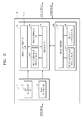
- FIG. 2 is a detailed block diagram illustrating the processor 130, according to an embodiment.
- the processor 130 includes a pre-processing unit 131, a first image processor 141, and a second image processor 146. It may be understood by one of ordinary skill in the art related to the present embodiment that general-use elements other than the processor modules shown in FIG. 2 may be further included.
- the photographing apparatus 100 divides the input image provided to the processor 130 into at least two input images; instructs at least two image processors to perform imaging processes; and uses one or more of the image processors to combine the divided images. That is, in order to process a high definition image which may be difficult to process with just one image processor, the photographing apparatus 100 uses at least two image processors to process a photographed image into a high definition image.
- the embodiment will be described with respect to a case of using two image processors to process a high definition image, in which the input image provided to the processor 130 is divided into first and second input images.
- the photographing apparatus 100 divides the input image provided to the processor 130 into the first and second input images, and independently process the first and second input images in the first image processor 141 and the second image processor 146, respectively. Then, in order to process the UHD image from the independently processed images, the photographing apparatus 100 combines and stores the independently processed images.
- the photographing apparatus 100 performs a high definition imaging process for the photographed images to provide an UHD image, and store the stored image in the image storage unit 170, a separate imaging process is performed and the display image is displayed on the display unit 150, in order to reduce the delay until the display image is displayed on the display unit 150 thereof.
- FIG. 2 a specific description referring to FIG. 2 will be given below.
- analog signal which is transferred from the imaging device 115 to an analog signal processing unit (not shown)
- processes such as noise reduction, gain control, wave shaping, and analog-to-digital conversion are performed and then the input image is provided to the processor 130.
- the input image provided to the processor 130 is transferred to the pre-processing unit 131.
- the pre-processing unit 131 processes the input image into an image which may be processed by the first image processor 141 and the second image processor 146.
- the pre-processing unit 131 includes a size adjustment unit 133 and an image division unit 135. Because the photographing apparatus 100 may include at least two image processors for processing the input images, the processing performance of the pre-processing unit 131 may be proportional to the number of image processors included in the photographing apparatus 100, rather than the processing performance of any one of the image processors. For example, when there are two image processors in total, such as the first image processor 141 and the second image processor 146, the processing performance of the pre-processing unit 131 may be twice the processing performance of the first image processor 141 or the second image processor 146.
- the size adjustment unit 133 adjusts the size of the input image and transfers the input image to the first image processor 141. Specifically, the size adjustment unit 133 adjusts the input image provided to the processor 130 into an appropriate size to be displayed on the display unit 150, in order for the first image processor 141 to smoothly generate the display image for the display unit 150.
- the size adjustment unit 133 may take the resolution supported by the display unit 150, or the processing performance of a display image process unit 142 of the first image processor 141 into account, and adjusts the size of the input image.
- the image division unit 135 divides the input image into the first and second input images and outputs the divided images to the first image processor 141.
- the image division unit 135 may perform a time division, which divides the input image by frames; or a space division, which divides the input image by screen areas on the display unit 150. For example, when performing the time division, the image division unit 135 may divide the frames of the input image into odd numbered and even numbered frames; set odd numbered frames as the first input image, and the even numbered frames as the second input image; and then, transfer the divided images to the first image processor 141.
- the image division unit 135 may divide the input image by the screen areas on the display unit 150, and set the frames of the input image corresponding to a first area as the first input image, and the frames thereof corresponding to a second area as the second input image; and transfer the divided images to the first image processor 141.
- the image division unit 135 may transfer the first and second input images to the second image processor 146, instead of the first image processor 141.
- the embodiment will be described on the premise of the image division unit 135 transferring the first and second input images to the first image processor 141.
- the image division unit 135 divides the input image according to the definition of the stored image set by the user of the photographing apparatus 100. For example, if the user thereof sets the resolution of the stored image as UHD, the image division unit 135 may perform the time division or space division on the input image. If the user thereof sets the resolution of the stored image as HD, the image division unit 135 may not divide the input image but directly transfer the input image to the first image processor 141.
- the first image processor 141 may include the display image process unit 142, a first stored image processing unit 144, and a first compression unit 145.
- the first image processor 141 generates a display image from the input image.
- the first image is divided into the first input image and the second input image.
- the first image processor 141 generates a first stored image from the first input image.
- the display image process unit 142 generates display images from input images.
- the generated display images have the same frame rate and viewing angle as those of the input images.
- a size-adjusted input image provided by the size adjustment unit 133 is not stored in a first memory 143 in the first image processor 141 in one example, but is directly input to the display image process unit 142.
- the display image process unit 142 generates the display image from the size-adjusted input image.
- the generated display image has the same frame rate and viewing angle as those of the input image.
- the first input image and the second input image, which are output from the image division unit 135, are stored in the first memory 143 in the first image processor 141.
- the first stored image processing unit 144 generates the first stored image from the first input image, which is a portion of the divided input image.
- the first compression unit 145 compresses the generated first stored image into an appropriate format.
- the second input image stored in the first memory 143 is transferred to the second image processor 146 by an image transfer interface such as a mobile industry processor interface (MIPI). That is, when the first input image stored in the first memory 143 is processed by the first stored image processing unit 144, the second input image stored in the first memory 143 is transferred to the second image processor 146, and stored in a second memory 147 in the second image processor 146. Contrary to FIG.
- MIPI mobile industry processor interface
- the first and second input images divided by the image division unit 135 are output to the second image processor 146 instead of the first image processor 141, and then, when the second input image stored in the second memory 147 is processed by a second stored image processing unit 148, the first input image stored in the second memory 147 is transferred to the first image processor 141, and stored in the first memory 143 in the first image processor 141.
- the first image processor 141 and the second image processor 146 have the first and second input images, respectively.
- a delay may occur during the division process using the image transfer interface to transfer the second input image to the second image processor 146 or the first input image to the first input image processor 141.
- the display image process unit 142 is separately included in the first image processor 141 so as to not be influenced by the delay that may occur during the division process, to thus reduce an image display delay that may occur until the actual image input in the photographing apparatus 100 (e.g., the display image) is displayed on the display unit 150 of the photographing apparatus 100.
- the display image process unit 142 may also be separately included to display the delay-reduced image on the display unit 150, to thereby allow the user of the photographing apparatus 100 to identify live view images and to simultaneously store high definition images, and thus improve the processing performance of the photographing apparatus 100 and increase user-convenience.
- the second image processor 146 includes the second memory 147, the second stored image processing unit 148, and a second compression unit 149.
- the second image processor 146 generates a second stored image from the second input image, which is an image other than the first input image of the divided input image.
- the first and second input images output from the image division unit 135, are stored in the first memory 143 in the first image processor 141. From the stored images, the second input image is transferred to the second image processor 146 by the image transfer interface, and stored in the second memory 147 in the second image processor 146.
- the second stored image processing unit 148 receives the second input image from the second memory 147, and generates the second stored image which has the same frame rate and resolution as those of the first stored image.
- the second compression unit 149 compresses the generated second stored image into an appropriate format.
- the first and second stored images having undergone the imaging process and the compression process by the first image processor 141 and the second image processor 146, respectively, are combined in any one of the first image processor 141 or the second image processor 146.
- the first stored image, which has undergone imaging process and was compressed by the first image processer 141 is transferred to the second image processor 146; or, the second stored image, which has been image processed and compressed by the second image processor 146, is transferred to the first image processor 141.
- a delay may occur during the combination process using the image transfer interface, in which the combination process includes transferring the first input image to the second image processor 146 or the second input image to the first input image processor 141.
- the display image process unit 142 is separately included in the first image processor 141 so as to not be influenced by the delay that may occur during the division process, to thus reduce an image display delay that may occur until the actual image input in the photographing apparatus 100 is displayed on the display unit of the photographing apparatus 100.
- the display image process unit 142 may also be included separately to display the delay-reduced image on the display unit 150, to thereby allow the user of the photographing apparatus 100 to identify live view images and to simultaneously store high definition images, and thus improve the processing performance of the photographing apparatus 100 and increase user-convenience.
- the stored image which is a combination of the first and second stored images, may have a UHD-level resolution.
- FIG. 3 is a flowchart illustrating a method of controlling an electronic apparatus (e.g., the photographing apparatus 100).
- an electronic apparatus e.g., the photographing apparatus 100
- the description regarding the photographing apparatus 100 may be applied to other electronic apparatuses according to the embodiments.
- an input image is generated by a photoelectric conversion of incident light.
- the display image is generated from the input image.
- the display image maintains the frame rate and the viewing angle of the input image.
- the process of generating the display image from the input image is independently performed from the process of generating the first and second stored images from the first and second input images, respectively, in which the first and second input images are divided from the input image.
- separately generating a display image that is different from the stored image provides a reduction in the effect of delay that may occur during the process of generating a high-definition stored image.
- operation 320 which is a process of generating the display image, will be described in more detail by referring to FIG. 4 .
- FIG. 4 is a detail flowchart illustrating a process of generating the display image.
- the size of the input image is adjusted. Specifically, the size of the input image is adjusted to an appropriate size for displaying on the display unit 150, so that the display image to be displayed on the display unit 150 is smoothly generated.
- the size of the input image may be adjusted.
- the display image is generated from the size-adjusted input image.
- the generated display image has the same frame rate and viewing angle as those of the size-adjusted input image.
- the display image is displayed, which is an image generated by a predetermined image signal process to be displayed on the display unit 150.
- the first and second input images are divided from the input image.
- the first and second stored images are generated from the first and second input images, respectively.
- the first and second stored images are independently generated from separate image processors (141 and 146)
- the first and second stored images have an identical frame rate and resolution.
- the process of generating the first and second stored images from the first and second input images, respectively, in which the first and second input images are divided from the input image is independently performed from the process of generating the display image from the input image.
- the process of respectively generating the first and second stored images from the first and second input images is performed independently from the process of generating the display image from the input image to provide a reduction in the effect of delay that may occur during the process of generating a high-definition stored image.
- operation 340 for generating the first and second stored images is described in more detail, referring to FIG. 5 .
- FIG. 5 is a detail flowchart illustrating a process of generating first and second stored images.
- the input image is divided into the first and second input images.
- the input image may be divided by a time division, which divides the input image by frames; or a space division, which divides the input image by screen areas.
- the frames of the input image are divided into odd numbered and even numbered frames; and then, the odd numbered frames may be set as the first input image, and the even numbered frames may be set as the second input image.
- the input image is divided by the screen areas displayed on the display unit 150, and the frames of the input image corresponding to the first area are set as the first input image, and the frames thereof corresponding to the second area are set as the second input image.
- the division of the input images is performed based on the resolution of the stored image set by the user of the photographing apparatus 100.
- the first and second stored images are generated, respectively. Specifically, from the first input image, which is a portion of the divided input image, the first stored image is generated, and compressed into an appropriate format. Also, from the second input image, which is an image other than the first stored image of the divided input images, the second stored image with the same frame rate and resolution as those of the first stored image is generated, and compressed into an appropriate format.
- a combined image of the first and second stored images is stored as the stored image.
- the first and second stored images on which at least two image processors independently and respectively performed imaging process and compression, are combined as a single image and stored as the stored image.
- the first stored image which has undergone the imaging process and compression in one of the processors, may be transferred to the other image processor, or, in opposite, the second stored image, which has undergone the imaging process and compression, may be transferred to the image processor where the first stored image is stored. Therefore, by combining the first and second stored images, which are stored in the memory of a single image processor, an image with a higher definition, that is, an UHD-level stored image may be generated and stored in the image storage unit 170.
- the apparatus described herein may comprise a processor, a memory for storing program data to be executed by the processor, a permanent storage such as a disk drive, a communications port for handling communications with external devices, and user interface devices, including a display, touch panel, keys, buttons, etc.
- these software modules may be stored as program instructions or computer readable code executable by the processor on a non-transitory computer-readable media such as magnetic storage media (e.g., magnetic tapes, hard disks, floppy disks), optical recording media (e.g., CD-ROMs, Digital Versatile Discs (DVDs), etc.), and solid state memory (e.g., random-access memory (RAM), read-only memory (ROM), static random-access memory (SRAM), electrically erasable programmable read-only memory (EEPROM), flash memory, thumb drives, etc.).
- the computer readable recording media may also be distributed over network coupled computer systems so that the computer readable code is stored and executed in a distributed fashion. This computer readable recording media may be read by the computer, stored in the memory, and executed by the processor.
- the user of the photographing apparatus may identify the live view image, and store a high definition image.
- the processing performance of the photographing apparatus may be improved and the user-convenience may be increased.
- the invention may be described in terms of functional block components and various processing steps. Such functional blocks may be realized by any number of hardware and/or software components configured to perform the specified functions.
- the invention may employ various integrated circuit components, e.g., memory elements, processing elements, logic elements, look-up tables, and the like, which may carry out a variety of functions under the control of one or more microprocessors or other control devices.
- the elements of the invention are implemented using software programming or software elements
- the invention may be implemented with any programming or scripting language such as C, C++, JAVA®, assembler, or the like, with the various algorithms being implemented with any combination of data structures, objects, processes, routines or other programming elements.
- Functional aspects may be implemented in algorithms that execute on one or more processors.
- the invention may employ any number of conventional techniques for electronics configuration, signal processing and/or control, data processing and the like.
Landscapes
- Engineering & Computer Science (AREA)
- Multimedia (AREA)
- Signal Processing (AREA)
- Computing Systems (AREA)
- Theoretical Computer Science (AREA)
- Studio Devices (AREA)
- Image Processing (AREA)
- Apparatus For Radiation Diagnosis (AREA)
Applications Claiming Priority (1)
| Application Number | Priority Date | Filing Date | Title |
|---|---|---|---|
| KR1020130022457A KR102014444B1 (ko) | 2013-02-28 | 2013-02-28 | 촬영 장치 및 촬영 장치를 제어하는 방법, 그리고 컴퓨터 판독가능 기록매체 |
Publications (3)
| Publication Number | Publication Date |
|---|---|
| EP2773101A2 true EP2773101A2 (de) | 2014-09-03 |
| EP2773101A3 EP2773101A3 (de) | 2015-09-09 |
| EP2773101B1 EP2773101B1 (de) | 2020-04-01 |
Family
ID=50193220
Family Applications (1)
| Application Number | Title | Priority Date | Filing Date |
|---|---|---|---|
| EP14156104.3A Not-in-force EP2773101B1 (de) | 2013-02-28 | 2014-02-21 | Elektronische Vorrichtung, Verfahren zu ihrer Steuerung und computerlesbares Aufzeichnungsmedium |
Country Status (3)
| Country | Link |
|---|---|
| US (1) | US9277119B2 (de) |
| EP (1) | EP2773101B1 (de) |
| KR (1) | KR102014444B1 (de) |
Families Citing this family (1)
| Publication number | Priority date | Publication date | Assignee | Title |
|---|---|---|---|---|
| US11429226B2 (en) * | 2018-08-27 | 2022-08-30 | Sigmasense, Llc. | Analog-digital drive sense circuit |
Family Cites Families (17)
| Publication number | Priority date | Publication date | Assignee | Title |
|---|---|---|---|---|
| KR100253002B1 (ko) * | 1997-11-28 | 2000-04-15 | 구자홍 | 디티브이의 디스플레이용 영상 처리장치 및 그 방법 |
| JPH11239329A (ja) | 1998-02-23 | 1999-08-31 | Sony Corp | 画像伝送装置およびそれを使用した画像伝送システム |
| US7133407B2 (en) * | 2000-01-25 | 2006-11-07 | Fujitsu Limited | Data communications system |
| US7027665B1 (en) * | 2000-09-29 | 2006-04-11 | Microsoft Corporation | Method and apparatus for reducing image acquisition time in a digital imaging device |
| JP2002247593A (ja) * | 2001-02-16 | 2002-08-30 | Olympus Optical Co Ltd | 画像処理装置 |
| JP2003037816A (ja) | 2001-07-23 | 2003-02-07 | Sharp Corp | 動画像符号化方法 |
| JP3956010B2 (ja) | 2002-03-26 | 2007-08-08 | 富士通株式会社 | 映像伝送システム及び映像伝送制御方法 |
| JP2004289631A (ja) * | 2003-03-24 | 2004-10-14 | Fuji Photo Film Co Ltd | デジタルカメラ |
| KR100834669B1 (ko) * | 2006-10-20 | 2008-06-02 | 삼성전자주식회사 | 썸네일 이미지 생성을 위한 웨이블릿 변환 기반 이미지부호화기, 복호화기 및 그 방법 |
| KR20100095740A (ko) * | 2009-02-23 | 2010-09-01 | 삼성전자주식회사 | 디스플레이장치 및 그 제어 방법 |
| JP5568884B2 (ja) * | 2009-04-02 | 2014-08-13 | セイコーエプソン株式会社 | 映像処理装置、映像処理方法 |
| KR20100132429A (ko) | 2009-06-09 | 2010-12-17 | 삼성전자주식회사 | 대용량의 영상을 효율적으로 전송하는 영상 부호화 장치 및 영상 복호화 장치 |
| JP5325745B2 (ja) | 2009-11-02 | 2013-10-23 | 株式会社ソニー・コンピュータエンタテインメント | 動画像処理プログラム、装置および方法、動画像処理装置を搭載した撮像装置 |
| KR101085554B1 (ko) | 2009-11-19 | 2011-11-24 | 에이스텔 주식회사 | 초고화질 영상을 위한 실시간 입출력 모듈 시스템 |
| JP2011109611A (ja) | 2009-11-20 | 2011-06-02 | Toshiba Corp | ヘッド分離式カメラ装置 |
| JP5640370B2 (ja) * | 2009-12-18 | 2014-12-17 | ソニー株式会社 | 画像処理装置,画像処理方法及び撮像装置 |
| JP2012248984A (ja) | 2011-05-26 | 2012-12-13 | Sony Corp | 信号送信装置、信号送信方法、信号受信装置、信号受信方法及び信号伝送システム |
-
2013
- 2013-02-28 KR KR1020130022457A patent/KR102014444B1/ko not_active Expired - Fee Related
-
2014
- 2014-02-21 EP EP14156104.3A patent/EP2773101B1/de not_active Not-in-force
- 2014-02-26 US US14/190,551 patent/US9277119B2/en not_active Expired - Fee Related
Non-Patent Citations (1)
| Title |
|---|
| None |
Also Published As
| Publication number | Publication date |
|---|---|
| KR20140108034A (ko) | 2014-09-05 |
| EP2773101B1 (de) | 2020-04-01 |
| KR102014444B1 (ko) | 2019-08-26 |
| EP2773101A3 (de) | 2015-09-09 |
| US20140240545A1 (en) | 2014-08-28 |
| US9277119B2 (en) | 2016-03-01 |
Similar Documents
| Publication | Publication Date | Title |
|---|---|---|
| EP2525565B1 (de) | Digitales Fotografiergerät und Verfahren zur Steuerung davon zur Erhöhung der Serienaufnahmegeschwindigkeit zur Erfassung von Panoramafotos | |
| CN102892008B (zh) | 双图像捕获处理 | |
| CN106576143B (zh) | 图像拍摄装置和图像拍摄方法 | |
| US8633998B2 (en) | Imaging apparatus and display apparatus | |
| US20130176458A1 (en) | Flexible Burst Image Capture System | |
| US9578260B2 (en) | Digital photographing apparatus and method of controlling the digital photographing apparatus | |
| US8526685B2 (en) | Method and apparatus for selectively supporting raw format in digital image processor | |
| CN102088559B (zh) | 数字拍摄设备及其控制方法 | |
| US20110234881A1 (en) | Display apparatus | |
| US8681245B2 (en) | Digital photographing apparatus, and method for providing bokeh effects | |
| US9635269B2 (en) | Electronic apparatus and method | |
| US20130155117A1 (en) | Display apparatus and method and computer-readable storage medium | |
| US20130162853A1 (en) | Digital photographing apparatus and method of controlling the same | |
| US9077894B2 (en) | Method and apparatus for capturing still image during photographing or reproduction of moving image | |
| US9723194B2 (en) | Photographing apparatus providing image transmission based on communication status, method of controlling the same, and non-transitory computer-readable storage medium for executing the method | |
| CN103024262A (zh) | 显示设备和方法 | |
| EP2890116A1 (de) | Verfahren zur Anzeige eines Fotografiermodus durch Verwendung von Objektiveigenschaften, computerlesbares Speichermedium zur Aufzeichnung des Verfahrens und elektronische Vorrichtung | |
| KR20150116350A (ko) | 촬영 장치 및 이의 제어 방법 | |
| US20130321664A1 (en) | Photographing apparatus, method of controlling the same, and computer-readable recording medium | |
| JP7110408B2 (ja) | 画像処理装置、撮影装置、画像処理方法及び画像処理プログラム | |
| EP2773101B1 (de) | Elektronische Vorrichtung, Verfahren zu ihrer Steuerung und computerlesbares Aufzeichnungsmedium | |
| KR20150093431A (ko) | 복수의 렌즈를 이용하는 촬영 장치 및 방법 |
Legal Events
| Date | Code | Title | Description |
|---|---|---|---|
| PUAI | Public reference made under article 153(3) epc to a published international application that has entered the european phase |
Free format text: ORIGINAL CODE: 0009012 |
|
| 17P | Request for examination filed |
Effective date: 20140221 |
|
| AK | Designated contracting states |
Kind code of ref document: A2 Designated state(s): AL AT BE BG CH CY CZ DE DK EE ES FI FR GB GR HR HU IE IS IT LI LT LU LV MC MK MT NL NO PL PT RO RS SE SI SK SM TR |
|
| AX | Request for extension of the european patent |
Extension state: BA ME |
|
| PUAL | Search report despatched |
Free format text: ORIGINAL CODE: 0009013 |
|
| AK | Designated contracting states |
Kind code of ref document: A3 Designated state(s): AL AT BE BG CH CY CZ DE DK EE ES FI FR GB GR HR HU IE IS IT LI LT LU LV MC MK MT NL NO PL PT RO RS SE SI SK SM TR |
|
| AX | Request for extension of the european patent |
Extension state: BA ME |
|
| RIC1 | Information provided on ipc code assigned before grant |
Ipc: H04N 5/232 20060101AFI20150804BHEP Ipc: H04N 5/272 20060101ALI20150804BHEP |
|
| 17Q | First examination report despatched |
Effective date: 20150820 |
|
| RBV | Designated contracting states (corrected) |
Designated state(s): AL AT BE BG CH CY CZ DE DK EE ES FI FR GB GR HR HU IE IS IT LI LT LU LV MC MK MT NL NO PL PT RO RS SE SI SK SM TR |
|
| STAA | Information on the status of an ep patent application or granted ep patent |
Free format text: STATUS: EXAMINATION IS IN PROGRESS |
|
| GRAP | Despatch of communication of intention to grant a patent |
Free format text: ORIGINAL CODE: EPIDOSNIGR1 |
|
| STAA | Information on the status of an ep patent application or granted ep patent |
Free format text: STATUS: GRANT OF PATENT IS INTENDED |
|
| INTG | Intention to grant announced |
Effective date: 20191114 |
|
| GRAS | Grant fee paid |
Free format text: ORIGINAL CODE: EPIDOSNIGR3 |
|
| GRAA | (expected) grant |
Free format text: ORIGINAL CODE: 0009210 |
|
| STAA | Information on the status of an ep patent application or granted ep patent |
Free format text: STATUS: THE PATENT HAS BEEN GRANTED |
|
| AK | Designated contracting states |
Kind code of ref document: B1 Designated state(s): AL AT BE BG CH CY CZ DE DK EE ES FI FR GB GR HR HU IE IS IT LI LT LU LV MC MK MT NL NO PL PT RO RS SE SI SK SM TR |
|
| REG | Reference to a national code |
Ref country code: GB Ref legal event code: FG4D |
|
| REG | Reference to a national code |
Ref country code: AT Ref legal event code: REF Ref document number: 1252873 Country of ref document: AT Kind code of ref document: T Effective date: 20200415 Ref country code: CH Ref legal event code: EP |
|
| REG | Reference to a national code |
Ref country code: DE Ref legal event code: R096 Ref document number: 602014063049 Country of ref document: DE |
|
| REG | Reference to a national code |
Ref country code: IE Ref legal event code: FG4D |
|
| PG25 | Lapsed in a contracting state [announced via postgrant information from national office to epo] |
Ref country code: BG Free format text: LAPSE BECAUSE OF FAILURE TO SUBMIT A TRANSLATION OF THE DESCRIPTION OR TO PAY THE FEE WITHIN THE PRESCRIBED TIME-LIMIT Effective date: 20200701 |
|
| REG | Reference to a national code |
Ref country code: NL Ref legal event code: MP Effective date: 20200401 |
|
| REG | Reference to a national code |
Ref country code: LT Ref legal event code: MG4D |
|
| PG25 | Lapsed in a contracting state [announced via postgrant information from national office to epo] |
Ref country code: SE Free format text: LAPSE BECAUSE OF FAILURE TO SUBMIT A TRANSLATION OF THE DESCRIPTION OR TO PAY THE FEE WITHIN THE PRESCRIBED TIME-LIMIT Effective date: 20200401 Ref country code: IS Free format text: LAPSE BECAUSE OF FAILURE TO SUBMIT A TRANSLATION OF THE DESCRIPTION OR TO PAY THE FEE WITHIN THE PRESCRIBED TIME-LIMIT Effective date: 20200801 Ref country code: FI Free format text: LAPSE BECAUSE OF FAILURE TO SUBMIT A TRANSLATION OF THE DESCRIPTION OR TO PAY THE FEE WITHIN THE PRESCRIBED TIME-LIMIT Effective date: 20200401 Ref country code: NO Free format text: LAPSE BECAUSE OF FAILURE TO SUBMIT A TRANSLATION OF THE DESCRIPTION OR TO PAY THE FEE WITHIN THE PRESCRIBED TIME-LIMIT Effective date: 20200701 Ref country code: NL Free format text: LAPSE BECAUSE OF FAILURE TO SUBMIT A TRANSLATION OF THE DESCRIPTION OR TO PAY THE FEE WITHIN THE PRESCRIBED TIME-LIMIT Effective date: 20200401 Ref country code: CZ Free format text: LAPSE BECAUSE OF FAILURE TO SUBMIT A TRANSLATION OF THE DESCRIPTION OR TO PAY THE FEE WITHIN THE PRESCRIBED TIME-LIMIT Effective date: 20200401 Ref country code: LT Free format text: LAPSE BECAUSE OF FAILURE TO SUBMIT A TRANSLATION OF THE DESCRIPTION OR TO PAY THE FEE WITHIN THE PRESCRIBED TIME-LIMIT Effective date: 20200401 Ref country code: PT Free format text: LAPSE BECAUSE OF FAILURE TO SUBMIT A TRANSLATION OF THE DESCRIPTION OR TO PAY THE FEE WITHIN THE PRESCRIBED TIME-LIMIT Effective date: 20200817 Ref country code: GR Free format text: LAPSE BECAUSE OF FAILURE TO SUBMIT A TRANSLATION OF THE DESCRIPTION OR TO PAY THE FEE WITHIN THE PRESCRIBED TIME-LIMIT Effective date: 20200702 |
|
| REG | Reference to a national code |
Ref country code: AT Ref legal event code: MK05 Ref document number: 1252873 Country of ref document: AT Kind code of ref document: T Effective date: 20200401 |
|
| PG25 | Lapsed in a contracting state [announced via postgrant information from national office to epo] |
Ref country code: LV Free format text: LAPSE BECAUSE OF FAILURE TO SUBMIT A TRANSLATION OF THE DESCRIPTION OR TO PAY THE FEE WITHIN THE PRESCRIBED TIME-LIMIT Effective date: 20200401 Ref country code: HR Free format text: LAPSE BECAUSE OF FAILURE TO SUBMIT A TRANSLATION OF THE DESCRIPTION OR TO PAY THE FEE WITHIN THE PRESCRIBED TIME-LIMIT Effective date: 20200401 Ref country code: RS Free format text: LAPSE BECAUSE OF FAILURE TO SUBMIT A TRANSLATION OF THE DESCRIPTION OR TO PAY THE FEE WITHIN THE PRESCRIBED TIME-LIMIT Effective date: 20200401 |
|
| PG25 | Lapsed in a contracting state [announced via postgrant information from national office to epo] |
Ref country code: AL Free format text: LAPSE BECAUSE OF FAILURE TO SUBMIT A TRANSLATION OF THE DESCRIPTION OR TO PAY THE FEE WITHIN THE PRESCRIBED TIME-LIMIT Effective date: 20200401 |
|
| REG | Reference to a national code |
Ref country code: DE Ref legal event code: R097 Ref document number: 602014063049 Country of ref document: DE |
|
| PG25 | Lapsed in a contracting state [announced via postgrant information from national office to epo] |
Ref country code: SM Free format text: LAPSE BECAUSE OF FAILURE TO SUBMIT A TRANSLATION OF THE DESCRIPTION OR TO PAY THE FEE WITHIN THE PRESCRIBED TIME-LIMIT Effective date: 20200401 Ref country code: RO Free format text: LAPSE BECAUSE OF FAILURE TO SUBMIT A TRANSLATION OF THE DESCRIPTION OR TO PAY THE FEE WITHIN THE PRESCRIBED TIME-LIMIT Effective date: 20200401 Ref country code: ES Free format text: LAPSE BECAUSE OF FAILURE TO SUBMIT A TRANSLATION OF THE DESCRIPTION OR TO PAY THE FEE WITHIN THE PRESCRIBED TIME-LIMIT Effective date: 20200401 Ref country code: EE Free format text: LAPSE BECAUSE OF FAILURE TO SUBMIT A TRANSLATION OF THE DESCRIPTION OR TO PAY THE FEE WITHIN THE PRESCRIBED TIME-LIMIT Effective date: 20200401 Ref country code: AT Free format text: LAPSE BECAUSE OF FAILURE TO SUBMIT A TRANSLATION OF THE DESCRIPTION OR TO PAY THE FEE WITHIN THE PRESCRIBED TIME-LIMIT Effective date: 20200401 Ref country code: DK Free format text: LAPSE BECAUSE OF FAILURE TO SUBMIT A TRANSLATION OF THE DESCRIPTION OR TO PAY THE FEE WITHIN THE PRESCRIBED TIME-LIMIT Effective date: 20200401 |
|
| PLBE | No opposition filed within time limit |
Free format text: ORIGINAL CODE: 0009261 |
|
| STAA | Information on the status of an ep patent application or granted ep patent |
Free format text: STATUS: NO OPPOSITION FILED WITHIN TIME LIMIT |
|
| PG25 | Lapsed in a contracting state [announced via postgrant information from national office to epo] |
Ref country code: PL Free format text: LAPSE BECAUSE OF FAILURE TO SUBMIT A TRANSLATION OF THE DESCRIPTION OR TO PAY THE FEE WITHIN THE PRESCRIBED TIME-LIMIT Effective date: 20200401 Ref country code: SK Free format text: LAPSE BECAUSE OF FAILURE TO SUBMIT A TRANSLATION OF THE DESCRIPTION OR TO PAY THE FEE WITHIN THE PRESCRIBED TIME-LIMIT Effective date: 20200401 |
|
| 26N | No opposition filed |
Effective date: 20210112 |
|
| PG25 | Lapsed in a contracting state [announced via postgrant information from national office to epo] |
Ref country code: SI Free format text: LAPSE BECAUSE OF FAILURE TO SUBMIT A TRANSLATION OF THE DESCRIPTION OR TO PAY THE FEE WITHIN THE PRESCRIBED TIME-LIMIT Effective date: 20200401 |
|
| PG25 | Lapsed in a contracting state [announced via postgrant information from national office to epo] |
Ref country code: MC Free format text: LAPSE BECAUSE OF FAILURE TO SUBMIT A TRANSLATION OF THE DESCRIPTION OR TO PAY THE FEE WITHIN THE PRESCRIBED TIME-LIMIT Effective date: 20200401 |
|
| REG | Reference to a national code |
Ref country code: BE Ref legal event code: MM Effective date: 20210228 |
|
| PG25 | Lapsed in a contracting state [announced via postgrant information from national office to epo] |
Ref country code: LI Free format text: LAPSE BECAUSE OF NON-PAYMENT OF DUE FEES Effective date: 20210228 Ref country code: LU Free format text: LAPSE BECAUSE OF NON-PAYMENT OF DUE FEES Effective date: 20210221 Ref country code: CH Free format text: LAPSE BECAUSE OF NON-PAYMENT OF DUE FEES Effective date: 20210228 |
|
| PG25 | Lapsed in a contracting state [announced via postgrant information from national office to epo] |
Ref country code: FR Free format text: LAPSE BECAUSE OF NON-PAYMENT OF DUE FEES Effective date: 20210228 Ref country code: IE Free format text: LAPSE BECAUSE OF NON-PAYMENT OF DUE FEES Effective date: 20210221 |
|
| PGFP | Annual fee paid to national office [announced via postgrant information from national office to epo] |
Ref country code: GB Payment date: 20220121 Year of fee payment: 9 Ref country code: DE Payment date: 20220120 Year of fee payment: 9 |
|
| PGFP | Annual fee paid to national office [announced via postgrant information from national office to epo] |
Ref country code: IT Payment date: 20220120 Year of fee payment: 9 |
|
| PG25 | Lapsed in a contracting state [announced via postgrant information from national office to epo] |
Ref country code: BE Free format text: LAPSE BECAUSE OF NON-PAYMENT OF DUE FEES Effective date: 20210228 |
|
| REG | Reference to a national code |
Ref country code: DE Ref legal event code: R079 Ref document number: 602014063049 Country of ref document: DE Free format text: PREVIOUS MAIN CLASS: H04N0005232000 Ipc: H04N0023600000 |
|
| PG25 | Lapsed in a contracting state [announced via postgrant information from national office to epo] |
Ref country code: HU Free format text: LAPSE BECAUSE OF FAILURE TO SUBMIT A TRANSLATION OF THE DESCRIPTION OR TO PAY THE FEE WITHIN THE PRESCRIBED TIME-LIMIT; INVALID AB INITIO Effective date: 20140221 |
|
| PG25 | Lapsed in a contracting state [announced via postgrant information from national office to epo] |
Ref country code: CY Free format text: LAPSE BECAUSE OF FAILURE TO SUBMIT A TRANSLATION OF THE DESCRIPTION OR TO PAY THE FEE WITHIN THE PRESCRIBED TIME-LIMIT Effective date: 20200401 |
|
| REG | Reference to a national code |
Ref country code: DE Ref legal event code: R119 Ref document number: 602014063049 Country of ref document: DE |
|
| GBPC | Gb: european patent ceased through non-payment of renewal fee |
Effective date: 20230221 |
|
| PG25 | Lapsed in a contracting state [announced via postgrant information from national office to epo] |
Ref country code: GB Free format text: LAPSE BECAUSE OF NON-PAYMENT OF DUE FEES Effective date: 20230221 |
|
| PG25 | Lapsed in a contracting state [announced via postgrant information from national office to epo] |
Ref country code: IT Free format text: LAPSE BECAUSE OF NON-PAYMENT OF DUE FEES Effective date: 20230221 Ref country code: GB Free format text: LAPSE BECAUSE OF NON-PAYMENT OF DUE FEES Effective date: 20230221 Ref country code: DE Free format text: LAPSE BECAUSE OF NON-PAYMENT OF DUE FEES Effective date: 20230901 |
|
| PG25 | Lapsed in a contracting state [announced via postgrant information from national office to epo] |
Ref country code: MK Free format text: LAPSE BECAUSE OF FAILURE TO SUBMIT A TRANSLATION OF THE DESCRIPTION OR TO PAY THE FEE WITHIN THE PRESCRIBED TIME-LIMIT Effective date: 20200401 |
|
| PG25 | Lapsed in a contracting state [announced via postgrant information from national office to epo] |
Ref country code: TR Free format text: LAPSE BECAUSE OF FAILURE TO SUBMIT A TRANSLATION OF THE DESCRIPTION OR TO PAY THE FEE WITHIN THE PRESCRIBED TIME-LIMIT Effective date: 20200401 |
|
| PG25 | Lapsed in a contracting state [announced via postgrant information from national office to epo] |
Ref country code: MT Free format text: LAPSE BECAUSE OF FAILURE TO SUBMIT A TRANSLATION OF THE DESCRIPTION OR TO PAY THE FEE WITHIN THE PRESCRIBED TIME-LIMIT Effective date: 20200401 |