EP2770724A2 - Vorrichtung und Verfahren zur Positionierung eines Bildbereichs unter Verwendung der Bildsensorstelle - Google Patents
Vorrichtung und Verfahren zur Positionierung eines Bildbereichs unter Verwendung der Bildsensorstelle Download PDFInfo
- Publication number
- EP2770724A2 EP2770724A2 EP14156084.7A EP14156084A EP2770724A2 EP 2770724 A2 EP2770724 A2 EP 2770724A2 EP 14156084 A EP14156084 A EP 14156084A EP 2770724 A2 EP2770724 A2 EP 2770724A2
- Authority
- EP
- European Patent Office
- Prior art keywords
- image
- display
- image sensor
- preview
- displaying
- Prior art date
- Legal status (The legal status is an assumption and is not a legal conclusion. Google has not performed a legal analysis and makes no representation as to the accuracy of the status listed.)
- Granted
Links
Images


Classifications
-
- H—ELECTRICITY
- H04—ELECTRIC COMMUNICATION TECHNIQUE
- H04N—PICTORIAL COMMUNICATION, e.g. TELEVISION
- H04N23/00—Cameras or camera modules comprising electronic image sensors; Control thereof
- H04N23/60—Control of cameras or camera modules
- H04N23/63—Control of cameras or camera modules by using electronic viewfinders
-
- H—ELECTRICITY
- H04—ELECTRIC COMMUNICATION TECHNIQUE
- H04N—PICTORIAL COMMUNICATION, e.g. TELEVISION
- H04N5/00—Details of television systems
- H04N5/222—Studio circuitry; Studio devices; Studio equipment
- H04N5/262—Studio circuits, e.g. for mixing, switching-over, change of character of image, other special effects ; Cameras specially adapted for the electronic generation of special effects
- H04N5/272—Means for inserting a foreground image in a background image, i.e. inlay, outlay
-
- H—ELECTRICITY
- H04—ELECTRIC COMMUNICATION TECHNIQUE
- H04N—PICTORIAL COMMUNICATION, e.g. TELEVISION
- H04N23/00—Cameras or camera modules comprising electronic image sensors; Control thereof
- H04N23/45—Cameras or camera modules comprising electronic image sensors; Control thereof for generating image signals from two or more image sensors being of different type or operating in different modes, e.g. with a CMOS sensor for moving images in combination with a charge-coupled device [CCD] for still images
-
- H—ELECTRICITY
- H04—ELECTRIC COMMUNICATION TECHNIQUE
- H04N—PICTORIAL COMMUNICATION, e.g. TELEVISION
- H04N23/00—Cameras or camera modules comprising electronic image sensors; Control thereof
- H04N23/60—Control of cameras or camera modules
- H04N23/62—Control of parameters via user interfaces
-
- H—ELECTRICITY
- H04—ELECTRIC COMMUNICATION TECHNIQUE
- H04N—PICTORIAL COMMUNICATION, e.g. TELEVISION
- H04N23/00—Cameras or camera modules comprising electronic image sensors; Control thereof
- H04N23/60—Control of cameras or camera modules
- H04N23/64—Computer-aided capture of images, e.g. transfer from script file into camera, check of taken image quality, advice or proposal for image composition or decision on when to take image
Definitions
- the present disclosure relates to an apparatus and a method for photographing a still or moving image by using a portable electronic device having a camera function. More particularly, the present disclosure relates to an apparatus and a method for photographing an image by using a plurality of image sensors in a portable electronic device.
- a method for photographing with a camera device includes displaying image data obtained by each image sensor of the camera device, and storing the obtained image data in a memory by compressing and encoding if a user generates a control command for photographing.
- camera devices and portable electronic devices having a camera function are equipped with a plurality of images sensors supporting a high or low resolution image.
- each of the plurality of image sensors is installed at the front or rear side of the device.
- the device having the plurality of image sensors can photograph a subject located at the front or rear side by independently selecting a front or rear image sensor.
- the electronic device can individually photograph different images by using the plurality of image sensors and individually store the photographed images.
- a camera device having a plurality of image sensors obtains a plurality of images by driving at least one of the image sensors, and stores the obtained images by synthesizing a Picture In Picture (PIP) form.
- PIP Picture In Picture
- the device can display an image photographed by an image sensor in a main screen and images photographed by the remaining image sensors in a sub screen (PIP screen) in a preview mode.
- the location of the sub screen may be fixed to a location in a screen of display unit.
- the device may locate the images of the sub screen at the lower right side of the display unit in a preview mode, and store the main screen and the sub screen displayed at the lower right of the main screen by synthesizing in a photographing mode.
- the main screen and sub screen are stored by synthesizing in the sense that an image is stored which corresponds to the main screen with the sub screen superimposed on it.
- an image is stored which corresponds to the PIP form; the main image and sub image are merged in the PIP form, and then, the merged images are stored.
- a subject of the front camera can be a photographer (i.e., the user), and the user may take a photograph by looking at the screen in a dual shot mode.
- the photographer's eyes are fixed to the screen, and the photographing direction of the front camera becomes different from the direction of the photographer's eye direction. Therefore, a photographed image may be unnatural looking due to the difference of directions.
- a photo of a photographer is taken by the front camera and a view image (or person) is taken by the rear camera in a dual shot mode.
- Photographer's eyes will be looking at the main image (which is acquired by the rear camera) not at the front camera when taking a photograph, so the image of the photographer taken by the front camera has an unnatural eye direction.
- an aim of certain aspect of the present invention is to provide an apparatus and a method for processing a plurality of images obtained by cameras in a device having a plurality of image sensors.
- an apparatus displays a sub screen in a display unit adjacent to a camera in a preview mode, and stores a plurality of images by synthesizing the images of the sub screen in a location of a main screen.
- the stored image is an image combined by the main image and the sub image.
- the main image and the sub image can be separately stored, and in this case, the sub image can be stored with information of the size and the location to be combined with the main image
- a method for processing an image using an electronic device is provided.
- This method may also be described as a method of operating an electronic device comprising a first image sensor, a second image sensor, and a display.
- the method includes displaying at least a portion of a first image obtained by a first image sensor (e.g. a first image sensor of the electronic device or functionally connected to the electronic device) as a first preview image in a display (e.g. a display of the electronic device or functionally connected to the electronic device), and displaying at least a portion of a second image obtained by a second image sensor (e.g.
- an area of the display for displaying the second preview image may correspond at least to a location of the second image sensor in the display.
- the second preview image may be displayed in an area (e.g. a particular area) of the display, and the position of that area on the display may correspond to, or be determined by, at least in part, the position of the second image sensor relative to the display.
- the area displaying the second preview image may be arranged: in a side, half, or portion of the display screen nearest to the second image sensor; in a quadrant of the display screen nearest to the second image sensor; or in a portion of the screen nearest to the second image sensor (e.g. in a side or edge portion of width no greater than 30%, 25%, 20%, 15%, or 10% of the screen width).
- the second preview image may be displayed on the display screen close to the position of the second image sensor, such that when the user is looking at the area displaying the second preview image he or she is looking generally at, or in the direction of, the second image sensor (i.e. the sensor generating the second preview image), so the second preview image has a more pleasing, natural appearance.
- the method further comprises: storing the second preview image and displaying the second preview image (e.g. by synthesizing) in a location of the first preview image, if a request for photographing is detected.
- the device may capture a image comprising the second preview image superimposed on the first preview image.
- the second preview image and first preview image may, in certain embodiments, be captured separately and independently, for example in addition to the capture of an image comprising the second preview image superimposed at a particular location on the first preview image.
- a user may still then be able to compose or synthesize new, different images, with the second preview image superimposed at different positions on the "main" image.
- the displaying of the second preview image comprises: determining a location of the second image sensor (for example if a movement of the electronic device is detected, such as a rotation, changing the display's orientation); and displaying an area of the display adjacent to the second image sensor as the area of the display for displaying the second preview image.
- the device may detect it's orientation, and display the second preview image at a position determined by the detected orientation and the position of the second image sensor relative to the display (e.g. display screen).
- the area of the display for displaying the second preview image is set as a capture position in a location adjacent to the second image sensor in a preview mode.
- an input e.g. shutter operation
- the second preview image displayed at the location next or near to the second image sensor location may be captured.
- the area of the display for displaying the second preview image may be set as a storage position in a location in the area of the display for displaying the first preview image in a photographing mode.
- the device may capture (store) an image comprising the second preview image superimposed on the first preview image, the position of the second preview image in the composite image corresponding to the position of the second preview image displayed at the time the user input was received.
- the storage position is moveable by a user.
- the second preview image may be captured, and then moved on the screen before a composite image is stored in response to a user input in the photographing mode.
- the setting as the storage position comprises displaying the area of the display for displaying the second preview image in the storage position in a form set by the user, for example with a particular border line or in a particular color or colors.
- the first image and the second image are stored, and the second image is set to be displayed in the storage position by synthesizing, if a request for photographing is detected.
- the device may capture (store): the first preview image; the second preview image; and a composite image comprising the second preview image superimposed (e.g. at a user defined or selected position) on the first preview image.
- an electronic device in accordance with another aspect of the present disclosure, includes a first image sensor configured to obtain a first image corresponding to at least a portion of a first surface of the electronic device (the first image corresponds to a first surface of the device in the sense that the first image sensor is arranged on one side of the device, e.g. to look forwards, and the second image sensor is arranged on an opposite side of the device, e.g. to look backwards), a second image sensor configured to obtain a second image corresponding to at least a portion of a second surface of the electronic device, and a control unit configured to display at least a portion of the first image as a first preview image in a display (e.g.
- a display of the device or functionally connected to the electronic device and to display at least a portion of the second image as a second preview image together with the first preview image in the display.
- an area of the display for displaying the second preview image may correspond to (or be determined by) at least a location of the second image sensor in the display.
- the position of the second image sensor relative to the display may determine the position of the area (displaying the second preview image) in or on the display.
- an image processing unit is configured with a plurality of cameras.
- a sub screen display area of a capture position is set to a location adjacent to a camera photographing a sub screen image in a preview mode, and the sub screen image in the capture position is synthesized in a location of the sub screen display area if a photographing is requested.
- the sub screen is displayed at a particular location adjacent the respective camera in the preview mode, and then, when a user provides an input to capture a photograph, the captured photograph comprises the main screen image with the sub screen image superimposed at that particular location.
- the captured image will, in certain embodiments, correspond to the overall screen image as displayed in the preview mode. If the plurality of images is photographed like this, a difference between a user's eye direction and a photographing angle of the camera can be minimized, and a dislocation of the user's eye direction can be reduced. Therefore, the sub screen image being synthesized in the main screen image may have a more natural posture.
- the plurality of images here can mean the main screen images and the sub screen images captured by the front camera and the rear camera.
- the a user's eye direction in an image of the photographer (namely the sub screen image) can be captured naturally, and then, when the image is stored, the sub screen image is moved and captured to a location of the main screen image where a photographer desires.
- Another aspect of the invention provides a computer program comprising instructions arranged, when executed, to implement a method and/or apparatus in accordance with any one of the above-described aspects.
- a further aspect provides machine-readable storage storing such a program.
- a camera device or a portable terminal is equipped with a plurality of image sensors, and can display a plurality of images obtained by the plurality of image sensors in a screen including a main screen and a sub screen while driving the plurality of image sensors.
- the device sets a sub screen display area adjacent to an image sensor installed at a side of a display unit, and displays the image obtained by the image sensor in the sub screen display area.
- the device obtains a main screen image and a sub screen image at the time of photographing in the preview state, and processes and stores the sub screen image by synthesizing in a sub screen area in the main screen.
- the captured image corresponds to the main screen image with the sub screen image superimposed on it, at the position shown in the preview mode.
- the location of the sub screen image can be changed.
- the camera device or the image sensor will be called an electronic device, and the electronic device may be a smart phone, a tablet, a computer, or any device having a camera device.
- the electronic device may include more than one image sensor.
- the camera device or the portable terminal having an image sensor is assumed to be equipped with a dual image sensor. Further, the dual image sensor of the electronic device is assumed to be installed respectively at the rear side and the front side of the device where the display unit is installed, and the front image sensor is assumed to be located in a bezel area of the display unit.
- the image sensor installed at the rear side of the device may be a first image sensor installed at a first surface of the device, and the image sensor installed at the front side of the device may be a second image sensor installed at a second surface of the device.
- the image sensor may include image sensors connected to the terminal as well as image sensors functionally connected through a wireless system such as a Near Field Communication (NFC) system, a WiFi system, and the like.
- NFC Near Field Communication
- WiFi Wireless Fidelity
- the electronic device is equipped with a first image sensor installed at the rear side of the device and a second image sensor installed at the front side of the device where a display unit is provided, and displays an image photographed by the first image sensor as a main screen in a preview mode of dual photographing and images photographed by the second image sensor as a sub screen (e.g., a Picture In Picture (PIP) screen) in the main screen.
- a sub screen display area may be displayed by moving to an area in the main screen adjacent to the second image sensor. If a user requests for photographing in the preview mode, the electronic device synthesizes and stores the sub screen image in the main screen image.
- the electronic device may synthesize the sub screen image after moving to a location of the main screen.
- the electronic device may display the main screen image photographed by the first image sensor in the whole area or a partial area of the display unit.
- the electronic device may display the sub screen image photographed by the second image sensor at a location physically closer to the second image sensor, or both at a location where the sub screen image is actually stored and at a location physically closer to the second image sensor.
- the electronic device may display the sub screen image at a location physically closer to the second image sensor in the preview mode, and display only the frame in an actually storing location when synthesizing the sub screen image with the main screen image to store a dual image.
- the frame may be displayed in a different form by displaying an inner part or a border line of the frame with a different color, a dotted line, or the like.
- the electronic device stores the second image of the sub screen photographed by the second image sensor after moving and synthesizing in a location of the main screen, and the synthesized image of the main screen and sub screen may be displayed with more than one frame in the display unit. Further, when synthesizing the sub screen image photographed by the second image sensor with the main screen image photographed by the first image sensor, the electronic device may decide a synthesizing location of the sub screen image by receiving a storing location input by a user, or decide the synthesizing location of the sub screen image in a background of the first image obtained by the first image sensor by searching the background through an image analysis.
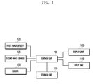
- FIG. 1 is a block diagram illustrating a configuration of an electronic device according to an embodiment of the present disclosure.
- a first image sensor 120 (e.g., a rear image sensor) may be installed at the rear side of the device, and a second image sensor 125 (e.g., a front image sensor) may be installed in a bezel of the front side of the device.
- the first image sensor 120 may be an image sensor having a higher number of pixels than that of the second image sensor 125.
- the first image sensor 120 and second image sensor 125 may independently or simultaneously be driven under the control of a control unit 100. Further, the first image sensor 120 and second image sensor 125 may photograph a still or a moving image under the control of control unit 100.
- the control unit 100 controls the general operation of the electronic device.
- the control unit 100 may drive the first image sensor 120 and/or the second image sensor 125 independently or simultaneously, control to display photographed images in a dual screen having a main screen and a sub screen when the image sensors are driven according to an embodiment of the present disclosure, and control a photographing and editing of the dual screen.
- the sub screen may be a PIP screen.
- a storage unit 110 may be equipped with a program memory for storing an operation program and programs according to embodiments of the present disclosure, and a data memory for storing photographed images.
- a display unit 130 may be installed at the front side of the device together with the second image sensor 125, and may display images photographed by the first image sensor 120 and/or second image sensor 125 under the control of the control unit 100.
- the display unit 130 may be a Liquid Crystal Display (LCD) or an Organic Light Emitting Diode (OLED) type display.
- An input unit 140 may generate input signals for controlling a photographing operation of the electronic device.
- the display unit 130 and the input unit 140 may be integrated into a touch screen.
- a sensor 150 may include at least one sensor to detect the state of the electronic device.
- the sensor may be a geomagnetic sensor, an acceleration sensor, a gyro sensor, and the like, and generate a signal for detecting a change of device state according to a motion of the electronic device, such as a rotation, an orientation, and the like to output to the control unit 100.
- the control unit 100 of the electronic device having the above configuration may obtain a plurality of images by simultaneously driving the first image sensor 120 and second image sensor 125, and display the obtained images in a main screen and a sub screen of the display unit 130.
- the control unit 100 may change the main screen and the sub screen according to a user's selection.
- the electronic device may photograph by simultaneously or sequentially driving the first image sensor 120 and second image sensor 125 if photographing (dual shot) is requested in a dual mode, and generate a still image by synthesizing the photographed main screen and sub screen image.
- the electronic device having a first image sensor 120 and a second image sensor 125 generally photographs a main screen (e.g., landscape and/or portrait as a first image) by using the first image sensor 120 and photographs a photographer (e.g., the user as a second image) by using the second image sensor 125.
- the user can identify a first image being photographed by the first image sensor 120 and a second image being photographed by the second image sensor 125 through the display unit 130.
- the sub screen may be fixed to a specific location of the display unit 130. In this case, if the distance between the display positions of the sub screen and the second image sensor 125 is great, a second image having a desired eye direction cannot be easily obtained.
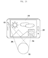
- FIGS. 2A to 2C are drawings illustrating a procedure of obtaining and processing a second image in a dual photographing mode according to an embodiment of the present disclosure.
- the control unit 100 may display a first image photographed by the first image sensor 120 in a main screen 210 and a second image photographed by the second image sensor 125 in a sub screen 220.
- the control unit 100 may set a display area of the sub screen 220 to display the second image photographed by the second image sensor 125 in the lower right area of the display unit 130 as shown in FIG. 2A .
- the second image sensor 125 and the sub screen 220 may have a great distance.
- a user 230 may take a photograph while looking at the image 210 and/or image 220 displayed in the display unit 130.
- a photographing angle of the second image sensor 125 is formed as shown by reference number 250, and thereby a user can see the sub screen 220 photographed as shown by reference number 255. Accordingly, if the second image sensor 125 and the sub screen 220 are located at a great distance, an angle difference is generated between an area 250 actually photographed by the image sensor 125 and an area 255 at which the user 230 looks, and thereby an image photographed by the image sensor 125 can aim at the left part of the actually photographed image. This difference becomes greater as the size of the display unit 130 increases.
- the reference number 250 indicates an area in which the second image sensor 125 actually photographs a subject (photographer), and the reference number 255 indicates an area at which the photographer looks for photographing, i.e., an area at which a face and eyes are directed.
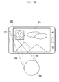
- FIG. 2B illustrates an example of locating the display position of the sub screen 220 close to the second image sensor 125 according to an embodiment of the present disclosure. As shown in FIG. 2B , the difference between the area 255 at which the user 230 looks and the area 250 of actual photographing becomes smaller, and thereby the user 230 can photograph in a pleasant condition. In fig.
- the sub screen 220 is displayed in an upper, left quadrant of the display screen, that quadrant being the quadrant corresponding to (i.e. closest to, or next to) the position of the second image sensor 125 when the device is in the illustrated orientation.
- the illustrated position of the sub screen 220 can also be described as being in the upper half of the overall screen, and in the left hand third of the screen in this example.
- control unit 100 detects a device state (e.g., rotation, location, etc.) through the sensor 150 in a preview mode, identifies a state of the second image sensor 125 according to the detected location of the device, and displays a sub screen 200 by moving the display position of the sub screen 220 closer to the second image sensor 125 as shown in FIG. 2B .
- a device state e.g., rotation, location, etc.
- the control unit 100 detects it, and stores images in the storage unit 110 by capturing and synthesizing (or in other words combining) the first image output by the first image sensor 120 and the second image output by the second image sensor 125. If the display position of the sub screen 220 is changed according to the location of the second image sensor 125, the location of sub screen 220 synthesized (combined) into the main screen 210 may change. In this case, the control unit 100 may synthesize (combine) and store the second image as displayed in the preview mode as shown in FIG. 2B , or synthesize and store by moving the image of sub screen 220 as shown in FIG. 2A .
- a photographing command e.g., shutter switch on
- the control unit 100 stores a dual image shown in FIG. 2B by synthesizing as shown in FIG. 2A .
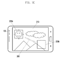
- the control unit 100 may apply an effect of moving the second image in the display unit 130.
- a sub screen image shown by 220a is located at 220b by moving along the arrow mark 260 (for example, animation), and an actually stored sub screen image may be displayed in the main screen image 210 as shown by 220b.
- the control unit 100 can display the dual image stored in the storage unit 110 through the display unit 130.
- the control unit 100 may display an original location of the sub screen to be synthesized. For example, as shown in FIG. 2C , the control unit 100 may display a location of the sub screen to be synthesized as shown by 220b in the state of displaying the sub screen 220a in a location closer to the second image sensor 125.
- the location 220b for synthesizing the sub screen image may be displayed in an image frame.
- the image frame may be expressed with a border line (for example, dotted line), or the inner part or border line of the image frame may be displayed in a different color.
- a user may provide an input or inputs to the device to move the position of the sub screen in the overall screen to a desired position, and then capture an image comprising the main screen and the sub screen superimposed, or synthesized, on the main screen at the desired position.
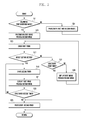
- FIG. 3 is a flowchart illustrating a procedure of photographing an image in an electronic device according to an embodiment of the present disclosure.
- the control unit 100 detects the request at operation 311, and identifies the location of the second image sensor 125 by analyzing the location of device from an output of the sensor 150 at operation 313. Subsequently, the control unit 100 sets a display area of the second image (i.e., display area of the sub screen) at a location closer to the identified location of the second image sensor 125 at operation 315.
- a display area of the second image i.e., display area of the sub screen
- FIG. 4 is a drawing illustrating a method of deciding a location of a sub screen display area in which a second image is photographed by a second image sensor according to an embodiment of the present disclosure.
- the control unit 100 analyzes a state (e.g., rotation) of a device by using an output of the sensor 150 in a dual mode, and can determine the location of the second image sensor 125 according to the identified state of the device.
- the device can have four states 410, 420, 430 and 440 as shown in FIG. 4 .
- the device states 410 and 430 illustrate examples of a landscape display mode
- the device states 420 and 440 illustrate examples of a portrait display mode.
- the device state 430 of FIG. 4 illustrates a state in which the device state 410 is rotated by 180 degrees, and if the device is rotated by 180 degrees, the second image sensor 125 becomes located at the other side.
- the control unit 100 can set a display area of the sub screen 220 by moving to a location closer to the second image sensor 125 at operation 315 as shown by 410 and 430 of FIG. 4 .
- control unit 100 can perform a preview mode in the dual mode at operation 317.
- the control unit 100 drives both the first image sensor 120 and the second image sensor 125, displays a first image output by the first image sensor 120 in the main screen of the display unit 130, and displays a second image output by the second image sensor 125 in the sub screen display area set at operation 315.
- the control unit 100 may be equipped with an image processing unit (e.g., an image signal processor), and the image processing unit may include an image pre-processing unit, a post-processing unit, an image scaler, and a codec.
- the first image output by the first image sensor 120 is pre-processed and post-processed by the image processing unit, and the image scaler outputs the first image to the display unit 130 by scaling to the size of main screen.
- the second image output by the second image sensor 125 is pre-processed and post-processed by the image processing unit, and the image scaler outputs the second image to the display unit 130 by scaling to the size of the sub screen.
- the control unit 100 may select an image sensor to display a main screen image according to a user's selection. For example, a user may select an image output by the first image sensor 120 or second image sensor 125 as a main screen image by using an image sensor selection button. In this case, the control unit 100 may process an output of an image sensor selected by the user as a main screen image and an output of the other image sensor as a sub screen image. The control unit 100 processes the main screen image and outputs to the display unit 130, and processes the sub screen image and displays in a location of the main screen.
- the sub screen image may be output by resizing to a size in the main screen.
- the display position of the sub screen is changed to a location closer to the second image sensor 125, and if an output of the first image sensor 120 is selected for the sub screen, the display position of the sub screen may be fixed. Accordingly, if the output of the second image sensor 125 is selected as a sub screen image, the control unit 100 may display the first and second images in the display unit 130 in a state of 410 to 440 in FIG. 4 according to the location of the second image sensor 125.
- the control unit 100 While performing the preview mode, the control unit 100 identifies a change of the device (e.g., location, rotation, orientation, etc.) by analyzing an output of the sensor 150. If a rotation of the device is generated, the control unit 100 detects it at operation 331, and sets the display area of the sub screen 200 according to the location change of the second image sensor 125 by performing operations 313 and 315.
- a change of the device e.g., location, rotation, orientation, etc.
- the control unit 100 detects it at operation 319, and captures a first image output by the first image sensor 120 and a second image output by the second image sensor 125 at operation 321.
- the operation of capturing the first image and second image may be performed in a procedure as shown in FIG. 5 .
- FIG. 5 is a flowchart illustrating a procedure of photographing a first image and a second image in a dual mode according an embodiment of the present disclosure.
- the photographing in a dual mode may use a synchronous or an asynchronous photographing method which can be set in a setting mode. If the user sets an image sensor in the setting mode, the control unit 100 may display a photographing mode menu including a dual shot mode in the display unit 130. If the user selects the dual shot mode, the control unit 100 displays a dual shot menu, and the dual shot menu may display a synchronous photographing or an asynchronous photographing.
- the synchronous photographing is a photographing mode of simultaneously obtaining a first image and a second image respectively from the first image sensor 120 and the second image sensor 125
- the asynchronous photographing is a photographing mode of obtaining a sub screen image from an image sensor after obtaining a main screen image from the other image sensor. If a photographing is requested, the synchronous photographing can simultaneously process images output by the two image sensors to still images. In a dual shot photographing, the user generally sets the main screen image so as to fit a photographing composition. However, the photographing composition of sub screen image may be in an undesirable state. In this case, it may be desirable to use an asynchronous photographing method.
- the asynchronous photographing method firstly photographs by setting a main screen image to a desired photographing composition, and by setting a sub screen image to another desired photographing composition.
- the synchronous or asynchronous photographing may be selected by a user when setting a dual shot mode.
- the control unit checks the photographing mode at operation 511. If the photographing mode is a synchronous photographing mode at operation 511, the control unit 100 captures an image obtained by the currently operating image sensor (e.g., the first image sensor 120 or the second image sensor 125) at operation 531.
- the currently operating image sensor e.g., the first image sensor 120 or the second image sensor 125
- the control unit 100 performs the asynchronous photographing mode.
- the control unit 100 can guide the user by displaying the current main screen and sub screen being sequentially photographed in the display unit 130.
- the control unit 100 may photograph a main screen image and display a sub screen image in a preview state at operation 513.
- the sub screen displayed in the preview state may be an image photographed by the second image sensor 125, and the display position of the sub screen may be located closer to the second image sensor 125 as previously described.
- the control unit 100 controls the display unit 130 to display the first image of the main screen as a still image and the second image of the sub screen as a preview image.
- the control unit 100 drives a timer at operation 515, and determines whether an action is detected at operation 517. For example, the control unit 100 can capture a sub screen image if the action is detected after the timer is driven until the timer is expired.
- the action may be switching a shutter switch on (i.e., a photographing request for capturing a second image) or an operation of a device (e.g., a hovering or touch interaction of a specific area, shaking, rotating, motion of a device, etc.).
- the control unit 100 detects it at operation 527, and displays the captured first image in a main screen by processing as a still image and a second image photographed by the second image sensor 125 in a sub screen display area as a preview image at operation 529.
- the first timer driven at operation 515 may provide a time for the user to set a composition for the second image to be captured through the second image sensor 125 after capturing the main screen image.
- the control unit 100 detects it at operation 527, and captures a second image at operation 525.
- the second image may be a sub screen image. The main screen image remains in a captured state, and thereby the main screen can be displayed as a still image.
- the control unit 100 detects it at operation 517, and drives a second timer at operation 519.
- the second timer driven at operation 519 provides a time for the user to set a composition of a second image to be captured by the second image sensor 125 since the action is performed.
- the period of the second timer driven at operation 519 may be identical to that of the first timer or different from that of the first timer.
- the control unit 100 displays the captured first image in a main screen by processing to a still image and a second image photographed by the second image sensor 125 in a sub screen display area as a preview image at operation 521. If the first timer expires, the control unit 100 detects it at operation 523, and captures a second image at operation 525.
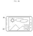
- FIGS. 6A and 6B are drawings illustrating a movement of a location of a sub screen display area according to an embodiment of the present disclosure.
- the control unit 100 can capture a first image (i.e., a main screen image) output by the first image sensor 120 and a second image (i.e., a sub screen image) output by the second image sensor 125.
- the sub screen image is variably set according to the location of the second image sensor 125 in the preview mode as shown in FIG. 6A , and if a photographing is requested, the control unit 100 can capture a second image from a location adjacent to the second image sensor 125 (i.e., capture position).
- the control unit 100 can synthesize the captured sub screen image in a location of the sub screen (i.e., save position) as shown in FIG. 6B . Accordingly, the control unit 100 captures a first image and a second image at a capture position according to operation 321 of FIG. 3 and the procedure of FIG. 5 , moves the second image captured at operation 323 of FIG. 3 to a sub screen location (i.e., save position) as shown in FIG. 6B , and stores the second image after synthesizing with the first image at operation 325.
- the control unit 100 may or may not display a movement of the second image to a sub screen location in the display unit 130 at operation 323.
- control unit 100 determines if the dual mode photographing is to be terminated at operation 341. If the dual mode photographing is to be terminated, the control unit 100 terminates the dual mode photographing at operation 343. Otherwise, the control unit 100 returns to operation 317.
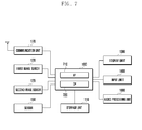
- FIG. 7 is block diagram illustrating a configuration of portable terminal operating according to an embodiment of the present disclosure.
- the portable terminal may be any of various digital equipment such as a mobile phone including a smart phone, an MP3 terminal, a tablet, a computer, and the like.
- a communication unit 170 performs a function of communicating with a base station or an internet server.
- the communication unit 170 may be configured with a transmitter for frequency up-converting and electrically amplifying a transmitting signal, and a receiver for low noise amplifying and frequency down-converting a received signal.
- the communication unit 170 may include an encoder and a decoder.
- the encoder outputs a transmitting signal to the transmitter by encoding the signal and the decoder decodes a signal received by the receiver.
- the codec (encoder + decoder) may include an LTE, WCDMA, GSM, WIFI, WIBRO, NFC, and Bluetooth. In an embodiment of the present disclosure, it is assumed that the communication unit 170 includes an LTE, WIFI, and Bluetooth.
- a first image sensor 120 is an image sensor installed at the rear side of the portable terminal, and photographs an image in a high resolution.
- a second image sensor 125 is an image sensor installed at the front side of the portable terminal, and photographs an image in a lower resolution than the first image sensor 120.
- a control unit 100 controls the general operation of the portable terminal, and may include an Application Processor (AP) 710 for controlling various applications of the portable terminal and a Communication Processor (CP) 720 for controlling a communication function of the portable terminal.
- the application processor 710 controls to process images obtained by the first image sensor 120 and second image sensor 125 in a dual mode according to an embodiment of the present disclosure, to display a second image by setting a sub screen display area at a location closer to the second image sensor 125 (capture position) in a preview mode, and to capture a second image in the location closer to the second image sensor 125 and save the second image by synthesizing in a location of a main screen (save position) in a capture mode.
- AP Application Processor
- CP Communication Processor
- a storage unit 110 may include a program memory storing an operation program of the terminal and programs according to various embodiments of the present disclosure, and a data memory storing tables for the operation of the terminal and data generated during the execution of programs.
- a display unit 130 may display information of an application being executed under the control of the control unit 100.
- the display unit 130 may display images of a main screen and a sub screen under the control of the control unit 100 in a dual image sensor mode.
- the display unit 130 may be an LCD, an OLED, and the like.
- An input unit 140 may be provided in a capacitive or resistive type, and can output location information of a user's touch (e.g., a finger touch) to the control unit 100.
- the input unit 140 may further include an EMR sensor pad, and can detect and output a pen touch input to the control unit 100.
- the display unit 130 and the input unit 140 may be configured in a integrated form.
- a sensor 150 may include various sensors for detecting a movement of the portable terminal, such as an acceleration sensor, a geomagnetic sensor, a gyro sensor, a location detecting sensor, and the like.
- An audio processing unit 180 processes a voice signal generated in a communication mode under the control of the control unit 100.
- the control unit 100 of the portable terminal controls the display unit 130 to display images output by the image sensor 120 and/or the image sensor 125.
- An image sensor button for selecting an image sensor to display a main screen image in the display unit 130 and a dual button for switching on/off the dual mode are displayed in the display unit 130. If the buttons are touched, the control unit 100 can detect an on/off state of a corresponding button through the input unit 140. Accordingly, the control unit 100 performs a dual mode to drive the first image sensor 120 and the second image sensor 125 if a user touches the dual button, and can display images output by the image sensors 120 and 125 respectively on a main screen and a sub screen of the display unit 130 as a dual image.
- the control unit 100 can select an image sensor to output a main screen image according to a user's selection of an image sensor button in the dual mode.
- the first image sensor 120 is selected for a main screen image and the second image sensor 125 is selected for a sub screen image when the portable terminal is driven in a dual mode.
- the control unit 100 can perform a dual mode.
- a preview mode of the dual mode the control unit 100 identifies a location of the second image sensor 125 as shown in FIG. 3 , and sets a sub screen display area in the display unit 130 closer to the identified location of the second image sensor 125. If the distance between the second image sensor 125 and the sub screen display area is great as shown in FIG. 2A , user's face and eyes photographed by the second image sensor 125 are directed to the sub screen display area, and thereby the photographed second image can have an unnatural posture.
- an embodiment of the present disclosure suggests an apparatus and a method for setting a sub screen display area so that a photographing angle (i.e., shooting angle) of the second image sensor 125 coincides with a direction of the user's face and eyes as shown in FIG. 2B .
- the control unit 100 may use a method of setting a sub screen display area in the display unit 130 closest to the second image sensor 125 installed at the front side of the portable terminal. If the portable terminal rotates in the preview mode, the sub screen display area moves in a rotating direction of the second image sensor 125 as shown in FIG. 4 .
- the sub screen display area set closer to the second image sensor 125 may be located at a capture position for capturing the second image.
- the control unit 100 can capture a first image and a second image using the procedure of FIG. 5 .
- the first image and the second image may be captured by a synchronous or an asynchronous photographing method, and the second image may be captured at a position closer to the second image sensor 125.
- the control unit 100 synthesizes the second image with the first image, and the synthesizing location (i.e., save position) of the second image may be a location (e.g., the lower left side of the main screen image as in FIG. 6B ). Accordingly, the control unit can synthesize the captured second image with the first image by moving to the synthesizing location.
- the control unit 100 displays the synthesized first image and the second image respectively in a main screen and a sub screen of the display unit 130, and the synthesized image displayed in the display unit 130 may be stored in the storage unit 110.
- embodiments of the present invention can be realized in the form of hardware, software or a combination of hardware and software. Any such software may be stored in the form of volatile or non-volatile storage such as, for example, a storage device like a ROM, whether erasable or rewritable or not, or in the form of memory such as, for example, RAM, memory chips, device or integrated circuits or on an optically or magnetically readable medium such as, for example, a CD, DVD, magnetic disk or magnetic tape or the like. It will be appreciated that the storage devices and storage media are embodiments of machine-readable storage that are suitable for storing a program or programs comprising instructions that, when executed, implement embodiments of the present invention.
- embodiments provide a program comprising code for implementing apparatus or a method as claimed in any one of the claims of this specification and a machine-readable storage storing such a program. Still further, such programs may be conveyed electronically via any medium such as a communication signal carried over a wired or wireless connection and embodiments suitably encompass the same.
Landscapes
- Engineering & Computer Science (AREA)
- Multimedia (AREA)
- Signal Processing (AREA)
- Human Computer Interaction (AREA)
- Studio Devices (AREA)
- User Interface Of Digital Computer (AREA)
- Controls And Circuits For Display Device (AREA)
- Facsimiles In General (AREA)
- Image Processing (AREA)
Applications Claiming Priority (1)
| Application Number | Priority Date | Filing Date | Title |
|---|---|---|---|
| KR1020130020757A KR102032347B1 (ko) | 2013-02-26 | 2013-02-26 | 이미지 센서 위치를 이용한 이미지 영역 설정 장치 및 방법 |
Publications (3)
| Publication Number | Publication Date |
|---|---|
| EP2770724A2 true EP2770724A2 (de) | 2014-08-27 |
| EP2770724A3 EP2770724A3 (de) | 2017-04-19 |
| EP2770724B1 EP2770724B1 (de) | 2022-11-09 |
Family
ID=50193218
Family Applications (1)
| Application Number | Title | Priority Date | Filing Date |
|---|---|---|---|
| EP14156084.7A Active EP2770724B1 (de) | 2013-02-26 | 2014-02-21 | Vorrichtung und Verfahren zur Positionierung eines Bildbereichs unter Verwendung der Bildsensorstelle |
Country Status (6)
| Country | Link |
|---|---|
| US (2) | US9674444B2 (de) |
| EP (1) | EP2770724B1 (de) |
| KR (1) | KR102032347B1 (de) |
| CN (1) | CN105103535B (de) |
| AU (1) | AU2014221568B2 (de) |
| WO (1) | WO2014133278A1 (de) |
Cited By (2)
| Publication number | Priority date | Publication date | Assignee | Title |
|---|---|---|---|---|
| EP4586629A4 (de) * | 2022-09-06 | 2025-12-10 | Douyin Vision Co Ltd | Bilderfassungsverfahren und -vorrichtung, vorrichtung und speichermedium |
| US12520033B2 (en) | 2022-07-07 | 2026-01-06 | Douyin Vision (Beijing) Co., Ltd. | Method, apparatus, device and storage medium for multimedia content shooting |
Families Citing this family (30)
| Publication number | Priority date | Publication date | Assignee | Title |
|---|---|---|---|---|
| US9741150B2 (en) | 2013-07-25 | 2017-08-22 | Duelight Llc | Systems and methods for displaying representative images |
| US20170039867A1 (en) | 2013-03-15 | 2017-02-09 | Study Social, Inc. | Mobile video presentation, digital compositing, and streaming techniques implemented via a computer network |
| US9916328B1 (en) | 2014-07-11 | 2018-03-13 | Google Llc | Providing user assistance from interaction understanding |
| US12401911B2 (en) | 2014-11-07 | 2025-08-26 | Duelight Llc | Systems and methods for generating a high-dynamic range (HDR) pixel stream |
| US12401912B2 (en) | 2014-11-17 | 2025-08-26 | Duelight Llc | System and method for generating a digital image |
| US12445736B2 (en) | 2015-05-01 | 2025-10-14 | Duelight Llc | Systems and methods for generating a digital image |
| US9936138B2 (en) * | 2015-07-29 | 2018-04-03 | Samsung Electronics Co., Ltd. | User terminal apparatus and control method thereof |
| US11284003B2 (en) | 2015-07-29 | 2022-03-22 | Samsung Electronics Co., Ltd. | User terminal apparatus and control method thereof |
| WO2017195034A1 (en) * | 2016-05-07 | 2017-11-16 | Smart Third-I Ltd | Systems and methods involving edge camera assemblies in handheld devices |
| US9832368B1 (en) * | 2016-05-31 | 2017-11-28 | Motorola Mobility Llc | Managing unintended camera clicks |
| US9876957B2 (en) * | 2016-06-21 | 2018-01-23 | Hand Held Products, Inc. | Dual mode image sensor and method of using same |
| KR20180023310A (ko) * | 2016-08-25 | 2018-03-07 | 엘지전자 주식회사 | 이동 단말기 및 그 제어방법 |
| CN107592459A (zh) * | 2017-09-22 | 2018-01-16 | 维沃移动通信有限公司 | 一种拍照方法及移动终端 |
| JP2019080166A (ja) * | 2017-10-24 | 2019-05-23 | 株式会社東芝 | 画像処理装置、及び制御方法 |
| CN108200332A (zh) * | 2017-12-27 | 2018-06-22 | 努比亚技术有限公司 | 一种拼图方法、移动终端及计算机可读存储介质 |
| CN108234891B (zh) * | 2018-04-04 | 2019-11-05 | 维沃移动通信有限公司 | 一种拍照方法及移动终端 |
| JP7183597B2 (ja) * | 2018-07-12 | 2022-12-06 | 京セラドキュメントソリューションズ株式会社 | プレビュー画像表示装置及びプレビュー画像表示プログラム |
| CN111586282B (zh) * | 2019-02-18 | 2021-08-10 | 北京小米移动软件有限公司 | 拍摄方法、装置、终端及可读存储介质 |
| US11409434B2 (en) | 2019-06-30 | 2022-08-09 | Lenovo (Beijing) Co., Ltd. | Image collection and processing method, apparatus, and storage medium |
| CN110266983A (zh) * | 2019-06-30 | 2019-09-20 | 联想(北京)有限公司 | 一种图像处理方法、设备及存储介质 |
| CN110505428B (zh) * | 2019-08-28 | 2021-06-15 | 联想(北京)有限公司 | 一种信息处理方法及电子设备 |
| CN110784674B (zh) | 2019-10-30 | 2022-03-15 | 北京字节跳动网络技术有限公司 | 视频处理的方法、装置、终端及存储介质 |
| WO2021083146A1 (zh) | 2019-10-30 | 2021-05-06 | 北京字节跳动网络技术有限公司 | 视频处理方法、装置、终端及存储介质 |
| US20210144297A1 (en) * | 2019-11-12 | 2021-05-13 | Shawn Glidden | Methods System and Device for Safe-Selfie |
| US11297260B1 (en) | 2020-11-20 | 2022-04-05 | Donald Siu | Techniques for capturing video in landscape mode by a handheld device |
| JP7287379B2 (ja) * | 2020-12-10 | 2023-06-06 | セイコーエプソン株式会社 | 表示方法、検出装置、および、プログラム |
| US12386487B2 (en) | 2022-05-23 | 2025-08-12 | Snap Inc. | Unlocking sharing destinations in an interaction system |
| CN117425065A (zh) * | 2022-07-06 | 2024-01-19 | 荣耀终端有限公司 | 一种拍摄方法及相关设备 |
| CN117407596A (zh) | 2022-07-07 | 2024-01-16 | 抖音视界(北京)有限公司 | 用于内容呈现的方法、装置、设备和存储介质 |
| CN120282011B (zh) * | 2023-12-29 | 2026-04-21 | 荣耀终端股份有限公司 | 拍摄方法及相关电子设备 |
Family Cites Families (36)
| Publication number | Priority date | Publication date | Assignee | Title |
|---|---|---|---|---|
| JPH09107531A (ja) | 1995-10-09 | 1997-04-22 | Matsushita Electric Ind Co Ltd | ビデオ会議システム |
| JPH11225319A (ja) * | 1998-02-09 | 1999-08-17 | Olympus Optical Co Ltd | 画像入出力装置 |
| US6867807B2 (en) * | 2001-09-04 | 2005-03-15 | Eastman Kodak Company | Camera having single-button timed display of most-recently viewed image and default display of last verification image and method |
| JP2003189168A (ja) | 2001-12-21 | 2003-07-04 | Nec Corp | 携帯電話用カメラ |
| JP2004062565A (ja) | 2002-07-30 | 2004-02-26 | Canon Inc | 画像処理装置及び方法並びにプログラム記憶媒体 |
| JP2004145291A (ja) | 2002-10-03 | 2004-05-20 | Casio Comput Co Ltd | 画像表示装置、画像表示方法及びプログラム |
| JP3948387B2 (ja) | 2002-10-24 | 2007-07-25 | 松下電器産業株式会社 | ディジタルカメラおよびディジタルカメラ付き携帯電話装置 |
| JP3757931B2 (ja) * | 2002-11-28 | 2006-03-22 | 松下電器産業株式会社 | 電子カメラおよび電子カメラ付き携帯電話装置 |
| KR100663478B1 (ko) | 2003-01-30 | 2007-01-02 | 삼성전자주식회사 | 휴대단말기의 화면표시 장치 및 방법 |
| JP2004260433A (ja) | 2003-02-25 | 2004-09-16 | Hitachi Ltd | ビデオカメラ付き携帯電話機 |
| KR100566184B1 (ko) | 2005-04-22 | 2006-03-29 | 삼성전자주식회사 | 이동통신단말기에서 이미지를 표시하는 방법 및 그이동통신단말기 |
| US20080084482A1 (en) | 2006-10-04 | 2008-04-10 | Sony Ericsson Mobile Communications Ab | Image-capturing system and method |
| KR101335626B1 (ko) | 2007-01-03 | 2013-12-03 | 삼성전자주식회사 | 사용자의 얼굴이 모니터링되는 디지털 영상 처리 장치 |
| JP4853425B2 (ja) | 2007-08-14 | 2012-01-11 | ソニー株式会社 | 撮像装置、撮像方法およびプログラム |
| KR101405948B1 (ko) | 2007-10-22 | 2014-06-12 | 엘지전자 주식회사 | 이동 단말기 및 이동 단말기의 화면 표시 방법 |
| US7880807B2 (en) | 2007-12-26 | 2011-02-01 | Sony Ericsson Mobile Communications Ab | Camera system with mirror arrangement for generating self-portrait panoramic pictures |
| ES2313860B1 (es) | 2008-08-08 | 2010-03-16 | Nilo Garcia Manchado | Camara digital y procedimiento asociado. |
| KR20100071754A (ko) | 2008-12-19 | 2010-06-29 | 삼성전자주식회사 | 터치와 키조작에 의한 멀티 입력 방식을 이용한 촬영방법 및 이를 적용한 촬영장치 |
| KR101255284B1 (ko) | 2008-12-29 | 2013-04-15 | 엘지디스플레이 주식회사 | 액정표시장치 |
| KR101649098B1 (ko) | 2009-06-30 | 2016-08-19 | 삼성전자주식회사 | 휴대용 단말기에서 센서를 이용한 렌더링 방법 및 장치 |
| JP5423183B2 (ja) | 2009-07-03 | 2014-02-19 | ソニー株式会社 | 表示制御装置および表示制御方法 |
| KR101594295B1 (ko) | 2009-07-07 | 2016-02-16 | 삼성전자주식회사 | 촬영 장치 및 촬영 방법 |
| CN102055834B (zh) * | 2009-10-30 | 2013-12-11 | Tcl集团股份有限公司 | 一种移动终端的双摄像头拍照方法 |
| JP2011166442A (ja) | 2010-02-09 | 2011-08-25 | Sanyo Electric Co Ltd | 撮像装置 |
| US9264659B2 (en) * | 2010-04-07 | 2016-02-16 | Apple Inc. | Video conference network management for a mobile device |
| US9584735B2 (en) | 2010-11-12 | 2017-02-28 | Arcsoft, Inc. | Front and back facing cameras |
| US8687807B2 (en) * | 2011-01-26 | 2014-04-01 | Nagrastar, L.L.C. | Cascading dynamic crypto periods |
| KR101764372B1 (ko) * | 2011-04-19 | 2017-08-03 | 삼성전자주식회사 | 휴대용 단말기에서 영상 합성 방법 및 장치 |
| US8988558B2 (en) * | 2011-04-26 | 2015-03-24 | Omnivision Technologies, Inc. | Image overlay in a mobile device |
| KR20130010590A (ko) * | 2011-07-19 | 2013-01-29 | 엘지전자 주식회사 | 전자기기 및 전자기기의 동작 방법 |
| CN102938796A (zh) * | 2011-08-15 | 2013-02-20 | 中兴通讯股份有限公司 | 一种手机 |
| US20130120602A1 (en) | 2011-11-14 | 2013-05-16 | Microsoft Corporation | Taking Photos With Multiple Cameras |
| US20130155308A1 (en) | 2011-12-20 | 2013-06-20 | Qualcomm Incorporated | Method and apparatus to enhance details in an image |
| KR101864452B1 (ko) | 2012-01-12 | 2018-06-04 | 삼성전자주식회사 | 이미지 촬영 및 화상 통화 장치와 방법 |
| US8866943B2 (en) | 2012-03-09 | 2014-10-21 | Apple Inc. | Video camera providing a composite video sequence |
| KR101545883B1 (ko) | 2012-10-30 | 2015-08-20 | 삼성전자주식회사 | 단말의 카메라 제어 방법 및 그 단말 |
-
2013
- 2013-02-26 KR KR1020130020757A patent/KR102032347B1/ko active Active
-
2014
- 2014-02-12 US US14/178,797 patent/US9674444B2/en active Active
- 2014-02-18 CN CN201480010711.5A patent/CN105103535B/zh active Active
- 2014-02-18 AU AU2014221568A patent/AU2014221568B2/en not_active Ceased
- 2014-02-18 WO PCT/KR2014/001302 patent/WO2014133278A1/en not_active Ceased
- 2014-02-21 EP EP14156084.7A patent/EP2770724B1/de active Active
-
2017
- 2017-06-05 US US15/614,116 patent/US10136069B2/en active Active
Non-Patent Citations (1)
| Title |
|---|
| None |
Cited By (2)
| Publication number | Priority date | Publication date | Assignee | Title |
|---|---|---|---|---|
| US12520033B2 (en) | 2022-07-07 | 2026-01-06 | Douyin Vision (Beijing) Co., Ltd. | Method, apparatus, device and storage medium for multimedia content shooting |
| EP4586629A4 (de) * | 2022-09-06 | 2025-12-10 | Douyin Vision Co Ltd | Bilderfassungsverfahren und -vorrichtung, vorrichtung und speichermedium |
Also Published As
| Publication number | Publication date |
|---|---|
| CN105103535B (zh) | 2019-06-07 |
| EP2770724B1 (de) | 2022-11-09 |
| WO2014133278A1 (en) | 2014-09-04 |
| KR20140106333A (ko) | 2014-09-03 |
| CN105103535A (zh) | 2015-11-25 |
| AU2014221568A1 (en) | 2015-07-16 |
| EP2770724A3 (de) | 2017-04-19 |
| US10136069B2 (en) | 2018-11-20 |
| AU2014221568B2 (en) | 2017-03-23 |
| US20140240543A1 (en) | 2014-08-28 |
| US20170272659A1 (en) | 2017-09-21 |
| US9674444B2 (en) | 2017-06-06 |
| KR102032347B1 (ko) | 2019-10-15 |
Similar Documents
| Publication | Publication Date | Title |
|---|---|---|
| EP2770724B1 (de) | Vorrichtung und Verfahren zur Positionierung eines Bildbereichs unter Verwendung der Bildsensorstelle | |
| US11012639B2 (en) | Apparatus and method for processing an image in device | |
| US9992410B2 (en) | Apparatus and method photographing image | |
| KR102114377B1 (ko) | 전자 장치에 의해 촬영된 이미지들을 프리뷰하는 방법 및 이를 위한 전자 장치 | |
| CN105827952B (zh) | 一种去除指定对象的拍照方法及移动终端 | |
| CN106027907B (zh) | 一种自动调整摄像头的方法及移动终端 | |
| WO2024051556A1 (zh) | 壁纸显示的方法、电子设备及存储介质 | |
| CN101562703A (zh) | 用于在成像设备内执行基于触摸的调整的方法和装置 | |
| EP4195647A1 (de) | Bildverarbeitungsverfahren, mobiles endgerät und speichermedium | |
| CN107172347B (zh) | 一种拍照方法及终端 | |
| US20130342729A1 (en) | Method and apparatus for processing image data in terminal | |
| KR20160088719A (ko) | 이미지를 촬영하는 전자 장치 및 방법 | |
| KR102076629B1 (ko) | 휴대 장치에 의해 촬영된 이미지들을 편집하는 방법 및 이를 위한 휴대 장치 | |
| KR102241840B1 (ko) | 이미지 촬영장치 및 방법 | |
| JP6519205B2 (ja) | プログラム、情報処理装置及び処理方法 | |
| JP2016081302A (ja) | 表示制御装置、その制御方法、プログラム、及び記録媒体 | |
| KR20140089134A (ko) | 듀얼 카메라를 구비하는 장치의 이미지 처리 장치 및 방법 |
Legal Events
| Date | Code | Title | Description |
|---|---|---|---|
| PUAI | Public reference made under article 153(3) epc to a published international application that has entered the european phase |
Free format text: ORIGINAL CODE: 0009012 |
|
| 17P | Request for examination filed |
Effective date: 20140221 |
|
| AK | Designated contracting states |
Kind code of ref document: A2 Designated state(s): AL AT BE BG CH CY CZ DE DK EE ES FI FR GB GR HR HU IE IS IT LI LT LU LV MC MK MT NL NO PL PT RO RS SE SI SK SM TR |
|
| AX | Request for extension of the european patent |
Extension state: BA ME |
|
| PUAL | Search report despatched |
Free format text: ORIGINAL CODE: 0009013 |
|
| AK | Designated contracting states |
Kind code of ref document: A3 Designated state(s): AL AT BE BG CH CY CZ DE DK EE ES FI FR GB GR HR HU IE IS IT LI LT LU LV MC MK MT NL NO PL PT RO RS SE SI SK SM TR |
|
| AX | Request for extension of the european patent |
Extension state: BA ME |
|
| RIC1 | Information provided on ipc code assigned before grant |
Ipc: H04N 5/272 20060101ALI20170313BHEP Ipc: H04N 5/232 20060101ALI20170313BHEP Ipc: H04N 5/225 20060101AFI20170313BHEP |
|
| STAA | Information on the status of an ep patent application or granted ep patent |
Free format text: STATUS: REQUEST FOR EXAMINATION WAS MADE |
|
| R17P | Request for examination filed (corrected) |
Effective date: 20170718 |
|
| STAA | Information on the status of an ep patent application or granted ep patent |
Free format text: STATUS: EXAMINATION IS IN PROGRESS |
|
| 17Q | First examination report despatched |
Effective date: 20200814 |
|
| GRAP | Despatch of communication of intention to grant a patent |
Free format text: ORIGINAL CODE: EPIDOSNIGR1 |
|
| STAA | Information on the status of an ep patent application or granted ep patent |
Free format text: STATUS: GRANT OF PATENT IS INTENDED |
|
| INTG | Intention to grant announced |
Effective date: 20220603 |
|
| RIN1 | Information on inventor provided before grant (corrected) |
Inventor name: CHOI, HONGSUK Inventor name: KIM, MOONSOO |
|
| GRAS | Grant fee paid |
Free format text: ORIGINAL CODE: EPIDOSNIGR3 |
|
| GRAA | (expected) grant |
Free format text: ORIGINAL CODE: 0009210 |
|
| STAA | Information on the status of an ep patent application or granted ep patent |
Free format text: STATUS: THE PATENT HAS BEEN GRANTED |
|
| AK | Designated contracting states |
Kind code of ref document: B1 Designated state(s): AL AT BE BG CH CY CZ DE DK EE ES FI FR GB GR HR HU IE IS IT LI LT LU LV MC MK MT NL NO PL PT RO RS SE SI SK SM TR |
|
| REG | Reference to a national code |
Ref country code: GB Ref legal event code: FG4D |
|
| REG | Reference to a national code |
Ref country code: CH Ref legal event code: EP Ref country code: AT Ref legal event code: REF Ref document number: 1531100 Country of ref document: AT Kind code of ref document: T Effective date: 20221115 |
|
| REG | Reference to a national code |
Ref country code: DE Ref legal event code: R079 Ref document number: 602014085458 Country of ref document: DE Free format text: PREVIOUS MAIN CLASS: H04N0005225000 Ipc: H04N0023000000 |
|
| REG | Reference to a national code |
Ref country code: IE Ref legal event code: FG4D |
|
| REG | Reference to a national code |
Ref country code: DE Ref legal event code: R096 Ref document number: 602014085458 Country of ref document: DE |
|
| REG | Reference to a national code |
Ref country code: NL Ref legal event code: FP |
|
| REG | Reference to a national code |
Ref country code: LT Ref legal event code: MG9D |
|
| REG | Reference to a national code |
Ref country code: AT Ref legal event code: MK05 Ref document number: 1531100 Country of ref document: AT Kind code of ref document: T Effective date: 20221109 |
|
| PG25 | Lapsed in a contracting state [announced via postgrant information from national office to epo] |
Ref country code: SE Free format text: LAPSE BECAUSE OF FAILURE TO SUBMIT A TRANSLATION OF THE DESCRIPTION OR TO PAY THE FEE WITHIN THE PRESCRIBED TIME-LIMIT Effective date: 20221109 Ref country code: PT Free format text: LAPSE BECAUSE OF FAILURE TO SUBMIT A TRANSLATION OF THE DESCRIPTION OR TO PAY THE FEE WITHIN THE PRESCRIBED TIME-LIMIT Effective date: 20230309 Ref country code: NO Free format text: LAPSE BECAUSE OF FAILURE TO SUBMIT A TRANSLATION OF THE DESCRIPTION OR TO PAY THE FEE WITHIN THE PRESCRIBED TIME-LIMIT Effective date: 20230209 Ref country code: LT Free format text: LAPSE BECAUSE OF FAILURE TO SUBMIT A TRANSLATION OF THE DESCRIPTION OR TO PAY THE FEE WITHIN THE PRESCRIBED TIME-LIMIT Effective date: 20221109 Ref country code: FI Free format text: LAPSE BECAUSE OF FAILURE TO SUBMIT A TRANSLATION OF THE DESCRIPTION OR TO PAY THE FEE WITHIN THE PRESCRIBED TIME-LIMIT Effective date: 20221109 Ref country code: ES Free format text: LAPSE BECAUSE OF FAILURE TO SUBMIT A TRANSLATION OF THE DESCRIPTION OR TO PAY THE FEE WITHIN THE PRESCRIBED TIME-LIMIT Effective date: 20221109 Ref country code: AT Free format text: LAPSE BECAUSE OF FAILURE TO SUBMIT A TRANSLATION OF THE DESCRIPTION OR TO PAY THE FEE WITHIN THE PRESCRIBED TIME-LIMIT Effective date: 20221109 |
|
| PG25 | Lapsed in a contracting state [announced via postgrant information from national office to epo] |
Ref country code: RS Free format text: LAPSE BECAUSE OF FAILURE TO SUBMIT A TRANSLATION OF THE DESCRIPTION OR TO PAY THE FEE WITHIN THE PRESCRIBED TIME-LIMIT Effective date: 20221109 Ref country code: PL Free format text: LAPSE BECAUSE OF FAILURE TO SUBMIT A TRANSLATION OF THE DESCRIPTION OR TO PAY THE FEE WITHIN THE PRESCRIBED TIME-LIMIT Effective date: 20221109 Ref country code: LV Free format text: LAPSE BECAUSE OF FAILURE TO SUBMIT A TRANSLATION OF THE DESCRIPTION OR TO PAY THE FEE WITHIN THE PRESCRIBED TIME-LIMIT Effective date: 20221109 Ref country code: IS Free format text: LAPSE BECAUSE OF FAILURE TO SUBMIT A TRANSLATION OF THE DESCRIPTION OR TO PAY THE FEE WITHIN THE PRESCRIBED TIME-LIMIT Effective date: 20230309 Ref country code: HR Free format text: LAPSE BECAUSE OF FAILURE TO SUBMIT A TRANSLATION OF THE DESCRIPTION OR TO PAY THE FEE WITHIN THE PRESCRIBED TIME-LIMIT Effective date: 20221109 Ref country code: GR Free format text: LAPSE BECAUSE OF FAILURE TO SUBMIT A TRANSLATION OF THE DESCRIPTION OR TO PAY THE FEE WITHIN THE PRESCRIBED TIME-LIMIT Effective date: 20230210 |
|
| PG25 | Lapsed in a contracting state [announced via postgrant information from national office to epo] |
Ref country code: SM Free format text: LAPSE BECAUSE OF FAILURE TO SUBMIT A TRANSLATION OF THE DESCRIPTION OR TO PAY THE FEE WITHIN THE PRESCRIBED TIME-LIMIT Effective date: 20221109 Ref country code: RO Free format text: LAPSE BECAUSE OF FAILURE TO SUBMIT A TRANSLATION OF THE DESCRIPTION OR TO PAY THE FEE WITHIN THE PRESCRIBED TIME-LIMIT Effective date: 20221109 Ref country code: EE Free format text: LAPSE BECAUSE OF FAILURE TO SUBMIT A TRANSLATION OF THE DESCRIPTION OR TO PAY THE FEE WITHIN THE PRESCRIBED TIME-LIMIT Effective date: 20221109 Ref country code: DK Free format text: LAPSE BECAUSE OF FAILURE TO SUBMIT A TRANSLATION OF THE DESCRIPTION OR TO PAY THE FEE WITHIN THE PRESCRIBED TIME-LIMIT Effective date: 20221109 Ref country code: CZ Free format text: LAPSE BECAUSE OF FAILURE TO SUBMIT A TRANSLATION OF THE DESCRIPTION OR TO PAY THE FEE WITHIN THE PRESCRIBED TIME-LIMIT Effective date: 20221109 |
|
| REG | Reference to a national code |
Ref country code: DE Ref legal event code: R097 Ref document number: 602014085458 Country of ref document: DE |
|
| PG25 | Lapsed in a contracting state [announced via postgrant information from national office to epo] |
Ref country code: SK Free format text: LAPSE BECAUSE OF FAILURE TO SUBMIT A TRANSLATION OF THE DESCRIPTION OR TO PAY THE FEE WITHIN THE PRESCRIBED TIME-LIMIT Effective date: 20221109 Ref country code: AL Free format text: LAPSE BECAUSE OF FAILURE TO SUBMIT A TRANSLATION OF THE DESCRIPTION OR TO PAY THE FEE WITHIN THE PRESCRIBED TIME-LIMIT Effective date: 20221109 |
|
| PLBE | No opposition filed within time limit |
Free format text: ORIGINAL CODE: 0009261 |
|
| STAA | Information on the status of an ep patent application or granted ep patent |
Free format text: STATUS: NO OPPOSITION FILED WITHIN TIME LIMIT |
|
| PG25 | Lapsed in a contracting state [announced via postgrant information from national office to epo] |
Ref country code: MC Free format text: LAPSE BECAUSE OF FAILURE TO SUBMIT A TRANSLATION OF THE DESCRIPTION OR TO PAY THE FEE WITHIN THE PRESCRIBED TIME-LIMIT Effective date: 20221109 |
|
| REG | Reference to a national code |
Ref country code: CH Ref legal event code: PL |
|
| 26N | No opposition filed |
Effective date: 20230810 |
|
| REG | Reference to a national code |
Ref country code: BE Ref legal event code: MM Effective date: 20230228 |
|
| PG25 | Lapsed in a contracting state [announced via postgrant information from national office to epo] |
Ref country code: LU Free format text: LAPSE BECAUSE OF NON-PAYMENT OF DUE FEES Effective date: 20230221 Ref country code: LI Free format text: LAPSE BECAUSE OF NON-PAYMENT OF DUE FEES Effective date: 20230228 Ref country code: CH Free format text: LAPSE BECAUSE OF NON-PAYMENT OF DUE FEES Effective date: 20230228 |
|
| PG25 | Lapsed in a contracting state [announced via postgrant information from national office to epo] |
Ref country code: SI Free format text: LAPSE BECAUSE OF FAILURE TO SUBMIT A TRANSLATION OF THE DESCRIPTION OR TO PAY THE FEE WITHIN THE PRESCRIBED TIME-LIMIT Effective date: 20221109 |
|
| REG | Reference to a national code |
Ref country code: IE Ref legal event code: MM4A |
|
| PG25 | Lapsed in a contracting state [announced via postgrant information from national office to epo] |
Ref country code: IE Free format text: LAPSE BECAUSE OF NON-PAYMENT OF DUE FEES Effective date: 20230221 Ref country code: FR Free format text: LAPSE BECAUSE OF NON-PAYMENT OF DUE FEES Effective date: 20230228 |
|
| PG25 | Lapsed in a contracting state [announced via postgrant information from national office to epo] |
Ref country code: BE Free format text: LAPSE BECAUSE OF NON-PAYMENT OF DUE FEES Effective date: 20230228 |
|
| PGFP | Annual fee paid to national office [announced via postgrant information from national office to epo] |
Ref country code: NL Payment date: 20240123 Year of fee payment: 11 |
|
| PGFP | Annual fee paid to national office [announced via postgrant information from national office to epo] |
Ref country code: GB Payment date: 20240122 Year of fee payment: 11 |
|
| PG25 | Lapsed in a contracting state [announced via postgrant information from national office to epo] |
Ref country code: IT Free format text: LAPSE BECAUSE OF FAILURE TO SUBMIT A TRANSLATION OF THE DESCRIPTION OR TO PAY THE FEE WITHIN THE PRESCRIBED TIME-LIMIT Effective date: 20221109 |
|
| PG25 | Lapsed in a contracting state [announced via postgrant information from national office to epo] |
Ref country code: BG Free format text: LAPSE BECAUSE OF FAILURE TO SUBMIT A TRANSLATION OF THE DESCRIPTION OR TO PAY THE FEE WITHIN THE PRESCRIBED TIME-LIMIT Effective date: 20221109 |
|
| PG25 | Lapsed in a contracting state [announced via postgrant information from national office to epo] |
Ref country code: BG Free format text: LAPSE BECAUSE OF FAILURE TO SUBMIT A TRANSLATION OF THE DESCRIPTION OR TO PAY THE FEE WITHIN THE PRESCRIBED TIME-LIMIT Effective date: 20221109 |
|
| PG25 | Lapsed in a contracting state [announced via postgrant information from national office to epo] |
Ref country code: CY Free format text: LAPSE BECAUSE OF FAILURE TO SUBMIT A TRANSLATION OF THE DESCRIPTION OR TO PAY THE FEE WITHIN THE PRESCRIBED TIME-LIMIT; INVALID AB INITIO Effective date: 20140221 |
|
| PG25 | Lapsed in a contracting state [announced via postgrant information from national office to epo] |
Ref country code: HU Free format text: LAPSE BECAUSE OF FAILURE TO SUBMIT A TRANSLATION OF THE DESCRIPTION OR TO PAY THE FEE WITHIN THE PRESCRIBED TIME-LIMIT; INVALID AB INITIO Effective date: 20140221 |
|
| REG | Reference to a national code |
Ref country code: NL Ref legal event code: MM Effective date: 20250301 |
|
| GBPC | Gb: european patent ceased through non-payment of renewal fee |
Effective date: 20250221 |
|
| PG25 | Lapsed in a contracting state [announced via postgrant information from national office to epo] |
Ref country code: NL Free format text: LAPSE BECAUSE OF NON-PAYMENT OF DUE FEES Effective date: 20250301 |
|
| PG25 | Lapsed in a contracting state [announced via postgrant information from national office to epo] |
Ref country code: TR Free format text: LAPSE BECAUSE OF FAILURE TO SUBMIT A TRANSLATION OF THE DESCRIPTION OR TO PAY THE FEE WITHIN THE PRESCRIBED TIME-LIMIT Effective date: 20221109 |
|
| PG25 | Lapsed in a contracting state [announced via postgrant information from national office to epo] |
Ref country code: GB Free format text: LAPSE BECAUSE OF NON-PAYMENT OF DUE FEES Effective date: 20250221 |
|
| PGFP | Annual fee paid to national office [announced via postgrant information from national office to epo] |
Ref country code: DE Payment date: 20260120 Year of fee payment: 13 |