EP2770146A1 - An improved pivot hinge fitting and a roof window comprising such a hinge fitting - Google Patents
An improved pivot hinge fitting and a roof window comprising such a hinge fitting Download PDFInfo
- Publication number
- EP2770146A1 EP2770146A1 EP13199396.6A EP13199396A EP2770146A1 EP 2770146 A1 EP2770146 A1 EP 2770146A1 EP 13199396 A EP13199396 A EP 13199396A EP 2770146 A1 EP2770146 A1 EP 2770146A1
- Authority
- EP
- European Patent Office
- Prior art keywords
- sash
- frame
- hinge part
- base plate
- roof window
- Prior art date
- Legal status (The legal status is an assumption and is not a legal conclusion. Google has not performed a legal analysis and makes no representation as to the accuracy of the status listed.)
- Granted
Links
Images


Classifications
-
- E—FIXED CONSTRUCTIONS
- E05—LOCKS; KEYS; WINDOW OR DOOR FITTINGS; SAFES
- E05D—HINGES OR SUSPENSION DEVICES FOR DOORS, WINDOWS OR WINGS
- E05D1/00—Pinless hinges; Substitutes for hinges
- E05D1/04—Pinless hinges; Substitutes for hinges with guide members shaped as circular arcs
-
- E—FIXED CONSTRUCTIONS
- E04—BUILDING
- E04D—ROOF COVERINGS; SKY-LIGHTS; GUTTERS; ROOF-WORKING TOOLS
- E04D13/00—Special arrangements or devices in connection with roof coverings; Protection against birds; Roof drainage ; Sky-lights
- E04D13/03—Sky-lights; Domes; Ventilating sky-lights
- E04D13/035—Sky-lights; Domes; Ventilating sky-lights characterised by having movable parts
- E04D13/0351—Sky-lights; Domes; Ventilating sky-lights characterised by having movable parts the parts pivoting about a fixed axis
- E04D13/0354—Sky-lights; Domes; Ventilating sky-lights characterised by having movable parts the parts pivoting about a fixed axis the parts being flat
-
- E—FIXED CONSTRUCTIONS
- E05—LOCKS; KEYS; WINDOW OR DOOR FITTINGS; SAFES
- E05D—HINGES OR SUSPENSION DEVICES FOR DOORS, WINDOWS OR WINGS
- E05D5/00—Construction of single parts, e.g. the parts for attachment
- E05D5/02—Parts for attachment, e.g. flaps
- E05D5/04—Flat flaps
-
- E—FIXED CONSTRUCTIONS
- E05—LOCKS; KEYS; WINDOW OR DOOR FITTINGS; SAFES
- E05D—HINGES OR SUSPENSION DEVICES FOR DOORS, WINDOWS OR WINGS
- E05D7/00—Hinges or pivots of special construction
- E05D7/08—Hinges or pivots of special construction for use in suspensions comprising two spigots placed at opposite edges of the wing, especially at the top and the bottom, e.g. trunnions
- E05D7/082—Hinges or pivots of special construction for use in suspensions comprising two spigots placed at opposite edges of the wing, especially at the top and the bottom, e.g. trunnions the pivot axis of the wing being situated at a considerable distance from the edges of the wing, e.g. for balanced wings
- E05D7/084—Hinges or pivots of special construction for use in suspensions comprising two spigots placed at opposite edges of the wing, especially at the top and the bottom, e.g. trunnions the pivot axis of the wing being situated at a considerable distance from the edges of the wing, e.g. for balanced wings with a movable pivot axis
-
- E—FIXED CONSTRUCTIONS
- E05—LOCKS; KEYS; WINDOW OR DOOR FITTINGS; SAFES
- E05Y—INDEXING SCHEME ASSOCIATED WITH SUBCLASSES E05D AND E05F, RELATING TO CONSTRUCTION ELEMENTS, ELECTRIC CONTROL, POWER SUPPLY, POWER SIGNAL OR TRANSMISSION, USER INTERFACES, MOUNTING OR COUPLING, DETAILS, ACCESSORIES, AUXILIARY OPERATIONS NOT OTHERWISE PROVIDED FOR, APPLICATION THEREOF
- E05Y2600/00—Mounting or coupling arrangements for elements provided for in this subclass
- E05Y2600/60—Mounting or coupling members; Accessories therefor
- E05Y2600/626—Plates or brackets
-
- E—FIXED CONSTRUCTIONS
- E05—LOCKS; KEYS; WINDOW OR DOOR FITTINGS; SAFES
- E05Y—INDEXING SCHEME ASSOCIATED WITH SUBCLASSES E05D AND E05F, RELATING TO CONSTRUCTION ELEMENTS, ELECTRIC CONTROL, POWER SUPPLY, POWER SIGNAL OR TRANSMISSION, USER INTERFACES, MOUNTING OR COUPLING, DETAILS, ACCESSORIES, AUXILIARY OPERATIONS NOT OTHERWISE PROVIDED FOR, APPLICATION THEREOF
- E05Y2800/00—Details, accessories and auxiliary operations not otherwise provided for
-
- E—FIXED CONSTRUCTIONS
- E05—LOCKS; KEYS; WINDOW OR DOOR FITTINGS; SAFES
- E05Y—INDEXING SCHEME ASSOCIATED WITH SUBCLASSES E05D AND E05F, RELATING TO CONSTRUCTION ELEMENTS, ELECTRIC CONTROL, POWER SUPPLY, POWER SIGNAL OR TRANSMISSION, USER INTERFACES, MOUNTING OR COUPLING, DETAILS, ACCESSORIES, AUXILIARY OPERATIONS NOT OTHERWISE PROVIDED FOR, APPLICATION THEREOF
- E05Y2900/00—Application of doors, windows, wings or fittings thereof
- E05Y2900/10—Application of doors, windows, wings or fittings thereof for buildings or parts thereof
- E05Y2900/13—Type of wing
- E05Y2900/148—Windows
- E05Y2900/152—Roof windows
Definitions
- the present invention relates to a pivot hinge fitting comprising a frame hinge part having a base plate and a guidance including a guide block, and a sash hinge part having a base plate, the frame hinge part being adapted to be connected to a frame structure and the sash hinge part being adapted to be connected to a sash structure by means of fastening means.
- the invention furthermore relates to a roof window comprising such a hinge fitting.
- pivot hinge fittings are well known in the art, examples being shown in, e.g., international published applications Nos. WO 85/02646 and WO 99/28581 .
- the pivot hinge fitting is traditionally of a relatively complex design as the structure comprises a large number of metal parts, possibly supplemented by a few parts of a plastic material. As a result, the hinge fitting is able to withstand the forces to which it is exposed in use; however, the costs relating to manufacture and assembly of the hinge fitting are considerable. Furthermore, the hinge fitting should be maintained by lubricating the metal parts occasionally.
- a hinge fitting is disclosed, of which the first hinge part to a large extent is made of a hard wearing plastics material, the base plate being integrally formed with guide members.
- the second hinge part including the slide rail is made from a similar material as well.
- the pivot hinge fitting is subjected to larger than average loads.
- the space available at the site of the pivot hinge fitting is limited, and as there is a general desire to optimize the material utilized, the option of merely choosing heavier material is not viable or sound from a manufacturing point of view.
- this object is achieved by a pivot hinge fitting of the kind mentioned in the introduction and which is furthermore characterized in that the pivot hinge fitting includes a plurality of reinforcement elements including at least one reinforcement element adapted to cooperate with the fastening means.
- pivot hinge fitting in which at least some of the load that the pivot hinge fitting is subjected to is distributed and transferred to the structures connected by the pivot hinge fitting via the reinforcement elements connected to the fastening means.
- a roof window comprising such a pivot hinge fitting is provided.
- the window comprises a sash 2 and a window frame 1.
- the window is intended to be built into a surface, which is inclined with respect to the horizontal.
- a hinge connection between the frame 1 and the sash 2 carrying a glazing in the form of a pane 3.
- the hinge connection will be described in further detail below.
- the frame 1 and sash 2 is each formed by four members of which one frame side member 1a and one sash side member 2a are indicated.
- the sash 2 is openable with respect to the frame 1, as the sash 2 may be moved from a closed position, in which e.g.
- the sash side member 2a is substantially parallel with the frame side member 1a, to an open position, in which the sash side member 2a forms an angle with the frame side member 1 a. During this movement the sash 2 rotates about a hinge axis ⁇ situated at the hinge connection.
- each hinge fitting of the set of hinges thus comprises a pivot hinge fitting at either side of the roof window, including a frame hinge part 100 having a base plate 101 with a guidance 121, and a sash hinge part 200 having a base plate 201 and a slide rail 220.
- the slide rail 220 of the sash hinge part slides in the guidance of the frame hinge part 100 in a manner known as such.
- the guide means of the frame hinge part 100 comprise a guide block 130 and guide parts 120 inserted between a base plate 101 and a top plate 110.
- the top plate 110 of the frame hinge part 100 is connected to the base plate 101 by means of a number of rivets, and furthermore a lever spring 125, not described in detail, as this is standard procedure in such pivot hinge fittings.
- the other hinge part, i.e. the sash hinge part 200 comprises a base plate 201 on which the slide rail 220 is rotatably connected.
- a lifting device generally designated 10 is mounted between the sash 2 and the frame 1.
- the lifting device 10 in the shown embodiment comprises includes a sash part 12 and a frame part 11 including a spring arrangement 13 and a lifting arm 14 acting between the frame 1 and the sash 2 to provide a spring bias and assist the movement of the sash.
- the spring arrangement 13 is received in a longitudinally extending recess 10a in the frame side member 1a and the frame part 11 of the lifting device 10 in a frame part receiving recess 10b.
- a corresponding lifting device may be provided at each side of the roof window.
- the window is in an open position, in which the sash 2 is still influenced by the lifting device 10.
- the lifting device 10 does not participate in the opening movement, but is ready for re-engagement with the sash, when the sash reaches substantially the same opening angle.
- the lifting arm 14 is affected by a spring bias up until the predefined opening angle, the effect of the spring bias being halted at the predefined opening angle, and the lifting arm 14 is provided with open reception means for engagement means on the sash side member.
- the halting of the spring bias may for instance be provided by the spring assuming its relaxed position, or by providing a stop. As the reception means are open, the engagement means on the sash side member may be received at any time.
- the operating device may be a handle (not shown) connected with the sash bottom member.
- the bias of the lifting device 10 is transmitted to the lifting arm 14.
- the lifting arm 14 exerts a moment on the sash 1, and in combination with the force, and hence moment, exerted by the user operating the operating device, the moment resulting from the weight of the sash 1 and pane 3 is overcome.
- the sledge 15 and the lifting arm 14 are displaced along the sledge guidance 16. All in all, this operation entails that the sash 1 is moved from a closed position to an open position as represented by Fig. 1 , in which the sash plane forms an opening angle with the frame plane.
- Closing the window from the open position entails the opposite movements of the sash 1 and relevant parts of the lifting device. It is possible to position the sash 2 in a number of arbitrary opening positions, in which the sash 2 is held stable relative to the frame 1. Up to the predefined opening angle, in which the lifting arm 14 has reached its stable releasing and receiving position, the lifting arm 14 follows the movement of the sash 2. Opening the window further, the sash 2 is moved out of engagement with the lifting arm 2, but may still be positioned in further arbitrary opening positions.
- the lifting device 10 assumes substantially the same position as shown in Fig. 1 .
- the lifting arm 14 of the lifting device 10 is at a first end 141 connected to the frame part 11 and its opposite, other end 142 is releasably connected with the sash 2 via the sash part 12 of the lifting device 10.
- the lifting arm 14 assumes a stable releasing and receiving position at a predefined opening angle. In the embodiment shown, this predefined opening angle is approximately 45°.
- the predefined opening angle to be defined by the lifting arm 14 may assume any suitable value making it possible to obtain a sufficient opening and at the same time reliable operation of the lifting device.
- the predefined opening angle defined by the lifting arm 14 lies in the range 20° to 80°, preferably 30° to 60°, more preferably 35° to 50°.
- this predefined opening angle has a correlation to the angle formed between a general length direction of the lifting arm 14 and the frame side member 1 a in the stable releasing and receiving position.
- the first end 141 of the lifting arm 14 is rotatably connected to a spring-biased sledge 15 accommodated in a sledge guidance 16 connected to the frame side member 2a, and the opposite, second end 142 includes open reception means, which are here constituted by a fork or cradle 143 adapted to be connected to an engagement means connected to the sash side member 1 a.
- the engagement means of the sash part 12, which in turn is connected to the sash side member 1a in its mounted position, has the form of a rivet 21 connected to a sash hinge part 200 of a hinge fitting of said set of hinges.
- the sledge guidance 16 is, in the embodiment shown connected to the frame hinge part 100 by means of fastening means such as rivets.
- the sledge 15 itself is mounted in a runner 17 fitting slidingly into the sledge guidance 16.
- the lifting arm 14 is spring-biased towards the stable releasing and receiving position at the predefined opening angle by means of a wire spring 150.
- the wire spring 150 has the function of keeping the lifting arm 14 in the correct position at all times.
- the wire spring 150 may as indicated be mounted with a slight inclination to force the lifting arm 14 in the direction of the sash. In this manner, secure engagement of the lifting arm 14 with the rivet 21 is ensured.
- a holding clip 160 adapted to accommodate fastening means for a side frame cladding is connected to the base plate 101 of the frame hinge part 100.
- the rivet 21 constituting the engagement means is connected to the base plate 201 of the sash hinge part 200.
- the rivet 21 is formed with such dimensions that it is able to transmit the load properly into the sash hinge part 200 and further into the sash structure itself.
- the rivet is formed with a collar-like structure in that the rivet 21 is inserted from the back side of the base plate 201 (cf. Fig. 3 ) and abuts against the back side with a first collar part 21 a.
- a second collar part 21 b is formed at the front side of the base plate 201 as shown most clearly in Fig. 6 .
- the hinge axis ⁇ is located between a centre axis and the top of the roof window, preferably in the interval 1/3 to 2/3 of the distance between the centre axis and the top, most preferred substantially at 1/2 of the distance between the centre axis and the top.
- a further aspect of the present invention is conceived in response to the recognition that a pivot hinge fitting as described in the above is subjected to a larger load than other hinges.
- a number of precautions are foreseen in the embodiments shown and described:
- the base plate 101 of the frame hinge part 100 is provided with a distance bushing 170 adapted to abut the frame side member 1 a, viz. in the frame part receiving recess 10b.
- the base plate 101 of the frame hinge part comprises a reinforcing element 180 adapted to support the guide block 130 of the frame hinge part 100.
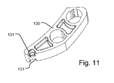
- the reinforcing element 180 is received in a recess 131 in the guide block; the guide block 130 is formed with a corresponding recess in the other side as well, cf. Fig. 11 . This makes it possible to utilize one and the same guide block in the left-hand and the right-hand hinge part.
- the reinforcement element 180 may be provided as a separate element connected to the base plate 101, for instance a rivet, but in a presently preferred embodiment, the reinforcement element 180 is provided as a part formed by the material of the base plate itself as shown in the cross-sectional view of Fig. 10 .
- the deformation of the material to provide the reinforcement element 180 may be provided in any suitable manner, for instance by punching or embossing the base plate 101.
- a reinforcement plate 260 (cf. Fig. 3 ) is connected to the base plate 201 of the sash hinge part 200.
- the base plate 201 of the sash hinge part 200 is in a manner known per se provided with a number of spigots 211 and 212 on its back side to be inserted into corresponding bores in the sash side member. Additional separate fastening means such as screws may be present as well to be introduced through the base plate 201 and connected to the sash side member. Alternatively, only separate fastening means may be utilized. However, all of these fastening means are located within the contours of the base plate 201 itself. In particular, the spigots 211 and 212 are virtually located along the same longitudinal position of the sash side member.
- the pivot hinge in the embodiment shown is provided with additional fastening means displaced from the base plate 201, and the reinforcement plate 260 is thus provided with an aperture 213 adapted to receive supplemental fastening means displaced from the base plate 201 of the sash hinge part 200.
- the supplemental fastening means introduced through the displaced aperture 213 is thus positioned in another grain than the spigots 211 and 212 located within the contour of the base plate.
- the frame hinge part 100 is provided with a spigot 111, and the spigot 111 together with the connection between the frame hinge part 100 and the sledge guidance 16 of the above embodiment transfer the load that the frame hinge part 100 is subjected to, further into the frame structure.
- the sledge guidance 16 and other parts of the lifting device, such as the spring arrangement 13 is as described in the above received in the longitudinally extending recess 10a in the frame side member 1 a and the frame part 11 of the lifting device 10 in the frame part receiving recess 10b. This provides for a satisfying distribution and transfer of the load into the frame structure.
Landscapes
- Engineering & Computer Science (AREA)
- Mechanical Engineering (AREA)
- Architecture (AREA)
- Civil Engineering (AREA)
- Structural Engineering (AREA)
- Hinges (AREA)
Abstract
Description
- The present invention relates to a pivot hinge fitting comprising a frame hinge part having a base plate and a guidance including a guide block, and a sash hinge part having a base plate, the frame hinge part being adapted to be connected to a frame structure and the sash hinge part being adapted to be connected to a sash structure by means of fastening means. The invention furthermore relates to a roof window comprising such a hinge fitting.
- Such pivot hinge fittings are well known in the art, examples being shown in, e.g., international published applications Nos.
WO 85/02646 WO 99/28581 - The pivot hinge fitting is traditionally of a relatively complex design as the structure comprises a large number of metal parts, possibly supplemented by a few parts of a plastic material. As a result, the hinge fitting is able to withstand the forces to which it is exposed in use; however, the costs relating to manufacture and assembly of the hinge fitting are considerable. Furthermore, the hinge fitting should be maintained by lubricating the metal parts occasionally.
- One attempt at reducing the complexity and diminish the need for maintenance is described in
WO 01/31155 - One example of alleviating the above disadvantages is described in Applicant's European patent No.
1 781 833 , which provides for a simple yet reliable design. - In some fields of application, the pivot hinge fitting is subjected to larger than average loads. As the space available at the site of the pivot hinge fitting is limited, and as there is a general desire to optimize the material utilized, the option of merely choosing heavier material is not viable or sound from a manufacturing point of view.
- On this background it is an object of the present invention to provide a pivot hinge fitting which has improved properties as regards the distribution and transfer of loads, but is simple and cost-effective to manufacture and assemble.
- In a first aspect, this object is achieved by a pivot hinge fitting of the kind mentioned in the introduction and which is furthermore characterized in that the pivot hinge fitting includes a plurality of reinforcement elements including at least one reinforcement element adapted to cooperate with the fastening means.
- Thereby a pivot hinge fitting is provided, in which at least some of the load that the pivot hinge fitting is subjected to is distributed and transferred to the structures connected by the pivot hinge fitting via the reinforcement elements connected to the fastening means.
- In a second aspect, a roof window comprising such a pivot hinge fitting is provided.
- Presently preferred embodiments and further advantages will be apparent from the following detailed description and the dependent claims.
- The invention will be described in more detail below by means of a non-limiting example of an embodiment and with reference to the schematic drawing, in which
-
Fig. 1 shows a perspective view of a roof window according to the invention; -
Fig. 2 shows a partial perspective view of an embodiment of a roof window, seen from the inside; -
Fig. 3 shows a partial perspective view of a detail of the roof window of the embodiment shown inFig. 2 ; -
Fig. 4 shows a view corresponding toFig. 3 , with some parts removed; -
Fig. 5 shows a view corresponding toFig. 3 , seen from another angle; -
Fig. 6 shows a view as inFig. 5 , on a larger scale, and from a slightly different angle; -
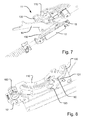
Fig. 7 shows a view corresponding toFig. 5 , with some parts removed; -
Fig. 8 shows a perspective view of other details of an embodiment of the roof window according to the invention; -
Fig. 9 shows a partial view of the details ofFig. 8 , on a larger scale; -
Fig. 10 shows a cross-sectional views of the details ofFig. 9 ; and -
Fig. 11 shows a perspective view of one of the details ofFig. 9 . - In the embodiment of the window shown in
Fig. 1 , the window comprises asash 2 and awindow frame 1. The window is intended to be built into a surface, which is inclined with respect to the horizontal. At a position between the top and centre of the window, there is a hinge connection between theframe 1 and thesash 2 carrying a glazing in the form of apane 3. The hinge connection will be described in further detail below. In a manner known per se, theframe 1 andsash 2 is each formed by four members of which oneframe side member 1a and onesash side member 2a are indicated. Thesash 2 is openable with respect to theframe 1, as thesash 2 may be moved from a closed position, in which e.g. thesash side member 2a is substantially parallel with theframe side member 1a, to an open position, in which thesash side member 2a forms an angle with theframe side member 1 a. During this movement thesash 2 rotates about a hinge axis α situated at the hinge connection. - The hinge connection comprises a set of hinges of a structure substantially as traditionally utilized in pivot windows. Details of such pivot hinges are disclosed in
EP 1 038 083 B1EP 1 781 883 B1frame hinge part 100 having abase plate 101 with aguidance 121, and asash hinge part 200 having abase plate 201 and aslide rail 220. During operation of the pivot hinge fitting, theslide rail 220 of the sash hinge part slides in the guidance of the frame hingepart 100 in a manner known as such. The guide means of theframe hinge part 100 comprise aguide block 130 andguide parts 120 inserted between abase plate 101 and atop plate 110. Thetop plate 110 of theframe hinge part 100 is connected to thebase plate 101 by means of a number of rivets, and furthermore alever spring 125, not described in detail, as this is standard procedure in such pivot hinge fittings. Correspondingly, the other hinge part, i.e. thesash hinge part 200 comprises abase plate 201 on which theslide rail 220 is rotatably connected. - For assisting the movement of the
sash 2 from the closed position to an open position, a lifting device generally designated 10 is mounted between thesash 2 and theframe 1. Referring now toFigs 2 to 8 , thelifting device 10 in the shown embodiment comprises includes asash part 12 and aframe part 11 including aspring arrangement 13 and alifting arm 14 acting between theframe 1 and thesash 2 to provide a spring bias and assist the movement of the sash. As shown, thespring arrangement 13 is received in a longitudinally extendingrecess 10a in theframe side member 1a and theframe part 11 of thelifting device 10 in a frame part receivingrecess 10b. A corresponding lifting device may be provided at each side of the roof window. - In the position shown in
Fig. 1 , the window is in an open position, in which thesash 2 is still influenced by thelifting device 10. As will be described in further detail below, with the present invention it is possible to open the sash further to a further extent, to an opening angle beyond the angle shown inFig. 1 , in which thelifting device 10 does not participate in the opening movement, but is ready for re-engagement with the sash, when the sash reaches substantially the same opening angle. In the embodiment shown, thelifting arm 14 is affected by a spring bias up until the predefined opening angle, the effect of the spring bias being halted at the predefined opening angle, and thelifting arm 14 is provided with open reception means for engagement means on the sash side member. The halting of the spring bias may for instance be provided by the spring assuming its relaxed position, or by providing a stop. As the reception means are open, the engagement means on the sash side member may be received at any time. - Other details of the lifting device, including the
spring arrangement 13 comprises a spring, or two springs, as is described in further detail in Applicant's above-mentioned European patent No.0 733 146 B1 , the contents of which are hereby incorporated by reference. - The operation of the lifting device when installed in the embodiment of the roof window is as follows:
- From a closed position, the user operates the operating device of the window. The operating device may be a handle (not shown) connected with the sash bottom member. The bias of the
lifting device 10 is transmitted to thelifting arm 14. Thelifting arm 14 exerts a moment on thesash 1, and in combination with the force, and hence moment, exerted by the user operating the operating device, the moment resulting from the weight of thesash 1 andpane 3 is overcome. During this movement, thesledge 15 and thelifting arm 14 are displaced along thesledge guidance 16. All in all, this operation entails that thesash 1 is moved from a closed position to an open position as represented byFig. 1 , in which the sash plane forms an opening angle with the frame plane. Closing the window from the open position entails the opposite movements of thesash 1 and relevant parts of the lifting device. It is possible to position thesash 2 in a number of arbitrary opening positions, in which thesash 2 is held stable relative to theframe 1. Up to the predefined opening angle, in which thelifting arm 14 has reached its stable releasing and receiving position, thelifting arm 14 follows the movement of thesash 2. Opening the window further, thesash 2 is moved out of engagement with the liftingarm 2, but may still be positioned in further arbitrary opening positions. - In
Fig. 2 , the liftingdevice 10 assumes substantially the same position as shown inFig. 1 . The liftingarm 14 of thelifting device 10 is at afirst end 141 connected to theframe part 11 and its opposite,other end 142 is releasably connected with thesash 2 via thesash part 12 of thelifting device 10. In the position shown inFig. 2 , the liftingarm 14 assumes a stable releasing and receiving position at a predefined opening angle. In the embodiment shown, this predefined opening angle is approximately 45°. In principle, the predefined opening angle to be defined by the liftingarm 14 may assume any suitable value making it possible to obtain a sufficient opening and at the same time reliable operation of the lifting device. Advantageously, the predefined opening angle defined by the liftingarm 14 lies in the range 20° to 80°, preferably 30° to 60°, more preferably 35° to 50°. Depending on the length of the liftingarm 14 and the dimensions of the hinge connection itself, thesash 2 andwindow frame 1, and the position of the hinge connection, this predefined opening angle has a correlation to the angle formed between a general length direction of the liftingarm 14 and theframe side member 1 a in the stable releasing and receiving position. - In the embodiment shown, the
first end 141 of the liftingarm 14 is rotatably connected to a spring-biasedsledge 15 accommodated in asledge guidance 16 connected to theframe side member 2a, and the opposite,second end 142 includes open reception means, which are here constituted by a fork orcradle 143 adapted to be connected to an engagement means connected to thesash side member 1 a. The engagement means of thesash part 12, which in turn is connected to thesash side member 1a in its mounted position, has the form of arivet 21 connected to asash hinge part 200 of a hinge fitting of said set of hinges. Thesledge guidance 16 is, in the embodiment shown connected to theframe hinge part 100 by means of fastening means such as rivets. As shown, thesledge 15 itself is mounted in arunner 17 fitting slidingly into thesledge guidance 16. The liftingarm 14 is spring-biased towards the stable releasing and receiving position at the predefined opening angle by means of awire spring 150. Thewire spring 150 has the function of keeping the liftingarm 14 in the correct position at all times. To this end, thewire spring 150 may as indicated be mounted with a slight inclination to force the liftingarm 14 in the direction of the sash. In this manner, secure engagement of the liftingarm 14 with therivet 21 is ensured. Furthermore, a holdingclip 160 adapted to accommodate fastening means for a side frame cladding is connected to thebase plate 101 of theframe hinge part 100. - In the embodiment shown, the
rivet 21 constituting the engagement means is connected to thebase plate 201 of thesash hinge part 200. Therivet 21 is formed with such dimensions that it is able to transmit the load properly into thesash hinge part 200 and further into the sash structure itself. In order to reinforce the engagement between therivet 21 and thebase plate 201 of thesash hinge part 200, the rivet is formed with a collar-like structure in that therivet 21 is inserted from the back side of the base plate 201 (cf.Fig. 3 ) and abuts against the back side with afirst collar part 21 a. Following this, asecond collar part 21 b is formed at the front side of thebase plate 201 as shown most clearly inFig. 6 . - As indicated in
Fig. 1 , the hinge axis α is located between a centre axis and the top of the roof window, preferably in theinterval 1/3 to 2/3 of the distance between the centre axis and the top, most preferred substantially at 1/2 of the distance between the centre axis and the top. - A further aspect of the present invention is conceived in response to the recognition that a pivot hinge fitting as described in the above is subjected to a larger load than other hinges. In order to meet the requirements, a number of precautions are foreseen in the embodiments shown and described:
- As shown in for instance
Figs 2 ,4 and6 , thebase plate 101 of theframe hinge part 100 is provided with adistance bushing 170 adapted to abut theframe side member 1 a, viz. in the framepart receiving recess 10b. - In order to make the pivot hinge of the present invention able to withstand larger forces, partly due to the position of the hinge, partly due to its function to transmit the load from the sash to the frame via the lifting arm, a number of measures have been taken to reinforce the pivot hinge and to secure that the load is transmitted safely to the sash and frame structures.
- A first measure will be described with particular reference to
Figs 9 to 11 , in which thebase plate 101 of the frame hinge part comprises a reinforcingelement 180 adapted to support the guide block 130 of theframe hinge part 100. As shown, the reinforcingelement 180 is received in arecess 131 in the guide block; theguide block 130 is formed with a corresponding recess in the other side as well, cf.Fig. 11 . This makes it possible to utilize one and the same guide block in the left-hand and the right-hand hinge part. Thereinforcement element 180 may be provided as a separate element connected to thebase plate 101, for instance a rivet, but in a presently preferred embodiment, thereinforcement element 180 is provided as a part formed by the material of the base plate itself as shown in the cross-sectional view ofFig. 10 . The deformation of the material to provide thereinforcement element 180 may be provided in any suitable manner, for instance by punching or embossing thebase plate 101. - Moreover, a reinforcement plate 260 (cf.
Fig. 3 ) is connected to thebase plate 201 of thesash hinge part 200. Thebase plate 201 of thesash hinge part 200 is in a manner known per se provided with a number ofspigots base plate 201 and connected to the sash side member. Alternatively, only separate fastening means may be utilized. However, all of these fastening means are located within the contours of thebase plate 201 itself. In particular, thespigots sash hinge part 200. However, in some applications, for instance in such windows in which the hinge axis is located at a position between the top and the centre, forces from for instance a sudden impact may cause a local load which in the worst case will lead to splitting of the sash member. This is particularly pronounced in frame and sash structures made of wood, in which the direction of the grains or streak direction is often more or less parallel with the length direction or the frame and sash members. In order to counteract such disadvantageous load distribution, the pivot hinge in the embodiment shown is provided with additional fastening means displaced from thebase plate 201, and thereinforcement plate 260 is thus provided with anaperture 213 adapted to receive supplemental fastening means displaced from thebase plate 201 of thesash hinge part 200. The supplemental fastening means introduced through the displacedaperture 213 is thus positioned in another grain than thespigots - Also the
frame hinge part 100 is provided with aspigot 111, and thespigot 111 together with the connection between theframe hinge part 100 and thesledge guidance 16 of the above embodiment transfer the load that theframe hinge part 100 is subjected to, further into the frame structure. Thesledge guidance 16 and other parts of the lifting device, such as thespring arrangement 13 is as described in the above received in thelongitudinally extending recess 10a in theframe side member 1 a and theframe part 11 of thelifting device 10 in the framepart receiving recess 10b. This provides for a satisfying distribution and transfer of the load into the frame structure. - Further embodiments include the following itemized list:
- A. A roof window, wherein the predefined opening angle defined by the lifting arm lies in the range 20° to 80°, preferably 30° to 60°, more preferably 35° to 50°.
- B. A roof window, wherein the hinge axis (α) is located between a centre axis and the top of the roof window, preferably in the
interval 1/3 to 2/3 of the distance between the centre axis and the top, most preferred substantially at 1/2 of the distance between the centre axis and the top. - It should be noted that the above description of presently preferred embodiments serves only as an example, and that a person skilled in the art will know that numerous variations are possible without deviating from the scope of the claims.
Claims (15)
- A pivot hinge fitting comprising a frame hinge part (100) having a base plate (101) and a guidance including a guide block (130), and a sash hinge part (200) having a base plate (201), the frame hinge part (100) being adapted to be connected to a frame structure and the sash hinge part (200) being adapted to be connected to a sash structure by means of fastening means, characterized in that the pivot hinge fitting includes a plurality of reinforcement elements including at least one reinforcement element adapted to cooperate with the fastening means.
- A pivot hinge fitting according to claim 1, wherein a reinforcement element in the form of a reinforcement plate (260) is connected to the base plate (201) of the sash hinge part (200), the reinforcement plate (260) being provided with an aperture adapted to receive supplemental fastening means displaced from the base plate (201) of the sash hinge part (200).
- A pivot hinge fitting according to any one of claims 1 and 2, wherein the base plate (101) of the frame hinge part (100) comprises a reinforcing element (180) adapted to support the guide block (130) of the frame hinge part (100).
- A pivot hinge fitting according to claim 3, wherein the reinforcement element (180) is formed as a part formed by the material of the base plate itself.
- A pivot hinge fitting according to any one of claims 3 and 4, wherein the guide block (130) is provided with a recess (131) adapted to receive the reinforcing element (180).
- A pivot hinge fitting according to claim 5, wherein the guide block (130) is formed with a corresponding recess in the other side as well.
- A roof window comprising:a frame (1) having a top member, a bottom member and two side members (1 a) defining a frame plane,a sash (2) having a top member, a bottom member and two side members (2a), said sash carrying a pane (3) and defining a sash plane, the sash being connected with the frame by means of a set of hinges (100, 200) defining a hinge axis of the window,characterized in that said each set of hinges comprises a pivot hinge fitting (100, 200) including a plurality of reinforcement elements including at least one reinforcement element adapted to cooperate with the fastening means.
- A roof window according to claim 7, wherein the roof window further comprises a lifting device (10) including a lifting arm (14) adapted to act between the frame and the sash to provide a spring bias and assist the movement of the sash, and wherein the lifting arm (14) of the lifting device (10) is releasably connected with the sash (2), and that the lifting arm is adapted to assume a stable releasing and receiving position at a predefined opening angle.
- A roof window according to claim 8, wherein the lifting arm (14) is affected by a spring bias up until the predefined opening angle, the effect of the spring bias being halted at the predefined opening angle, and the lifting arm (14) being provided with open reception means for engagement means (21) on the sash side member.
- A roof window according to claim 9, wherein the spring bias is provided in that the lifting arm (14) has a first end (141) rotatably connected to a spring-biased sledge (15) connected to a frame side member (1 a) and an opposite, second end (142) including a fork or cradle (143) adapted to be connected to the engagement means (21) connected to the sash side member.
- A roof window according to claim 10, wherein the engagement means has the form of a rivet (21) connected to the sash hinge part (200) of the pivot hinge fitting, preferably to the base plate (201) of the sash hinge part (200).
- A roof window according to claim 10 or 11, wherein the sledge (15) is accommodated in a sledge guidance (16) connected to the frame hinge part (100) of a hinge fitting of said set of hinges, preferably in a runner (17).
- A roof window according to any one of claims 10 to 13, wherein the lifting arm (14) is spring-biased towards the stable releasing and receiving position at the predefined opening angle by means of a wire spring (150).
- A roof window according to any one of claims 7 to 13, wherein the base plate (101) of the frame hinge part (100) is provided with a distance bushing (170) adapted to abut the frame side member (1 a).
- A roof window according to any one of claims 7 to 14, wherein a lifting device (10) is provided at each side of the roof window.
Priority Applications (1)
| Application Number | Priority Date | Filing Date | Title |
|---|---|---|---|
| PL13199396T PL2770146T3 (en) | 2013-02-22 | 2013-12-23 | An improved pivot hinge fitting and a roof window comprising such a hinge fitting |
Applications Claiming Priority (1)
| Application Number | Priority Date | Filing Date | Title |
|---|---|---|---|
| DK201370100A DK178257B1 (en) | 2013-02-22 | 2013-02-22 | A pivot hinge fitting and a roof window comprising such a hinge fitting |
Publications (2)
| Publication Number | Publication Date |
|---|---|
| EP2770146A1 true EP2770146A1 (en) | 2014-08-27 |
| EP2770146B1 EP2770146B1 (en) | 2018-02-14 |
Family
ID=49841595
Family Applications (1)
| Application Number | Title | Priority Date | Filing Date |
|---|---|---|---|
| EP13199396.6A Active EP2770146B1 (en) | 2013-02-22 | 2013-12-23 | An improved pivot hinge fitting and a roof window comprising such a hinge fitting |
Country Status (3)
| Country | Link |
|---|---|
| EP (1) | EP2770146B1 (en) |
| DK (1) | DK178257B1 (en) |
| PL (1) | PL2770146T3 (en) |
Cited By (11)
| Publication number | Priority date | Publication date | Assignee | Title |
|---|---|---|---|---|
| WO2017076416A1 (en) | 2015-11-06 | 2017-05-11 | Vkr Holding A/S | A hinge for a roof window, and a roof window including a set of hinges |
| EP3299536A1 (en) | 2016-09-23 | 2018-03-28 | VKR Holding A/S | A roof window including a set of hinges with improved movement pattern |
| DE202017106969U1 (en) | 2016-11-18 | 2018-04-13 | Vkr Holding A/S | A hinge assembly with a braking device and a biasing device, and a roof window with such a hinge assembly |
| WO2018202915A1 (en) | 2017-05-05 | 2018-11-08 | Vkr Holding A/S | A hinge for a window, a window including a set of such hinges, and a method of installing such a window |
| EP3730716A1 (en) | 2018-04-30 | 2020-10-28 | VKR Holding A/S | Roof window with improved covering arrangement and method of providing a roof window with improved covering arrangement |
| EP3828359A1 (en) | 2019-11-29 | 2021-06-02 | VKR Holding A/S | A roof window arrangement comprising a plurality of sash structures and a common frame, and including a covering assembly, and method of manufacturing such a roof window arrangement |
| WO2022228633A1 (en) | 2021-04-29 | 2022-11-03 | Vkr Holding A/S | Hinge for a roof window and roof window with a set of hinges |
| WO2022228634A1 (en) | 2021-04-29 | 2022-11-03 | Vkr Holding A/S | Hinge for a roof window and roof window with a set of hinges |
| WO2022228635A1 (en) | 2021-04-29 | 2022-11-03 | Vkr Holding A/S | Roof window with a set of hinges |
| WO2022228632A1 (en) | 2021-04-29 | 2022-11-03 | Vkr Holding A/S | Hinge for a roof window and roof window with a set of hinges |
| EP4257772A1 (en) | 2022-03-31 | 2023-10-11 | VKR Holding A/S | A roof window arrangement comprising a plurality of window units and a common frame, and method of installing such a roof window arrangement |
Families Citing this family (1)
| Publication number | Priority date | Publication date | Assignee | Title |
|---|---|---|---|---|
| DK182237B1 (en) | 2023-08-21 | 2025-12-19 | Vkr Holding As | A roof window arrangement comprising a common stationary frame and at least a first window unit and a second window unit |
Citations (4)
| Publication number | Priority date | Publication date | Assignee | Title |
|---|---|---|---|---|
| US4055024A (en) * | 1975-05-03 | 1977-10-25 | Wilh. Frank Gmbh | Roof window arrangement |
| EP1781883A1 (en) * | 2004-07-02 | 2007-05-09 | VKR Holding A/S | Hinge fitting having an intermediate member, window comprising such hinge fittings and use of such a hinge fitting |
| WO2010005330A2 (en) * | 2008-07-11 | 2010-01-14 | Fakro Pp Spolka Z O. O. | Wooden window frame, especially for roof window |
| WO2010005331A1 (en) * | 2008-07-11 | 2010-01-14 | Fakro Pp Spolka Z O. O. | Hinge of a roof window pivot sash and a unit for fastening the hinge to the frame, in particular of a roof window sash |
Family Cites Families (1)
| Publication number | Priority date | Publication date | Assignee | Title |
|---|---|---|---|---|
| PL215150B1 (en) * | 2006-07-24 | 2013-10-31 | Fakro Pp Spolka Z Ograniczona Odpowiedzialnoscia | Hinge for pivoting roof light and method for mounting the hinge in pivoting roof light, particularly with frame made of multi-chamber plastic sections |
-
2013
- 2013-02-22 DK DK201370100A patent/DK178257B1/en active
- 2013-12-23 EP EP13199396.6A patent/EP2770146B1/en active Active
- 2013-12-23 PL PL13199396T patent/PL2770146T3/en unknown
Patent Citations (4)
| Publication number | Priority date | Publication date | Assignee | Title |
|---|---|---|---|---|
| US4055024A (en) * | 1975-05-03 | 1977-10-25 | Wilh. Frank Gmbh | Roof window arrangement |
| EP1781883A1 (en) * | 2004-07-02 | 2007-05-09 | VKR Holding A/S | Hinge fitting having an intermediate member, window comprising such hinge fittings and use of such a hinge fitting |
| WO2010005330A2 (en) * | 2008-07-11 | 2010-01-14 | Fakro Pp Spolka Z O. O. | Wooden window frame, especially for roof window |
| WO2010005331A1 (en) * | 2008-07-11 | 2010-01-14 | Fakro Pp Spolka Z O. O. | Hinge of a roof window pivot sash and a unit for fastening the hinge to the frame, in particular of a roof window sash |
Cited By (24)
| Publication number | Priority date | Publication date | Assignee | Title |
|---|---|---|---|---|
| EP3702564A1 (en) | 2015-11-06 | 2020-09-02 | VKR Holding A/S | A hinge for a roof window, and a roof window including a set of hinges |
| WO2017076416A1 (en) | 2015-11-06 | 2017-05-11 | Vkr Holding A/S | A hinge for a roof window, and a roof window including a set of hinges |
| EP3702563A1 (en) | 2015-11-06 | 2020-09-02 | VKR Holding A/S | A hinge for a roof window, and a roof window including a set of hinges |
| EP3299536B1 (en) * | 2016-09-23 | 2019-12-11 | VKR Holding A/S | A roof window including a set of hinges with improved movement pattern |
| DK201670757A1 (en) * | 2016-09-23 | 2018-04-16 | Vkr Holding As | A roof window including a set of hinges with improved movement pattern |
| EP3299536A1 (en) | 2016-09-23 | 2018-03-28 | VKR Holding A/S | A roof window including a set of hinges with improved movement pattern |
| DE202017106974U1 (en) | 2016-11-18 | 2018-04-13 | Vkr Holding A/S | A hinge assembly with a transfer device and a biasing device, and a roof window with such a hinge assembly |
| DE202017106972U1 (en) | 2016-11-18 | 2018-04-13 | Vkr Holding A/S | A hinge assembly with a track and a biasing device, and a roof window with such a hinge assembly |
| EP3323968A1 (en) | 2016-11-18 | 2018-05-23 | VKR Holding A/S | A hinge arrangement of a roof window with improved operability |
| DE202017106967U1 (en) | 2016-11-18 | 2018-04-13 | Vkr Holding A/S | A hinge assembly with arcuate guide means and a braking device, and a roof window with such a hinge assembly |
| DE202017106969U1 (en) | 2016-11-18 | 2018-04-13 | Vkr Holding A/S | A hinge assembly with a braking device and a biasing device, and a roof window with such a hinge assembly |
| EP3842610A1 (en) | 2016-11-18 | 2021-06-30 | VKR Holding A/S | A hinge arrangement of a roof window with improved operability |
| WO2018202915A1 (en) | 2017-05-05 | 2018-11-08 | Vkr Holding A/S | A hinge for a window, a window including a set of such hinges, and a method of installing such a window |
| US11028627B2 (en) | 2017-05-05 | 2021-06-08 | Vkr Holding A/S | Hinge for a window, a window including a set of such hinges, and a method of installing such a window |
| EP3730716A1 (en) | 2018-04-30 | 2020-10-28 | VKR Holding A/S | Roof window with improved covering arrangement and method of providing a roof window with improved covering arrangement |
| EP3828359A1 (en) | 2019-11-29 | 2021-06-02 | VKR Holding A/S | A roof window arrangement comprising a plurality of sash structures and a common frame, and including a covering assembly, and method of manufacturing such a roof window arrangement |
| WO2022228633A1 (en) | 2021-04-29 | 2022-11-03 | Vkr Holding A/S | Hinge for a roof window and roof window with a set of hinges |
| WO2022228634A1 (en) | 2021-04-29 | 2022-11-03 | Vkr Holding A/S | Hinge for a roof window and roof window with a set of hinges |
| WO2022228635A1 (en) | 2021-04-29 | 2022-11-03 | Vkr Holding A/S | Roof window with a set of hinges |
| WO2022228632A1 (en) | 2021-04-29 | 2022-11-03 | Vkr Holding A/S | Hinge for a roof window and roof window with a set of hinges |
| EP4365398A2 (en) | 2021-04-29 | 2024-05-08 | VKR Holding A/S | Hinge for a roof window and roof window with a set of hinges |
| EP4365396A2 (en) | 2021-04-29 | 2024-05-08 | VKR Holding A/S | Hinge for a roof window and roof window with a set of hinges |
| US12173504B2 (en) | 2021-04-29 | 2024-12-24 | Vkr Holding A/S | Roof window with a set of hinges |
| EP4257772A1 (en) | 2022-03-31 | 2023-10-11 | VKR Holding A/S | A roof window arrangement comprising a plurality of window units and a common frame, and method of installing such a roof window arrangement |
Also Published As
| Publication number | Publication date |
|---|---|
| EP2770146B1 (en) | 2018-02-14 |
| DK201370100A (en) | 2014-08-23 |
| PL2770146T3 (en) | 2018-07-31 |
| DK178257B1 (en) | 2015-10-12 |
Similar Documents
| Publication | Publication Date | Title |
|---|---|---|
| EP2770146B1 (en) | An improved pivot hinge fitting and a roof window comprising such a hinge fitting | |
| EP2770149B1 (en) | A roof window having a lifting device and hinge connection | |
| US6438795B1 (en) | Buffer device | |
| EP3332078B1 (en) | Hinge device with long reciprocating stroke of a front panel | |
| EP2762665B1 (en) | A pivot hinge fitting with engagement means and a roof window comprising a set of such pivot hinge fittings | |
| EP2295692B1 (en) | Door or wing for electrical household appliances | |
| JP7650324B2 (en) | Window stays | |
| JP2009543724A (en) | Integrated hinge assembly with spring bias prop arm | |
| KR102010377B1 (en) | Stay bar unit of turning type window system | |
| CN105201314A (en) | Multifunctional hidden hinge convenient for window cleaning | |
| PH12014000082A1 (en) | Hatch cover apparatus for vessel | |
| EP2339103A2 (en) | Hinge for pivot windows | |
| EP3027833A1 (en) | Improved guide device for the opening and the support of doors of furniture | |
| US8276317B2 (en) | Auto locking, manual unlocking door stay | |
| EP2281984A1 (en) | A lock assembly | |
| CN107060542A (en) | A kind of sliding block and slide support hinge of window slide support hinge | |
| FR2951489A1 (en) | Toilet door actuating mechanism for e.g. enterprise, has carrier transmitting efforts of pressure of foot on levers towards articulated actuating arms fixed above door, where arms open and close door | |
| JP2007308888A (en) | Hinged door shock absorber | |
| CN205344896U (en) | EMUs are pulled with light -duty parlor | |
| KR101654051B1 (en) | Apartment Door Sag Prevention Device | |
| EP1899563A2 (en) | Sash hinge | |
| EP2000612B1 (en) | Scaffold with lockable legs | |
| KR20210047050A (en) | Slide type open-door in household | |
| US9353538B1 (en) | Stiffening strut for garage door panels | |
| CN211851366U (en) | Hidden hinge capable of increasing bearing capacity |
Legal Events
| Date | Code | Title | Description |
|---|---|---|---|
| PUAI | Public reference made under article 153(3) epc to a published international application that has entered the european phase |
Free format text: ORIGINAL CODE: 0009012 |
|
| 17P | Request for examination filed |
Effective date: 20131223 |
|
| AK | Designated contracting states |
Kind code of ref document: A1 Designated state(s): AL AT BE BG CH CY CZ DE DK EE ES FI FR GB GR HR HU IE IS IT LI LT LU LV MC MK MT NL NO PL PT RO RS SE SI SK SM TR |
|
| AX | Request for extension of the european patent |
Extension state: BA ME |
|
| R17P | Request for examination filed (corrected) |
Effective date: 20150227 |
|
| RBV | Designated contracting states (corrected) |
Designated state(s): AL AT BE BG CH CY CZ DE DK EE ES FI FR GB GR HR HU IE IS IT LI LT LU LV MC MK MT NL NO PL PT RO RS SE SI SK SM TR |
|
| 17Q | First examination report despatched |
Effective date: 20160530 |
|
| GRAP | Despatch of communication of intention to grant a patent |
Free format text: ORIGINAL CODE: EPIDOSNIGR1 |
|
| INTG | Intention to grant announced |
Effective date: 20170908 |
|
| RIN1 | Information on inventor provided before grant (corrected) |
Inventor name: HOLM, MICHAEL GALSGARD Inventor name: HEDE, LASSE VINTHER Inventor name: VESTERBY, LASSE |
|
| GRAS | Grant fee paid |
Free format text: ORIGINAL CODE: EPIDOSNIGR3 |
|
| GRAA | (expected) grant |
Free format text: ORIGINAL CODE: 0009210 |
|
| AK | Designated contracting states |
Kind code of ref document: B1 Designated state(s): AL AT BE BG CH CY CZ DE DK EE ES FI FR GB GR HR HU IE IS IT LI LT LU LV MC MK MT NL NO PL PT RO RS SE SI SK SM TR |
|
| REG | Reference to a national code |
Ref country code: GB Ref legal event code: FG4D |
|
| REG | Reference to a national code |
Ref country code: CH Ref legal event code: EP |
|
| REG | Reference to a national code |
Ref country code: IE Ref legal event code: FG4D |
|
| REG | Reference to a national code |
Ref country code: DE Ref legal event code: R096 Ref document number: 602013033063 Country of ref document: DE Ref country code: AT Ref legal event code: REF Ref document number: 969936 Country of ref document: AT Kind code of ref document: T Effective date: 20180315 |
|
| REG | Reference to a national code |
Ref country code: NL Ref legal event code: MP Effective date: 20180214 |
|
| REG | Reference to a national code |
Ref country code: AT Ref legal event code: MK05 Ref document number: 969936 Country of ref document: AT Kind code of ref document: T Effective date: 20180214 |
|
| PG25 | Lapsed in a contracting state [announced via postgrant information from national office to epo] |
Ref country code: NO Free format text: LAPSE BECAUSE OF FAILURE TO SUBMIT A TRANSLATION OF THE DESCRIPTION OR TO PAY THE FEE WITHIN THE PRESCRIBED TIME-LIMIT Effective date: 20180514 Ref country code: HR Free format text: LAPSE BECAUSE OF FAILURE TO SUBMIT A TRANSLATION OF THE DESCRIPTION OR TO PAY THE FEE WITHIN THE PRESCRIBED TIME-LIMIT Effective date: 20180214 Ref country code: CY Free format text: LAPSE BECAUSE OF FAILURE TO SUBMIT A TRANSLATION OF THE DESCRIPTION OR TO PAY THE FEE WITHIN THE PRESCRIBED TIME-LIMIT Effective date: 20180214 Ref country code: NL Free format text: LAPSE BECAUSE OF FAILURE TO SUBMIT A TRANSLATION OF THE DESCRIPTION OR TO PAY THE FEE WITHIN THE PRESCRIBED TIME-LIMIT Effective date: 20180214 Ref country code: LT Free format text: LAPSE BECAUSE OF FAILURE TO SUBMIT A TRANSLATION OF THE DESCRIPTION OR TO PAY THE FEE WITHIN THE PRESCRIBED TIME-LIMIT Effective date: 20180214 Ref country code: ES Free format text: LAPSE BECAUSE OF FAILURE TO SUBMIT A TRANSLATION OF THE DESCRIPTION OR TO PAY THE FEE WITHIN THE PRESCRIBED TIME-LIMIT Effective date: 20180214 Ref country code: FI Free format text: LAPSE BECAUSE OF FAILURE TO SUBMIT A TRANSLATION OF THE DESCRIPTION OR TO PAY THE FEE WITHIN THE PRESCRIBED TIME-LIMIT Effective date: 20180214 |
|
| PG25 | Lapsed in a contracting state [announced via postgrant information from national office to epo] |
Ref country code: RS Free format text: LAPSE BECAUSE OF FAILURE TO SUBMIT A TRANSLATION OF THE DESCRIPTION OR TO PAY THE FEE WITHIN THE PRESCRIBED TIME-LIMIT Effective date: 20180214 Ref country code: AT Free format text: LAPSE BECAUSE OF FAILURE TO SUBMIT A TRANSLATION OF THE DESCRIPTION OR TO PAY THE FEE WITHIN THE PRESCRIBED TIME-LIMIT Effective date: 20180214 Ref country code: LV Free format text: LAPSE BECAUSE OF FAILURE TO SUBMIT A TRANSLATION OF THE DESCRIPTION OR TO PAY THE FEE WITHIN THE PRESCRIBED TIME-LIMIT Effective date: 20180214 Ref country code: SE Free format text: LAPSE BECAUSE OF FAILURE TO SUBMIT A TRANSLATION OF THE DESCRIPTION OR TO PAY THE FEE WITHIN THE PRESCRIBED TIME-LIMIT Effective date: 20180214 Ref country code: GR Free format text: LAPSE BECAUSE OF FAILURE TO SUBMIT A TRANSLATION OF THE DESCRIPTION OR TO PAY THE FEE WITHIN THE PRESCRIBED TIME-LIMIT Effective date: 20180515 Ref country code: BG Free format text: LAPSE BECAUSE OF FAILURE TO SUBMIT A TRANSLATION OF THE DESCRIPTION OR TO PAY THE FEE WITHIN THE PRESCRIBED TIME-LIMIT Effective date: 20180514 |
|
| PG25 | Lapsed in a contracting state [announced via postgrant information from national office to epo] |
Ref country code: AL Free format text: LAPSE BECAUSE OF FAILURE TO SUBMIT A TRANSLATION OF THE DESCRIPTION OR TO PAY THE FEE WITHIN THE PRESCRIBED TIME-LIMIT Effective date: 20180214 Ref country code: IT Free format text: LAPSE BECAUSE OF FAILURE TO SUBMIT A TRANSLATION OF THE DESCRIPTION OR TO PAY THE FEE WITHIN THE PRESCRIBED TIME-LIMIT Effective date: 20180214 Ref country code: EE Free format text: LAPSE BECAUSE OF FAILURE TO SUBMIT A TRANSLATION OF THE DESCRIPTION OR TO PAY THE FEE WITHIN THE PRESCRIBED TIME-LIMIT Effective date: 20180214 Ref country code: RO Free format text: LAPSE BECAUSE OF FAILURE TO SUBMIT A TRANSLATION OF THE DESCRIPTION OR TO PAY THE FEE WITHIN THE PRESCRIBED TIME-LIMIT Effective date: 20180214 |
|
| REG | Reference to a national code |
Ref country code: DE Ref legal event code: R097 Ref document number: 602013033063 Country of ref document: DE |
|
| PG25 | Lapsed in a contracting state [announced via postgrant information from national office to epo] |
Ref country code: SM Free format text: LAPSE BECAUSE OF FAILURE TO SUBMIT A TRANSLATION OF THE DESCRIPTION OR TO PAY THE FEE WITHIN THE PRESCRIBED TIME-LIMIT Effective date: 20180214 Ref country code: CZ Free format text: LAPSE BECAUSE OF FAILURE TO SUBMIT A TRANSLATION OF THE DESCRIPTION OR TO PAY THE FEE WITHIN THE PRESCRIBED TIME-LIMIT Effective date: 20180214 Ref country code: DK Free format text: LAPSE BECAUSE OF FAILURE TO SUBMIT A TRANSLATION OF THE DESCRIPTION OR TO PAY THE FEE WITHIN THE PRESCRIBED TIME-LIMIT Effective date: 20180214 Ref country code: SK Free format text: LAPSE BECAUSE OF FAILURE TO SUBMIT A TRANSLATION OF THE DESCRIPTION OR TO PAY THE FEE WITHIN THE PRESCRIBED TIME-LIMIT Effective date: 20180214 |
|
| PLBE | No opposition filed within time limit |
Free format text: ORIGINAL CODE: 0009261 |
|
| STAA | Information on the status of an ep patent application or granted ep patent |
Free format text: STATUS: NO OPPOSITION FILED WITHIN TIME LIMIT |
|
| 26N | No opposition filed |
Effective date: 20181115 |
|
| PG25 | Lapsed in a contracting state [announced via postgrant information from national office to epo] |
Ref country code: SI Free format text: LAPSE BECAUSE OF FAILURE TO SUBMIT A TRANSLATION OF THE DESCRIPTION OR TO PAY THE FEE WITHIN THE PRESCRIBED TIME-LIMIT Effective date: 20180214 |
|
| REG | Reference to a national code |
Ref country code: CH Ref legal event code: PL |
|
| PG25 | Lapsed in a contracting state [announced via postgrant information from national office to epo] |
Ref country code: MC Free format text: LAPSE BECAUSE OF FAILURE TO SUBMIT A TRANSLATION OF THE DESCRIPTION OR TO PAY THE FEE WITHIN THE PRESCRIBED TIME-LIMIT Effective date: 20180214 Ref country code: LU Free format text: LAPSE BECAUSE OF NON-PAYMENT OF DUE FEES Effective date: 20181223 |
|
| REG | Reference to a national code |
Ref country code: IE Ref legal event code: MM4A |
|
| REG | Reference to a national code |
Ref country code: BE Ref legal event code: MM Effective date: 20181231 |
|
| PG25 | Lapsed in a contracting state [announced via postgrant information from national office to epo] |
Ref country code: IE Free format text: LAPSE BECAUSE OF NON-PAYMENT OF DUE FEES Effective date: 20181223 |
|
| PG25 | Lapsed in a contracting state [announced via postgrant information from national office to epo] |
Ref country code: BE Free format text: LAPSE BECAUSE OF NON-PAYMENT OF DUE FEES Effective date: 20181231 |
|
| PG25 | Lapsed in a contracting state [announced via postgrant information from national office to epo] |
Ref country code: CH Free format text: LAPSE BECAUSE OF NON-PAYMENT OF DUE FEES Effective date: 20181231 Ref country code: LI Free format text: LAPSE BECAUSE OF NON-PAYMENT OF DUE FEES Effective date: 20181231 |
|
| PG25 | Lapsed in a contracting state [announced via postgrant information from national office to epo] |
Ref country code: MT Free format text: LAPSE BECAUSE OF NON-PAYMENT OF DUE FEES Effective date: 20181223 |
|
| PG25 | Lapsed in a contracting state [announced via postgrant information from national office to epo] |
Ref country code: TR Free format text: LAPSE BECAUSE OF FAILURE TO SUBMIT A TRANSLATION OF THE DESCRIPTION OR TO PAY THE FEE WITHIN THE PRESCRIBED TIME-LIMIT Effective date: 20180214 |
|
| PG25 | Lapsed in a contracting state [announced via postgrant information from national office to epo] |
Ref country code: PT Free format text: LAPSE BECAUSE OF FAILURE TO SUBMIT A TRANSLATION OF THE DESCRIPTION OR TO PAY THE FEE WITHIN THE PRESCRIBED TIME-LIMIT Effective date: 20180214 |
|
| PG25 | Lapsed in a contracting state [announced via postgrant information from national office to epo] |
Ref country code: HU Free format text: LAPSE BECAUSE OF FAILURE TO SUBMIT A TRANSLATION OF THE DESCRIPTION OR TO PAY THE FEE WITHIN THE PRESCRIBED TIME-LIMIT; INVALID AB INITIO Effective date: 20131223 Ref country code: MK Free format text: LAPSE BECAUSE OF NON-PAYMENT OF DUE FEES Effective date: 20180214 |
|
| PG25 | Lapsed in a contracting state [announced via postgrant information from national office to epo] |
Ref country code: IS Free format text: LAPSE BECAUSE OF FAILURE TO SUBMIT A TRANSLATION OF THE DESCRIPTION OR TO PAY THE FEE WITHIN THE PRESCRIBED TIME-LIMIT Effective date: 20180614 |
|
| PGFP | Annual fee paid to national office [announced via postgrant information from national office to epo] |
Ref country code: GB Payment date: 20241104 Year of fee payment: 12 |
|
| PGFP | Annual fee paid to national office [announced via postgrant information from national office to epo] |
Ref country code: FR Payment date: 20241121 Year of fee payment: 12 |
|
| PGFP | Annual fee paid to national office [announced via postgrant information from national office to epo] |
Ref country code: DE Payment date: 20251104 Year of fee payment: 13 |
|
| PGFP | Annual fee paid to national office [announced via postgrant information from national office to epo] |
Ref country code: PL Payment date: 20251117 Year of fee payment: 13 |