EP2770146A1 - Ferrure d'articulation de pivotement amélioré et fenêtre de toit comprenant une telle ferrure - Google Patents
Ferrure d'articulation de pivotement amélioré et fenêtre de toit comprenant une telle ferrure Download PDFInfo
- Publication number
- EP2770146A1 EP2770146A1 EP13199396.6A EP13199396A EP2770146A1 EP 2770146 A1 EP2770146 A1 EP 2770146A1 EP 13199396 A EP13199396 A EP 13199396A EP 2770146 A1 EP2770146 A1 EP 2770146A1
- Authority
- EP
- European Patent Office
- Prior art keywords
- sash
- frame
- hinge part
- base plate
- roof window
- Prior art date
- Legal status (The legal status is an assumption and is not a legal conclusion. Google has not performed a legal analysis and makes no representation as to the accuracy of the status listed.)
- Granted
Links
- 230000002787 reinforcement Effects 0.000 claims abstract description 21
- 230000000153 supplemental effect Effects 0.000 claims abstract description 4
- 239000000463 material Substances 0.000 claims description 8
- 230000003014 reinforcing effect Effects 0.000 claims description 4
- 230000000694 effects Effects 0.000 claims description 2
- 238000009826 distribution Methods 0.000 description 3
- 238000004519 manufacturing process Methods 0.000 description 3
- 238000012546 transfer Methods 0.000 description 3
- 238000013461 design Methods 0.000 description 2
- 239000002184 metal Substances 0.000 description 2
- 239000004033 plastic Substances 0.000 description 2
- 229920003023 plastic Polymers 0.000 description 2
- 230000006978 adaptation Effects 0.000 description 1
- 238000005253 cladding Methods 0.000 description 1
- 230000001419 dependent effect Effects 0.000 description 1
- 238000004049 embossing Methods 0.000 description 1
- 230000001050 lubricating effect Effects 0.000 description 1
- 238000012423 maintenance Methods 0.000 description 1
- 238000004080 punching Methods 0.000 description 1
- 238000010561 standard procedure Methods 0.000 description 1
- 239000002023 wood Substances 0.000 description 1
Images


Classifications
-
- E—FIXED CONSTRUCTIONS
- E05—LOCKS; KEYS; WINDOW OR DOOR FITTINGS; SAFES
- E05D—HINGES OR SUSPENSION DEVICES FOR DOORS, WINDOWS OR WINGS
- E05D1/00—Pinless hinges; Substitutes for hinges
- E05D1/04—Pinless hinges; Substitutes for hinges with guide members shaped as circular arcs
-
- E—FIXED CONSTRUCTIONS
- E04—BUILDING
- E04D—ROOF COVERINGS; SKY-LIGHTS; GUTTERS; ROOF-WORKING TOOLS
- E04D13/00—Special arrangements or devices in connection with roof coverings; Protection against birds; Roof drainage ; Sky-lights
- E04D13/03—Sky-lights; Domes; Ventilating sky-lights
- E04D13/035—Sky-lights; Domes; Ventilating sky-lights characterised by having movable parts
- E04D13/0351—Sky-lights; Domes; Ventilating sky-lights characterised by having movable parts the parts pivoting about a fixed axis
- E04D13/0354—Sky-lights; Domes; Ventilating sky-lights characterised by having movable parts the parts pivoting about a fixed axis the parts being flat
-
- E—FIXED CONSTRUCTIONS
- E05—LOCKS; KEYS; WINDOW OR DOOR FITTINGS; SAFES
- E05D—HINGES OR SUSPENSION DEVICES FOR DOORS, WINDOWS OR WINGS
- E05D5/00—Construction of single parts, e.g. the parts for attachment
- E05D5/02—Parts for attachment, e.g. flaps
- E05D5/04—Flat flaps
-
- E—FIXED CONSTRUCTIONS
- E05—LOCKS; KEYS; WINDOW OR DOOR FITTINGS; SAFES
- E05D—HINGES OR SUSPENSION DEVICES FOR DOORS, WINDOWS OR WINGS
- E05D7/00—Hinges or pivots of special construction
- E05D7/08—Hinges or pivots of special construction for use in suspensions comprising two spigots placed at opposite edges of the wing, especially at the top and the bottom, e.g. trunnions
- E05D7/082—Hinges or pivots of special construction for use in suspensions comprising two spigots placed at opposite edges of the wing, especially at the top and the bottom, e.g. trunnions the pivot axis of the wing being situated at a considerable distance from the edges of the wing, e.g. for balanced wings
- E05D7/084—Hinges or pivots of special construction for use in suspensions comprising two spigots placed at opposite edges of the wing, especially at the top and the bottom, e.g. trunnions the pivot axis of the wing being situated at a considerable distance from the edges of the wing, e.g. for balanced wings with a movable pivot axis
-
- E—FIXED CONSTRUCTIONS
- E05—LOCKS; KEYS; WINDOW OR DOOR FITTINGS; SAFES
- E05Y—INDEXING SCHEME ASSOCIATED WITH SUBCLASSES E05D AND E05F, RELATING TO CONSTRUCTION ELEMENTS, ELECTRIC CONTROL, POWER SUPPLY, POWER SIGNAL OR TRANSMISSION, USER INTERFACES, MOUNTING OR COUPLING, DETAILS, ACCESSORIES, AUXILIARY OPERATIONS NOT OTHERWISE PROVIDED FOR, APPLICATION THEREOF
- E05Y2600/00—Mounting or coupling arrangements for elements provided for in this subclass
- E05Y2600/60—Mounting or coupling members; Accessories therefor
- E05Y2600/626—Plates or brackets
-
- E—FIXED CONSTRUCTIONS
- E05—LOCKS; KEYS; WINDOW OR DOOR FITTINGS; SAFES
- E05Y—INDEXING SCHEME ASSOCIATED WITH SUBCLASSES E05D AND E05F, RELATING TO CONSTRUCTION ELEMENTS, ELECTRIC CONTROL, POWER SUPPLY, POWER SIGNAL OR TRANSMISSION, USER INTERFACES, MOUNTING OR COUPLING, DETAILS, ACCESSORIES, AUXILIARY OPERATIONS NOT OTHERWISE PROVIDED FOR, APPLICATION THEREOF
- E05Y2800/00—Details, accessories and auxiliary operations not otherwise provided for
-
- E—FIXED CONSTRUCTIONS
- E05—LOCKS; KEYS; WINDOW OR DOOR FITTINGS; SAFES
- E05Y—INDEXING SCHEME ASSOCIATED WITH SUBCLASSES E05D AND E05F, RELATING TO CONSTRUCTION ELEMENTS, ELECTRIC CONTROL, POWER SUPPLY, POWER SIGNAL OR TRANSMISSION, USER INTERFACES, MOUNTING OR COUPLING, DETAILS, ACCESSORIES, AUXILIARY OPERATIONS NOT OTHERWISE PROVIDED FOR, APPLICATION THEREOF
- E05Y2900/00—Application of doors, windows, wings or fittings thereof
- E05Y2900/10—Application of doors, windows, wings or fittings thereof for buildings or parts thereof
- E05Y2900/13—Type of wing
- E05Y2900/148—Windows
- E05Y2900/152—Roof windows
Definitions
- the present invention relates to a pivot hinge fitting comprising a frame hinge part having a base plate and a guidance including a guide block, and a sash hinge part having a base plate, the frame hinge part being adapted to be connected to a frame structure and the sash hinge part being adapted to be connected to a sash structure by means of fastening means.
- the invention furthermore relates to a roof window comprising such a hinge fitting.
- pivot hinge fittings are well known in the art, examples being shown in, e.g., international published applications Nos. WO 85/02646 and WO 99/28581 .
- the pivot hinge fitting is traditionally of a relatively complex design as the structure comprises a large number of metal parts, possibly supplemented by a few parts of a plastic material. As a result, the hinge fitting is able to withstand the forces to which it is exposed in use; however, the costs relating to manufacture and assembly of the hinge fitting are considerable. Furthermore, the hinge fitting should be maintained by lubricating the metal parts occasionally.
- a hinge fitting is disclosed, of which the first hinge part to a large extent is made of a hard wearing plastics material, the base plate being integrally formed with guide members.
- the second hinge part including the slide rail is made from a similar material as well.
- the pivot hinge fitting is subjected to larger than average loads.
- the space available at the site of the pivot hinge fitting is limited, and as there is a general desire to optimize the material utilized, the option of merely choosing heavier material is not viable or sound from a manufacturing point of view.
- this object is achieved by a pivot hinge fitting of the kind mentioned in the introduction and which is furthermore characterized in that the pivot hinge fitting includes a plurality of reinforcement elements including at least one reinforcement element adapted to cooperate with the fastening means.
- pivot hinge fitting in which at least some of the load that the pivot hinge fitting is subjected to is distributed and transferred to the structures connected by the pivot hinge fitting via the reinforcement elements connected to the fastening means.
- a roof window comprising such a pivot hinge fitting is provided.
- the window comprises a sash 2 and a window frame 1.
- the window is intended to be built into a surface, which is inclined with respect to the horizontal.
- a hinge connection between the frame 1 and the sash 2 carrying a glazing in the form of a pane 3.
- the hinge connection will be described in further detail below.
- the frame 1 and sash 2 is each formed by four members of which one frame side member 1a and one sash side member 2a are indicated.
- the sash 2 is openable with respect to the frame 1, as the sash 2 may be moved from a closed position, in which e.g.
- the sash side member 2a is substantially parallel with the frame side member 1a, to an open position, in which the sash side member 2a forms an angle with the frame side member 1 a. During this movement the sash 2 rotates about a hinge axis ⁇ situated at the hinge connection.
- each hinge fitting of the set of hinges thus comprises a pivot hinge fitting at either side of the roof window, including a frame hinge part 100 having a base plate 101 with a guidance 121, and a sash hinge part 200 having a base plate 201 and a slide rail 220.
- the slide rail 220 of the sash hinge part slides in the guidance of the frame hinge part 100 in a manner known as such.
- the guide means of the frame hinge part 100 comprise a guide block 130 and guide parts 120 inserted between a base plate 101 and a top plate 110.
- the top plate 110 of the frame hinge part 100 is connected to the base plate 101 by means of a number of rivets, and furthermore a lever spring 125, not described in detail, as this is standard procedure in such pivot hinge fittings.
- the other hinge part, i.e. the sash hinge part 200 comprises a base plate 201 on which the slide rail 220 is rotatably connected.
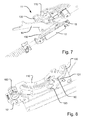
- a lifting device generally designated 10 is mounted between the sash 2 and the frame 1.
- the lifting device 10 in the shown embodiment comprises includes a sash part 12 and a frame part 11 including a spring arrangement 13 and a lifting arm 14 acting between the frame 1 and the sash 2 to provide a spring bias and assist the movement of the sash.
- the spring arrangement 13 is received in a longitudinally extending recess 10a in the frame side member 1a and the frame part 11 of the lifting device 10 in a frame part receiving recess 10b.
- a corresponding lifting device may be provided at each side of the roof window.
- the window is in an open position, in which the sash 2 is still influenced by the lifting device 10.
- the lifting device 10 does not participate in the opening movement, but is ready for re-engagement with the sash, when the sash reaches substantially the same opening angle.
- the lifting arm 14 is affected by a spring bias up until the predefined opening angle, the effect of the spring bias being halted at the predefined opening angle, and the lifting arm 14 is provided with open reception means for engagement means on the sash side member.
- the halting of the spring bias may for instance be provided by the spring assuming its relaxed position, or by providing a stop. As the reception means are open, the engagement means on the sash side member may be received at any time.
- the operating device may be a handle (not shown) connected with the sash bottom member.
- the bias of the lifting device 10 is transmitted to the lifting arm 14.
- the lifting arm 14 exerts a moment on the sash 1, and in combination with the force, and hence moment, exerted by the user operating the operating device, the moment resulting from the weight of the sash 1 and pane 3 is overcome.
- the sledge 15 and the lifting arm 14 are displaced along the sledge guidance 16. All in all, this operation entails that the sash 1 is moved from a closed position to an open position as represented by Fig. 1 , in which the sash plane forms an opening angle with the frame plane.
- Closing the window from the open position entails the opposite movements of the sash 1 and relevant parts of the lifting device. It is possible to position the sash 2 in a number of arbitrary opening positions, in which the sash 2 is held stable relative to the frame 1. Up to the predefined opening angle, in which the lifting arm 14 has reached its stable releasing and receiving position, the lifting arm 14 follows the movement of the sash 2. Opening the window further, the sash 2 is moved out of engagement with the lifting arm 2, but may still be positioned in further arbitrary opening positions.
- the lifting device 10 assumes substantially the same position as shown in Fig. 1 .
- the lifting arm 14 of the lifting device 10 is at a first end 141 connected to the frame part 11 and its opposite, other end 142 is releasably connected with the sash 2 via the sash part 12 of the lifting device 10.
- the lifting arm 14 assumes a stable releasing and receiving position at a predefined opening angle. In the embodiment shown, this predefined opening angle is approximately 45°.
- the predefined opening angle to be defined by the lifting arm 14 may assume any suitable value making it possible to obtain a sufficient opening and at the same time reliable operation of the lifting device.
- the predefined opening angle defined by the lifting arm 14 lies in the range 20° to 80°, preferably 30° to 60°, more preferably 35° to 50°.
- this predefined opening angle has a correlation to the angle formed between a general length direction of the lifting arm 14 and the frame side member 1 a in the stable releasing and receiving position.
- the first end 141 of the lifting arm 14 is rotatably connected to a spring-biased sledge 15 accommodated in a sledge guidance 16 connected to the frame side member 2a, and the opposite, second end 142 includes open reception means, which are here constituted by a fork or cradle 143 adapted to be connected to an engagement means connected to the sash side member 1 a.
- the engagement means of the sash part 12, which in turn is connected to the sash side member 1a in its mounted position, has the form of a rivet 21 connected to a sash hinge part 200 of a hinge fitting of said set of hinges.
- the sledge guidance 16 is, in the embodiment shown connected to the frame hinge part 100 by means of fastening means such as rivets.
- the sledge 15 itself is mounted in a runner 17 fitting slidingly into the sledge guidance 16.
- the lifting arm 14 is spring-biased towards the stable releasing and receiving position at the predefined opening angle by means of a wire spring 150.
- the wire spring 150 has the function of keeping the lifting arm 14 in the correct position at all times.
- the wire spring 150 may as indicated be mounted with a slight inclination to force the lifting arm 14 in the direction of the sash. In this manner, secure engagement of the lifting arm 14 with the rivet 21 is ensured.
- a holding clip 160 adapted to accommodate fastening means for a side frame cladding is connected to the base plate 101 of the frame hinge part 100.
- the rivet 21 constituting the engagement means is connected to the base plate 201 of the sash hinge part 200.
- the rivet 21 is formed with such dimensions that it is able to transmit the load properly into the sash hinge part 200 and further into the sash structure itself.
- the rivet is formed with a collar-like structure in that the rivet 21 is inserted from the back side of the base plate 201 (cf. Fig. 3 ) and abuts against the back side with a first collar part 21 a.
- a second collar part 21 b is formed at the front side of the base plate 201 as shown most clearly in Fig. 6 .
- the hinge axis ⁇ is located between a centre axis and the top of the roof window, preferably in the interval 1/3 to 2/3 of the distance between the centre axis and the top, most preferred substantially at 1/2 of the distance between the centre axis and the top.
- a further aspect of the present invention is conceived in response to the recognition that a pivot hinge fitting as described in the above is subjected to a larger load than other hinges.
- a number of precautions are foreseen in the embodiments shown and described:
- the base plate 101 of the frame hinge part 100 is provided with a distance bushing 170 adapted to abut the frame side member 1 a, viz. in the frame part receiving recess 10b.
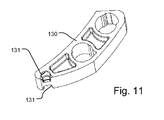
- the base plate 101 of the frame hinge part comprises a reinforcing element 180 adapted to support the guide block 130 of the frame hinge part 100.
- the reinforcing element 180 is received in a recess 131 in the guide block; the guide block 130 is formed with a corresponding recess in the other side as well, cf. Fig. 11 . This makes it possible to utilize one and the same guide block in the left-hand and the right-hand hinge part.
- the reinforcement element 180 may be provided as a separate element connected to the base plate 101, for instance a rivet, but in a presently preferred embodiment, the reinforcement element 180 is provided as a part formed by the material of the base plate itself as shown in the cross-sectional view of Fig. 10 .
- the deformation of the material to provide the reinforcement element 180 may be provided in any suitable manner, for instance by punching or embossing the base plate 101.
- a reinforcement plate 260 (cf. Fig. 3 ) is connected to the base plate 201 of the sash hinge part 200.
- the base plate 201 of the sash hinge part 200 is in a manner known per se provided with a number of spigots 211 and 212 on its back side to be inserted into corresponding bores in the sash side member. Additional separate fastening means such as screws may be present as well to be introduced through the base plate 201 and connected to the sash side member. Alternatively, only separate fastening means may be utilized. However, all of these fastening means are located within the contours of the base plate 201 itself. In particular, the spigots 211 and 212 are virtually located along the same longitudinal position of the sash side member.
- the pivot hinge in the embodiment shown is provided with additional fastening means displaced from the base plate 201, and the reinforcement plate 260 is thus provided with an aperture 213 adapted to receive supplemental fastening means displaced from the base plate 201 of the sash hinge part 200.
- the supplemental fastening means introduced through the displaced aperture 213 is thus positioned in another grain than the spigots 211 and 212 located within the contour of the base plate.
- the frame hinge part 100 is provided with a spigot 111, and the spigot 111 together with the connection between the frame hinge part 100 and the sledge guidance 16 of the above embodiment transfer the load that the frame hinge part 100 is subjected to, further into the frame structure.
- the sledge guidance 16 and other parts of the lifting device, such as the spring arrangement 13 is as described in the above received in the longitudinally extending recess 10a in the frame side member 1 a and the frame part 11 of the lifting device 10 in the frame part receiving recess 10b. This provides for a satisfying distribution and transfer of the load into the frame structure.
Landscapes
- Engineering & Computer Science (AREA)
- Mechanical Engineering (AREA)
- Architecture (AREA)
- Civil Engineering (AREA)
- Structural Engineering (AREA)
- Hinges (AREA)
Priority Applications (1)
| Application Number | Priority Date | Filing Date | Title |
|---|---|---|---|
| PL13199396T PL2770146T3 (pl) | 2013-02-22 | 2013-12-23 | Ulepszony łącznik zawiasowy trzpieniowy oraz okno dachowe mające taki łącznik zawiasowy trzpieniowy |
Applications Claiming Priority (1)
| Application Number | Priority Date | Filing Date | Title |
|---|---|---|---|
| DK201370100A DK178257B1 (en) | 2013-02-22 | 2013-02-22 | A pivot hinge fitting and a roof window comprising such a hinge fitting |
Publications (2)
| Publication Number | Publication Date |
|---|---|
| EP2770146A1 true EP2770146A1 (fr) | 2014-08-27 |
| EP2770146B1 EP2770146B1 (fr) | 2018-02-14 |
Family
ID=49841595
Family Applications (1)
| Application Number | Title | Priority Date | Filing Date |
|---|---|---|---|
| EP13199396.6A Active EP2770146B1 (fr) | 2013-02-22 | 2013-12-23 | Ferrure d'articulation de pivotement amélioré et fenêtre de toit comprenant une telle ferrure |
Country Status (3)
| Country | Link |
|---|---|
| EP (1) | EP2770146B1 (fr) |
| DK (1) | DK178257B1 (fr) |
| PL (1) | PL2770146T3 (fr) |
Cited By (11)
| Publication number | Priority date | Publication date | Assignee | Title |
|---|---|---|---|---|
| WO2017076416A1 (fr) | 2015-11-06 | 2017-05-11 | Vkr Holding A/S | Charnière pour lucarne et lucarne comprenant un ensemble de charnières |
| EP3299536A1 (fr) | 2016-09-23 | 2018-03-28 | VKR Holding A/S | Fenêtre de toit comprenant un ensemble de charnières ayant une séquence de mouvement améliorée |
| DE202017106967U1 (de) | 2016-11-18 | 2018-04-13 | Vkr Holding A/S | Eine Scharnieranordnung mit bogenförmigen Führungsmitteln und einer Bremseinrichtung, sowie ein Dachfenster mit einer derartigen Scharnieranordnung |
| WO2018202915A1 (fr) | 2017-05-05 | 2018-11-08 | Vkr Holding A/S | Charnière pour une fenêtre, fenêtre comprenant un ensemble de telles charnières, et procédé d'installation d'une telle fenêtre |
| EP3730716A1 (fr) | 2018-04-30 | 2020-10-28 | VKR Holding A/S | Fenêtre de toit avec agencement de recouvrement amélioré et procédé de fourniture d'une fenêtre de toit avec agencement de recouvrement amélioré |
| EP3828359A1 (fr) | 2019-11-29 | 2021-06-02 | VKR Holding A/S | Agencement de fenêtre de toit comprenant une pluralité de structures de châssis et un cadre commun et comprenant un ensemble de recouvrement et procédé de fabrication d'un tel agencement de fenêtre de toit |
| WO2022228632A1 (fr) | 2021-04-29 | 2022-11-03 | Vkr Holding A/S | Charnière pour une fenêtre de toit et fenêtre de toit avec un ensemble de charnières |
| WO2022228634A1 (fr) | 2021-04-29 | 2022-11-03 | Vkr Holding A/S | Charnière pour fenêtre de toit et fenêtre de toit comprenant un ensemble de charnières |
| WO2022228635A1 (fr) | 2021-04-29 | 2022-11-03 | Vkr Holding A/S | Fenêtre de toit dotée d'un ensemble de charnières |
| WO2022228633A1 (fr) | 2021-04-29 | 2022-11-03 | Vkr Holding A/S | Charnière pour fenêtre de toit et fenêtre de toit dotée d'un ensemble de charnières |
| EP4257772A1 (fr) | 2022-03-31 | 2023-10-11 | VKR Holding A/S | Agencement de fenêtre de toit comprenant une pluralité d'unités de fenêtre et un cadre commun, et procédé d'installation d'un tel agencement de fenêtre de toit |
Citations (4)
| Publication number | Priority date | Publication date | Assignee | Title |
|---|---|---|---|---|
| US4055024A (en) * | 1975-05-03 | 1977-10-25 | Wilh. Frank Gmbh | Roof window arrangement |
| EP1781883A1 (fr) * | 2004-07-02 | 2007-05-09 | VKR Holding A/S | Ferrures d'articulation comprenant un element intermediaire, fenetre comportant de telles ferrures d'articulation et utilisation d'une telle ferrure d'articulation |
| WO2010005330A2 (fr) * | 2008-07-11 | 2010-01-14 | Fakro Pp Spolka Z O. O. | Châssis de fenêtre en bois, en particulier pour une fenêtre de toit |
| WO2010005331A1 (fr) * | 2008-07-11 | 2010-01-14 | Fakro Pp Spolka Z O. O. | Charnière d'un châssis à pivot de lucarne et unité pour fixer la charnière au cadre, en particulier d'un châssis de lucarne |
Family Cites Families (1)
| Publication number | Priority date | Publication date | Assignee | Title |
|---|---|---|---|---|
| PL215150B1 (pl) * | 2006-07-24 | 2013-10-31 | Fakro Pp Spolka Z Ograniczona Odpowiedzialnoscia | Zawias do okna dachowego ze skrzydlem obrotowym i sposób osadzania zawiasu w oknie dachowym, zwlaszcza wykonanym z ksztaltowników wielokomorowych z tworzywa sztucznego |
-
2013
- 2013-02-22 DK DK201370100A patent/DK178257B1/en active
- 2013-12-23 EP EP13199396.6A patent/EP2770146B1/fr active Active
- 2013-12-23 PL PL13199396T patent/PL2770146T3/pl unknown
Patent Citations (4)
| Publication number | Priority date | Publication date | Assignee | Title |
|---|---|---|---|---|
| US4055024A (en) * | 1975-05-03 | 1977-10-25 | Wilh. Frank Gmbh | Roof window arrangement |
| EP1781883A1 (fr) * | 2004-07-02 | 2007-05-09 | VKR Holding A/S | Ferrures d'articulation comprenant un element intermediaire, fenetre comportant de telles ferrures d'articulation et utilisation d'une telle ferrure d'articulation |
| WO2010005330A2 (fr) * | 2008-07-11 | 2010-01-14 | Fakro Pp Spolka Z O. O. | Châssis de fenêtre en bois, en particulier pour une fenêtre de toit |
| WO2010005331A1 (fr) * | 2008-07-11 | 2010-01-14 | Fakro Pp Spolka Z O. O. | Charnière d'un châssis à pivot de lucarne et unité pour fixer la charnière au cadre, en particulier d'un châssis de lucarne |
Cited By (23)
| Publication number | Priority date | Publication date | Assignee | Title |
|---|---|---|---|---|
| EP3702564A1 (fr) | 2015-11-06 | 2020-09-02 | VKR Holding A/S | Charnière pour une fenêtre de toit et fenêtre de toit comprenant un ensemble de charnières |
| EP3702563A1 (fr) | 2015-11-06 | 2020-09-02 | VKR Holding A/S | Charnière pour une fenêtre de toit et fenêtre de toit comprenant un ensemble de charnières |
| WO2017076416A1 (fr) | 2015-11-06 | 2017-05-11 | Vkr Holding A/S | Charnière pour lucarne et lucarne comprenant un ensemble de charnières |
| DK201670757A1 (en) * | 2016-09-23 | 2018-04-16 | Vkr Holding As | A roof window including a set of hinges with improved movement pattern |
| EP3299536A1 (fr) | 2016-09-23 | 2018-03-28 | VKR Holding A/S | Fenêtre de toit comprenant un ensemble de charnières ayant une séquence de mouvement améliorée |
| EP3299536B1 (fr) * | 2016-09-23 | 2019-12-11 | VKR Holding A/S | Fenêtre de toit comprenant un ensemble de charnières ayant une séquence de mouvement améliorée |
| DE202017106974U1 (de) | 2016-11-18 | 2018-04-13 | Vkr Holding A/S | Eine Scharnieranordnung mit einer Übertragungseinrichtung und einer Vorspanneinrichtung, sowie ein Dachfenster mit einer derartigen Scharnieranordnung |
| EP3842610A1 (fr) | 2016-11-18 | 2021-06-30 | VKR Holding A/S | Système de charnière d'une fenêtre de toit à opérabilité améliorée |
| EP3323968A1 (fr) | 2016-11-18 | 2018-05-23 | VKR Holding A/S | Système de charnière d'une fenêtre de toit à opérabilité améliorée |
| DE202017106972U1 (de) | 2016-11-18 | 2018-04-13 | Vkr Holding A/S | Eine Scharnieranordnung mit einer Laufbahn und einer Vorspanneinrichtung, sowie ein Dachfenster mit einer derartigen Scharnieranordnung |
| DE202017106969U1 (de) | 2016-11-18 | 2018-04-13 | Vkr Holding A/S | Eine Scharnieranordnung mit einer Bremseinrichtung und einer Vorspanneinrichtung, sowie ein Dachfenster mit einer derartigen Scharnieranordnung |
| DE202017106967U1 (de) | 2016-11-18 | 2018-04-13 | Vkr Holding A/S | Eine Scharnieranordnung mit bogenförmigen Führungsmitteln und einer Bremseinrichtung, sowie ein Dachfenster mit einer derartigen Scharnieranordnung |
| US11028627B2 (en) | 2017-05-05 | 2021-06-08 | Vkr Holding A/S | Hinge for a window, a window including a set of such hinges, and a method of installing such a window |
| WO2018202915A1 (fr) | 2017-05-05 | 2018-11-08 | Vkr Holding A/S | Charnière pour une fenêtre, fenêtre comprenant un ensemble de telles charnières, et procédé d'installation d'une telle fenêtre |
| EP3730716A1 (fr) | 2018-04-30 | 2020-10-28 | VKR Holding A/S | Fenêtre de toit avec agencement de recouvrement amélioré et procédé de fourniture d'une fenêtre de toit avec agencement de recouvrement amélioré |
| EP3828359A1 (fr) | 2019-11-29 | 2021-06-02 | VKR Holding A/S | Agencement de fenêtre de toit comprenant une pluralité de structures de châssis et un cadre commun et comprenant un ensemble de recouvrement et procédé de fabrication d'un tel agencement de fenêtre de toit |
| WO2022228632A1 (fr) | 2021-04-29 | 2022-11-03 | Vkr Holding A/S | Charnière pour une fenêtre de toit et fenêtre de toit avec un ensemble de charnières |
| WO2022228634A1 (fr) | 2021-04-29 | 2022-11-03 | Vkr Holding A/S | Charnière pour fenêtre de toit et fenêtre de toit comprenant un ensemble de charnières |
| WO2022228635A1 (fr) | 2021-04-29 | 2022-11-03 | Vkr Holding A/S | Fenêtre de toit dotée d'un ensemble de charnières |
| WO2022228633A1 (fr) | 2021-04-29 | 2022-11-03 | Vkr Holding A/S | Charnière pour fenêtre de toit et fenêtre de toit dotée d'un ensemble de charnières |
| EP4365396A2 (fr) | 2021-04-29 | 2024-05-08 | VKR Holding A/S | Charnière pour fenêtre de toit et fenêtre de toit dotée d'un ensemble de charnières |
| EP4365398A2 (fr) | 2021-04-29 | 2024-05-08 | VKR Holding A/S | Charnière pour fenêtre de toit et fenêtre de toit dotée d'un ensemble de charnières |
| EP4257772A1 (fr) | 2022-03-31 | 2023-10-11 | VKR Holding A/S | Agencement de fenêtre de toit comprenant une pluralité d'unités de fenêtre et un cadre commun, et procédé d'installation d'un tel agencement de fenêtre de toit |
Also Published As
| Publication number | Publication date |
|---|---|
| DK178257B1 (en) | 2015-10-12 |
| EP2770146B1 (fr) | 2018-02-14 |
| DK201370100A (en) | 2014-08-23 |
| PL2770146T3 (pl) | 2018-07-31 |
Similar Documents
| Publication | Publication Date | Title |
|---|---|---|
| EP2770146B1 (fr) | Ferrure d'articulation de pivotement amélioré et fenêtre de toit comprenant une telle ferrure | |
| EP2770149B1 (fr) | Fenêtre de toit avec dispositif de levage et connexion de charnière | |
| US6438795B1 (en) | Buffer device | |
| US20180230729A1 (en) | Hinge device with long reciprocating stroke of a front panel | |
| CN101680475B (zh) | 带有线状形式的移动门件的竖形钩锁件 | |
| EP2295692B1 (fr) | Porte ou ouvrant pour appareils électroménagers | |
| JP2009543724A (ja) | スプリングバイアスプロップアームを備える統合ヒンジアセンブリ | |
| KR102010377B1 (ko) | 회동식 창호시스템의 창호스테이바 유닛 | |
| US11060336B2 (en) | Window stay | |
| JP4847209B2 (ja) | 開き戸の緩衝装置 | |
| PH12014000082A1 (en) | Hatch cover apparatus for vessel | |
| EP3027833B1 (fr) | Dispositif de guidage amélioré pour l'ouverture et le support de portes de meubles | |
| EP1899563A2 (fr) | Charniere | |
| EP3497294B1 (fr) | Système de levage pour battants de porte de meubles pivotant autour d'au moins un axe horizontal | |
| CN107060542A (zh) | 一种窗用滑撑铰链的滑块以及滑撑铰链 | |
| CN205344896U (zh) | 一种动车组用轻型包间拉门 | |
| FR2951489A1 (fr) | Mecanisme d'ouverture des portes avec le pied | |
| EP2762665B1 (fr) | Accessoire de charnière à pivot avec moyens d'engagement et fenêtre de toit comprenant un ensemble de ces accessoires de charnière à pivot | |
| EP3091150A1 (fr) | Ensemble de verrouillage | |
| CN211851366U (zh) | 一种增加承重的隐藏式铰链 | |
| EP2000612B1 (fr) | Échafaudage avec jambes verrouillables | |
| EP1333138A3 (fr) | Serrure encastrée pour fenêtres, portes ou similaires | |
| US9353538B1 (en) | Stiffening strut for garage door panels | |
| CN212867212U (zh) | 窗用滑撑铰链 | |
| CN212814852U (zh) | 一种自动伞的控制结构 |
Legal Events
| Date | Code | Title | Description |
|---|---|---|---|
| PUAI | Public reference made under article 153(3) epc to a published international application that has entered the european phase |
Free format text: ORIGINAL CODE: 0009012 |
|
| 17P | Request for examination filed |
Effective date: 20131223 |
|
| AK | Designated contracting states |
Kind code of ref document: A1 Designated state(s): AL AT BE BG CH CY CZ DE DK EE ES FI FR GB GR HR HU IE IS IT LI LT LU LV MC MK MT NL NO PL PT RO RS SE SI SK SM TR |
|
| AX | Request for extension of the european patent |
Extension state: BA ME |
|
| R17P | Request for examination filed (corrected) |
Effective date: 20150227 |
|
| RBV | Designated contracting states (corrected) |
Designated state(s): AL AT BE BG CH CY CZ DE DK EE ES FI FR GB GR HR HU IE IS IT LI LT LU LV MC MK MT NL NO PL PT RO RS SE SI SK SM TR |
|
| 17Q | First examination report despatched |
Effective date: 20160530 |
|
| GRAP | Despatch of communication of intention to grant a patent |
Free format text: ORIGINAL CODE: EPIDOSNIGR1 |
|
| INTG | Intention to grant announced |
Effective date: 20170908 |
|
| RIN1 | Information on inventor provided before grant (corrected) |
Inventor name: HOLM, MICHAEL GALSGARD Inventor name: HEDE, LASSE VINTHER Inventor name: VESTERBY, LASSE |
|
| GRAS | Grant fee paid |
Free format text: ORIGINAL CODE: EPIDOSNIGR3 |
|
| GRAA | (expected) grant |
Free format text: ORIGINAL CODE: 0009210 |
|
| AK | Designated contracting states |
Kind code of ref document: B1 Designated state(s): AL AT BE BG CH CY CZ DE DK EE ES FI FR GB GR HR HU IE IS IT LI LT LU LV MC MK MT NL NO PL PT RO RS SE SI SK SM TR |
|
| REG | Reference to a national code |
Ref country code: GB Ref legal event code: FG4D |
|
| REG | Reference to a national code |
Ref country code: CH Ref legal event code: EP |
|
| REG | Reference to a national code |
Ref country code: IE Ref legal event code: FG4D |
|
| REG | Reference to a national code |
Ref country code: DE Ref legal event code: R096 Ref document number: 602013033063 Country of ref document: DE Ref country code: AT Ref legal event code: REF Ref document number: 969936 Country of ref document: AT Kind code of ref document: T Effective date: 20180315 |
|
| REG | Reference to a national code |
Ref country code: NL Ref legal event code: MP Effective date: 20180214 |
|
| REG | Reference to a national code |
Ref country code: AT Ref legal event code: MK05 Ref document number: 969936 Country of ref document: AT Kind code of ref document: T Effective date: 20180214 |
|
| PG25 | Lapsed in a contracting state [announced via postgrant information from national office to epo] |
Ref country code: NO Free format text: LAPSE BECAUSE OF FAILURE TO SUBMIT A TRANSLATION OF THE DESCRIPTION OR TO PAY THE FEE WITHIN THE PRESCRIBED TIME-LIMIT Effective date: 20180514 Ref country code: HR Free format text: LAPSE BECAUSE OF FAILURE TO SUBMIT A TRANSLATION OF THE DESCRIPTION OR TO PAY THE FEE WITHIN THE PRESCRIBED TIME-LIMIT Effective date: 20180214 Ref country code: CY Free format text: LAPSE BECAUSE OF FAILURE TO SUBMIT A TRANSLATION OF THE DESCRIPTION OR TO PAY THE FEE WITHIN THE PRESCRIBED TIME-LIMIT Effective date: 20180214 Ref country code: NL Free format text: LAPSE BECAUSE OF FAILURE TO SUBMIT A TRANSLATION OF THE DESCRIPTION OR TO PAY THE FEE WITHIN THE PRESCRIBED TIME-LIMIT Effective date: 20180214 Ref country code: LT Free format text: LAPSE BECAUSE OF FAILURE TO SUBMIT A TRANSLATION OF THE DESCRIPTION OR TO PAY THE FEE WITHIN THE PRESCRIBED TIME-LIMIT Effective date: 20180214 Ref country code: ES Free format text: LAPSE BECAUSE OF FAILURE TO SUBMIT A TRANSLATION OF THE DESCRIPTION OR TO PAY THE FEE WITHIN THE PRESCRIBED TIME-LIMIT Effective date: 20180214 Ref country code: FI Free format text: LAPSE BECAUSE OF FAILURE TO SUBMIT A TRANSLATION OF THE DESCRIPTION OR TO PAY THE FEE WITHIN THE PRESCRIBED TIME-LIMIT Effective date: 20180214 |
|
| PG25 | Lapsed in a contracting state [announced via postgrant information from national office to epo] |
Ref country code: RS Free format text: LAPSE BECAUSE OF FAILURE TO SUBMIT A TRANSLATION OF THE DESCRIPTION OR TO PAY THE FEE WITHIN THE PRESCRIBED TIME-LIMIT Effective date: 20180214 Ref country code: AT Free format text: LAPSE BECAUSE OF FAILURE TO SUBMIT A TRANSLATION OF THE DESCRIPTION OR TO PAY THE FEE WITHIN THE PRESCRIBED TIME-LIMIT Effective date: 20180214 Ref country code: LV Free format text: LAPSE BECAUSE OF FAILURE TO SUBMIT A TRANSLATION OF THE DESCRIPTION OR TO PAY THE FEE WITHIN THE PRESCRIBED TIME-LIMIT Effective date: 20180214 Ref country code: SE Free format text: LAPSE BECAUSE OF FAILURE TO SUBMIT A TRANSLATION OF THE DESCRIPTION OR TO PAY THE FEE WITHIN THE PRESCRIBED TIME-LIMIT Effective date: 20180214 Ref country code: GR Free format text: LAPSE BECAUSE OF FAILURE TO SUBMIT A TRANSLATION OF THE DESCRIPTION OR TO PAY THE FEE WITHIN THE PRESCRIBED TIME-LIMIT Effective date: 20180515 Ref country code: BG Free format text: LAPSE BECAUSE OF FAILURE TO SUBMIT A TRANSLATION OF THE DESCRIPTION OR TO PAY THE FEE WITHIN THE PRESCRIBED TIME-LIMIT Effective date: 20180514 |
|
| PG25 | Lapsed in a contracting state [announced via postgrant information from national office to epo] |
Ref country code: AL Free format text: LAPSE BECAUSE OF FAILURE TO SUBMIT A TRANSLATION OF THE DESCRIPTION OR TO PAY THE FEE WITHIN THE PRESCRIBED TIME-LIMIT Effective date: 20180214 Ref country code: IT Free format text: LAPSE BECAUSE OF FAILURE TO SUBMIT A TRANSLATION OF THE DESCRIPTION OR TO PAY THE FEE WITHIN THE PRESCRIBED TIME-LIMIT Effective date: 20180214 Ref country code: EE Free format text: LAPSE BECAUSE OF FAILURE TO SUBMIT A TRANSLATION OF THE DESCRIPTION OR TO PAY THE FEE WITHIN THE PRESCRIBED TIME-LIMIT Effective date: 20180214 Ref country code: RO Free format text: LAPSE BECAUSE OF FAILURE TO SUBMIT A TRANSLATION OF THE DESCRIPTION OR TO PAY THE FEE WITHIN THE PRESCRIBED TIME-LIMIT Effective date: 20180214 |
|
| REG | Reference to a national code |
Ref country code: DE Ref legal event code: R097 Ref document number: 602013033063 Country of ref document: DE |
|
| PG25 | Lapsed in a contracting state [announced via postgrant information from national office to epo] |
Ref country code: SM Free format text: LAPSE BECAUSE OF FAILURE TO SUBMIT A TRANSLATION OF THE DESCRIPTION OR TO PAY THE FEE WITHIN THE PRESCRIBED TIME-LIMIT Effective date: 20180214 Ref country code: CZ Free format text: LAPSE BECAUSE OF FAILURE TO SUBMIT A TRANSLATION OF THE DESCRIPTION OR TO PAY THE FEE WITHIN THE PRESCRIBED TIME-LIMIT Effective date: 20180214 Ref country code: DK Free format text: LAPSE BECAUSE OF FAILURE TO SUBMIT A TRANSLATION OF THE DESCRIPTION OR TO PAY THE FEE WITHIN THE PRESCRIBED TIME-LIMIT Effective date: 20180214 Ref country code: SK Free format text: LAPSE BECAUSE OF FAILURE TO SUBMIT A TRANSLATION OF THE DESCRIPTION OR TO PAY THE FEE WITHIN THE PRESCRIBED TIME-LIMIT Effective date: 20180214 |
|
| PLBE | No opposition filed within time limit |
Free format text: ORIGINAL CODE: 0009261 |
|
| STAA | Information on the status of an ep patent application or granted ep patent |
Free format text: STATUS: NO OPPOSITION FILED WITHIN TIME LIMIT |
|
| 26N | No opposition filed |
Effective date: 20181115 |
|
| PG25 | Lapsed in a contracting state [announced via postgrant information from national office to epo] |
Ref country code: SI Free format text: LAPSE BECAUSE OF FAILURE TO SUBMIT A TRANSLATION OF THE DESCRIPTION OR TO PAY THE FEE WITHIN THE PRESCRIBED TIME-LIMIT Effective date: 20180214 |
|
| REG | Reference to a national code |
Ref country code: CH Ref legal event code: PL |
|
| PG25 | Lapsed in a contracting state [announced via postgrant information from national office to epo] |
Ref country code: MC Free format text: LAPSE BECAUSE OF FAILURE TO SUBMIT A TRANSLATION OF THE DESCRIPTION OR TO PAY THE FEE WITHIN THE PRESCRIBED TIME-LIMIT Effective date: 20180214 Ref country code: LU Free format text: LAPSE BECAUSE OF NON-PAYMENT OF DUE FEES Effective date: 20181223 |
|
| REG | Reference to a national code |
Ref country code: IE Ref legal event code: MM4A |
|
| REG | Reference to a national code |
Ref country code: BE Ref legal event code: MM Effective date: 20181231 |
|
| PG25 | Lapsed in a contracting state [announced via postgrant information from national office to epo] |
Ref country code: IE Free format text: LAPSE BECAUSE OF NON-PAYMENT OF DUE FEES Effective date: 20181223 |
|
| PG25 | Lapsed in a contracting state [announced via postgrant information from national office to epo] |
Ref country code: BE Free format text: LAPSE BECAUSE OF NON-PAYMENT OF DUE FEES Effective date: 20181231 |
|
| PG25 | Lapsed in a contracting state [announced via postgrant information from national office to epo] |
Ref country code: CH Free format text: LAPSE BECAUSE OF NON-PAYMENT OF DUE FEES Effective date: 20181231 Ref country code: LI Free format text: LAPSE BECAUSE OF NON-PAYMENT OF DUE FEES Effective date: 20181231 |
|
| PG25 | Lapsed in a contracting state [announced via postgrant information from national office to epo] |
Ref country code: MT Free format text: LAPSE BECAUSE OF NON-PAYMENT OF DUE FEES Effective date: 20181223 |
|
| PG25 | Lapsed in a contracting state [announced via postgrant information from national office to epo] |
Ref country code: TR Free format text: LAPSE BECAUSE OF FAILURE TO SUBMIT A TRANSLATION OF THE DESCRIPTION OR TO PAY THE FEE WITHIN THE PRESCRIBED TIME-LIMIT Effective date: 20180214 |
|
| PG25 | Lapsed in a contracting state [announced via postgrant information from national office to epo] |
Ref country code: PT Free format text: LAPSE BECAUSE OF FAILURE TO SUBMIT A TRANSLATION OF THE DESCRIPTION OR TO PAY THE FEE WITHIN THE PRESCRIBED TIME-LIMIT Effective date: 20180214 |
|
| PG25 | Lapsed in a contracting state [announced via postgrant information from national office to epo] |
Ref country code: HU Free format text: LAPSE BECAUSE OF FAILURE TO SUBMIT A TRANSLATION OF THE DESCRIPTION OR TO PAY THE FEE WITHIN THE PRESCRIBED TIME-LIMIT; INVALID AB INITIO Effective date: 20131223 Ref country code: MK Free format text: LAPSE BECAUSE OF NON-PAYMENT OF DUE FEES Effective date: 20180214 |
|
| PG25 | Lapsed in a contracting state [announced via postgrant information from national office to epo] |
Ref country code: IS Free format text: LAPSE BECAUSE OF FAILURE TO SUBMIT A TRANSLATION OF THE DESCRIPTION OR TO PAY THE FEE WITHIN THE PRESCRIBED TIME-LIMIT Effective date: 20180614 |
|
| PGFP | Annual fee paid to national office [announced via postgrant information from national office to epo] |
Ref country code: GB Payment date: 20231102 Year of fee payment: 11 |
|
| PGFP | Annual fee paid to national office [announced via postgrant information from national office to epo] |
Ref country code: FR Payment date: 20231122 Year of fee payment: 11 Ref country code: DE Payment date: 20231031 Year of fee payment: 11 |
|
| PGFP | Annual fee paid to national office [announced via postgrant information from national office to epo] |
Ref country code: PL Payment date: 20231116 Year of fee payment: 11 |