EP2769917B1 - Luftmitführungsfiltration für Flugzeugkabine mit Kondensationsablauf - Google Patents
Luftmitführungsfiltration für Flugzeugkabine mit Kondensationsablauf Download PDFInfo
- Publication number
- EP2769917B1 EP2769917B1 EP14156220.7A EP14156220A EP2769917B1 EP 2769917 B1 EP2769917 B1 EP 2769917B1 EP 14156220 A EP14156220 A EP 14156220A EP 2769917 B1 EP2769917 B1 EP 2769917B1
- Authority
- EP
- European Patent Office
- Prior art keywords
- air
- cabin
- housing
- housing interior
- aircraft
- Prior art date
- Legal status (The legal status is an assumption and is not a legal conclusion. Google has not performed a legal analysis and makes no representation as to the accuracy of the status listed.)
- Active
Links
Images


Classifications
-
- B—PERFORMING OPERATIONS; TRANSPORTING
- B64—AIRCRAFT; AVIATION; COSMONAUTICS
- B64D—EQUIPMENT FOR FITTING IN OR TO AIRCRAFT; FLIGHT SUITS; PARACHUTES; ARRANGEMENT OR MOUNTING OF POWER PLANTS OR PROPULSION TRANSMISSIONS IN AIRCRAFT
- B64D13/00—Arrangements or adaptations of air-treatment apparatus for aircraft crew or passengers, or freight space
- B64D13/06—Arrangements or adaptations of air-treatment apparatus for aircraft crew or passengers, or freight space the air being conditioned
- B64D2013/0603—Environmental Control Systems
- B64D2013/0625—Environmental Control Systems comprising means for distribution effusion of conditioned air in the cabin
-
- B—PERFORMING OPERATIONS; TRANSPORTING
- B64—AIRCRAFT; AVIATION; COSMONAUTICS
- B64D—EQUIPMENT FOR FITTING IN OR TO AIRCRAFT; FLIGHT SUITS; PARACHUTES; ARRANGEMENT OR MOUNTING OF POWER PLANTS OR PROPULSION TRANSMISSIONS IN AIRCRAFT
- B64D13/00—Arrangements or adaptations of air-treatment apparatus for aircraft crew or passengers, or freight space
- B64D13/06—Arrangements or adaptations of air-treatment apparatus for aircraft crew or passengers, or freight space the air being conditioned
- B64D2013/0603—Environmental Control Systems
- B64D2013/0651—Environmental Control Systems comprising filters, e.g. dust filters
-
- B—PERFORMING OPERATIONS; TRANSPORTING
- B64—AIRCRAFT; AVIATION; COSMONAUTICS
- B64D—EQUIPMENT FOR FITTING IN OR TO AIRCRAFT; FLIGHT SUITS; PARACHUTES; ARRANGEMENT OR MOUNTING OF POWER PLANTS OR PROPULSION TRANSMISSIONS IN AIRCRAFT
- B64D13/00—Arrangements or adaptations of air-treatment apparatus for aircraft crew or passengers, or freight space
- B64D13/06—Arrangements or adaptations of air-treatment apparatus for aircraft crew or passengers, or freight space the air being conditioned
- B64D2013/0603—Environmental Control Systems
- B64D2013/0688—Environmental Control Systems with means for recirculating cabin air
Definitions
- the present invention pertains to an aircraft cabin ventilation system that uses the momentum of a jet of air ejected from a nozzle to draw cabin air through a filter or other device to sanitize the air before returning it to the cabin, thereby increasing the total apparent ventilation rate to the cabin without enlarging the ventilation system of the aircraft.
- the present invention pertains to a ventilation system that employs a plurality of nozzles positioned in a cavity between a sidewall of the aircraft cabin and a section of the aircraft fuselage. The nozzles receive a supply of ventilation air and direct jets of air from the cavity and into the aircraft cabin, with the jets of air creating low pressure areas in the cavity.
- Ventilation openings in the cabin sidewall communicate the low pressure areas with the cabin interior, whereby the low pressure areas draw air from the cabin interior into the cavity where the drawn air is entrained into the jets of air produced by the nozzles.
- Devices inside the cavity remove suspend impurities from the air drawn into the cavity.
- the ventilation system of the invention filters or sanitizes the air drawn through the system and thereby increases the total apparent ventilation rate to the aircraft cabin without enlarging the ventilation system of the aircraft.
- the potential problem of airborne disease or other air suspended impurities in the cabin of an aircraft is mitigated by dilution ventilation.
- the removal of microbials from the breathing space of an aircraft cabin reduces the risk of airborne infection.
- Current disease models suggest that some benefit is obtained by increasing the flow of pathogen free air to the aircraft cabin.
- Current ventilation air distribution systems provide between 15 and 25 cfm per passenger in economy seating. The ventilation air distribution systems are flowing at the maximum capacity of the ducting of the system and the system fans. Thus, the limited capacity of current air distribution systems in passenger aircraft is a primary problem in reducing the risk of airborne infection.
- One solution is to reduce the passenger count, thereby increasing the ventilation flow per person.
- reducing the passenger count is not a popular solution because it drives up the cost of the airline ticket proportionately, wastes fuel, and causes flight delays through the increased aircraft traffic resulting from reducing the number of passengers in each aircraft.
- Ultraviolet light sterilizers irradiating ventilation air are very effective in providing pathogen free ventilation air. However, exposing the passengers to the radiation of ultraviolet light is not acceptable.
- Filter material for example felt, could be added to the air ventilation distribution system to remove air suspended impurities.
- the filter material would absorb moisture from the cool ventilation air, thereby becoming a source of bacterial growth.
- the wet filter material could present the problem of condensation dripping on passengers during open door loading in the humid
- an aircraft is provided with an apparatus that reduces the transfer of air suspended impurities in a cabin of an aircraft without increasing the capacity of the existing air distribution system of the aircraft.
- the apparatus includes a housing configured to be positioned in a cavity of the aircraft between a sidewall of the cabin and a section of a fuselage of the aircraft, the housing comprising:an interior; a lower portion having a first sidewall; and an upper portion that extends upwardly from the lower portion to an air outlet opening, wherein the air outlet opening is configured to communicate the housing interior with a cabin interior; a source of ventilation air communicating with a hollow diffuser tube extending longitudinally through the housing interior, wherein the diffuser tube comprises: a plurality of nozzlesdirected upwardly toward the centre of the housing upper portion, the nozzles receiving the ventilation air and directing a jet of air from the housing interior into the cabin, the jet of air creating a low pressure area in the housing interior; a drawn air inlet opening in the first sidewall of the housing configured to communicate with at least one return air opening of the cabin sidewall, thereby communicating the cabin with the low pressure area in the housing interior where the low pressure area in the housing interior draws air from the cabin through the at least one return air opening and
- the device in the housing interior that removes air suspended impurities be a filter, a germicidal lamp, or a combination of both.
- a condensation drain may be provided on the housing of the apparatus.
- the drain allows any moisture that drips from a filter employed in the housing and/or any water that condenses from the cold ventilation air supplied to the nozzle in warm, high humidity environments to drain from the housing.
- a method for reducing transfer of air suspended impurities in a cabin of an aircraft comprises positioning a housing between a sidewall of the cabin and a section of a fuselage of the aircraft, wherein the housing comprises an interior, a lower portion having a first sidewall, and an upper portion that extends upwardly from the lower portion to an air outlet opening; supplying a flow of air to a hollow diffuser tube extending longitudinally through the interior of the housing, wherein the diffuser tube comprises a plurality of nozzles; producing a jet of air directed upwardly toward a centre of the upper portion from the plurality of nozzles and into the cabin through the air outlet opening with the jet of air creating a low pressure area within the housing interior; drawing air from the cabin through an air return opening in the sidewall and through a drawn air inlet opening in the first sidewall of the housing and into the low pressure area; irradiating the air drawn into the low pressure area with ultra-violet light; and mixing the irradi
- the method may further comprise filtering the air drawn into the low pressure area and then irradiating the air drawn into the low pressure area.
- the method may further comprise blocking the ultra-violet light from passing through the air return opening and entering the cabin.
- the method may further comprise condensing moisture from the air drawn into the low pressure area; and draining the condensed moisture from the low pressure area.
- the method may further comprise drawing air from the cabin to supply the flow of air to the nozzle.
- the housing of the apparatus may be one of a plurality of separate housings positioned between the sidewall of the cabin and the section of the fuselage of the aircraft, each housing of the plurality of housings having the features mentioned above.
- the apparatus of the invention increases the total apparent filtered ventilation air to the aircraft cabin without enlarging the ventilation system of the aircraft.
- the aircraft of the present invention is provided with an apparatus that reduces the transfer of air suspended impurities in a cabin of an aircraft without increasing the capacity of the existing air distribution system of the aircraft.
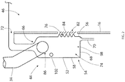
- Figure 1 is a representation of a cross-section view of an aircraft 12 employing the cabin air entrainment filtration system with a condensation drain of the apparatus of the invention.
- the aircraft 12 is basically comprised of a floor having a floor surface 14, and cabin sidewalls 16, 18 extending around opposite sides of the aircraft cabin interior 22. Sections of the aircraft fuselage 24, 26 extend around the respective sidewalls 16, 18 and enclose cavities 28, 30 between the sidewalls 16, 18 and the sections of fuselage 24, 26.
- the ventilation system of the aircraft 12 includes a source of ventilation air 32 represented schematically in Figure 1 .
- the source of ventilation air 32 provides a flow of cool ventilation air to the aircraft cabin interior.
- the flow of ventilation air is supplied from the air source 32 to air flow ducts 34, 36 (also referred to as "ventilation air supply ducts") that extend through the cavities 28, 30 between the respective cabin sidewalls 16, 18 and the exterior sections of the aircraft fuselage 24, 26.
- the flow of ventilation air from the source of ventilation 32 can be driven by one or more fans or other equivalent means currently employed in aircraft.
- the flow of ventilation air is directed through a plurality of ducts 34, 36 and into the cabin interior 22 through a plurality of air outlet openings in the cabin sidewalls 16, 18 just below the stowage bins 38, 40 of the aircraft.
- ducts 34, 36 are shown in Figure 1 extending through the respective cavities 28, 30 in the laterally opposite sides of the aircraft 12, the source of ventilation 32 could be providing flows of cool ventilation air through pluralities of similar ducts that are spatially arranged in the cavities along the longitudinal length of the aircraft.
- the apparatus 44 will be described in association with only one of the air ducts 34 that extends through the cavity 28 between the cabin sidewall 16 and the aircraft fuselage section 24. It should be understood that the apparatus 44 can be employed with each of the plurality of air ducts 34, 36 positioned in the cavities 28, 30 between the respective cabin sidewalls 16, 18 and the aircraft fuselage sections 24, 26. Thus, a plurality of the apparatus 44 would be positioned along the cavities 28, 30.
- Figure 1 shows the positioning of the apparatus 44 relative to the aircraft 12.
- the apparatus 44 is positioned in the cavity 28 between the cabin sidewall 16 and the aircraft fuselage section 24.
- the apparatus 44 is positioned vertically in the cavity 28 adjacent a passenger breathing zone 46 of the cabin interior.
- the breathing zone 46 is approximately the height of a passenger's head above the floor surface 14 when seated in the aircraft.
- Figure 2 shows an enlarged view of the apparatus 44 positioned to the left in Figure 1 . It should be understood that the apparatus 44 positioned to the right in Figure 1 is a mirror image of that shown in Figure 2 .
- the apparatus 44 includes a housing 52 positioned in the cavity 28 between the cabin sidewall 16 and the aircraft fuselage section 24.
- the housing 52 has a large lower portion 54.
- the lower portion 54 has a general elongate cube configuration defined by lower portions of laterally spaced first 56 and second 58 sidewalls of the housing, lower portions of longitudinally spaced first 62 and second 64 end walls of the housing and a bottom wall 68 of the housing.
- the bottom wall 68 has a drain, such as a drain hole and a drain tube 70, extending downwardly from the bottom wall.
- the drain in the housing drains moisture from the air drawn into the housing interior. As such, the moisture is condensed from the air drawn into the low pressure area, and the condensed moisture is drained from the low pressure area.
- the housing also has a smaller upper portion 66 that extends upwardly from the lower portion 54. As the upper portion 66 extends upwardly the first 56 and second 58 sidewalls of the housing merge toward each other and form the housing upper portion 66 as a narrow flue with a rectangular cross-section.
- the housing upper portion 66 at first extends straight upwardly from the housing lower portion 54, but then bends through a curve as it extends to an air outlet opening 72 at the opposite end of the housing upper portion 66 from the housing lower portion 54.
- the air outlet opening 72 of the housing 52 is positioned in the cabin sidewall 16 just below the stowage bin 38 of the aircraft cabin and communicates an interior volume 74 of the housing 52 with the cabin interior 22.
- a drawn air inlet opening 76 is provided through the first sidewall 56 of the housing 52.
- the drawn air inlet opening 76 has, for example a rectangular configuration and occupies much of the first sidewall 56.
- a filter 78 can be positioned in the drawn air inlet opening 76.
- the filter 78 would provide a device for removing airborne impurities in air drawn into the housing interior 74 through the drawn air inlet opening 76 in a manner to be explained.
- the apparatus 44 could be employed without the filter 78.
- An air return opening 82 is provided in the aircraft cabin sidewall 16 adjacent the drawn air inlet opening 76 of the housing 52.
- the air return opening 82 can be covered with a decorative grill, with louvers, overlapping fins or slats or other equivalent types of ventilating openings 84 that allow air to pass through the openings but block the view of a passenger in the cabin interior 22 into the cavity 28.
- a ventilation air inlet opening 86 is provided in the first end wall 62 of the housing 52. As shown in the drawing figures, the ventilation air inlet opening 86 is positioned in the first end wall 62 toward the top of the lower housing portion 54 where the lower housing portion begins to merge into the upper housing portion 66.
- the ventilation duct 34 extending through the cavity 28 is connected to the first end wall 62 of the housing 52 at the ventilation air inlet opening 86. In this manner, the source of ventilation air 32 communicates through the duct 34 with the housing interior 74 and supplies a flow of air through the duct 34 and the ventilation air inlet opening 86 to the housing interior 74.
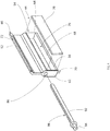
- a hollow diffuser tube 92 extends longitudinally through the housing interior 74. Opposite ends of the diffuser tube 92 are connected to the opposed interior surfaces of the first end wall 62 and the second end wall 64 of the housing.
- the hollow interior 94 of the diffuser tube 92 communicates through the ventilation air inlet opening 86 in the housing first end wall 62 with the ventilation air duct 34 connected to the housing.
- the diffuser tube 92 is straight and extends straight through the housing. Other equivalent configurations of the diffuser tube could be employed other than that shown. With the diffuser tube 92 communicating with the ventilation air inlet opening 86, the diffuser tube 92 is positioned toward the top of the housing lower portion 54 just where the housing lower portion begins to merge into the housing upper portion 66.
- a plurality of holes extend through the top of the diffuser tube 94 and communicate the interior of the diffuser tube with the housing interior 74.
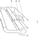
- the plurality of holes form nozzles 96 that are spatially arranged in a straight line across the top of the diffuser tube 92 and are directed upwardly toward the center of the housing upper portion 66. With all of the nozzles 96 directed upwardly through the housing upper portion 66, when a flow of ventilation air from the ventilation air source 32 is directed through the duct 34 and the ventilation air inlet opening 86 into the interior of the diffuser tube 92, the nozzles 96 direct jets of the air 104 (shown in Figure 5 ) upwardly through the interior of the housing upper portion 66 and out through the air outlet opening 72 of the housing into the cabin interior 22.
- the jets of air directed from the nozzles 96 create a low-pressure area 98 in the housing interior 74 toward the bottom of the housing lower portion 54 on an opposite side of the diffuser tube 92 from the nozzles.
- This low-pressure area 98 in the housing interior 74 communicates through the drawn air inlet opening 76 of the housing and the air return opening 82 of the cabin sidewall 16 to draw air from the cabin interior 22 into the low-pressure area 98 of the housing.
- This air drawn into the housing interior 74 is then entrained into the flow of air produced by the jets of air from the nozzles 96 and travels through the housing upper portion 66 and the housing air outlet opening 72 and is returned to the cabin interior 22.
- the low pressure area 98 is an area having a pressure lower than a pressure in the cabin interior 22.
- a device 102 is provided in the housing interior 74 that removes air suspended impurities from the air drawn into the housing interior 74 through the drawn air inlet opening 76 of the housing 52 and the air return opening 82 of the cabin sidewall 16.
- the device 102 could be an additional filter, a germicidal lamp, or a combination of both.
- the device 102 is an ultraviolet light sterilizer that irradiates the air drawn into the low-pressure area 98 of the housing through the housing drawn air inlet opening 76 and the air return opening 82 in the cabin sidewall 16.
- the ultraviolet light destroys microbials and other impurities carried by the air drawn into the low-pressure area 98 of the housing interior that penetrates the filter 78, or pass through the drawn air inlet opening 76 when a filter is not employed.
- the ultraviolet light of the device 102 is positioned in the housing interior 74 where the light cannot pass through the louvers or other equivalent mechanisms of the air return opening 82 in the cabin sidewall 16 and subject passengers to the ultraviolet light or enable the ultraviolet light to be seen by passengers.
- the apparatus 44 described above reduces the transfer of air suspended impurities in the aircraft cabin interior 22.
- the nozzles when a flow of air is supplied from the source of ventilation air 32 through the ducting 34 to the nozzles 96 in the housing interior 74, the nozzles produce jets of air 104 directed from the nozzles into the housing upper portion 66, through the housing air outlet opening 72 and into the aircraft cabin interior 22.
- the jets of air 104 produced by the nozzles 96 also create an area of low pressure 98 in the housing lower portion 54.
- the area of low pressure 98 draws air 106 from the cabin interior 22 through the air return opening 82 in the cabin sidewall 16, through the drawn air inlet opening 76 in the housing 52 and into the low-pressure area 98 of the housing 52.
- the air 106 drawn into the low-pressure area 98 is irradiated with ultraviolet light from the ultraviolet light sterilizer of the device 102.
- the irradiated air 108 is then entrained and mixed with the jets of air 104 from the nozzles 96 and returned with the jets of air to the cabin interior 22.
- the above-described apparatus 44 provides a method for reducing transfer of air suspended impurities in a cabin of an aircraft.
- the method includes positioning a nozzle 96 between a sidewall 16, 18 of the cabin and a section of a fuselage 24, 26 of the aircraft.
- a flow of air is supplied to the nozzle 96 to produce a jet of air 104 directed from the nozzle 96 and into the cabin with the jet of air 104 creating a low pressure area 98 between the sidewall 16, 18 of the cabin and the section of the aircraft 24, 26 fuselage.
- Air 106 is drawn from the cabin through an air return opening 82 in the sidewalls 16, 18 and into the low pressure area 98.
- the air return opening 82 communicates the low pressure area 98 between the sidewall 16, 18 of the cabin and the section of the fuselage 24, 26 of the aircraft 12 with the cabin.
- the method further includes irradiating the air 106 drawn into the low pressure area 98 with ultra-violet light of a device 102, and mixing the irradiated air 108 with the jet of air 104 from the nozzle 96 and returning the irradiated air mixed with the jet of air to the cabin.
- the air 106 drawn into the low pressure area 98 is filtered and then irradiated using the device 102.
- the ultra-violet light is blocked from passing through the air return opening 82 and entering the cabin.
- the method further includes condensing moisture from the air 106 drawn into the low pressure area 98, and draining the condensed moisture from the low pressure area 98.
- the method includes drawing air 106 from the cabin to supply the flow of air 106 to the nozzle 96.
- a plurality of nozzles 96 can be positioned between the sidewall 16, 18 of the cabin and the section of the fuselage 24, 26 of the aircraft 12, and a flow of air can be supplied to the plurality of nozzles 96 to produce jets of air 104 into the cabin with the jets of air 104 producing low pressure areas 98 between the sidewall 16, 18 of the cabin and the section of the fuselage 24, 26 of the aircraft.
- the apparatus of the invention increases the total apparent filtered ventilation air to the aircraft cabin without enlarging the ventilation system of the aircraft.
Landscapes
- Engineering & Computer Science (AREA)
- Health & Medical Sciences (AREA)
- General Health & Medical Sciences (AREA)
- Pulmonology (AREA)
- Aviation & Aerospace Engineering (AREA)
- Ventilation (AREA)
- Chemical & Material Sciences (AREA)
- Combustion & Propulsion (AREA)
- Mechanical Engineering (AREA)
- General Engineering & Computer Science (AREA)
- Filtering Of Dispersed Particles In Gases (AREA)
Claims (12)
- Verfahren zum Reduzieren der Übertragung von schwebenden Verunreinigungen in einer Kabine eines Flugzeugs (12), wobei das Verfahren umfasst:Positionieren eines Gehäuses (52) zwischen einer Seitenwand (16, 18) der Kabine und einem Abschnitt eines Rumpfes (24, 26) des Flugzeugs, wobei das Gehäuse (52) einen Innenraum (74), einen unteren Abschnitt (54) mit einer ersten Seitenwand (56) und einen oberen Abschnitt (66) umfasst, der sich vom unteren Abschnitt (54) nach oben zu einer Luftauslassöffnung (72) erstreckt;Zuführen eines Luftstroms zu einem hohlen Diffusorrohr (92), das sich in Längsrichtung durch das Innere (74) des Gehäuses (52) erstreckt, wobei das Diffusorrohr (92) eine Mehrzahl von Düsen (96) umfasst;Erzeugen eines Luftstrahls (104), der von der Mehrzahl von Düsen nach oben zu einer Mitte des oberen Abschnitts (66) und durch die Luftauslassöffnung (72) in die Kabine gerichtet ist, wobei der Luftstrahl einen Niederdruckbereich (98) innerhalb des Innenraums (74) des Gehäuses erzeugt;Ansaugen von Luft (106) aus der Kabine durch eine Luftrückführungsöffnung (82) in der Seitenwand und durch eine Ansaugluft-Einlassöffnung (76) in der ersten Seitenwand (56) des Gehäuses (52) und in den Niederdruckbereich (98);Bestrahlen der in den Niederdruckbereich (98) eingesaugten Luft mit ultraviolettem Licht; undMischen der bestrahlten Luft (108) mit dem Luftstrahl aus den Düsen und Rückführen der mit dem Luftstrahl gemischten bestrahlten Luft in die Kabine.
- Verfahren nach Anspruch 1, ferner umfassend:
Filtern der in den Niederdruckbereich (98) eingesaugten Luft (106) und anschließendes Bestrahlen der in den Niederdruckbereich eingesaugten Luft. - Verfahren nach Anspruch 1 oder 2, ferner umfassend:
Hindern des ultravioletten Lichts am Passieren der Luftrückführungsöffnung (82) und am Eindringen in die Kabine. - Verfahren nach einem der vorhergehenden Ansprüche, ferner umfassend:Kondensieren von Feuchtigkeit aus der in den Niederdruckbereich (98) eingesaugten Luft (106); undAblassen der kondensierten Feuchtigkeit aus dem Niederdruckbereich.
- Verfahren nach einem vorhergehenden Anspruch, ferner umfassend:
Ansaugen von Luft (106) aus der Kabine, um den Strom der Luft zu den Düsen (96) zu leiten. - Vorrichtung (44) zum Reduzieren der Übertragung von schwebenden Verunreinigungen in einer Kabine eines Flugzeugs (12), wobei die Vorrichtung umfasst:ein Gehäuse (52), das konfiguriert ist, um in einem Hohlraum (28) des Flugzeugs zwischen einer Seitenwand (16, 18) der Kabine und einem Abschnitt eines Rumpfes (24, 26) des Flugzeugs positioniert zu werden, wobei das Gehäuse (52) umfasst:einen Innenraum (74);einen unteren Abschnitt (54) mit einer ersten Seitenwand (56); undeinen oberen Abschnitt (66), der sich vom unteren Abschnitt (54) nach oben zu einer Luftauslassöffnung (72) erstreckt, wobei die Luftauslassöffnung konfiguriert ist, um das Gehäuseinnere (74) mit einem Kabineninneren (22) zu verbinden;eine Quelle für Belüftungsluft (86), die mit einem hohlen Diffusorrohr (92) in Verbindung steht, das sich in Längsrichtung durch das Gehäuseinnere (74) erstreckt, wobei das Diffusorrohr (92) umfasst:
eine Mehrzahl von Düsen (96), die nach oben zur Mitte des oberen Abschnitts (66) des Gehäuses gerichtet sind, wobei die Düsen die Belüftungsluft (32) aufnehmen und einen Luftstrahl (104) aus dem Gehäuseinneren in die Kabine leiten, wobei der Luftstrahl einen Niederdruckbereich (98) in dem Gehäuseinneren erzeugt;eine Ansaugluft-Einlassöffnung (76) in der ersten Seitenwand (56) des Gehäuses (52), die konfiguriert ist, um mit mindestens einer Rückluftöffnung (82) der Kabinenseitenwand verbunden zu sein, wodurch die Kabine mit dem Niederdruckbereich im Gehäuseinnenraum verbunden wird, wo der Niederdruckbereich im Gehäuseinnenraum Luft (106) aus der Kabine durch die mindestens eine Rückluftöffnung und durch die Ansaugluftöffnung (76) in den Gehäuseinnenraum ansaugt; und,eine Vorrichtung (102) innerhalb des Gehäuseinnenraums, die schwebende Verunreinigungen aus der in den Gehäuseinnenraum angesaugten Luft entfernt. - Vorrichtung (44) nach Anspruch 6, bei der die Vorrichtung (102), die schwebende Verunreinigungen in der in den Gehäuseinnenraum angesaugten Luft entfernt, eine keimtötende Lampe umfasst.
- Vorrichtung (44) nach Anspruch 6 oder 7, bei der die Vorrichtung (102), die schwebende Verunreinigungen in der in den Gehäuseinnenraum angesaugten Luft entfernt, einen Filter umfasst.
- Vorrichtung (44) nach einem der Ansprüche 6 bis 8, ferner umfassend:
einen Ablauf in dem Gehäuse (52), der Feuchtigkeit aus der in den Gehäuseinnenraum (74) angesaugten Luft (106) abführt. - Vorrichtung (44) nach einem der Ansprüche 6 bis 9, ferner mit einem Filter (78), der in der Ansaugluft-Einlassöffnung (76) des Gehäuses (52) angeordnet ist.
- Flugzeug mit der Vorrichtung (44) nach Anspruch 6, wobei das Gehäuse (52) durch die Seitenwand mit der Kabine verbunden ist, wobei das Flugzeug ferner umfasst:
einen Lüftungsluftzufuhrkanal (34, 36), der sich zwischen der Seitenwand der Kabine und dem Abschnitt des Flugzeugrumpfes erstreckt, wobei der Lüftungsluftzufuhrkanal mit dem Gehäuse verbunden ist und die Quelle der Lüftungsluft (32) mit dem Gehäuseinneren verbindet, wobei:die Düsen (96) in Verbindung mit dem Lüftungsluftzufuhrkanal angeschlossen sind, wobei die Düsen konstruiert sind, um die durch den Lüftungsluftzufuhrkanal mit dem Gehäuseinnenraum verbundene Lüftungsluftquelle aufzunehmen und den von den Düsen durch den Gehäuseinnenraum und in die Kabine gerichteten Luftstrahl (104) zu erzeugen, unddie mindestens eine Abluftöffnung (82) sich in der Seitenwand der Kabine befindet, wo die Luft (106) in den von den Düsen durch den Gehäuseinnenraum und in die Kabine geleiteten Luftstrahl mitgerissen wird, wenn der Niederdruckbereich (98) die Luft aus der Kabine ansaugt. - Flugzeug nach Anspruch 11, bei dem das Gehäuse (52) eines aus einer Mehrzahl von getrennten Gehäusen ist, die zwischen der Seitenwand (16, 18) der Kabine und dem Abschnitt des Rumpfes (24, 26) des Flugzeugs (12) angeordnet sind, wobei jedes Gehäuse der Mehrzahl von Gehäusen
den Gehäuseinnenraum (74), der mit der Quelle der Belüftungsluft (32) in Verbindung steht,
die Düsen (96), die dem Gehäuseinnenraum zugeführte Belüftungsluft aufnehmen und den Luftstrahl (104) aus dem Gehäuseinnenraum in die Kabine leiten, wobei der Luftstrahl den Niederdruckbereich (98) im Gehäuseinnenraum erzeugt,
die mindestens eine Rückluftöffnung (82), die die Kabine mit dem Niederdruckbereich im Gehäuseinneren verbindet, wodurch der Niederdruckbereich die Luft (106) aus der Kabine durch die mindestens eine Rückluftöffnung und in den Gehäuseinnenraum saugt, und
die Vorrichtung (102) im Gehäuseinnenraum aufweist, die schwebende Verunreinigungen aus der in den Gehäuseinnenraum angesaugten Luft entfernt.
Applications Claiming Priority (1)
| Application Number | Priority Date | Filing Date | Title |
|---|---|---|---|
| US13/774,162 US8936671B2 (en) | 2013-02-22 | 2013-02-22 | Aircraft cabin air entrainment filtration with condensation drain |
Publications (3)
| Publication Number | Publication Date |
|---|---|
| EP2769917A2 EP2769917A2 (de) | 2014-08-27 |
| EP2769917A3 EP2769917A3 (de) | 2017-04-12 |
| EP2769917B1 true EP2769917B1 (de) | 2019-07-17 |
Family
ID=50272272
Family Applications (1)
| Application Number | Title | Priority Date | Filing Date |
|---|---|---|---|
| EP14156220.7A Active EP2769917B1 (de) | 2013-02-22 | 2014-02-21 | Luftmitführungsfiltration für Flugzeugkabine mit Kondensationsablauf |
Country Status (2)
| Country | Link |
|---|---|
| US (1) | US8936671B2 (de) |
| EP (1) | EP2769917B1 (de) |
Families Citing this family (9)
| Publication number | Priority date | Publication date | Assignee | Title |
|---|---|---|---|---|
| US9505498B2 (en) * | 2007-08-31 | 2016-11-29 | The Boeing Company | Aircraft cabin airflow nozzles and associated systems and methods |
| US10137317B2 (en) | 2013-05-14 | 2018-11-27 | The Boeing Company | Aircraft air supply systems for reducing effective altitude experienced at selected locations |
| US10232947B2 (en) * | 2013-05-14 | 2019-03-19 | The Boeing Company | Aircraft air supply systems for reducing effective altitude of flight decks |
| EP2979975B1 (de) * | 2014-07-30 | 2017-09-27 | AIRBUS HELICOPTERS DEUTSCHLAND GmbH | Flugzeug mit einer Rahmenstruktur mit mindestens einem Hohlrahmen |
| JP6124962B2 (ja) * | 2015-08-31 | 2017-05-10 | 株式会社トクヤマ | 航空機用空気調和方法及び該方法に用いる空気調和システム |
| US10618624B2 (en) * | 2015-10-27 | 2020-04-14 | The Boeing Company | Moisture accumulation prevention systems and methods |
| US10442518B2 (en) * | 2016-12-08 | 2019-10-15 | The Boeing Company | Moisture diversion systems and methods of using same |
| US12377988B2 (en) * | 2019-09-16 | 2025-08-05 | B/E Aerospace, Inc. | Managing condensate drainage within chilled air ductwork |
| US12201932B2 (en) * | 2020-10-16 | 2025-01-21 | Adam R. Skelton | Air purification system for passenger transport cabin |
Family Cites Families (7)
| Publication number | Priority date | Publication date | Assignee | Title |
|---|---|---|---|---|
| GB530178A (en) * | 1939-06-20 | 1940-12-06 | Carrier Engineering Co Ltd | Improvements in or relating to ventilating systems |
| FR2873954B1 (fr) * | 2004-08-03 | 2009-02-27 | Valeo Climatisation Sa | Module de ventilation d'air pour un habitacle de vehicule |
| GB2427682B (en) * | 2005-03-18 | 2009-08-05 | Honeywell Normalair Garrett | Apparatus for extracting condensate |
| US8206475B2 (en) * | 2006-06-23 | 2012-06-26 | Veft Aerospace Technology Inc. | Entrainment air flow control and filtration devices |
| US7789346B2 (en) | 2006-09-29 | 2010-09-07 | The Boeing Company | Cabin air supply apparatus with filtered air |
| WO2010111284A1 (en) * | 2009-03-23 | 2010-09-30 | Heico Corporation | Aircraft cabin temperature sensor filter |
| DE102012014309B4 (de) * | 2012-07-19 | 2022-06-30 | Airbus Operations Gmbh | Partikelabscheider für eine Luftleitung, Luftverteilungssystem und Verwendung eines Partikelabscheiders |
-
2013
- 2013-02-22 US US13/774,162 patent/US8936671B2/en active Active
-
2014
- 2014-02-21 EP EP14156220.7A patent/EP2769917B1/de active Active
Non-Patent Citations (1)
| Title |
|---|
| None * |
Also Published As
| Publication number | Publication date |
|---|---|
| EP2769917A2 (de) | 2014-08-27 |
| US20140238234A1 (en) | 2014-08-28 |
| EP2769917A3 (de) | 2017-04-12 |
| US8936671B2 (en) | 2015-01-20 |
Similar Documents
| Publication | Publication Date | Title |
|---|---|---|
| EP2769917B1 (de) | Luftmitführungsfiltration für Flugzeugkabine mit Kondensationsablauf | |
| CA2655553C (en) | Entrainment air flow control and filtration devices | |
| EP3692878B1 (de) | Handtrockner mit verwalteter luftströmung | |
| US7789346B2 (en) | Cabin air supply apparatus with filtered air | |
| US20090163131A1 (en) | Personal environment airflow controller | |
| US20130210336A1 (en) | Arrangement for ventilating a room, in particular a laboratory room | |
| KR102903059B1 (ko) | 덕트 모듈 및 덕트 모듈을 포함하는 차량용 시트 | |
| JP2018068135A (ja) | 栽培設備 | |
| KR20150118464A (ko) | 버스 정류장 | |
| DK3221647T3 (en) | DEVICE INCLUDING A SURFACE AND A VENTILATION SYSTEM AND METHOD OF AIR CONDITIONING AIR CONDITIONING | |
| EP3992081A1 (de) | Belüftungssysteme und -verfahren für innenkabinen von fahrzeugen | |
| CN105984787A (zh) | 具空气净化功能的电梯轿顶 | |
| KR20140026050A (ko) | 연속식 에어샤워부스 | |
| WO2024233668A1 (en) | Multi-passenger vehicle ventilation system | |
| US20040192186A1 (en) | Portable air filtration apparatus | |
| US12535235B2 (en) | Apparatus, system, and method for preventing spread of air-borne contaminants | |
| US7934981B2 (en) | Patient isolation module and use thereof | |
| US20220265890A1 (en) | Fluid processing | |
| KR101922847B1 (ko) | 고품질 고추건조 트레이 장치 | |
| FI109725B (fi) | Laite huoneenilman jäähdyttämiseksi | |
| US20240141854A1 (en) | Air cleaners and air disinfectors for mass transit vehicles | |
| JP7839155B2 (ja) | 天井構造及び空気殺菌手段を備えたそのような天井構造を備えた設備 | |
| EP3988452B1 (de) | Belüftungssysteme für kopfstützen und verfahren für sitzanordnungen | |
| JP2005201488A (ja) | ゾーン浄化システム | |
| US20240377098A1 (en) | Building ventilation system |
Legal Events
| Date | Code | Title | Description |
|---|---|---|---|
| PUAI | Public reference made under article 153(3) epc to a published international application that has entered the european phase |
Free format text: ORIGINAL CODE: 0009012 |
|
| 17P | Request for examination filed |
Effective date: 20140221 |
|
| AK | Designated contracting states |
Kind code of ref document: A2 Designated state(s): AL AT BE BG CH CY CZ DE DK EE ES FI FR GB GR HR HU IE IS IT LI LT LU LV MC MK MT NL NO PL PT RO RS SE SI SK SM TR |
|
| AX | Request for extension of the european patent |
Extension state: BA ME |
|
| PUAL | Search report despatched |
Free format text: ORIGINAL CODE: 0009013 |
|
| AK | Designated contracting states |
Kind code of ref document: A3 Designated state(s): AL AT BE BG CH CY CZ DE DK EE ES FI FR GB GR HR HU IE IS IT LI LT LU LV MC MK MT NL NO PL PT RO RS SE SI SK SM TR |
|
| AX | Request for extension of the european patent |
Extension state: BA ME |
|
| RIC1 | Information provided on ipc code assigned before grant |
Ipc: F24F 13/26 20060101ALI20170306BHEP Ipc: B64D 13/06 20060101AFI20170306BHEP |
|
| STAA | Information on the status of an ep patent application or granted ep patent |
Free format text: STATUS: REQUEST FOR EXAMINATION WAS MADE |
|
| R17P | Request for examination filed (corrected) |
Effective date: 20171002 |
|
| RBV | Designated contracting states (corrected) |
Designated state(s): AL AT BE BG CH CY CZ DE DK EE ES FI FR GB GR HR HU IE IS IT LI LT LU LV MC MK MT NL NO PL PT RO RS SE SI SK SM TR |
|
| RIC1 | Information provided on ipc code assigned before grant |
Ipc: F24F 13/26 20060101ALI20181218BHEP Ipc: B64D 13/06 20060101AFI20181218BHEP |
|
| GRAP | Despatch of communication of intention to grant a patent |
Free format text: ORIGINAL CODE: EPIDOSNIGR1 |
|
| STAA | Information on the status of an ep patent application or granted ep patent |
Free format text: STATUS: GRANT OF PATENT IS INTENDED |
|
| INTG | Intention to grant announced |
Effective date: 20190130 |
|
| GRAS | Grant fee paid |
Free format text: ORIGINAL CODE: EPIDOSNIGR3 |
|
| GRAA | (expected) grant |
Free format text: ORIGINAL CODE: 0009210 |
|
| STAA | Information on the status of an ep patent application or granted ep patent |
Free format text: STATUS: THE PATENT HAS BEEN GRANTED |
|
| AK | Designated contracting states |
Kind code of ref document: B1 Designated state(s): AL AT BE BG CH CY CZ DE DK EE ES FI FR GB GR HR HU IE IS IT LI LT LU LV MC MK MT NL NO PL PT RO RS SE SI SK SM TR |
|
| REG | Reference to a national code |
Ref country code: GB Ref legal event code: FG4D |
|
| REG | Reference to a national code |
Ref country code: CH Ref legal event code: EP |
|
| REG | Reference to a national code |
Ref country code: IE Ref legal event code: FG4D |
|
| REG | Reference to a national code |
Ref country code: DE Ref legal event code: R096 Ref document number: 602014050049 Country of ref document: DE |
|
| REG | Reference to a national code |
Ref country code: AT Ref legal event code: REF Ref document number: 1155637 Country of ref document: AT Kind code of ref document: T Effective date: 20190815 |
|
| REG | Reference to a national code |
Ref country code: NL Ref legal event code: MP Effective date: 20190717 |
|
| REG | Reference to a national code |
Ref country code: LT Ref legal event code: MG4D |
|
| REG | Reference to a national code |
Ref country code: DE Ref legal event code: R082 Ref document number: 602014050049 Country of ref document: DE Representative=s name: MAIER, LL.M., MICHAEL C., DE Ref country code: DE Ref legal event code: R082 Ref document number: 602014050049 Country of ref document: DE Representative=s name: BOULT WADE TENNANT LLP, DE |
|
| REG | Reference to a national code |
Ref country code: AT Ref legal event code: MK05 Ref document number: 1155637 Country of ref document: AT Kind code of ref document: T Effective date: 20190717 |
|
| PG25 | Lapsed in a contracting state [announced via postgrant information from national office to epo] |
Ref country code: NO Free format text: LAPSE BECAUSE OF FAILURE TO SUBMIT A TRANSLATION OF THE DESCRIPTION OR TO PAY THE FEE WITHIN THE PRESCRIBED TIME-LIMIT Effective date: 20191017 Ref country code: HR Free format text: LAPSE BECAUSE OF FAILURE TO SUBMIT A TRANSLATION OF THE DESCRIPTION OR TO PAY THE FEE WITHIN THE PRESCRIBED TIME-LIMIT Effective date: 20190717 Ref country code: SE Free format text: LAPSE BECAUSE OF FAILURE TO SUBMIT A TRANSLATION OF THE DESCRIPTION OR TO PAY THE FEE WITHIN THE PRESCRIBED TIME-LIMIT Effective date: 20190717 Ref country code: FI Free format text: LAPSE BECAUSE OF FAILURE TO SUBMIT A TRANSLATION OF THE DESCRIPTION OR TO PAY THE FEE WITHIN THE PRESCRIBED TIME-LIMIT Effective date: 20190717 Ref country code: LT Free format text: LAPSE BECAUSE OF FAILURE TO SUBMIT A TRANSLATION OF THE DESCRIPTION OR TO PAY THE FEE WITHIN THE PRESCRIBED TIME-LIMIT Effective date: 20190717 Ref country code: NL Free format text: LAPSE BECAUSE OF FAILURE TO SUBMIT A TRANSLATION OF THE DESCRIPTION OR TO PAY THE FEE WITHIN THE PRESCRIBED TIME-LIMIT Effective date: 20190717 Ref country code: PT Free format text: LAPSE BECAUSE OF FAILURE TO SUBMIT A TRANSLATION OF THE DESCRIPTION OR TO PAY THE FEE WITHIN THE PRESCRIBED TIME-LIMIT Effective date: 20191118 Ref country code: BG Free format text: LAPSE BECAUSE OF FAILURE TO SUBMIT A TRANSLATION OF THE DESCRIPTION OR TO PAY THE FEE WITHIN THE PRESCRIBED TIME-LIMIT Effective date: 20191017 Ref country code: AT Free format text: LAPSE BECAUSE OF FAILURE TO SUBMIT A TRANSLATION OF THE DESCRIPTION OR TO PAY THE FEE WITHIN THE PRESCRIBED TIME-LIMIT Effective date: 20190717 |
|
| REG | Reference to a national code |
Ref country code: DE Ref legal event code: R082 Ref document number: 602014050049 Country of ref document: DE Representative=s name: BOULT WADE TENNANT LLP, DE |
|
| PG25 | Lapsed in a contracting state [announced via postgrant information from national office to epo] |
Ref country code: ES Free format text: LAPSE BECAUSE OF FAILURE TO SUBMIT A TRANSLATION OF THE DESCRIPTION OR TO PAY THE FEE WITHIN THE PRESCRIBED TIME-LIMIT Effective date: 20190717 Ref country code: AL Free format text: LAPSE BECAUSE OF FAILURE TO SUBMIT A TRANSLATION OF THE DESCRIPTION OR TO PAY THE FEE WITHIN THE PRESCRIBED TIME-LIMIT Effective date: 20190717 Ref country code: LV Free format text: LAPSE BECAUSE OF FAILURE TO SUBMIT A TRANSLATION OF THE DESCRIPTION OR TO PAY THE FEE WITHIN THE PRESCRIBED TIME-LIMIT Effective date: 20190717 Ref country code: IS Free format text: LAPSE BECAUSE OF FAILURE TO SUBMIT A TRANSLATION OF THE DESCRIPTION OR TO PAY THE FEE WITHIN THE PRESCRIBED TIME-LIMIT Effective date: 20191117 Ref country code: RS Free format text: LAPSE BECAUSE OF FAILURE TO SUBMIT A TRANSLATION OF THE DESCRIPTION OR TO PAY THE FEE WITHIN THE PRESCRIBED TIME-LIMIT Effective date: 20190717 Ref country code: GR Free format text: LAPSE BECAUSE OF FAILURE TO SUBMIT A TRANSLATION OF THE DESCRIPTION OR TO PAY THE FEE WITHIN THE PRESCRIBED TIME-LIMIT Effective date: 20191018 |
|
| PG25 | Lapsed in a contracting state [announced via postgrant information from national office to epo] |
Ref country code: TR Free format text: LAPSE BECAUSE OF FAILURE TO SUBMIT A TRANSLATION OF THE DESCRIPTION OR TO PAY THE FEE WITHIN THE PRESCRIBED TIME-LIMIT Effective date: 20190717 |
|
| PG25 | Lapsed in a contracting state [announced via postgrant information from national office to epo] |
Ref country code: RO Free format text: LAPSE BECAUSE OF FAILURE TO SUBMIT A TRANSLATION OF THE DESCRIPTION OR TO PAY THE FEE WITHIN THE PRESCRIBED TIME-LIMIT Effective date: 20190717 Ref country code: PL Free format text: LAPSE BECAUSE OF FAILURE TO SUBMIT A TRANSLATION OF THE DESCRIPTION OR TO PAY THE FEE WITHIN THE PRESCRIBED TIME-LIMIT Effective date: 20190717 Ref country code: EE Free format text: LAPSE BECAUSE OF FAILURE TO SUBMIT A TRANSLATION OF THE DESCRIPTION OR TO PAY THE FEE WITHIN THE PRESCRIBED TIME-LIMIT Effective date: 20190717 Ref country code: IT Free format text: LAPSE BECAUSE OF FAILURE TO SUBMIT A TRANSLATION OF THE DESCRIPTION OR TO PAY THE FEE WITHIN THE PRESCRIBED TIME-LIMIT Effective date: 20190717 Ref country code: DK Free format text: LAPSE BECAUSE OF FAILURE TO SUBMIT A TRANSLATION OF THE DESCRIPTION OR TO PAY THE FEE WITHIN THE PRESCRIBED TIME-LIMIT Effective date: 20190717 |
|
| PG25 | Lapsed in a contracting state [announced via postgrant information from national office to epo] |
Ref country code: SM Free format text: LAPSE BECAUSE OF FAILURE TO SUBMIT A TRANSLATION OF THE DESCRIPTION OR TO PAY THE FEE WITHIN THE PRESCRIBED TIME-LIMIT Effective date: 20190717 Ref country code: IS Free format text: LAPSE BECAUSE OF FAILURE TO SUBMIT A TRANSLATION OF THE DESCRIPTION OR TO PAY THE FEE WITHIN THE PRESCRIBED TIME-LIMIT Effective date: 20200224 Ref country code: SK Free format text: LAPSE BECAUSE OF FAILURE TO SUBMIT A TRANSLATION OF THE DESCRIPTION OR TO PAY THE FEE WITHIN THE PRESCRIBED TIME-LIMIT Effective date: 20190717 Ref country code: CZ Free format text: LAPSE BECAUSE OF FAILURE TO SUBMIT A TRANSLATION OF THE DESCRIPTION OR TO PAY THE FEE WITHIN THE PRESCRIBED TIME-LIMIT Effective date: 20190717 |
|
| REG | Reference to a national code |
Ref country code: DE Ref legal event code: R097 Ref document number: 602014050049 Country of ref document: DE |
|
| PLBE | No opposition filed within time limit |
Free format text: ORIGINAL CODE: 0009261 |
|
| STAA | Information on the status of an ep patent application or granted ep patent |
Free format text: STATUS: NO OPPOSITION FILED WITHIN TIME LIMIT |
|
| PG2D | Information on lapse in contracting state deleted |
Ref country code: IS |
|
| 26N | No opposition filed |
Effective date: 20200603 |
|
| PG25 | Lapsed in a contracting state [announced via postgrant information from national office to epo] |
Ref country code: SI Free format text: LAPSE BECAUSE OF FAILURE TO SUBMIT A TRANSLATION OF THE DESCRIPTION OR TO PAY THE FEE WITHIN THE PRESCRIBED TIME-LIMIT Effective date: 20190717 |
|
| REG | Reference to a national code |
Ref country code: CH Ref legal event code: PL |
|
| REG | Reference to a national code |
Ref country code: BE Ref legal event code: MM Effective date: 20200229 |
|
| PG25 | Lapsed in a contracting state [announced via postgrant information from national office to epo] |
Ref country code: LU Free format text: LAPSE BECAUSE OF NON-PAYMENT OF DUE FEES Effective date: 20200221 Ref country code: MC Free format text: LAPSE BECAUSE OF FAILURE TO SUBMIT A TRANSLATION OF THE DESCRIPTION OR TO PAY THE FEE WITHIN THE PRESCRIBED TIME-LIMIT Effective date: 20190717 |
|
| PG25 | Lapsed in a contracting state [announced via postgrant information from national office to epo] |
Ref country code: CH Free format text: LAPSE BECAUSE OF NON-PAYMENT OF DUE FEES Effective date: 20200229 Ref country code: LI Free format text: LAPSE BECAUSE OF NON-PAYMENT OF DUE FEES Effective date: 20200229 |
|
| PG25 | Lapsed in a contracting state [announced via postgrant information from national office to epo] |
Ref country code: IE Free format text: LAPSE BECAUSE OF NON-PAYMENT OF DUE FEES Effective date: 20200221 |
|
| PG25 | Lapsed in a contracting state [announced via postgrant information from national office to epo] |
Ref country code: BE Free format text: LAPSE BECAUSE OF NON-PAYMENT OF DUE FEES Effective date: 20200229 |
|
| PG25 | Lapsed in a contracting state [announced via postgrant information from national office to epo] |
Ref country code: MT Free format text: LAPSE BECAUSE OF FAILURE TO SUBMIT A TRANSLATION OF THE DESCRIPTION OR TO PAY THE FEE WITHIN THE PRESCRIBED TIME-LIMIT Effective date: 20190717 Ref country code: CY Free format text: LAPSE BECAUSE OF FAILURE TO SUBMIT A TRANSLATION OF THE DESCRIPTION OR TO PAY THE FEE WITHIN THE PRESCRIBED TIME-LIMIT Effective date: 20190717 |
|
| PG25 | Lapsed in a contracting state [announced via postgrant information from national office to epo] |
Ref country code: MK Free format text: LAPSE BECAUSE OF FAILURE TO SUBMIT A TRANSLATION OF THE DESCRIPTION OR TO PAY THE FEE WITHIN THE PRESCRIBED TIME-LIMIT Effective date: 20190717 |
|
| P01 | Opt-out of the competence of the unified patent court (upc) registered |
Effective date: 20230516 |
|
| PGFP | Annual fee paid to national office [announced via postgrant information from national office to epo] |
Ref country code: GB Payment date: 20260227 Year of fee payment: 13 |
|
| PGFP | Annual fee paid to national office [announced via postgrant information from national office to epo] |
Ref country code: DE Payment date: 20260227 Year of fee payment: 13 |
|
| PGFP | Annual fee paid to national office [announced via postgrant information from national office to epo] |
Ref country code: FR Payment date: 20260225 Year of fee payment: 13 |