EP2769205B1 - Sensorstruktur zur online-überwachung von furanen in netztransformatoren - Google Patents
Sensorstruktur zur online-überwachung von furanen in netztransformatoren Download PDFInfo
- Publication number
- EP2769205B1 EP2769205B1 EP12783739.1A EP12783739A EP2769205B1 EP 2769205 B1 EP2769205 B1 EP 2769205B1 EP 12783739 A EP12783739 A EP 12783739A EP 2769205 B1 EP2769205 B1 EP 2769205B1
- Authority
- EP
- European Patent Office
- Prior art keywords
- ultraviolet light
- window
- sensor structure
- oil
- furans
- Prior art date
- Legal status (The legal status is an assumption and is not a legal conclusion. Google has not performed a legal analysis and makes no representation as to the accuracy of the status listed.)
- Active
Links
Images

Classifications
-
- G—PHYSICS
- G01—MEASURING; TESTING
- G01N—INVESTIGATING OR ANALYSING MATERIALS BY DETERMINING THEIR CHEMICAL OR PHYSICAL PROPERTIES
- G01N21/00—Investigating or analysing materials by the use of optical means, i.e. using sub-millimetre waves, infrared, visible or ultraviolet light
- G01N21/17—Systems in which incident light is modified in accordance with the properties of the material investigated
- G01N21/59—Transmissivity
-
- G—PHYSICS
- G01—MEASURING; TESTING
- G01N—INVESTIGATING OR ANALYSING MATERIALS BY DETERMINING THEIR CHEMICAL OR PHYSICAL PROPERTIES
- G01N21/00—Investigating or analysing materials by the use of optical means, i.e. using sub-millimetre waves, infrared, visible or ultraviolet light
- G01N21/17—Systems in which incident light is modified in accordance with the properties of the material investigated
- G01N21/25—Colour; Spectral properties, i.e. comparison of effect of material on the light at two or more different wavelengths or wavelength bands
- G01N21/31—Investigating relative effect of material at wavelengths characteristic of specific elements or molecules, e.g. atomic absorption spectrometry
- G01N21/33—Investigating relative effect of material at wavelengths characteristic of specific elements or molecules, e.g. atomic absorption spectrometry using ultraviolet light
-
- G—PHYSICS
- G01—MEASURING; TESTING
- G01N—INVESTIGATING OR ANALYSING MATERIALS BY DETERMINING THEIR CHEMICAL OR PHYSICAL PROPERTIES
- G01N2201/00—Features of devices classified in G01N21/00
- G01N2201/06—Illumination; Optics
- G01N2201/062—LED's
-
- G—PHYSICS
- G01—MEASURING; TESTING
- G01N—INVESTIGATING OR ANALYSING MATERIALS BY DETERMINING THEIR CHEMICAL OR PHYSICAL PROPERTIES
- G01N2201/00—Features of devices classified in G01N21/00
- G01N2201/08—Optical fibres; light guides
- G01N2201/084—Fibres for remote transmission
Definitions
- European Patent Application No. EP 0 816 830 A2 of Hitachi, LTD discloses a method and device for monitoring the degradation of insulation paper in power transformers. To this end the reflectivity of the insulation paper is measured in situ.
- US 2008/304048 A1 teaches the detection of proteins, nucleic acids and peptides in a solution by measuring UV absorption in a narrow band in a flow cell having two windows which are made from a UV transparent material.
- Furans which is a group of chemical compounds found dissolved in transformer oil that come only form cellulose degradation. Most transformer experts require the information regarding the levels of Furans in the oil before making a decision with respect to transformer failure, end of life, etc. These compounds were discovered in the early 1980's and since then, have created a great interest at CIGRE, IEEE and major utilities around the globe.
- Furans are normally detected after an offline oil sample is taken from the transformer and sent to a chemical lab for processing in a device called a high performance liquid chromatography (HPLC).
- HPLC high performance liquid chromatography
- the oil sample is typically taken when samples are also taken for gas in oil analysis or for standard oil tests.
- the sensor structure for online monitoring of levels of Furans in oil of a transformer tank set out in claim 1.
- the sensor structure includes an ultraviolet (UV) light source, a filter permitting only UV light of a certain wavelength range to pass the filter, a transparent window constructed and arranged so that the filtered UV light passes there-through, and a UV light detector constructed and arranged to receive UV light that passes through the window.
- the window has a passage through which the oil can flow. The ultraviolet light is transmitted through a first side of the window, travels through the passage and exits on a second side of the window.
- the light detector is constructed and arranged to provide an output signal that is substantially proportional to a total of Furans in the monitored oil.
- a method for online monitoring of levels of Furans in oil of a transformer tank as set out in claim 18.
- the method provides a source of UV light.
- the UV light is filtered to a certain wavelength range.
- a transparent window is exposed to oil of the transformer tank.
- the window has a passage through which the oil can flow.
- the ultraviolet light is transmitted through a first side of the window, travels through the passage and exits on a second side of the window.
- the filtered UV light is passed through the window while the transformer is online.
- the UV light that passes through the window is received by a light detector, with an output signal of the light detector being substantially proportional to a total of Furans in the oil being monitored.
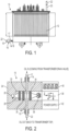
- a transformer generally indicated at 10, includes a transformer tank 12 that is filled with insulating oil to insulate components therein, such as a tap changer (not shown).
- An inlet 14 of a Furan sensor structure, generally indicated at 16 is coupled to the drain valve 18 of the tank 12 via an oil duct 17.
- An outlet 19 of the sensor structure 16 communicates with a fill port 20 at the top of the tank 12 via a second oil duct 22. It is noted that that in FIG. 1 , only portions of the second oil duct 22 are shown.
- transformer oil from the tank 12 exits the drain valve, passes through the sensor structure 16, and then is directed back into the tank via port 20.
- the non-invasive sensor structure 16 includes a single sensor housing 24 that contains an ultraviolet (UV) light source 26, a collimating lens 28, a low band (e.g., 225-330 nm) filter 30, a transparent optical (e.g., glass) window 32 allowing the UV light to pass there-through and disposed between the inlet 14 and the outlet 19, a condensing lens 34 and a UV photodiode or light detector 36.
- An operational amplifier (OPAMP) 38 amplifies the output of the light detector 36.
- the output of the OPAMP 38 is displayed on a display 40.
- the display 40 can be analog or digital or even an audible signal can indicate an alarm condition.
- a universal power supply 42 preferably disposed within the housing 24, provides power to the sensor structure 16.
- the OPAMP 38, display 40, and the power supply 42 are also preferably disposed in the housing 24.
- the sensor structure 16' is of the invasive type with a sensor head 45 disposed within the tank 12, and with the housing 24' being disposed outside of the tank 12.
- the housing 24' contains the ultraviolet (UV) light source 26, a collimating lens 46, a condensing lens 48, a fiber optics connector 49 coupled to a first fiber optics cable 50.
- the other end of the cable 50 has a fiber optics connector 52 within the tank 12 so that the UV light may be transmitted to the window 32 inside of the tank 12.
- the sensor head 46 also includes the collimating lens 28, the low band (225-330 nm) filter 30, the window 32, and condensing lens 34.
- Another fiber optics connector 54 is coupled to a second fiber optics cable 56.
- the other end of the cable 56 includes a fiber optics connector 57 so that UV light passing through the window 32 can be transmitted back to the housing 24' to be received by the light detector 36.
- a collimating lens 58 and a condensing lens 60 are provided in front of the UV light detector 36 within the housing 24'.
- the operational amplifier (OPAMP) 38 amplifies the output of the light detector 36.
- the output of the OPAMP 38 is displayed on a digital display 40.
- the display 40 or an audible signal can indicate an alarm condition.
- a universal power supply 42 preferably disposed within the housing 24', provides power to the sensor structure 16'.
- the UV light source 26 can be a light emitting diode or a laser.
- the sensor head 45 can be incorporated into a tube or probe that can be inserted, in a sealed manner, into the drain valve opening in the tank 12 or any other process pipe of the tank 12 so as to be exposed to transformer oil in the tank 12.
- oil 44 in the tank 12 surrounds the optical (e.g., glass) window 32.
- the UV light source 26 emits UV light that passes through the fiber optics cable 50, through lens 28 and filter 30 and through the glass window 32.
- the fiber optics cable 56 receives the UV light at connector 54, with the photo detector 26 receiving the UV light within the housing 24'.
- the Furans will absorb UV light, thus creating a difference in UV light received by the photo light 36 when compared to the UV light received by the light detector 36 when the oil has no Furans therein.
- the level of Furnas can be displayed on display 40 of FIG. 3 .
- Furans although very important to assess Kraft paper aging in power transformers, are difficult to quantitatively correlate to the actual aging of the solid insulation.
- Several studies have been carried out in many parts of the world trying to find a good ad universal correlation between Furans and the actual status of the solid insulation. However, such a correlation has yet to be achieved.
- Researcher and transformer experts agree, however, that the change in Furans level may bring better information than the level itself.
- Significant changes in the level of Furans may be related to accelerated aging of the transformer or initiation of some faulty condition, particularly due to thermal aspects, but also due to chemical aspects to the insulation, as from, O 2 , acids and moisture.
- using the sensor structure 16, 16' to monitor the change in Furan level online may give transformer users a better insight into what is actually occurring with the insulation.
Landscapes
- Physics & Mathematics (AREA)
- Spectroscopy & Molecular Physics (AREA)
- Biochemistry (AREA)
- Life Sciences & Earth Sciences (AREA)
- Chemical & Material Sciences (AREA)
- Analytical Chemistry (AREA)
- Health & Medical Sciences (AREA)
- General Health & Medical Sciences (AREA)
- General Physics & Mathematics (AREA)
- Immunology (AREA)
- Pathology (AREA)
- Investigating Or Analysing Materials By Optical Means (AREA)
- Photometry And Measurement Of Optical Pulse Characteristics (AREA)
- Housings And Mounting Of Transformers (AREA)
- Testing Relating To Insulation (AREA)
Claims (20)
- Sensorstruktur (16, 16') zur Online-Überwachung des Gehalts an Furanen in Öl (44) eines Transformatorbehälters (12), wobei die Sensorstruktur (16, 16') dadurch gekennzeichnet ist, dass sie aufweist:eine UV-Lichtquelle (26),ein Filter (30), das nur UV-Licht eines bestimmten Wellenlängenbereichs durch das Filter (30) durchlässt,ein transparentes Fenster (32), das so angeordnet ist, dass das gefilterte UV-Licht durch dieses durchtritt,wobei das Fenster (32) einen Durchgang aufweist, durch den das Öl (44) fließen kann,wobei UV-Licht (33) durch eine erste Seite des Fensters (32) durchgelassen wird, durch den Durchgang wandert und auf einer zweiten Seite des Fensters (32) austritt, undeinen UV-Lichtdetektor (36), der zum Empfangen von UV-Licht ausgelegt ist, das durch das Fenster (32) durchtritt,wobei, wenn die Sensorstruktur (16, 16') in Bezug auf den Transformatorbehälter (12), der online ist, so montiert ist, dass das Fenster (32) dem Öl ausgesetzt ist und die Furane im Öl überwacht werden, die Furane UV-Licht absorbieren, wodurch ein Unterschied im UV-Licht, das vom UV-Lichtdetektor (36) empfangen wird, im Vergleich zu dem UV-Licht erzeugt wird, das vom UV-Lichtdetektor (36) empfangen wird, wenn das überwachte Öl keine Furane darin aufweist, undwobei der UV-Lichtdetektor (36) so ausgelegt ist, dass er ein Ausgangssignal bereitstellt, das im Wesentlichen proportional zu einer Gesamtmenge der Furane im überwachten Öl ist.
- Sensorstruktur nach Anspruch 1, wobei das Filter (30) zum Filtern von UV-Licht auf einen Bereich von 225 bis 330 nm ausgelegt ist.
- Sensorstruktur nach Anspruch 1, wobei die UV-Lichtquelle (26) ein Laser ist.
- Sensorstruktur nach Anspruch 1, wobei die UV-Lichtquelle (26) eine Leuchtdiode ist.
- Sensorstruktur nach Anspruch 1, wobei das Ausgangssignal proportional zur Menge an 2-Furfuraldehyd und Gesamtfuranen ist.
- Sensorstruktur nach Anspruch 1, ferner aufweisend eine Kollimationslinse (28), die zwischen der UV-Lichtquelle (26) und dem Filter (30) angeordnet ist, und eine Kondensorlinse (34), die zwischen dem Filter (30) und dem UV-Lichtdetektor (36) angeordnet ist.
- Sensorstruktur nach Anspruch 6, ferner aufweisend einen Verstärker (38), der zum Verstärken des Ausgangssignals aus dem UV-Lichtdetektor (36) ausgelegt ist.
- Sensorstruktur nach Anspruch 7, ferner aufweisend eine Leistungsversorgung (42) zum Speisen der Sensorstruktur (16, 16') und eine digitale Anzeige (40) zum Anzeigen des Furangehalts im überwachten Öl.
- Sensorstruktur nach Anspruch 8, wobei die Leistungsversorgung (42), der Verstärker (38), die Anzeige (40), der UV-Lichtdetektor (36), die Linsen (28, 34), das Filter (30), das Fenster (32) und die UV-Lichtquelle (26) alle in einem einzigen Gehäuse (24) angeordnet sind.
- Sensorstruktur nach Anspruch 9 in Kombination mit dem Transformatorbehälter (12), wobei der Behälter (12) ein Ablassventil (18) aufweist, das Gehäuse (24) einen Einlass (14) und einen Auslass (19) aufweist, wobei das Fenster (32) dazwischen angeordnet ist, der Einlass (14) mit dem Ablassventil (18) gekoppelt ist, um Öl vom Behälter (12) zu empfangen, und der Auslass (19) mit dem Behälter (12) gekoppelt ist, um das Öl zum Behälter (12) zurückzuführen.
- Sensorstruktur nach Anspruch 1, wobei das Filter (30) und das Fenster (32) Teil eines Sensorkopfs (45) sind, der Sensorkopf (45) ferner eine Kollimationslinse (28) zwischen der UV-Lichtquelle (26) und dem Filter (30) und eine Kondensorlinse (34) zwischen dem Filter (30) und dem Lichtdetektor (36) aufweist, wobei der Sensorkopf (45) dazu ausgelegt ist, innerhalb des Behälters (12) bereitgestellt zu werden, wobei die UV-Lichtquelle (26) und der UV-Lichtdetektor (36) dazu ausgelegt sind, außerhalb des Behälters (12) bereitgestellt zu werden.
- Sensorstruktur nach Anspruch 1, ferner aufweisend ein erstes Glasfaserkabel (50), das sich zwischen der Kollimationslinse (28) und der UV-Lichtquelle (26) erstreckt, und ein zweites Glasfaserkabel (56), das sich zwischen der Kondensorlinse (34) und dem UV-Lichtdetektor (36) erstreckt.
- Sensorstruktur nach Anspruch 12, ferner aufweisend eine Kollimationslinse (28) und eine Kondensorlinse (34) zwischen der UV-Lichtquelle (26) und dem ersten Glasfaserkabel (50) und eine Kollimationslinse (28) und eine Kondensorlinse (34) zwischen dem zweiten Glasfaserkabel (56) und dem UV-Lichtdetektor (36).
- Sensorstruktur nach Anspruch 13, ferner aufweisend einen Verstärker (38), der zum Verstärken des Ausgangssignals aus dem UV-Lichtdetektor (36) ausgelegt ist.
- Sensorstruktur nach Anspruch 14, ferner aufweisend eine Leistungsversorgung zum Speisen der Sensorstruktur und eine digitale Anzeige zum Anzeigen eines Gehalts an überwachten Furanen.
- Sensorstruktur nach Anspruch 14, wobei die Leistungsversorgung (42), der Verstärker (38), die Anzeige (40), der UV-Lichtdetektor (36) und die UV-Lichtquelle (26) alle in einem einzigen Gehäuse (24') angeordnet sind, das vom Sensorkopf (24) getrennt ist.
- Sensorstruktur nach Anspruch 1 in Kombination mit dem Transformatorbehälter (12), wobei der Sensorkopf (45) innerhalb des Behälters (12) angeordnet ist, sodass das Fenster (32) dem Öl ausgesetzt ist, und das einzige Gehäuse (24') außerhalb des Behälters (12) angeordnet ist, wobei das erste Glasfaserkabel (50) das UV-Licht zum Fenster (32) überträgt und das zweite Glasfaserkabel (56) das UV-Licht, das durch das Fenster (32) durchtritt, zum UV-Lichtdetektor (36) überträgt.
- Verfahren zur Online-Überwachung eines Gehalts an Furanen in Öl (44) eines Transformatorbehälters (12), wobei das Verfahren die folgenden Schritte umfasst:Bereitstellen einer UV-Lichtquelle (26),Filtern des UV-Lichts auf einen bestimmten Wellenbereich,Bereitstellen eines transparenten Fensters (32), das dem Öl (44) des Transformatorbehälters (12) ausgesetzt wird, wobei das Fenster (32) einen Durchgang aufweist, durch den das Öl (44) fließen kann, wobei UV-Licht (33) durch eine erste Seite des Fensters (32) durchgelassen wird, durch den Durchgang wandert und auf einer zweiten Seite des Fensters (32) austritt, wobei das gefilterte UV-Licht durch das Fenster (32) durchtritt, während der Transformator online ist, undEmpfangen des UV-Lichts, das durch das Fenster (32) durchtritt, an einem UV-Lichtdetektor (36), wobei ein Ausgangssignal des UV-Lichtdetektors (36) im Wesentlichen proportional zu einer Gesamtmenge der Furane im Öl ist, das überwacht wird.
- Verfahren nach Anspruch 18, wobei der Filterschritt ein Filtern des UV-Lichts auf einen Bereich von 225 bis 330 nm umfasst.
- Verfahren nach Anspruch 18, wobei das Ausgangssignal proportional zur Menge an 2-Furfuraldehyd und Gesamtfuranen ist.
Applications Claiming Priority (2)
| Application Number | Priority Date | Filing Date | Title |
|---|---|---|---|
| US201161549793P | 2011-10-21 | 2011-10-21 | |
| PCT/US2012/059417 WO2013059032A1 (en) | 2011-10-21 | 2012-10-10 | Sensor structure for online monitoring of furans in power transformers |
Publications (2)
| Publication Number | Publication Date |
|---|---|
| EP2769205A1 EP2769205A1 (de) | 2014-08-27 |
| EP2769205B1 true EP2769205B1 (de) | 2024-08-14 |
Family
ID=47146682
Family Applications (1)
| Application Number | Title | Priority Date | Filing Date |
|---|---|---|---|
| EP12783739.1A Active EP2769205B1 (de) | 2011-10-21 | 2012-10-10 | Sensorstruktur zur online-überwachung von furanen in netztransformatoren |
Country Status (6)
| Country | Link |
|---|---|
| US (1) | US9383315B2 (de) |
| EP (1) | EP2769205B1 (de) |
| CN (1) | CN103930770B (de) |
| BR (1) | BR112014009396B1 (de) |
| CA (1) | CA2857124C (de) |
| WO (1) | WO2013059032A1 (de) |
Families Citing this family (4)
| Publication number | Priority date | Publication date | Assignee | Title |
|---|---|---|---|---|
| CN103996493B (zh) * | 2014-05-08 | 2016-02-10 | 昆山佑翔电子科技有限公司 | 基于油浊度监测的预报警变压器 |
| WO2018022046A1 (en) * | 2016-07-27 | 2018-02-01 | Hewlett-Packard Development Company, L.P. | Providing powder in three-dimensional (3d) additive manufacturing |
| JP6954405B2 (ja) * | 2019-05-16 | 2021-10-27 | ダイキン工業株式会社 | 液体センサ及び油圧ユニット |
| CN120948399A (zh) * | 2025-09-30 | 2025-11-14 | 华能酒泉发电有限公司 | 一种基于红外吸收法的绝缘油中糠醛含量的测定仪 |
Citations (1)
| Publication number | Priority date | Publication date | Assignee | Title |
|---|---|---|---|---|
| US20080304048A1 (en) * | 2005-11-29 | 2008-12-11 | Ge Healthcare Bio-Sciences Ab | Methods and Apparatus For Measuring the Concentration of a Substance in a Solution |
Family Cites Families (10)
| Publication number | Priority date | Publication date | Assignee | Title |
|---|---|---|---|---|
| US3308712A (en) * | 1963-11-06 | 1967-03-14 | Ibm | Transducer for spectrum analysis applicable to closed loop control |
| US3925220A (en) * | 1972-08-15 | 1975-12-09 | Sun Oil Co Pennsylvania | Process of comprising solvent extraction of a blended oil |
| CA2054616A1 (en) * | 1991-10-31 | 1993-05-01 | John Sabau | Method of determining stability of insulating oil |
| TW343281B (en) * | 1996-06-28 | 1998-10-21 | Hitachi Ltd | Method and apparatus for diagnosing degradation of an electric machine |
| SG99872A1 (en) * | 1999-10-26 | 2003-11-27 | Mitsubishi Heavy Ind Ltd | Method and apparatus for laser analysis of dioxins |
| CN1445527A (zh) * | 2003-04-29 | 2003-10-01 | 上海交通大学 | 变压器油带电量测定用光纤传感器 |
| CN100351624C (zh) * | 2005-01-13 | 2007-11-28 | 上海众毅工业控制技术有限公司 | 基于喇曼技术的电力变压器油中溶解气体分析装置 |
| CN101762680A (zh) * | 2008-12-24 | 2010-06-30 | 上海宝钢工业检测公司 | 大型变压器油寿命的检测方法 |
| CN102000448B (zh) * | 2009-09-02 | 2013-07-17 | 湖北省电力公司电力科学研究院 | 变压器油中呋喃系列化合物的快速高效萃取方法及用于萃取的比色管振荡托架 |
| CN101887094A (zh) * | 2010-06-30 | 2010-11-17 | 河南省电力公司济源供电公司 | 变压器固体绝缘老化程度的判断方法 |
-
2012
- 2012-10-10 EP EP12783739.1A patent/EP2769205B1/de active Active
- 2012-10-10 US US14/351,890 patent/US9383315B2/en active Active
- 2012-10-10 CN CN201280051513.4A patent/CN103930770B/zh active Active
- 2012-10-10 CA CA2857124A patent/CA2857124C/en active Active
- 2012-10-10 BR BR112014009396-2A patent/BR112014009396B1/pt active IP Right Grant
- 2012-10-10 WO PCT/US2012/059417 patent/WO2013059032A1/en not_active Ceased
Patent Citations (1)
| Publication number | Priority date | Publication date | Assignee | Title |
|---|---|---|---|---|
| US20080304048A1 (en) * | 2005-11-29 | 2008-12-11 | Ge Healthcare Bio-Sciences Ab | Methods and Apparatus For Measuring the Concentration of a Substance in a Solution |
Non-Patent Citations (1)
| Title |
|---|
| ANONYMOUS: "Furfural - Wikipedia", 7 June 2019 (2019-06-07), XP055594931, Retrieved from the Internet <URL:https://en.wikipedia.org/wiki/Furfural> [retrieved on 20190607] * |
Also Published As
| Publication number | Publication date |
|---|---|
| WO2013059032A1 (en) | 2013-04-25 |
| EP2769205A1 (de) | 2014-08-27 |
| BR112014009396A2 (pt) | 2017-04-18 |
| US20140291536A1 (en) | 2014-10-02 |
| CA2857124A1 (en) | 2013-04-25 |
| US9383315B2 (en) | 2016-07-05 |
| CA2857124C (en) | 2019-08-13 |
| CN103930770B (zh) | 2017-02-22 |
| BR112014009396B1 (pt) | 2021-11-09 |
| CN103930770A (zh) | 2014-07-16 |
Similar Documents
| Publication | Publication Date | Title |
|---|---|---|
| US7385692B1 (en) | Method and system for fiber optic determination of gas concentrations in liquid receptacles | |
| JP5097782B2 (ja) | 油圧作動油内の化学汚染を監視するオンラインセンサ | |
| CA2640102C (en) | Method and apparatus for calibrated downhole spectral analysis of fluids | |
| EP2769205B1 (de) | Sensorstruktur zur online-überwachung von furanen in netztransformatoren | |
| US11237089B2 (en) | Method and system for particle characterization and identification | |
| RU2645899C2 (ru) | Оптический химический анализатор и датчик глубины жидкости | |
| US20040056197A1 (en) | Optical steam quality measurement system and method | |
| FI95322C (fi) | Spektroskooppinen mittausanturi väliaineiden analysointiin | |
| BRPI0806880A2 (pt) | Analisador químico óptico, e, método para medir concentrações químicas em uma corrente contínua ou processo em batelada | |
| CN104807765B (zh) | 高灵敏度光谱吸收衰减振荡腔的变压器油中气体检测装置 | |
| CN109239008B (zh) | 一种基于微纳光纤倏逝场的油浸式变压器故障检测装置 | |
| US20100253933A1 (en) | In-line mercury detector for hydrocarbon and natural gas | |
| CN110542839A (zh) | 用于sf6气体绝缘设备的全光学绝缘故障监测系统 | |
| JP2019522195A (ja) | 気相媒質の品質を監視するための方法及び装置 | |
| CN109087719A (zh) | 一种安全壳内主蒸汽管道泄漏监测系统 | |
| JPH05240790A (ja) | 液流中の溶質を監視するセンサ | |
| CN100351624C (zh) | 基于喇曼技术的电力变压器油中溶解气体分析装置 | |
| US10996201B2 (en) | Photoacoustic measurement systems and methods using the photoacoustic effect to measure emission intensities, gas concentrations, and distances | |
| US11747200B2 (en) | Optical process sensor, measuring head, measuring system comprising the two and method for calibration and/or validation | |
| CN107340275B (zh) | 一种水质在线检测系统 | |
| CN107337253B (zh) | 一种紫外线杀菌装置 | |
| JP2013053949A (ja) | アセチレンガスセンサ | |
| KR20200082725A (ko) | 광섬유 센서 | |
| EP3748337A1 (de) | Sonde zur gleichzeitigen analyse mit verschiedenen spektroskopischen techniken und entsprechendes verfahren | |
| Jin et al. | Optical fiber gas sensor development and application |
Legal Events
| Date | Code | Title | Description |
|---|---|---|---|
| PUAI | Public reference made under article 153(3) epc to a published international application that has entered the european phase |
Free format text: ORIGINAL CODE: 0009012 |
|
| 17P | Request for examination filed |
Effective date: 20140506 |
|
| AK | Designated contracting states |
Kind code of ref document: A1 Designated state(s): AL AT BE BG CH CY CZ DE DK EE ES FI FR GB GR HR HU IE IS IT LI LT LU LV MC MK MT NL NO PL PT RO RS SE SI SK SM TR |
|
| RAP1 | Party data changed (applicant data changed or rights of an application transferred) |
Owner name: ABB TECHNOLOGY AG |
|
| DAX | Request for extension of the european patent (deleted) | ||
| RAP1 | Party data changed (applicant data changed or rights of an application transferred) |
Owner name: ABB SCHWEIZ AG |
|
| STAA | Information on the status of an ep patent application or granted ep patent |
Free format text: STATUS: EXAMINATION IS IN PROGRESS |
|
| 17Q | First examination report despatched |
Effective date: 20190617 |
|
| RAP1 | Party data changed (applicant data changed or rights of an application transferred) |
Owner name: ABB POWER GRIDS SWITZERLAND AG |
|
| RAP3 | Party data changed (applicant data changed or rights of an application transferred) |
Owner name: HITACHI ENERGY SWITZERLAND AG |
|
| P01 | Opt-out of the competence of the unified patent court (upc) registered |
Effective date: 20230527 |
|
| RAP1 | Party data changed (applicant data changed or rights of an application transferred) |
Owner name: HITACHI ENERGY LTD |
|
| GRAP | Despatch of communication of intention to grant a patent |
Free format text: ORIGINAL CODE: EPIDOSNIGR1 |
|
| STAA | Information on the status of an ep patent application or granted ep patent |
Free format text: STATUS: GRANT OF PATENT IS INTENDED |
|
| RIC1 | Information provided on ipc code assigned before grant |
Ipc: G01N 21/33 20060101ALI20240229BHEP Ipc: G01N 21/85 20060101AFI20240229BHEP |
|
| INTG | Intention to grant announced |
Effective date: 20240321 |
|
| GRAS | Grant fee paid |
Free format text: ORIGINAL CODE: EPIDOSNIGR3 |
|
| GRAA | (expected) grant |
Free format text: ORIGINAL CODE: 0009210 |
|
| STAA | Information on the status of an ep patent application or granted ep patent |
Free format text: STATUS: THE PATENT HAS BEEN GRANTED |
|
| AK | Designated contracting states |
Kind code of ref document: B1 Designated state(s): AL AT BE BG CH CY CZ DE DK EE ES FI FR GB GR HR HU IE IS IT LI LT LU LV MC MK MT NL NO PL PT RO RS SE SI SK SM TR |
|
| REG | Reference to a national code |
Ref country code: GB Ref legal event code: FG4D |
|
| RIN1 | Information on inventor provided before grant (corrected) |
Inventor name: WUEEST, ROBERT Inventor name: KOUZMINE, OLEG Inventor name: CHEIM, LUIZ, V. |
|
| REG | Reference to a national code |
Ref country code: CH Ref legal event code: EP |
|
| REG | Reference to a national code |
Ref country code: DE Ref legal event code: R096 Ref document number: 602012081003 Country of ref document: DE |
|
| REG | Reference to a national code |
Ref country code: IE Ref legal event code: FG4D |
|
| REG | Reference to a national code |
Ref country code: LT Ref legal event code: MG9D |
|
| PG25 | Lapsed in a contracting state [announced via postgrant information from national office to epo] |
Ref country code: NO Free format text: LAPSE BECAUSE OF FAILURE TO SUBMIT A TRANSLATION OF THE DESCRIPTION OR TO PAY THE FEE WITHIN THE PRESCRIBED TIME-LIMIT Effective date: 20241114 |
|
| REG | Reference to a national code |
Ref country code: AT Ref legal event code: MK05 Ref document number: 1713711 Country of ref document: AT Kind code of ref document: T Effective date: 20240814 |
|
| PG25 | Lapsed in a contracting state [announced via postgrant information from national office to epo] |
Ref country code: NL Free format text: LAPSE BECAUSE OF FAILURE TO SUBMIT A TRANSLATION OF THE DESCRIPTION OR TO PAY THE FEE WITHIN THE PRESCRIBED TIME-LIMIT Effective date: 20240814 Ref country code: FI Free format text: LAPSE BECAUSE OF FAILURE TO SUBMIT A TRANSLATION OF THE DESCRIPTION OR TO PAY THE FEE WITHIN THE PRESCRIBED TIME-LIMIT Effective date: 20240814 Ref country code: PT Free format text: LAPSE BECAUSE OF FAILURE TO SUBMIT A TRANSLATION OF THE DESCRIPTION OR TO PAY THE FEE WITHIN THE PRESCRIBED TIME-LIMIT Effective date: 20241216 Ref country code: PL Free format text: LAPSE BECAUSE OF FAILURE TO SUBMIT A TRANSLATION OF THE DESCRIPTION OR TO PAY THE FEE WITHIN THE PRESCRIBED TIME-LIMIT Effective date: 20240814 Ref country code: GR Free format text: LAPSE BECAUSE OF FAILURE TO SUBMIT A TRANSLATION OF THE DESCRIPTION OR TO PAY THE FEE WITHIN THE PRESCRIBED TIME-LIMIT Effective date: 20241115 |
|
| PG25 | Lapsed in a contracting state [announced via postgrant information from national office to epo] |
Ref country code: BG Free format text: LAPSE BECAUSE OF FAILURE TO SUBMIT A TRANSLATION OF THE DESCRIPTION OR TO PAY THE FEE WITHIN THE PRESCRIBED TIME-LIMIT Effective date: 20240814 |
|
| PG25 | Lapsed in a contracting state [announced via postgrant information from national office to epo] |
Ref country code: LV Free format text: LAPSE BECAUSE OF FAILURE TO SUBMIT A TRANSLATION OF THE DESCRIPTION OR TO PAY THE FEE WITHIN THE PRESCRIBED TIME-LIMIT Effective date: 20240814 |
|
| PG25 | Lapsed in a contracting state [announced via postgrant information from national office to epo] |
Ref country code: AT Free format text: LAPSE BECAUSE OF FAILURE TO SUBMIT A TRANSLATION OF THE DESCRIPTION OR TO PAY THE FEE WITHIN THE PRESCRIBED TIME-LIMIT Effective date: 20240814 Ref country code: IS Free format text: LAPSE BECAUSE OF FAILURE TO SUBMIT A TRANSLATION OF THE DESCRIPTION OR TO PAY THE FEE WITHIN THE PRESCRIBED TIME-LIMIT Effective date: 20241214 |
|
| PG25 | Lapsed in a contracting state [announced via postgrant information from national office to epo] |
Ref country code: HR Free format text: LAPSE BECAUSE OF FAILURE TO SUBMIT A TRANSLATION OF THE DESCRIPTION OR TO PAY THE FEE WITHIN THE PRESCRIBED TIME-LIMIT Effective date: 20240814 |
|
| PG25 | Lapsed in a contracting state [announced via postgrant information from national office to epo] |
Ref country code: ES Free format text: LAPSE BECAUSE OF FAILURE TO SUBMIT A TRANSLATION OF THE DESCRIPTION OR TO PAY THE FEE WITHIN THE PRESCRIBED TIME-LIMIT Effective date: 20240814 Ref country code: RS Free format text: LAPSE BECAUSE OF FAILURE TO SUBMIT A TRANSLATION OF THE DESCRIPTION OR TO PAY THE FEE WITHIN THE PRESCRIBED TIME-LIMIT Effective date: 20241114 |
|
| PG25 | Lapsed in a contracting state [announced via postgrant information from national office to epo] |
Ref country code: RS Free format text: LAPSE BECAUSE OF FAILURE TO SUBMIT A TRANSLATION OF THE DESCRIPTION OR TO PAY THE FEE WITHIN THE PRESCRIBED TIME-LIMIT Effective date: 20241114 Ref country code: PT Free format text: LAPSE BECAUSE OF FAILURE TO SUBMIT A TRANSLATION OF THE DESCRIPTION OR TO PAY THE FEE WITHIN THE PRESCRIBED TIME-LIMIT Effective date: 20241216 Ref country code: PL Free format text: LAPSE BECAUSE OF FAILURE TO SUBMIT A TRANSLATION OF THE DESCRIPTION OR TO PAY THE FEE WITHIN THE PRESCRIBED TIME-LIMIT Effective date: 20240814 Ref country code: NO Free format text: LAPSE BECAUSE OF FAILURE TO SUBMIT A TRANSLATION OF THE DESCRIPTION OR TO PAY THE FEE WITHIN THE PRESCRIBED TIME-LIMIT Effective date: 20241114 Ref country code: NL Free format text: LAPSE BECAUSE OF FAILURE TO SUBMIT A TRANSLATION OF THE DESCRIPTION OR TO PAY THE FEE WITHIN THE PRESCRIBED TIME-LIMIT Effective date: 20240814 Ref country code: LV Free format text: LAPSE BECAUSE OF FAILURE TO SUBMIT A TRANSLATION OF THE DESCRIPTION OR TO PAY THE FEE WITHIN THE PRESCRIBED TIME-LIMIT Effective date: 20240814 Ref country code: IS Free format text: LAPSE BECAUSE OF FAILURE TO SUBMIT A TRANSLATION OF THE DESCRIPTION OR TO PAY THE FEE WITHIN THE PRESCRIBED TIME-LIMIT Effective date: 20241214 Ref country code: HR Free format text: LAPSE BECAUSE OF FAILURE TO SUBMIT A TRANSLATION OF THE DESCRIPTION OR TO PAY THE FEE WITHIN THE PRESCRIBED TIME-LIMIT Effective date: 20240814 Ref country code: GR Free format text: LAPSE BECAUSE OF FAILURE TO SUBMIT A TRANSLATION OF THE DESCRIPTION OR TO PAY THE FEE WITHIN THE PRESCRIBED TIME-LIMIT Effective date: 20241115 Ref country code: FI Free format text: LAPSE BECAUSE OF FAILURE TO SUBMIT A TRANSLATION OF THE DESCRIPTION OR TO PAY THE FEE WITHIN THE PRESCRIBED TIME-LIMIT Effective date: 20240814 Ref country code: ES Free format text: LAPSE BECAUSE OF FAILURE TO SUBMIT A TRANSLATION OF THE DESCRIPTION OR TO PAY THE FEE WITHIN THE PRESCRIBED TIME-LIMIT Effective date: 20240814 Ref country code: BG Free format text: LAPSE BECAUSE OF FAILURE TO SUBMIT A TRANSLATION OF THE DESCRIPTION OR TO PAY THE FEE WITHIN THE PRESCRIBED TIME-LIMIT Effective date: 20240814 Ref country code: AT Free format text: LAPSE BECAUSE OF FAILURE TO SUBMIT A TRANSLATION OF THE DESCRIPTION OR TO PAY THE FEE WITHIN THE PRESCRIBED TIME-LIMIT Effective date: 20240814 |
|
| PG25 | Lapsed in a contracting state [announced via postgrant information from national office to epo] |
Ref country code: SM Free format text: LAPSE BECAUSE OF FAILURE TO SUBMIT A TRANSLATION OF THE DESCRIPTION OR TO PAY THE FEE WITHIN THE PRESCRIBED TIME-LIMIT Effective date: 20240814 Ref country code: DK Free format text: LAPSE BECAUSE OF FAILURE TO SUBMIT A TRANSLATION OF THE DESCRIPTION OR TO PAY THE FEE WITHIN THE PRESCRIBED TIME-LIMIT Effective date: 20240814 Ref country code: RO Free format text: LAPSE BECAUSE OF FAILURE TO SUBMIT A TRANSLATION OF THE DESCRIPTION OR TO PAY THE FEE WITHIN THE PRESCRIBED TIME-LIMIT Effective date: 20240814 |
|
| PG25 | Lapsed in a contracting state [announced via postgrant information from national office to epo] |
Ref country code: EE Free format text: LAPSE BECAUSE OF FAILURE TO SUBMIT A TRANSLATION OF THE DESCRIPTION OR TO PAY THE FEE WITHIN THE PRESCRIBED TIME-LIMIT Effective date: 20240814 |
|
| PG25 | Lapsed in a contracting state [announced via postgrant information from national office to epo] |
Ref country code: CZ Free format text: LAPSE BECAUSE OF FAILURE TO SUBMIT A TRANSLATION OF THE DESCRIPTION OR TO PAY THE FEE WITHIN THE PRESCRIBED TIME-LIMIT Effective date: 20240814 |
|
| PG25 | Lapsed in a contracting state [announced via postgrant information from national office to epo] |
Ref country code: IT Free format text: LAPSE BECAUSE OF FAILURE TO SUBMIT A TRANSLATION OF THE DESCRIPTION OR TO PAY THE FEE WITHIN THE PRESCRIBED TIME-LIMIT Effective date: 20240814 Ref country code: SK Free format text: LAPSE BECAUSE OF FAILURE TO SUBMIT A TRANSLATION OF THE DESCRIPTION OR TO PAY THE FEE WITHIN THE PRESCRIBED TIME-LIMIT Effective date: 20240814 |
|
| REG | Reference to a national code |
Ref country code: DE Ref legal event code: R097 Ref document number: 602012081003 Country of ref document: DE |
|
| REG | Reference to a national code |
Ref country code: CH Ref legal event code: PL |
|
| PLBE | No opposition filed within time limit |
Free format text: ORIGINAL CODE: 0009261 |
|
| STAA | Information on the status of an ep patent application or granted ep patent |
Free format text: STATUS: NO OPPOSITION FILED WITHIN TIME LIMIT |
|
| PG25 | Lapsed in a contracting state [announced via postgrant information from national office to epo] |
Ref country code: MC Free format text: LAPSE BECAUSE OF FAILURE TO SUBMIT A TRANSLATION OF THE DESCRIPTION OR TO PAY THE FEE WITHIN THE PRESCRIBED TIME-LIMIT Effective date: 20240814 |
|
| PG25 | Lapsed in a contracting state [announced via postgrant information from national office to epo] |
Ref country code: LU Free format text: LAPSE BECAUSE OF NON-PAYMENT OF DUE FEES Effective date: 20241010 Ref country code: BE Free format text: LAPSE BECAUSE OF NON-PAYMENT OF DUE FEES Effective date: 20241031 |
|
| 26N | No opposition filed |
Effective date: 20250515 |
|
| PG25 | Lapsed in a contracting state [announced via postgrant information from national office to epo] |
Ref country code: CH Free format text: LAPSE BECAUSE OF NON-PAYMENT OF DUE FEES Effective date: 20241031 |
|
| REG | Reference to a national code |
Ref country code: BE Ref legal event code: MM Effective date: 20241031 |
|
| PG25 | Lapsed in a contracting state [announced via postgrant information from national office to epo] |
Ref country code: SE Free format text: LAPSE BECAUSE OF FAILURE TO SUBMIT A TRANSLATION OF THE DESCRIPTION OR TO PAY THE FEE WITHIN THE PRESCRIBED TIME-LIMIT Effective date: 20240814 |
|
| PG25 | Lapsed in a contracting state [announced via postgrant information from national office to epo] |
Ref country code: IE Free format text: LAPSE BECAUSE OF NON-PAYMENT OF DUE FEES Effective date: 20241010 |
|
| PGFP | Annual fee paid to national office [announced via postgrant information from national office to epo] |
Ref country code: DE Payment date: 20251021 Year of fee payment: 14 |
|
| PGFP | Annual fee paid to national office [announced via postgrant information from national office to epo] |
Ref country code: GB Payment date: 20251022 Year of fee payment: 14 |
|
| PGFP | Annual fee paid to national office [announced via postgrant information from national office to epo] |
Ref country code: FR Payment date: 20251030 Year of fee payment: 14 |
|
| PG25 | Lapsed in a contracting state [announced via postgrant information from national office to epo] |
Ref country code: CY Free format text: LAPSE BECAUSE OF FAILURE TO SUBMIT A TRANSLATION OF THE DESCRIPTION OR TO PAY THE FEE WITHIN THE PRESCRIBED TIME-LIMIT; INVALID AB INITIO Effective date: 20121010 |
|
| PG25 | Lapsed in a contracting state [announced via postgrant information from national office to epo] |
Ref country code: HU Free format text: LAPSE BECAUSE OF FAILURE TO SUBMIT A TRANSLATION OF THE DESCRIPTION OR TO PAY THE FEE WITHIN THE PRESCRIBED TIME-LIMIT; INVALID AB INITIO Effective date: 20121010 |