EP3748337A1 - Sonde zur gleichzeitigen analyse mit verschiedenen spektroskopischen techniken und entsprechendes verfahren - Google Patents
Sonde zur gleichzeitigen analyse mit verschiedenen spektroskopischen techniken und entsprechendes verfahren Download PDFInfo
- Publication number
- EP3748337A1 EP3748337A1 EP19178822.3A EP19178822A EP3748337A1 EP 3748337 A1 EP3748337 A1 EP 3748337A1 EP 19178822 A EP19178822 A EP 19178822A EP 3748337 A1 EP3748337 A1 EP 3748337A1
- Authority
- EP
- European Patent Office
- Prior art keywords
- probe
- optical
- product
- window
- spectroscopic
- Prior art date
- Legal status (The legal status is an assumption and is not a legal conclusion. Google has not performed a legal analysis and makes no representation as to the accuracy of the status listed.)
- Withdrawn
Links
- 239000000523 sample Substances 0.000 title claims abstract description 124
- 238000000034 method Methods 0.000 title claims abstract description 80
- 238000004458 analytical method Methods 0.000 title claims description 16
- 238000012306 spectroscopic technique Methods 0.000 title description 6
- 230000003287 optical effect Effects 0.000 claims abstract description 80
- 230000005855 radiation Effects 0.000 claims abstract description 40
- 230000005284 excitation Effects 0.000 claims abstract description 37
- 230000037361 pathway Effects 0.000 claims abstract description 17
- 239000000047 product Substances 0.000 claims description 47
- 230000008569 process Effects 0.000 claims description 15
- 239000000203 mixture Substances 0.000 claims description 14
- 239000000126 substance Substances 0.000 claims description 7
- 238000005259 measurement Methods 0.000 claims description 6
- 238000004886 process control Methods 0.000 claims description 6
- 238000012545 processing Methods 0.000 claims description 6
- 239000000835 fiber Substances 0.000 claims description 5
- 238000005286 illumination Methods 0.000 claims description 5
- 238000009434 installation Methods 0.000 claims description 5
- 238000004519 manufacturing process Methods 0.000 claims description 5
- 239000013307 optical fiber Substances 0.000 claims description 5
- 239000000843 powder Substances 0.000 claims description 5
- 239000008187 granular material Substances 0.000 claims description 4
- 239000013590 bulk material Substances 0.000 claims description 3
- 239000007795 chemical reaction product Substances 0.000 claims description 3
- 239000006071 cream Substances 0.000 claims description 3
- 238000010801 machine learning Methods 0.000 claims description 3
- 239000002002 slurry Substances 0.000 claims description 2
- 239000008186 active pharmaceutical agent Substances 0.000 claims 1
- 238000001069 Raman spectroscopy Methods 0.000 description 20
- 239000000463 material Substances 0.000 description 8
- 238000013461 design Methods 0.000 description 7
- 230000000712 assembly Effects 0.000 description 5
- 238000000429 assembly Methods 0.000 description 5
- 230000009286 beneficial effect Effects 0.000 description 5
- 238000001514 detection method Methods 0.000 description 5
- 230000005670 electromagnetic radiation Effects 0.000 description 5
- 238000005516 engineering process Methods 0.000 description 5
- 230000000670 limiting effect Effects 0.000 description 5
- 238000004497 NIR spectroscopy Methods 0.000 description 4
- 238000010438 heat treatment Methods 0.000 description 4
- 238000004611 spectroscopical analysis Methods 0.000 description 4
- 230000000694 effects Effects 0.000 description 3
- 239000012530 fluid Substances 0.000 description 3
- 238000010191 image analysis Methods 0.000 description 3
- 238000011835 investigation Methods 0.000 description 3
- 238000005375 photometry Methods 0.000 description 3
- 238000005204 segregation Methods 0.000 description 3
- 238000005102 attenuated total reflection Methods 0.000 description 2
- 230000006399 behavior Effects 0.000 description 2
- 230000002452 interceptive effect Effects 0.000 description 2
- 238000002095 near-infrared Raman spectroscopy Methods 0.000 description 2
- 238000001228 spectrum Methods 0.000 description 2
- 238000003860 storage Methods 0.000 description 2
- 101001121408 Homo sapiens L-amino-acid oxidase Proteins 0.000 description 1
- 102100026388 L-amino-acid oxidase Human genes 0.000 description 1
- 230000009471 action Effects 0.000 description 1
- 239000006117 anti-reflective coating Substances 0.000 description 1
- 238000013459 approach Methods 0.000 description 1
- 230000004888 barrier function Effects 0.000 description 1
- 230000008859 change Effects 0.000 description 1
- 238000000576 coating method Methods 0.000 description 1
- 238000010276 construction Methods 0.000 description 1
- 238000010924 continuous production Methods 0.000 description 1
- 239000010987 cubic zirconia Substances 0.000 description 1
- 229910003460 diamond Inorganic materials 0.000 description 1
- 239000010432 diamond Substances 0.000 description 1
- 230000006870 function Effects 0.000 description 1
- 230000002401 inhibitory effect Effects 0.000 description 1
- 238000003780 insertion Methods 0.000 description 1
- 230000037431 insertion Effects 0.000 description 1
- 239000012263 liquid product Substances 0.000 description 1
- 238000004476 mid-IR spectroscopy Methods 0.000 description 1
- 238000002156 mixing Methods 0.000 description 1
- 238000012986 modification Methods 0.000 description 1
- 230000004048 modification Effects 0.000 description 1
- 239000003607 modifier Substances 0.000 description 1
- 239000002245 particle Substances 0.000 description 1
- 230000035515 penetration Effects 0.000 description 1
- 238000000275 quality assurance Methods 0.000 description 1
- 238000005070 sampling Methods 0.000 description 1
- 229910052594 sapphire Inorganic materials 0.000 description 1
- 239000010980 sapphire Substances 0.000 description 1
- 239000012265 solid product Substances 0.000 description 1
- 230000003595 spectral effect Effects 0.000 description 1
- 238000002798 spectrophotometry method Methods 0.000 description 1
- 230000003068 static effect Effects 0.000 description 1
- 230000002123 temporal effect Effects 0.000 description 1
- 238000012360 testing method Methods 0.000 description 1
- 238000000870 ultraviolet spectroscopy Methods 0.000 description 1
- 239000011800 void material Substances 0.000 description 1
Images


Classifications
-
- G—PHYSICS
- G01—MEASURING; TESTING
- G01N—INVESTIGATING OR ANALYSING MATERIALS BY DETERMINING THEIR CHEMICAL OR PHYSICAL PROPERTIES
- G01N21/00—Investigating or analysing materials by the use of optical means, i.e. using sub-millimetre waves, infrared, visible or ultraviolet light
- G01N21/17—Systems in which incident light is modified in accordance with the properties of the material investigated
- G01N21/25—Colour; Spectral properties, i.e. comparison of effect of material on the light at two or more different wavelengths or wavelength bands
- G01N21/31—Investigating relative effect of material at wavelengths characteristic of specific elements or molecules, e.g. atomic absorption spectrometry
- G01N21/35—Investigating relative effect of material at wavelengths characteristic of specific elements or molecules, e.g. atomic absorption spectrometry using infrared light
- G01N21/359—Investigating relative effect of material at wavelengths characteristic of specific elements or molecules, e.g. atomic absorption spectrometry using infrared light using near infrared light
-
- G—PHYSICS
- G01—MEASURING; TESTING
- G01N—INVESTIGATING OR ANALYSING MATERIALS BY DETERMINING THEIR CHEMICAL OR PHYSICAL PROPERTIES
- G01N21/00—Investigating or analysing materials by the use of optical means, i.e. using sub-millimetre waves, infrared, visible or ultraviolet light
- G01N21/62—Systems in which the material investigated is excited whereby it emits light or causes a change in wavelength of the incident light
- G01N21/63—Systems in which the material investigated is excited whereby it emits light or causes a change in wavelength of the incident light optically excited
- G01N21/65—Raman scattering
-
- G—PHYSICS
- G01—MEASURING; TESTING
- G01N—INVESTIGATING OR ANALYSING MATERIALS BY DETERMINING THEIR CHEMICAL OR PHYSICAL PROPERTIES
- G01N21/00—Investigating or analysing materials by the use of optical means, i.e. using sub-millimetre waves, infrared, visible or ultraviolet light
- G01N21/84—Systems specially adapted for particular applications
- G01N21/85—Investigating moving fluids or granular solids
-
- G—PHYSICS
- G01—MEASURING; TESTING
- G01N—INVESTIGATING OR ANALYSING MATERIALS BY DETERMINING THEIR CHEMICAL OR PHYSICAL PROPERTIES
- G01N21/00—Investigating or analysing materials by the use of optical means, i.e. using sub-millimetre waves, infrared, visible or ultraviolet light
- G01N21/84—Systems specially adapted for particular applications
- G01N2021/8411—Application to online plant, process monitoring
- G01N2021/8416—Application to online plant, process monitoring and process controlling, not otherwise provided for
-
- G—PHYSICS
- G01—MEASURING; TESTING
- G01N—INVESTIGATING OR ANALYSING MATERIALS BY DETERMINING THEIR CHEMICAL OR PHYSICAL PROPERTIES
- G01N21/00—Investigating or analysing materials by the use of optical means, i.e. using sub-millimetre waves, infrared, visible or ultraviolet light
- G01N21/01—Arrangements or apparatus for facilitating the optical investigation
- G01N21/15—Preventing contamination of the components of the optical system or obstruction of the light path
-
- G—PHYSICS
- G01—MEASURING; TESTING
- G01N—INVESTIGATING OR ANALYSING MATERIALS BY DETERMINING THEIR CHEMICAL OR PHYSICAL PROPERTIES
- G01N21/00—Investigating or analysing materials by the use of optical means, i.e. using sub-millimetre waves, infrared, visible or ultraviolet light
- G01N21/17—Systems in which incident light is modified in accordance with the properties of the material investigated
- G01N21/25—Colour; Spectral properties, i.e. comparison of effect of material on the light at two or more different wavelengths or wavelength bands
- G01N21/31—Investigating relative effect of material at wavelengths characteristic of specific elements or molecules, e.g. atomic absorption spectrometry
- G01N21/35—Investigating relative effect of material at wavelengths characteristic of specific elements or molecules, e.g. atomic absorption spectrometry using infrared light
- G01N21/3563—Investigating relative effect of material at wavelengths characteristic of specific elements or molecules, e.g. atomic absorption spectrometry using infrared light for analysing solids; Preparation of samples therefor
-
- G—PHYSICS
- G01—MEASURING; TESTING
- G01N—INVESTIGATING OR ANALYSING MATERIALS BY DETERMINING THEIR CHEMICAL OR PHYSICAL PROPERTIES
- G01N2201/00—Features of devices classified in G01N21/00
- G01N2201/08—Optical fibres; light guides
Definitions
- the present invention relates to an apparatus for the electromagnetic spectrum or optical analysis of a material to be analysed that is located in a processing, transport or storage confinement, such as a feeder, blender, container or tube, in particular for the spectrophotometric, photometric or image analysis of pure or blended powder, bulk material, granulated material, cream, viscous fluid and similar, with a measuring probe having at least one radiation or light reception element, at least one window, arranged in the pathway of the radiation in the tip of the apparatus, and with at least two outputs to analysis instruments.
- a processing, transport or storage confinement such as a feeder, blender, container or tube
- spectrophotometric, photometric or image analysis of pure or blended powder, bulk material, granulated material, cream, viscous fluid and similar with a measuring probe having at least one radiation or light reception element, at least one window, arranged in the pathway of the radiation in the tip of the apparatus, and with at least two outputs to analysis instruments.
- D1 describes prior art in the form as "optical probe includes a probe body having a window with a Surface oriented toward a Sample under investigation” in US patent 6873409B1 . It describes the method of using of a fluid to prevent the sample under investigation from coming in contact to the window surface. "The approach is applicable to any form of optical Sampling, including Raman detection, fluorescence, and So forth.” Also known is the device from D2 ( US2014/0340683A1 ) that has a front window with a surface oriented towards a sample for investigation of it. The patent further describes the window to be used for different spectroscopic methods by stating "According to the invention, a window is intended to mean a component of the measuring apparatus which is at least partially transparent for electromagnetic radiation.
- the window is at least partially transparent for electromagnetic radiation in the wavelength range of from 200 to 700 nm (UV/Vis) and/or in the wave number range of from 400 to 4000 cm (IR) and/or from 4000 to 14000 cm (NIR).", and a method to flush the window to keep it clean.
- UV/Vis wavelength range of from 200 to 700 nm
- IR IR
- NIR 4000 to 14000 cm
- Prior art is also found in D3 ( US8730467B2 ) where a probe is described that is able to take simultaneous spectroscopic measurements in different locations.
- the patent describes a method of detecting inhomogeneities in a sample using this type of probe.
- This analysis device also includes means for emitting monochromatic or polychromatic light, in particular within a range of ultraviolet, visible, infrared, near infrared or also mid infrared wavelengths. This emitted light will be used for illuminating the sample to be analysed in particular by means of the above-mentioned probe.
- D4 It is also known from probes, the like of prior art D4 ( US20080212087A1 ) to use different spectrophotometric or photometric techniques in reflection to analyse material located in product space using a separate tangentially oriented window set in the circumferential wall for each spectrophotometric or photometric technique.
- D5 shows a further embodiment of prior art allowing the use of two spectroscopic techniques in US00611852A where a special designed probe tip guarantees two independent optical paths.
- Light Scatter analysis may include backScatter analysis, Raman, Rayleigh Scattering, and fluorescence, for example.”
- D1 and D2 do mention to have specific elements to keep observation windows clean of product adhesion but, although different spectral technologies are mentioned, they are only designed to use one of these simultaneously.
- the design of the observation windows is too small to allow any simultaneous measurements. Increasing the size of the windows would result in such an increase of fluid needed to keep the window(s) clean that the process will be seriously disturbed and the result of at least one of the spectroscopic technologies would be completely unreliable.
- D3 has options for connecting different analysers but is absolutely not suited for simultaneous use of different spectroscopic technologies as the design shows no provisions for inhibiting the interference of light sources for the different technologies which will result in interference and unreliable results.
- the design in D4 can possibly overcome interference issues with multiple light sources by the use of two different tangentially oriented windows but by doing so, it will measure different parts of the product.
- the insertion of the probe will affect the flow, causing product to be trapped to the side facing the product stream and eddies or even a void behind it that might promote segregation in case of mixtures. This will give raise to unreliable measurements when the probe is not correctly oriented.
- the design in D5 allows for simultaneous use of different spectroscopic techniques, it relies on being immersed in product and will hence, like D4, have an influence on the behaviour of the product stream. In certain mixtures, this will result in segregation issues.
- the present invention aims to resolve at least some of the problems and disadvantages mentioned above.
- the invention aims to provide the possibility for simultaneous use of multiple spectrophotometric or photometric techniques through one or multiple windows set in the tip of the probe body, without disturbing the process flow and while eliminating any possible interference of the signals.
- the invention is well suited for continuous processes like mixing, filling or tableting where blends of pharmaceutical powders or granules need to be analysed without any risk of segregation or other influences that probes might cause in such systems.
- the present invention is also related to a method of improving the accuracy of each individual spectroscopic technique by combining parts or results generated by the second technique.
- the invention relates to a spectroscopic probe, according to claim 1, for multiple spectroscopic analysing instruments.
- the invention enables these devices to be used simultaneously by the application of optical filters that filter out the causes of interference that would normally occur when using these spectroscopic techniques simultaneously on the same volume of product.
- optical filters that filter out the causes of interference that would normally occur when using these spectroscopic techniques simultaneously on the same volume of product.
- a specific embodiment of the invention where Raman and NIR spectroscopy are combined for example could be made by installing a cut-off filter that limits the lower wavelength of the NIR light source to for example about 1100 nm when the upper range of the Raman signal is for example about 950 nm.
- the usage of these optical filters allows the invention to do these simultaneous measurements through the same, single, front mounted window.
- Preferred embodiments of the device are shown in any of the claims 1 to 9.
- the single, front mounted window of the probe ensures that the process to be analysed is left undisturbed while the two or more spectroscopic techniques are analysing the same volume of the product.
- the invention also relates to the use of a parabolic concentrator in the launch path of spectroscopic or photometric techniques. The use of this concentrator reduces specular reflection on the window surfaces, improving the signal.
- the invention relates to a method, according to claim 10, for combining the at least two spectroscopic or photometric techniques to improve the modelling performance of each individual technique by adding their results or parts of their results to an overlying model.
- the Raman signal is less vulnerable for window adhesion of product and could be used to correct the NIR signal when such event occurs.
- the NIR signal is much faster and could detect small process inhomogeneities but is more vulnerable for window fouling.
- This example is not limiting the extend of the method as more synergy effects are expected, also with combinations of other spectroscopic or photometric methods.
- the present invention concerns a probe for spectroscopic and/or photometric measurements of solid or liquid products, or a combination thereof, in a static or dynamic state.
- the design of the probe makes it possible to use multiple spectroscopic or photometric measurement techniques simultaneously on the same, overlapping or adjacent volumes of material without any interference between the used techniques.
- the probe design also has no influence on the product behaviour other than the change in surface properties of the probe window compared to the process container walls.
- a compartment refers to one or more than one compartment.
- the value to which the modifier "about” refers is itself also specifically disclosed.
- Window' means a barrier between the inside of the probe and the product or process made of material that is transparent for the techniques used and that is protecting the inside of the probe from the product to be measured.
- the chosen material is also chemically resistant to the product to be measured.
- a window could for instance, but is not limited to be made out of Sapphire, Cubic Zirconium or Diamond.
- Spectroscopic or photometric technique' as used throughout the text can mean any technique where electromagnetic radiation is analysed as there are Ultra Violet spectroscopy, Light Induced Fluorescence, Near Infrared spectroscopy, Raman spectroscopy, Mid Infrared spectroscopy, Image Analysis, ...
- Excitation radiation means any source of light that is used to cause the product to generate an photometric or spectroscopic signal.
- a laser beam an NIR light source, a UV light source, ...
- An 'optical channel' is a channel that guides electromagnetic radiation towards or from the sample.
- Typical used in spectroscopy are optical fibers, optical fiber bundles or light tubes.
- the invention relates to a probe configured for simultaneously using two or more spectroscopic or photometric techniques.
- the probe comprises at least two spectroscopic or photometric assemblies.
- the probe comprises a first spectroscopic or photometric assembly and a second spectroscopic or photometric assembly.
- the probe comprises a window.
- the window is set in the pathway of the radiation and a mechanical optical assembly to align the different radiations from the connected excitation sources to the product and back to the analysers while eliminating the interferences.
- the window is an optical transparent window.
- the window is made from a material which allows the passage of electromagnetic radiations, more preferably the window allows passage of visible light, ultraviolet light, infrared light or near infrared light.
- the window is beneficial for enabling the simultaneous use of at least two spectroscopic or photometric techniques, therefor being beneficial for analysing a composition with a higher accuracy. This is advantageous for the quality assurance of compositions, especially for chemical compositions, and especially for chemical compositions in the pharmaceutical applications. Moreover, the window makes sure the optical assemblies and or optical components in the probe do not come in physical contact with a to be tested sample, which is beneficial for retaining the working of he probe and for not contaminating the sample. Further, through the combination of more than one assemblies, the dimensions of the system can be optimized. Moreover, the probe is beneficial for the construction of portable devices which are capable of testing a composition with high accuracy on remote locations.
- the probe comprises at least one illumination optical channel and at least one reflection optical channel.
- each spectroscopic or photometric assembly comprises at least one illumination optical channel and at least one reflection optical channel.
- the illumination fibre leads an excitation radiation towards the window, and eventually towards a sample to be tested.
- the reflection optical channel leads the reflected radiation to a measuring system.
- the optical channel is a fibre, more preferably an optical fibre.
- the probe comprises at least one lens configured for converting a monochromatic excitation radiation into a collimated beam at the end of a first excitation optical channel in the probe.
- the probe comprises at least one mirror.
- the mirror is configured for bringing the collimated beam into a central optical pathway.
- the mirror is configured for reflecting the monochromatic wavelength but otherwise being transparent.
- the central optical pathway is a space delimited by the expansion of an optical fibre bundle transporting the second excitation radiation before that optical channel ends in an illumination ring.
- the probe comprises a parabolic concentrator.
- the excitation radiation of the second source, exciting the ring of fibres is focused through the window by means of the parabolic concentrator.
- both excitation radiations concur thereafter through the window to interact with the same volume of product and the resulting radiation propagates back into the same optical pathway and through the mirror that reflected the monochromatic excitation radiation into the optical pathway.
- the radiation is focused to the numerical aperture of the optical channels leading towards the analysers by a focusing optic.
- the radiation is split into the wavelength ranges suitable for each analyser using selective mirrors.
- the probe comprises at least one filter.
- the radiation is filtered from interference wavelengths using specific filters before entering the optical channels.
- the excitation radiations of the different techniques after being cleared of any interference sources by the use of optical filters, are combined in a single optical channel that targets the light to the product volume through the optical window.
- the optical design is made as such that the specular reflection and the backscatter in the optical channel are minimized for example but not limited by the use of anti-reflective coating or focusing lenses.
- the resulting electromagnetic of photometric signal coming back from the probe in the same optical channel is split by the use of dichroic mirrors into the fractions desired for each optical technique and sent back to the analysers through different optical channels.
- each technique has its own excitation channel where the signal, after again being cleared of any possible interference sources, is send to the product or process through an individual window for each channel or one common window for both channels.
- the signal after again being cleared of any possible interference sources, is send to the product or process through an individual window for each channel or one common window for both channels.
- different coatings and lenses can be used on the inside of the window as mentioned in the preferred embodiment.
- the resulting electromagnetic or photometric signal can be sent back to the analysers, using the same optical channel, directly or through additional dichroic filters to filter out additional disturbances like, but not limiting to, excitation laser wavelengths.
- the probe comprises at least two optical pathways.
- the optical pathway is split into individual pathways for each spectroscopic or photometric technique.
- the probe comprises at least two windows.
- each window is configured for being transparent to the specific technique used. This is especially advantageous for eliminating the interference between the two or more optical assemblies, leading to more accurate results.
- the probe comprises a temperature control element.
- the temperature control element is placed around the outside of the optical paths.
- the temperature control element is placed inside the mechanical housing.
- the temperature control element is configured to heat or cool the probe tip and housing.
- the temperature control element is electrically powered by an external controller.
- the temperature control element comprises a temperature sensing element for more accurate control.
- the outside of the window is smooth with a curvature of the product enclosure.
- the optics inside the probe are adjusted to match the optical performance of the probe without the curvature.
- the probe comprises one or several excitation sources. In a preferred embodiment the probe comprises at least one analyser.
- At least one filter is placed near to the one or more excitation sources and/or to the one or more analysers. Preferably, some or all of the filters are moved to the excitation source(s) or to the analyser(s).
- the probe comprises a baseline mechanical or optical system.
- the baseline system is configured to be used to baseline the optical or photometric techniques used in process.
- a mechanical, optical or electronical device might be added to the whole to deflect the signal or part of the signals enabling the detectors to baseline themselves against a reference including the whole optical path.
- the probe body may also be equipped with an electrical heating system enabling to heat up or cool down the tip of the probe, avoiding that the measuring window becomes soiled or covered with particles from the process or mists up.
- the optical window and the probe tip can be adapted to fit in the curvature of a tube side.
- additional optics will can be installed to compensate the influence of the curvature on the optical signal.
- the present invention also relates to a method of combining the two or more spectrophotometric or photometric signals, taken simultaneously from material in front of the probe tip, to establish more accurate models for the prediction of the properties of the material to be analysed than models using the individual spectrophotometric or photometric signals.
- the method comprises a first step where the product to be analysed is checked with the different spectroscopic or optical techniques to determine the best probe configuration.
- the method further comprises the analysis of the process and processing equipment to determine an installation location where the product to be analysed is representative for the product in the system.
- the method further comprises the adaption of the blender, container, feeder or the like to install the probe with the tip smooth to the inner wall of it or very slightly protruding to avoid product adhering to the probe tip.
- the method further comprises the generation of models for the used spectroscopic or photometric techniques as people as skilled in the art would do characterized in that at least a part of the results of the two or more models are combined in one single (or multiple) meta-models.
- the method comprises analysing a chemical, biological or biochemical composition.
- the chemical, biological or biochemical composition is a pure or blended powder, bulk material, granulated material, slurry, cream and similar in a batch or continuous blender, tablet press feed frame, product transport channel or reactor.
- the data from the analysers is sent to a machine learning system.
- the data from the analysers is sent to a machine learning system before it was analysed.
- the overall result is used for feed-forward process control, adjusting parameters influencing the process downstream in the processing equipment from the installation position of the probe to steer the quality of the end product to target.
- the overall result is used for feed-back process control, adjusting parameters of the production system prior to the position where the probe is installed to actively steer the quality of the product to target.
- the first spectroscopic or photometric assembly forms at least a part of a Raman spectroscopy system.
- the second spectroscopic or photometric assembly forms at least a part of a near-infrared spectroscopy system.
- the combination of a Raman and a near-infrared spectroscopy system is beneficial for determining the accurate chemical composition of a substance.
- the invention in a third aspect relates to a system comprising a probe comprising at least two spectroscopic or photometric assemblies and a window, at least two excitation sources and at least one, more preferably at least two analyser.
- the probe has a diameter of at most 5 cm, more preferably at most 4.5 cm, even more preferably at most 4 cm, even more preferably at most 3.5 cm, even more preferably at most 3 cm, even more preferably at most 2.5 cm, even more preferably at most 2 cm.
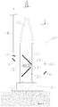
- FIG1 show(s) the longitudinal cross section of the general principle for an embodiment combining two optical spectroscopic or photometric techniques.
- the drawing shows the probe body (9) mounted in the product container wall (10), where the probe tip and window (1) are flush with the inner wall of the container and the probe is sealed off to the vessel by a seal (12) that can be specific for each application.
- the probe in the shown embodiment has two optical connections to spectroscopic or photometric techniques (13a and 13b). Each technique has its own source of excitation radiation that is entering the probe body through optical channels (5 and 5'). Depending on the chosen spectroscopic or photometric technique, the excitation radiation will need to be focussed, diverged or collimated by lenses (3) to the correct beam diameter in the probe.
- the radiation will be focussed at a certain depth like in the product container as in 7 or will be collimated as in 8.
- the lenses will need to be of a different configuration.
- Most of the commercially available spectroscopic or photometric techniques have their own radiation sources which are not designed to be used in combination with other spectroscopic or photometric techniques, therefore, it might be necessary to install filters (4) to remove parts of the excitation radiation of one technology that could influence the other.
- these filters are mounted behind the lenses but there is no reason the filter cannot be mounted before the lenses or even between the excitation source and the optical channel or the filter could be integrated in the focussing lens.
- a cut-off filter might be installed in the NIR light source, that is typically generating a very broad wavelength range, to prevent light of interfering wavelengths (mostly the wavelengths below about 1000 nm) to reach the detection channel from the Raman system by internal reflections.
- the excitation radiation then interferes with the product to be analysed and the returning signal is then focussed into the detection optical channels (6 and 6') by means of focussing optics (3).
- These focussing optics are designed to channel as much signal as possible to each individual channel.
- a filter can be installed in the optical path, either before, after or in the lens or just before the analysis instrument.
- the quality of the analysis highly depends on the absence of product adhesion to the observation window. It has been shown in literature that heating up the window has a prohibiting effect on this effect for some product and therefore, the probe can be equipped with electrical heating as shown by the heating sheet (2) in Fig 1 .
- a slightly different embodiment of the invention described above could have the optical channels ending at optical connectors at the end of the probe as shown in Fig 2 . This makes the system easier to handle during the mounting phase or the storage. Additional advantages exist for such a configuration when the optical channel is broken between the probe and the analyser. The replacement cost will be much lower and replacement time much faster in such an embodiment.
- Figure 5 shows a cross section of the preferred embodiment of a combined NIR Raman probe: the NIR excitation radiation source is equipped with a cut-off filter (both not shown) and the light is transmitted to the probe using a fibre bundle.
- the fibre bundle enters the probe and the drawing by the top and its individual fibres (2) end up evenly spaced at the top of a parabolic concentrator (3) that minimizes losses and backscattering while focusing the light onto the product through the window (1).
- the Raman excitation laser enters the probe through a optical channel (4) and is collimated to the desired diameter using an integrated lens (5).
- the collimated laser beam is then directed towards through an opening in the cylinder of fibres from the NIR light source by a mirror (6) and directed towards the window (1) by using a dichroic mirror (7). Both excitation radiations interfere with the product and the resulting radiation enters the probe back through the window (1).
- the dichroic mirror (7) is preventing any specular reflection from the laser beam to enter the detection optical channels while the lens (8) behind it is focussing the radiation towards the optical channel of the NIR system (9) to maximize the light return to the analyser while a second dichroic mirror (7') and a second mirror (6') guide the lower part of the signal back to the Raman optical channel after passing through an additional bandpass filter (11).
- Figure 6 presents in more detail a different embodiment of the NIR Raman probe from FIG. 5 where the NIR and Raman channel are using individual windows set in the tip of the probe.
- Example 3 Enhanced modelling using NIRand Raman simultaneously.
- a Raman-NIR probe can perform better than the two individual systems:
- the penetration of NIR light in packed powder beds is typically between 0,5 and 1 mm according to literature while that of the Raman excitation laser is easily over 1mm.
- the Raman signal will, as a consequence will be less vulnerable for adhesion of product on the window of the probe.
- NIR modelling usually takes a quality parameter into account to evaluate the current spectrum used for modelling against the population used to make the model. This however cannot discriminate between a normal sample high in a certain component of a mixture and that mixture component being permanently adhered to the window of the probe.
- the NIR and the Raman in one probe, will show a slow drift in the NIR signal while the Raman signal remains much more stable, indicating product adhesion to the window of the probe.
- the present invention is not restricted to any form of realization described previously and that some modifications can be added to the presented example of fabrication without reappraisal of the appended claims.
- the present invention has been described referring to the combination of Raman and NIR in one probe but it is clear that the invention can be applied to the combination of LIF and NIR for instance or to more than two techniques combined in one probe or to any other combination of spectroscopic or photometric techniques.
Landscapes
- Physics & Mathematics (AREA)
- Health & Medical Sciences (AREA)
- Life Sciences & Earth Sciences (AREA)
- Chemical & Material Sciences (AREA)
- Analytical Chemistry (AREA)
- Biochemistry (AREA)
- General Health & Medical Sciences (AREA)
- General Physics & Mathematics (AREA)
- Immunology (AREA)
- Pathology (AREA)
- Spectroscopy & Molecular Physics (AREA)
- Nuclear Medicine, Radiotherapy & Molecular Imaging (AREA)
- Investigating, Analyzing Materials By Fluorescence Or Luminescence (AREA)
Priority Applications (2)
| Application Number | Priority Date | Filing Date | Title |
|---|---|---|---|
| EP19178822.3A EP3748337A1 (de) | 2019-06-06 | 2019-06-06 | Sonde zur gleichzeitigen analyse mit verschiedenen spektroskopischen techniken und entsprechendes verfahren |
| BE20205393A BE1027312B1 (nl) | 2019-06-06 | 2020-06-03 | Verbeterde sonde voor gecombineerde electromagnetisch spectra of optische analyse en zijn gebruik/methode |
Applications Claiming Priority (1)
| Application Number | Priority Date | Filing Date | Title |
|---|---|---|---|
| EP19178822.3A EP3748337A1 (de) | 2019-06-06 | 2019-06-06 | Sonde zur gleichzeitigen analyse mit verschiedenen spektroskopischen techniken und entsprechendes verfahren |
Publications (1)
| Publication Number | Publication Date |
|---|---|
| EP3748337A1 true EP3748337A1 (de) | 2020-12-09 |
Family
ID=66776248
Family Applications (1)
| Application Number | Title | Priority Date | Filing Date |
|---|---|---|---|
| EP19178822.3A Withdrawn EP3748337A1 (de) | 2019-06-06 | 2019-06-06 | Sonde zur gleichzeitigen analyse mit verschiedenen spektroskopischen techniken und entsprechendes verfahren |
Country Status (2)
| Country | Link |
|---|---|
| EP (1) | EP3748337A1 (de) |
| BE (1) | BE1027312B1 (de) |
Citations (10)
| Publication number | Priority date | Publication date | Assignee | Title |
|---|---|---|---|---|
| US611852A (en) | 1898-10-04 | Trip mechanism for cars | ||
| US5044755A (en) * | 1989-03-03 | 1991-09-03 | Lt Industries | Probe for transmitting and receiving light from a sample |
| US6873409B1 (en) | 1998-11-17 | 2005-03-29 | Kaiser Optical Systems | Optical probe with sampling window cleaning configuration |
| US20080084555A1 (en) * | 2006-10-06 | 2008-04-10 | Woo Sik Yoo | Raman and photoluminescence spectroscopy |
| US20080212077A1 (en) * | 2005-06-27 | 2008-09-04 | Colin Jeffress | Spectroscopic Lance for Bulk Sampling |
| US20080212087A1 (en) | 2005-07-15 | 2008-09-04 | Joachim Mannhardt | Apparatus for the Electromagnetic Spectrum or Optical Analysis, in Particular Photometric, Spectrophotometric or Image Analysis |
| US8730467B2 (en) | 2009-05-28 | 2014-05-20 | Indatech | Spectroscopic probe and method for detecting an inhomogeneity |
| US20140340683A1 (en) | 2012-01-25 | 2014-11-20 | Bayer Intellectual Property Gmbh | Reflection probe |
| US20150377787A1 (en) * | 2013-02-14 | 2015-12-31 | British Columbia Cancer Agency Branch | Integrated spectral probe for raman, reflectance and fluorescence spectral measurements |
| US20160299060A1 (en) * | 2015-04-10 | 2016-10-13 | Blaze Metrics, LLC | System and method for simultaneously performing multiple optical analyses of liquids and particles in a fluid |
-
2019
- 2019-06-06 EP EP19178822.3A patent/EP3748337A1/de not_active Withdrawn
-
2020
- 2020-06-03 BE BE20205393A patent/BE1027312B1/nl active IP Right Grant
Patent Citations (10)
| Publication number | Priority date | Publication date | Assignee | Title |
|---|---|---|---|---|
| US611852A (en) | 1898-10-04 | Trip mechanism for cars | ||
| US5044755A (en) * | 1989-03-03 | 1991-09-03 | Lt Industries | Probe for transmitting and receiving light from a sample |
| US6873409B1 (en) | 1998-11-17 | 2005-03-29 | Kaiser Optical Systems | Optical probe with sampling window cleaning configuration |
| US20080212077A1 (en) * | 2005-06-27 | 2008-09-04 | Colin Jeffress | Spectroscopic Lance for Bulk Sampling |
| US20080212087A1 (en) | 2005-07-15 | 2008-09-04 | Joachim Mannhardt | Apparatus for the Electromagnetic Spectrum or Optical Analysis, in Particular Photometric, Spectrophotometric or Image Analysis |
| US20080084555A1 (en) * | 2006-10-06 | 2008-04-10 | Woo Sik Yoo | Raman and photoluminescence spectroscopy |
| US8730467B2 (en) | 2009-05-28 | 2014-05-20 | Indatech | Spectroscopic probe and method for detecting an inhomogeneity |
| US20140340683A1 (en) | 2012-01-25 | 2014-11-20 | Bayer Intellectual Property Gmbh | Reflection probe |
| US20150377787A1 (en) * | 2013-02-14 | 2015-12-31 | British Columbia Cancer Agency Branch | Integrated spectral probe for raman, reflectance and fluorescence spectral measurements |
| US20160299060A1 (en) * | 2015-04-10 | 2016-10-13 | Blaze Metrics, LLC | System and method for simultaneously performing multiple optical analyses of liquids and particles in a fluid |
Also Published As
| Publication number | Publication date |
|---|---|
| BE1027312A1 (nl) | 2020-12-18 |
| BE1027312B1 (nl) | 2021-07-13 |
Similar Documents
| Publication | Publication Date | Title |
|---|---|---|
| US6897951B2 (en) | Probe assemblies for Raman spectroscopy | |
| JP4791625B2 (ja) | 分光光度・比濁検出ユニット | |
| US11156561B2 (en) | Device for analyzing a product to be analyzed located in a product space | |
| US5407638A (en) | Detector-cell adapted for continuous-flow absorption detection | |
| US6741348B2 (en) | Ultrasensitive spectrophotometer | |
| JP4229529B2 (ja) | 反射率および透過率による分光分析装置および方法並びに分光計用のプローブ | |
| US7990538B2 (en) | Signal processing for optical computing system | |
| US9182282B2 (en) | Multi-analyte optical computing system | |
| CN107664616B (zh) | 光谱测量设备 | |
| US6018389A (en) | Cone penetrometer fiber optic raman spectroscopy probe assembly | |
| KR20010033480A (ko) | 샘플링 장치 | |
| EP3344978B1 (de) | Vorrichtung und verfahren zur durchführung einer lichtabsorbierenden messung an einer testprobe und nachgiebigkeitsmessung an einer referenzprobe | |
| EP3748337A1 (de) | Sonde zur gleichzeitigen analyse mit verschiedenen spektroskopischen techniken und entsprechendes verfahren | |
| US9683927B2 (en) | Device for receiving small volume liquid samples | |
| US9976950B2 (en) | Optical detector module, measurement system and method of detecting presence of a substance in a test material | |
| WO2022031458A1 (en) | Absorbance spectroscopy analyzer and method of use | |
| WO2012007542A1 (en) | Optical measurement method and apparatus | |
| CN118076882A (zh) | 具有可变路径长度的浸没式探头 | |
| US20230375468A1 (en) | Multi-monochromatic light source system for slope spectroscopy | |
| Liauw et al. | Putting fiber-optical spectroscopy to work: in-line optical spectroscopy has come of age, helping to increase profitability and safety. | |
| Liu | Fiber-Optic Probes | |
| CN115901618A (zh) | 具有同轴激发和收集孔径的空间偏移拉曼探针 | |
| RU2352920C2 (ru) | Способ определения количественного содержания компонентов в смеси | |
| CN114112904A (zh) | 光学过程传感器、测量头、测量系统和校准验证方法 | |
| HU227140B1 (en) | Method and apparatus for determining the absorbtion of weakly absorbing and/or scattering samples |
Legal Events
| Date | Code | Title | Description |
|---|---|---|---|
| PUAI | Public reference made under article 153(3) epc to a published international application that has entered the european phase |
Free format text: ORIGINAL CODE: 0009012 |
|
| STAA | Information on the status of an ep patent application or granted ep patent |
Free format text: STATUS: THE APPLICATION HAS BEEN PUBLISHED |
|
| AK | Designated contracting states |
Kind code of ref document: A1 Designated state(s): AL AT BE BG CH CY CZ DE DK EE ES FI FR GB GR HR HU IE IS IT LI LT LU LV MC MK MT NL NO PL PT RO RS SE SI SK SM TR |
|
| AX | Request for extension of the european patent |
Extension state: BA ME |
|
| STAA | Information on the status of an ep patent application or granted ep patent |
Free format text: STATUS: THE APPLICATION IS DEEMED TO BE WITHDRAWN |
|
| 18D | Application deemed to be withdrawn |
Effective date: 20210610 |