EP2767869A1 - Method for manufacturing a one-piece micromechanical part comprising at least two separate levels - Google Patents
Method for manufacturing a one-piece micromechanical part comprising at least two separate levels Download PDFInfo
- Publication number
- EP2767869A1 EP2767869A1 EP20130155068 EP13155068A EP2767869A1 EP 2767869 A1 EP2767869 A1 EP 2767869A1 EP 20130155068 EP20130155068 EP 20130155068 EP 13155068 A EP13155068 A EP 13155068A EP 2767869 A1 EP2767869 A1 EP 2767869A1
- Authority
- EP
- European Patent Office
- Prior art keywords
- substrate
- micromechanical
- electrically conductive
- metal part
- piece
- Prior art date
- Legal status (The legal status is an assumption and is not a legal conclusion. Google has not performed a legal analysis and makes no representation as to the accuracy of the status listed.)
- Withdrawn
Links
Images


Classifications
-
- H—ELECTRICITY
- H03—ELECTRONIC CIRCUITRY
- H03H—IMPEDANCE NETWORKS, e.g. RESONANT CIRCUITS; RESONATORS
- H03H3/00—Apparatus or processes specially adapted for the manufacture of impedance networks, resonating circuits, resonators
- H03H3/007—Apparatus or processes specially adapted for the manufacture of impedance networks, resonating circuits, resonators for the manufacture of electromechanical resonators or networks
- H03H3/0072—Apparatus or processes specially adapted for the manufacture of impedance networks, resonating circuits, resonators for the manufacture of electromechanical resonators or networks of microelectro-mechanical resonators or networks
-
- B—PERFORMING OPERATIONS; TRANSPORTING
- B81—MICROSTRUCTURAL TECHNOLOGY
- B81C—PROCESSES OR APPARATUS SPECIALLY ADAPTED FOR THE MANUFACTURE OR TREATMENT OF MICROSTRUCTURAL DEVICES OR SYSTEMS
- B81C99/00—Subject matter not provided for in other groups of this subclass
- B81C99/0075—Manufacture of substrate-free structures
- B81C99/008—Manufacture of substrate-free structures separating the processed structure from a mother substrate
-
- G—PHYSICS
- G03—PHOTOGRAPHY; CINEMATOGRAPHY; ANALOGOUS TECHNIQUES USING WAVES OTHER THAN OPTICAL WAVES; ELECTROGRAPHY; HOLOGRAPHY
- G03F—PHOTOMECHANICAL PRODUCTION OF TEXTURED OR PATTERNED SURFACES, e.g. FOR PRINTING, FOR PROCESSING OF SEMICONDUCTOR DEVICES; MATERIALS THEREFOR; ORIGINALS THEREFOR; APPARATUS SPECIALLY ADAPTED THEREFOR
- G03F7/00—Photomechanical, e.g. photolithographic, production of textured or patterned surfaces, e.g. printing surfaces; Materials therefor, e.g. comprising photoresists; Apparatus specially adapted therefor
-
- G—PHYSICS
- G04—HOROLOGY
- G04B—MECHANICALLY-DRIVEN CLOCKS OR WATCHES; MECHANICAL PARTS OF CLOCKS OR WATCHES IN GENERAL; TIME PIECES USING THE POSITION OF THE SUN, MOON OR STARS
- G04B15/00—Escapements
- G04B15/14—Component parts or constructional details, e.g. construction of the lever or the escape wheel
-
- B—PERFORMING OPERATIONS; TRANSPORTING
- B81—MICROSTRUCTURAL TECHNOLOGY
- B81B—MICROSTRUCTURAL DEVICES OR SYSTEMS, e.g. MICROMECHANICAL DEVICES
- B81B2201/00—Specific applications of microelectromechanical systems
- B81B2201/03—Microengines and actuators
- B81B2201/035—Microgears
-
- G—PHYSICS
- G03—PHOTOGRAPHY; CINEMATOGRAPHY; ANALOGOUS TECHNIQUES USING WAVES OTHER THAN OPTICAL WAVES; ELECTROGRAPHY; HOLOGRAPHY
- G03F—PHOTOMECHANICAL PRODUCTION OF TEXTURED OR PATTERNED SURFACES, e.g. FOR PRINTING, FOR PROCESSING OF SEMICONDUCTOR DEVICES; MATERIALS THEREFOR; ORIGINALS THEREFOR; APPARATUS SPECIALLY ADAPTED THEREFOR
- G03F7/00—Photomechanical, e.g. photolithographic, production of textured or patterned surfaces, e.g. printing surfaces; Materials therefor, e.g. comprising photoresists; Apparatus specially adapted therefor
- G03F7/0002—Lithographic processes using patterning methods other than those involving the exposure to radiation, e.g. by stamping
-
- Y—GENERAL TAGGING OF NEW TECHNOLOGICAL DEVELOPMENTS; GENERAL TAGGING OF CROSS-SECTIONAL TECHNOLOGIES SPANNING OVER SEVERAL SECTIONS OF THE IPC; TECHNICAL SUBJECTS COVERED BY FORMER USPC CROSS-REFERENCE ART COLLECTIONS [XRACs] AND DIGESTS
- Y10—TECHNICAL SUBJECTS COVERED BY FORMER USPC
- Y10T—TECHNICAL SUBJECTS COVERED BY FORMER US CLASSIFICATION
- Y10T29/00—Metal working
- Y10T29/49—Method of mechanical manufacture
- Y10T29/49002—Electrical device making
Definitions
- the invention relates to a method for manufacturing a monobloc micromechanical component comprising at least two distinct levels.
- the object of the present invention is to overcome all or part of the disadvantages mentioned above by proposing an alternative method of manufacturing a piece of micromechanical monoblock comprising at least two distinct levels, less expensive to implement.
- each one-piece micromechanical piece comprising at least two distinct levels is formed from a metal piece in a single pattern formed by a LIGA process which is then machined directly on the substrate in order to benefit from the positioning. precise of each metal part on the substrate.
- the invention relates to a timepiece characterized in that it comprises a piece of micromechanical monobloc at least two distinct levels obtained according to one of the previous variants.
- the object of the present invention is to provide a method for manufacturing a piece of micromechanical monoblock comprising at least two distinct levels which is cheaper to implement.
- the present invention also aims to manufacture all or part of a micromechanical part from this process.
- the micromechanical part is intended to be mounted preferentially in a timepiece.
- the invention relates to a method 1 for manufacturing a single-piece micromechanical part 31, 41, 61, 91 comprising at least two distinct levels.
- a first step 3, as illustrated in FIG. figure 1 is intended to form a silicon substrate 2 whose upper surface 4 is electrically conductive.
- the upper surface 4 is electrically conductive by doping the substrate 2 in silicon and / or by the deposition of an electrically conductive layer on the silicon substrate 2.
- step 9 it is very important that the adhesion of the future galvanic deposit against the substrate 2 be as strong as possible. Indeed, it is essential for step 9 that the metal part 21, 51, 81 is very strongly fixed against the upper surface 4 and, incidentally, against the substrate 2.
- the silicon substrate 2 has a thickness of between 0.3 and 1 mm.
- the latter would preferably be based on gold, that is to say in pure gold or one of its alloys.
- it could be, for example, deposited by physical or chemical vapor deposition or any other method of deposition.
- Process 1 continues, as illustrated in figure 2 , with a second step 5 for structuring a mold from a photosensitive resin 6 to produce cavities 8 whose bottom is formed by the electrically conductive upper face 4 of the substrate 2.
- FIG. 2 is only a simplified representation and very complex forms can be structured.
- several cavities 8, not necessarily of identical shapes, can be structured in the resin 6 during step 5 so that several micromechanical parts 31, 41, 61, 91 can be formed on the same substrate 2.
- Step 5 preferably comprises the three phases.
- Step 5 comprises a first phase intended to deposit a photoresist layer 6 on the electrically conductive upper surface 4 of the substrate 2.
- a phase can be obtained by centrifugal coating or by ultrasonic spraying.
- the second phase is intended to selectively illuminate a portion of the photosensitive resin. It is therefore understood that depending on the nature of the photosensitive resin, that is to say if the resin is of the positive or negative type, the illumination will be focused on the desired future cavities 8 or on the parts other than the desired future cavities 8.
- the step 5 ends with a third phase intended to develop the selectively illuminated photosensitive resin 6 in order to structure the mold, that is to say harden the photosensitive resin 6 remaining between the cavities 8.
- This third phase is generally obtained by etching to form the cavities 8 followed by a heat treatment to harden the resin still present.
- Process 1 continues, as illustrated in figure 3 , with a third step 7 for filling the cavities 8 of the mold by electroplating to form a metal part 21, 51, 81.
- the metal part 21, 51, 81 has the same pattern in projection. It is therefore understood that the LIGA method does not involve additional difficulties in implementing it, for example, other patterns on higher levels.
- the method 1 makes it possible, thanks to the very precise step 5 of photolithography, to obtain a metal part 21, 51, 81 with external and, possibly, internal dimensions of a high precision appropriate to respect the very high tolerances of a micromechanical component in the field of watchmaking.
- internal dimensions it should be understood that from any part of structured resin 6 which is enclosed in cavities 8, perforations and / or holes in the metal part 21, 51, 81 can be directly formed during Step 7.
- micromechanical parts 31, 41, 61, 91 for the watch industry, it is preferred to use a material which is tribologically advantageous for contacts with ruby pieces, of steel or brass. In addition, a low sensitivity to magnetic fields is sought. Finally, in order to facilitate step 9, it is also preferable that the material is not too hard. Thus, in view of the above constraints, it appeared particularly suitable to fill the cavities 8 during step 7 with an alloy formed of nickel and phosphorus (NiP) and in particular such an alloy whose proportion of phosphorus is substantially equal to 12% (NiP12).
- NiP nickel and phosphorus
- Process 1 continues, as illustrated in figure 4 with a step 9 for selectively machining a portion of the metal part 21, 51, 81 to form a micromechanical part 31, 41, 61, 91 at at least two distinct levels.
- the metal part 21, 51, 81 having the same pattern in projection is then modified in its thickness to form at least two patterns on several levels.
- the desired micromechanical part 31, 41, 61, 91 is thus obtained without having to form several stacked levels from successive LIGA processes.
- each metal part 21, 51, 81 will be subject to strong constraints. Therefore, if the adhesion is not sufficient, the method 1 loses the benefit of the precise positioning of each metal part 21, 51, 81 on the substrate 2, or even risk of shearing the metal parts 21, 51, 81 to the point to dissociate them from the substrate 2.
- step 9 because of the precise positioning of each metal part 21, 51, 81 on the substrate 2, it is possible during step 9, to machine each metal part 21, 51, 81 still on the substrate 2 with a PLC in precise dimensions. Note that, even if step 9 is intended to machine each metal part 21, 51, 81, part of the structured resin 6 can however also be machined by the stresses induced by the tools. used or volumes to be removed as shown by the clearances visible at figure 4 .
- process 1 ends, as illustrated in figure 5 , with step 11 for releasing the micromechanical part 31, 41, 61, 91 of the substrate 2 and the photosensitive resin 6.
- the step 11 is intended to remove the photoresist 6 then in a second phase 14, intended to remove the substrate 2.
- the phase 12 can be obtained, for example, by a plasma etching while the phase 14 is, preferably, obtained by etching.
- the phase 14 is, preferably, obtained by etching.
- an electrically conductive layer would be used to form the electrically conductive upper surface 4
- the latter would, also during phase 14, be removed and, optionally, recovered using a selective chemical attack. .
- the method 1 may comprise an optional step 10, between step 7 and step 9, intended to level by grounding the mold formed of photosensitive resin 6 and the metal part 21, 51, 81.
- This step optional may be desired to ensure the dimensions of the micromechanical part 31, 41, 61, 91, that is to say, be sure that the mold is completely filled.
- the method 1 can, as illustrated in FIG. figure 6 , comprising an optional phase 16, between the phase 12 and the phase 14, for depositing a coating 13 on the micromechanical part micromechanical part assembly 31, 41, 61, 91 - substrate 2.
- a phase 16 can be obtained for example, by physical or chemical vapor deposition, electroplating or any other type of deposit.
- a micromechanical part 31, 41, 61, 91 partially coated with a layer 13 is then obtained.
- the layer 13 is intended to improve the tribology of the micromechanical part 31, 41 , 61, 91 as, for example, formed from an allotrope of carbon such as graphene or carbon in diamond form.
- the layer 13 can also be used for another function such as changing the color or the hardness of the micromechanical part 31, 41, 61, 91.
- FIG. 8 to 16 Examples of watchmaking applications are presented using three variants illustrated in Figures 8 to 16 .
- a metal part 21 obtained in step 7 of method 1 is shown. It is generally in the form of a double-toothed star 22, 24 having a central hole 26.
- step 11 of the method 1 it is thus possible to obtain a micromechanical part in the form of an escape wheel 31 illustrated in FIG. figure 9 or an escape wheel 41 shown in FIG. figure 10 both being in one piece and having at least two distinct levels, coated or not with a layer 13.
- the metal part 21 has been machined at the eight arms 33, each end forms the toothing 22 in a lower level.
- the remainder of the metal part 21 remained unchanged, in particular at the hole 26 and the eight arms 35, each end of which forms the second toothing 22 in the lower level and in a higher level.
- the metal part 21 has been machined at the eight arms 43, each end forms the toothing 22 in a lower level.
- the surrounding hole 26 has been machined to leave the hole 26 present in the lower level.
- the eight arms 45 and part of the upper level have been machined so that only the ends of the arm 45 keeping the second toothing 22 in the lower level and in the upper level.
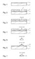
- a metal part 51 obtained during step 7 of the method 1 is presented. It is generally in the form of an H-shaped part comprising two parallel parts 53, 55 connected to each other by a transverse portion 57. As visible in FIG. the figure 11 , the transverse portion 57 has a central portion 56 whose section is more flared than the rest of the portion.
- step 11 of method 1 it is thus possible to obtain a micromechanical part in the form of a fork 61 illustrated in FIG. figure 12 monobloc and comprising at least two distinct levels coated or not with a layer 13.
- the metal part 51 has been machined at the two parts 53, 55 parallel in two depths, that is to say, forming three levels and at the non-flared portion of the transverse portion 57 at a single depth.
- the fork 61 thus comprises all the parts 53, 55 parallel only to the lower level by forming two horns 62, 64.
- An intermediate level only partially comprises the parallel portions 53, 55 and the non-flared portion of the transverse portion 57 forming shoulders 63 and 65.
- the central portion 56 of the transverse portion 57 is retained from the metal part 51 by forming only in the upper level a tenon.
- the fork 61 can then be mounted, by driving the central portion 56 forming tenon, in the hole 76 of a rod 73 to form an anchor 71.
- the rod 73 can itself be obtained by a method LIGA with a sting 78 in one piece.
- the rod 73 can be equipped with vanes 75, 77 at its arms 72, 74 and with a pivot axis 79.
- all or part of the anchor 71 can also be obtained using method 1 according to the invention.
- the pallets 75, 77, the rod 73, the dart 78, the hole 76 could be monoblock and obtained from the method 1 according to the invention.
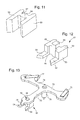
- a metal part 81 obtained in step 7 of method 1 is presented. It is generally in the form of a U-shaped part comprising two parallel portions 83, 85 connected to each other by a base 87. As visible in FIG. figure 14 , the base is thicker than the part 83, 85 parallel to allow the formation of an ajoint 86 substantially cross-shaped.
- step 11 of method 1 it is thus possible to obtain a micromechanical part in the form of a fork 91 illustrated in FIG. figure 15 monobloc and comprising at least two distinct levels with or without a layer 13.
- the metal part 81 has been machined at the two parallel portions 83, 85 at a single depth and at the base 87 at two depths, that is, by forming three levels,
- the fork 61 thus comprises all the parts 83, 85 parallel only at the lower level forming two horns 92, 94.
- An intermediate level only partially comprises the base 87 forming a cylinder 93 tapering by a shoulder 95 to form the level superior.
- the narrowing is used to release the openwork 86 in the upper level and form four pins 96, 97, 98, 99.
- the fork 91 can then be mounted, by driving the pins 96, 97, 98, 99, into the holes 106 of a rod 103 to form an anchor 101.
- the rod 103 can itself be obtained by a LIGA method with a dart 108 in one piece.
- the rod 103 can be equipped, in a similar manner in the second variant, pallets at its arms 102, 104 and a pivot axis.
- all or part of the anchor 101 can also be obtained using the method 1 according to the invention.
- the pallets, the rod 103, the dart 108, the holes 106 could be monoblock and obtained from the method 1 according to the invention.
- micromechanical 31, 41, 61, 91 monobloc benefits from the precision of machining to preserve manufacturing costs.
- a micromechanical part 31, 41, 61, 91 comprising one piece with at least two distinct levels is obtained which is much less difficult to manufacture by keeping the external parts 22, 24, 53, 55, 56, 83, 85 and possibly internal 26, 86 very precise.
- the present invention is not limited to the illustrated example but is susceptible of various variations and modifications that will occur to those skilled in the art.
- the micromechanical parts 31, 41, 61, 91 can not be limited to an entire or part of a mobile or an anchor.
- Other watch parts can be considered as, in particular, bridges, plates or pendulums.
Landscapes
- Engineering & Computer Science (AREA)
- Manufacturing & Machinery (AREA)
- Physics & Mathematics (AREA)
- General Physics & Mathematics (AREA)
- Microelectronics & Electronic Packaging (AREA)
- Micromachines (AREA)
- Mechanical Treatment Of Semiconductor (AREA)
Abstract
Description
L'invention se rapporte à un procédé de fabrication d'une pièce de micromécanique monobloc comportant au moins deux niveaux distincts.The invention relates to a method for manufacturing a monobloc micromechanical component comprising at least two distinct levels.
Il est connu de former des pièces métalliques à plusieurs niveaux distincts à l'aide de procédé du type LIGA successifs, c'est-à-dire à partir de couches empilées comportant un moule structuré en résine et un métal dans les creux du moule déposé par galvanoplastie.It is known to form metal parts at several different levels using successive LIGA type processes, that is to say from stacked layers comprising a mold structured resin and a metal in the hollow of the mold deposited by electroplating.
Toutefois, ces procédés successifs pour former plusieurs niveaux sont difficiles à mettre en oeuvre car il est nécessaire de correctement référencer les niveaux entre eux. De plus, il est apparu que cette difficulté engendrait des couts très supérieurs par rapport à deux dépôts galvaniques à un seul niveau.However, these successive methods for forming several levels are difficult to implement because it is necessary to correctly reference the levels between them. In addition, it appeared that this difficulty generated much higher costs compared to two galvanic deposits at a single level.
Le but de la présente invention est de pallier tout ou partie les inconvénients cités précédemment en proposant un procédé alternatif de fabrication d'une pièce de micromécanique monobloc comportant au moins deux niveaux distincts, moins cher à mettre en oeuvre.The object of the present invention is to overcome all or part of the disadvantages mentioned above by proposing an alternative method of manufacturing a piece of micromechanical monoblock comprising at least two distinct levels, less expensive to implement.
A cet effet, l'invention se rapporte à un procédé de fabrication d'une pièce de micromécanique monobloc comportant au moins deux niveaux distincts caractérisé en ce qu'il comporte les étapes suivantes :
- a) former un substrat en silicium dont la surface supérieure est électriquement conductrice ;
- b) structurer un moule à partir d'une résine photosensible afin de fabriquer des cavités dont le fond est formé par ladite face supérieure électriquement conductrice ;
- c) remplir les cavités du moule par galvanoplastie pour former une pièce métallique ;
- d) usiner sélectivement une partie de la pièce métallique afin de former une pièce de micromécanique monobloc à au moins deux niveaux distincts ;
- e) libérer la pièce de micromécanique du substrat et de la résine photosensible.
- a) forming a silicon substrate whose upper surface is electrically conductive;
- b) structuring a mold from a photosensitive resin to make cavities whose bottom is formed by said electrically conductive upper face;
- c) filling the cavities of the mold by electroplating to form a metal part;
- d) selectively machining a portion of the metal part to form a one-piece micromechanical part at at least two distinct levels;
- e) releasing the micromechanical part of the substrate and the photoresist.
On comprend avantageusement selon l'invention que chaque pièce de micromécanique monobloc comportant au moins deux niveaux distincts est formée à partir d'une pièce métallique selon un motif unique formé par un procédé LIGA qui est ensuite usinée directement sur le substrat afin de bénéficier du positionnement précis de chaque pièce métallique sur le substrat.It is advantageously understood according to the invention that each one-piece micromechanical piece comprising at least two distinct levels is formed from a metal piece in a single pattern formed by a LIGA process which is then machined directly on the substrate in order to benefit from the positioning. precise of each metal part on the substrate.
Par conséquent, les cotes externes et, éventuellement, internes restent à la grande précision induit par le procédé LIGA et le reste de la pièce de micromécanique monobloc bénéficie de la précision de l'usinage, moins avantageuse par rapport au procédé LIGA, afin de préserver les couts de fabrication. On obtient donc une pièce de micromécanique monobloc comportant au moins deux niveaux distincts qui est beaucoup moins difficile à fabriquer en gardant les parties externes et, éventuellement, internes d'une très grande précision.Consequently, the external and, possibly, internal dimensions remain at the high precision induced by the LIGA process and the rest of the monobloc micromechanical part benefits from the precision of the machining, which is less advantageous compared to the LIGA process, in order to preserve manufacturing costs. A piece of micromechanical monobloc having at least two distinct levels is thus obtained which is much less difficult to manufacture by keeping the external and, possibly, internal parts of a very high precision.
Conformément à d'autres caractéristiques avantageuses de l'invention :
- la surface supérieure est rendue électriquement conductrice par le dopage du substrat en silicium et/ou par le dépôt d'une couche électriquement conductrice sur le substrat en silicium ;
- le substrat en silicium comporte une épaisseur comprise entre 0,3 et 1 mm ;
- l'étape b) comporte les phases f) : déposer une couche de résine photosensible sur la surface supérieure électriquement conductrice du substrat, g) : illuminer sélectivement une partie de la résine photosensible et h) : développer la résine photosensible afin de structurer le moule ;
- la pièce métallique est formée à base de nickel-phosphore comme du NiP ou du NiP12 ;
- le procédé comporte en outre entre l'étape c) et l'étape d), l'étape i) : mettre à niveau, par rodage, le moule et la pièce métallique ;
- lors de l'étape e), le procédé comporte les phases j) : retirer la résine photosensible et k) : retirer le substrat ;
- entre la phase j) et la phase k), le procédé comporte en outre la phase l) : déposer un revêtement sur l'ensemble pièce de micromécanique - substrat ;
- la phase l) est réalisée par dépôt physique ou chimique en phase vapeur ou par galvanoplastie ;
- plusieurs pièces de micromécanique sont formées sur le même substrat.
- the upper surface is rendered electrically conductive by doping the silicon substrate and / or by depositing an electrically conductive layer on the silicon substrate;
- the silicon substrate has a thickness of between 0.3 and 1 mm;
- step b) comprises the phases f): depositing a photoresist layer on the electrically conductive upper surface of the substrate, g): selectively illuminating a portion of the photoresist and h): developing the photoresist in order to structure the mold ;
- the metal part is formed based on nickel-phosphorus such as NiP or NiP12;
- the method further comprises between step c) and step d), step i): leveling, by running-in, the mold and the metal part;
- during step e), the method comprises the phases j): removing the photoresist and k): removing the substrate;
- between phase j) and phase k), the method further comprises phase l): depositing a coating on the micromechanical part-substrate assembly;
- phase l) is carried out by physical or chemical vapor deposition or by electroplating;
- several micromechanical parts are formed on the same substrate.
De plus, l'invention se rapporte à une pièce d'horlogerie caractérisée en ce qu'elle comporte une pièce de micromécanique monobloc à au moins deux niveaux distincts obtenue selon l'une des variantes précédentes.In addition, the invention relates to a timepiece characterized in that it comprises a piece of micromechanical monobloc at least two distinct levels obtained according to one of the previous variants.
D'autres particularités et avantages ressortiront clairement de la description qui en est faite ci-après, à titre indicatif et nullement limitatif, en référence aux dessins annexés, dans lesquels :
- les
figures 1 à 5 sont des représentations d'étapes successives d'un procédé selon un premier mode de réalisation de l'invention ; - les
figures 6 et 7 sont des représentations d'étapes finales d'un procédé selon un deuxième mode de réalisation de l'invention ; - les
figures 8 à 10 sont des représentations d'une pièce métallique électroformée puis usinée à l'aide d'un procédé selon une première variante de l'invention ; - les
figures 11 à 13 sont des représentations d'une pièce métallique électroformée puis usinée à l'aide d'un procédé selon une deuxième variante de l'invention puis assemblée ; - les
figures 14 à 16 sont des représentations de pièce métallique électroformée puis usinée à l'aide d'un procédé selon une troisième variante de l'invention puis assemblée ; - la
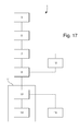
figure 17 est un schéma fonctionnel d'un procédé selon l'invention.
- the
Figures 1 to 5 are representations of successive steps of a method according to a first embodiment of the invention; - the
Figures 6 and 7 are final process representations of a method according to a second embodiment of the invention; - the
Figures 8 to 10 are representations of an electroformed metal part and then machined using a method according to a first variant of the invention; - the
Figures 11 to 13 are representations of a metal part electroformed and then machined using a method according to a second variant of the invention and assembled; - the
Figures 14 to 16 are representations of electroformed metal part and then machined using a method according to a third variant of the invention and assembled; - the
figure 17 is a block diagram of a method according to the invention.
Le but de la présente invention est de proposer un procédé de fabrication d'une pièce de micromécanique monobloc comportant au moins deux niveaux distincts qui soit moins cher à mettre en oeuvre. La présente invention a également pour but de fabriquer tout ou partie d'une pièce de micromécanique à partir de ce procédé. La pièce de micromécanique est destinée à être montée préférentiellement dans une pièce d'horlogerie. Bien entendu, il est également envisageable d'appliquer la présente invention dans d'autres domaines comme, notamment, l'aéronautique ou l'automobile.The object of the present invention is to provide a method for manufacturing a piece of micromechanical monoblock comprising at least two distinct levels which is cheaper to implement. The present invention also aims to manufacture all or part of a micromechanical part from this process. The micromechanical part is intended to be mounted preferentially in a timepiece. Of course, it is also conceivable to apply the present invention in other fields such as, in particular, aeronautics or automobiles.
Comme illustré à la
Selon le procédé 1, une première étape 3, comme illustrée à la
Dans tous les cas, il est très important que l'adhérence du futur dépôt galvanique contre le substrat 2 soit la plus forte possible. En effet, il est primordial pour l'étape 9 que la pièce métallique 21, 51, 81 soit très fortement fixée contre la surface supérieure 4 et, incidemment, contre le substrat 2.In all cases, it is very important that the adhesion of the future galvanic deposit against the
Préférentiellement selon l'invention, le substrat 2 en silicium comporte une épaisseur comprise entre 0,3 et 1 mm. De plus, dans le cas où une couche électriquement conductrice serait utilisée, cette dernière serait de manière préférée à base d'or, c'est-à-dire en or pur ou un de ses alliages. Enfin, elle pourrait être, par exemple, déposée par dépôt physique ou chimique en phase vapeur ou tout autre méthode de dépôt.Preferably according to the invention, the
Le procédé 1 se poursuit, comme illustré à la
Bien évidemment, la
L'étape 5 comporte préférentiellement les trois phases. L'étape 5 comporte une première phase destinée à déposer une couche de résine 6 photosensible sur la surface supérieure 4 électriquement conductrice du substrat 2. Une telle phase peut être obtenue par enduction centrifuge ou par pulvérisation à ultrasons. La deuxième phase est destinée à illuminer sélectivement une partie de la résine photosensible. On comprend donc que suivant la nature de la résine photosensible, c'est-à-dire si la résine est du type positive ou négative, l'illumination sera focalisée sur les futures cavités 8 souhaitées ou sur les parties autres que les futures cavités 8 souhaitées.
Enfin, l'étape 5 se termine avec une troisième phase destinée à développer la résine photosensible 6 sélectivement illuminée afin de structurer le moule, c'est-à-dire durcir la résine photosensible 6 restant entre les cavités 8. Cette troisième phase est généralement obtenue par une attaque chimique destinée à former les cavités 8 suivie d'un traitement thermique destinée à durcir la résine encore présente.Finally, the
Le procédé 1 se poursuit, comme illustré à la
Avantageusement selon l'invention, le procédé 1 permet, grâce à l'étape 5 très précise de photolithographie, d'obtenir une pièce métallique 21, 51, 81 avec des cotes externes et, éventuellement, internes d'une grande précision propre à respecter les tolérances très élevées d'une pièce de micromécanique dans le domaine de l'horlogerie. Par cotes internes, il faut comprendre, qu'à partir d'éventuelles parties de résine 6 structurée qui sont enclavée dans des cavités 8, des ajourages et/ou des trous dans la pièce métallique 21, 51, 81 peuvent être directement formés lors de l'étape 7.Advantageously according to the invention, the method 1 makes it possible, thanks to the very
Dans le but de mettre en oeuvre le procédé pour fabriquer des pièces de micromécanique 31, 41, 61, 91 pour l'horlogerie, il est préféré d'utiliser un matériau qui est tribologiquement avantageux pour des contacts avec des pièces en rubis, en acier ou en laiton. De plus, une faible sensibilité aux champs magnétiques est recherchée. Enfin, en vue de faciliter l'étape 9, il est également préférable que le matériau ne soit pas trop dur. Ainsi, au vu des contraintes ci-dessus, il est apparu particulièrement adapté de remplir les cavités 8 lors de l'étape 7 avec un alliage formé de nickel et de phosphore (NiP) et notamment un tel alliage dont la proportion de phosphore est sensiblement égale à 12% (NiP12).In order to implement the method for manufacturing
Le procédé 1 se poursuit, comme illustré à la
On comprend toute l'importance de la forte adhérence de chaque pièce métallique 21, 51, 81 contre la surface supérieure 4 du substrat 2. En effet, lors de l'usinage de l'étape 9, chaque pièce métallique 21, 51, 81 sera soumise à de fortes contraintes. Dès lors, si l'adhérence n'est pas suffisante, le procédé 1 perd le bénéfice du positionnement précis de chaque pièce métallique 21, 51, 81 sur le substrat 2, voire risque de cisailler les pièces métalliques 21, 51, 81 au point de les désolidariser du substrat 2.We understand the importance of the strong adhesion of each
Au contraire, avec cette forte adhérence, du fait du positionnement précis de chaque pièce métallique 21, 51, 81 sur le substrat 2, il est possible, lors de l'étape 9, d'usiner chaque pièce métallique 21, 51, 81 encore sur le substrat 2 avec un automate programmable selon des cotes précises. On remarque que, même si l'étape 9 est destinée à usiner chaque pièce métallique 21, 51, 81, une partie de la résine 6 structurée peut toutefois également être usinée par les contraintes induites par les outils utilisés ou les volumes à enlever comme illustré par les dégagements visibles à la
Enfin, Le procédé 1 se termine, comme illustré à la
Bien entendu, la présente invention ne se limite pas à l'exemple illustré mais est susceptible de diverses variantes et modifications qui apparaîtront à l'homme de l'art. En particulier, le procédé 1 peut comporter une étape optionnelle 10, entre l'étape 7 et l'étape 9, destinée à mettre à niveau par rodage le moule formée en résine photosensible 6 et la pièce métallique 21, 51, 81. Cette étape optionnelle peut être souhaitée pour garantir les cotes de la pièce de micromécanique 31, 41, 61, 91, c'est-à-dire être sûr que le moule est complètement rempli.Of course, the present invention is not limited to the illustrated example but is susceptible of various variations and modifications that will occur to those skilled in the art. In particular, the method 1 may comprise an
Il est également envisageable de profiter de la présence de plusieurs pièces métalliques 21, 51, 81 sur le même substrat 2 pour les revêtir d'une couche prédéterminée. Ainsi, le procédé 1 peut, comme illustré à la
A l'issue de la phase 14, on obtient alors une pièce de micromécanique 31, 41, 61, 91 partiellement revêtue d'une couche 13. Préférentiellement, la couche 13 est destinée à améliorer la tribologie de la pièce de micromécanique 31, 41, 61, 91 comme, par exemple, formée à partir d'un allotrope du carbone tel que du graphène ou du carbone sous forme diamant. Toutefois, la couche 13 peut également être utilisée pour une autre fonction comme changer la couleur ou la dureté de la pièce de micromécanique 31, 41, 61, 91.At the end of
Des exemples d'applications horlogères sont présentés à l'aide de trois variantes illustrées aux
Ainsi, dans le cas de la
De manière alternative, dans le cas de la
Dans une deuxième variante illustrée aux
A l'issue de l'étape 11 du procédé 1, on peut ainsi obtenir une pièce de micromécanique prenant la forme d'une fourchette 61 illustrée à la
Dans l'exemple de la
Comme visible à la
Dans une troisième variante illustrée aux
A l'issue de l'étape 11 du procédé 1, on peut ainsi obtenir une pièce de micromécanique prenant la forme d'une fourchette 91 illustrée à la
Dans l'exemple de la
Comme visible à la
Par conséquent, avantageusement selon l'invention, les cotes externes 22, 24, 53, 55, 56, 83, 85 et, éventuellement, internes 26, 86 restent à la grande précision induit par le procédé LIGA et le reste de la pièce de micromécanique 31, 41, 61, 91 monobloc bénéficie de la précision de l'usinage afin de préserver les couts de fabrication. On obtient donc une pièce de micromécanique 31, 41, 61, 91 monobloc comportant au moins deux niveaux distincts qui est beaucoup moins difficile à fabriquer en gardant les parties externes 22, 24, 53, 55, 56, 83, 85 et, éventuellement, internes 26, 86 d'une très grande précision.Therefore, advantageously according to the invention, the
Bien entendu, la présente invention ne se limite pas à l'exemple illustré mais est susceptible de diverses variantes et modifications qui apparaîtront à l'homme de l'art. En particulier, dans le domaine de l'horlogerie, les pièces de micromécanique 31, 41, 61, 91 ne sauraient se limiter à un tout ou partie d'un mobile ou d'une ancre. D'autres pièces horlogères peuvent être envisagées comme, notamment, des ponts, des platines ou des balanciers.Of course, the present invention is not limited to the illustrated example but is susceptible of various variations and modifications that will occur to those skilled in the art. In particular, in the field of watchmaking, the
De plus, comme expliqué ci-dessus, il est également envisageable d'appliquer la présente invention dans d'autres domaines que l'horlogerie comme, notamment, l'aéronautique ou l'automobile.In addition, as explained above, it is also conceivable to apply the present invention in other areas than watchmaking, such as aeronautics or automobiles.
Claims (11)
et, en ce qu'entre la phase j) et la phase k), le procédé (1) comporte en outre la phase suivante :
and in that between phase j) and phase k), the method (1) further comprises the following step:
Priority Applications (7)
| Application Number | Priority Date | Filing Date | Title |
|---|---|---|---|
| EP20130155068 EP2767869A1 (en) | 2013-02-13 | 2013-02-13 | Method for manufacturing a one-piece micromechanical part comprising at least two separate levels |
| EP14151480.2A EP2767870B1 (en) | 2013-02-13 | 2014-01-16 | Method for manufacturing a one-piece micromechanical part comprising at least two separate functional levels |
| IN562CH2014 IN2014CH00562A (en) | 2013-02-13 | 2014-02-07 | |
| US14/176,322 US9197183B2 (en) | 2013-02-13 | 2014-02-10 | Method of fabricating a single-piece micromechanical component including at least two distinct functional levels |
| JP2014025135A JP5899252B2 (en) | 2013-02-13 | 2014-02-13 | Method for manufacturing a single piece micromachine component with at least two different height functions |
| CN201410049720.7A CN103979483B (en) | 2013-02-13 | 2014-02-13 | Method of fabricating a single-piece micromechanical component including at least two distinct functional levels |
| HK15101179.4A HK1200799A1 (en) | 2013-02-13 | 2015-02-04 | Method of fabricating a single-piece micromechanical component including at least two distinct functional levels |
Applications Claiming Priority (1)
| Application Number | Priority Date | Filing Date | Title |
|---|---|---|---|
| EP20130155068 EP2767869A1 (en) | 2013-02-13 | 2013-02-13 | Method for manufacturing a one-piece micromechanical part comprising at least two separate levels |
Publications (1)
| Publication Number | Publication Date |
|---|---|
| EP2767869A1 true EP2767869A1 (en) | 2014-08-20 |
Family
ID=47877759
Family Applications (2)
| Application Number | Title | Priority Date | Filing Date |
|---|---|---|---|
| EP20130155068 Withdrawn EP2767869A1 (en) | 2013-02-13 | 2013-02-13 | Method for manufacturing a one-piece micromechanical part comprising at least two separate levels |
| EP14151480.2A Active EP2767870B1 (en) | 2013-02-13 | 2014-01-16 | Method for manufacturing a one-piece micromechanical part comprising at least two separate functional levels |
Family Applications After (1)
| Application Number | Title | Priority Date | Filing Date |
|---|---|---|---|
| EP14151480.2A Active EP2767870B1 (en) | 2013-02-13 | 2014-01-16 | Method for manufacturing a one-piece micromechanical part comprising at least two separate functional levels |
Country Status (6)
| Country | Link |
|---|---|
| US (1) | US9197183B2 (en) |
| EP (2) | EP2767869A1 (en) |
| JP (1) | JP5899252B2 (en) |
| CN (1) | CN103979483B (en) |
| HK (1) | HK1200799A1 (en) |
| IN (1) | IN2014CH00562A (en) |
Cited By (3)
| Publication number | Priority date | Publication date | Assignee | Title |
|---|---|---|---|---|
| WO2018172895A1 (en) * | 2017-03-24 | 2018-09-27 | Montblanc Montre Sa | Process for manufacturing a metal-ceramic timepiece component |
| EP3614205A1 (en) * | 2018-08-22 | 2020-02-26 | Nivarox-FAR S.A. | Method for manufacturing a timepiece component and component produced by this method |
| WO2023012035A1 (en) * | 2021-08-02 | 2023-02-09 | Rolex Sa | Method for manufacturing a timepiece component |
Families Citing this family (7)
| Publication number | Priority date | Publication date | Assignee | Title |
|---|---|---|---|---|
| JP6560250B2 (en) * | 2014-12-12 | 2019-08-14 | シチズン時計株式会社 | Watch part and method for manufacturing watch part |
| EP3035125B1 (en) * | 2014-12-19 | 2018-01-10 | Rolex Sa | Method for manufacturing a multi-level clock component |
| EP3168057A1 (en) * | 2015-11-11 | 2017-05-17 | Nivarox-FAR S.A. | Method for manufacturing a metal part with at least one optical illusion pattern |
| EP3171229A1 (en) * | 2015-11-19 | 2017-05-24 | Nivarox-FAR S.A. | Clock component |
| EP3171230B1 (en) * | 2015-11-19 | 2019-02-27 | Nivarox-FAR S.A. | Timepiece component with improved tribology |
| EP3453787B1 (en) | 2017-09-11 | 2020-02-19 | Patek Philippe SA Genève | Method for manufacturing a batch of multi-level micromechanical metal parts |
| WO2020147931A1 (en) | 2019-01-15 | 2020-07-23 | Heldeis Christoph | Method for implicit addressing of electronic units and corresponding units |
Citations (6)
| Publication number | Priority date | Publication date | Assignee | Title |
|---|---|---|---|---|
| US6458263B1 (en) * | 2000-09-29 | 2002-10-01 | Sandia National Laboratories | Cantilevered multilevel LIGA devices and methods |
| EP1835339A1 (en) * | 2006-03-15 | 2007-09-19 | Doniar S.A. | Fabrication process by LIGA type technology, of a monolayer or multilayer metallic structure, and structure obtained therewith |
| CH699416A2 (en) * | 2008-08-20 | 2010-02-26 | Nivarox Sa | Fabricating multi-level metallic e.g. steel microstructure by UV photolithography and galvanic deposition, comprises covering conductive surface of substrate by first layer of photosensitive resin, and irradiating first layer through mask |
| EP2182096A1 (en) * | 2008-10-28 | 2010-05-05 | Nivarox-FAR S.A. | Heterogeneous LIGA method |
| EP2400351A1 (en) * | 2010-06-22 | 2011-12-28 | Omega SA | Single-piece mobile element for a clock piece |
| EP2407831A1 (en) * | 2010-07-12 | 2012-01-18 | Rolex Sa | Hairspring for oscillator balance of a clock piece and method for manufacturing same |
Family Cites Families (14)
| Publication number | Priority date | Publication date | Assignee | Title |
|---|---|---|---|---|
| CN100478040C (en) * | 2003-11-10 | 2009-04-15 | 新加坡科技研究局 | Microneedles and microneedle fabrication |
| DE602004020982D1 (en) * | 2004-07-02 | 2009-06-18 | Nivarox Sa | tion |
| JP4840756B2 (en) * | 2005-01-14 | 2011-12-21 | セイコーインスツル株式会社 | Electroforming mold, manufacturing method thereof, and manufacturing method of electroformed part |
| JP4834426B2 (en) * | 2006-03-06 | 2011-12-14 | キヤノン株式会社 | Method for manufacturing ink jet recording head |
| JP2007240416A (en) * | 2006-03-10 | 2007-09-20 | Citizen Holdings Co Ltd | Index with foot, manufacturing method therefor, and display panel using the index with foot |
| CN100441388C (en) * | 2006-04-06 | 2008-12-10 | 上海交通大学 | Microneedle preparation method based on multiplayer processing technology |
| EP2157476A1 (en) * | 2008-08-20 | 2010-02-24 | Nivarox-FAR S.A. | Method of manufacturing multi-level metal parts using the LIGA-UV technique |
| EP2230207A1 (en) * | 2009-03-13 | 2010-09-22 | Nivarox-FAR S.A. | Electroplating mould and method for manufacturing the same |
| EP2230206B1 (en) * | 2009-03-13 | 2013-07-17 | Nivarox-FAR S.A. | Electroplating mould and method for manufacturing same |
| EP2263971A1 (en) * | 2009-06-09 | 2010-12-22 | Nivarox-FAR S.A. | Composite micromechanical part and method for manufacturing same |
| EP2263972A1 (en) * | 2009-06-12 | 2010-12-22 | Nivarox-FAR S.A. | Method for manufacturing a metal microstructure and microstructure obtained according to this method |
| JP5366318B2 (en) * | 2009-09-14 | 2013-12-11 | セイコーインスツル株式会社 | Detent escapement and method of manufacturing detent escapement operating lever |
| JP5620083B2 (en) * | 2009-10-22 | 2014-11-05 | セイコーインスツル株式会社 | Electroformed body, manufacturing method thereof, and watch part |
| JP2012198041A (en) * | 2011-03-18 | 2012-10-18 | Seiko Instruments Inc | Slip structure for watch wheel and watch using the same |
-
2013
- 2013-02-13 EP EP20130155068 patent/EP2767869A1/en not_active Withdrawn
-
2014
- 2014-01-16 EP EP14151480.2A patent/EP2767870B1/en active Active
- 2014-02-07 IN IN562CH2014 patent/IN2014CH00562A/en unknown
- 2014-02-10 US US14/176,322 patent/US9197183B2/en active Active
- 2014-02-13 CN CN201410049720.7A patent/CN103979483B/en active Active
- 2014-02-13 JP JP2014025135A patent/JP5899252B2/en active Active
-
2015
- 2015-02-04 HK HK15101179.4A patent/HK1200799A1/en unknown
Patent Citations (6)
| Publication number | Priority date | Publication date | Assignee | Title |
|---|---|---|---|---|
| US6458263B1 (en) * | 2000-09-29 | 2002-10-01 | Sandia National Laboratories | Cantilevered multilevel LIGA devices and methods |
| EP1835339A1 (en) * | 2006-03-15 | 2007-09-19 | Doniar S.A. | Fabrication process by LIGA type technology, of a monolayer or multilayer metallic structure, and structure obtained therewith |
| CH699416A2 (en) * | 2008-08-20 | 2010-02-26 | Nivarox Sa | Fabricating multi-level metallic e.g. steel microstructure by UV photolithography and galvanic deposition, comprises covering conductive surface of substrate by first layer of photosensitive resin, and irradiating first layer through mask |
| EP2182096A1 (en) * | 2008-10-28 | 2010-05-05 | Nivarox-FAR S.A. | Heterogeneous LIGA method |
| EP2400351A1 (en) * | 2010-06-22 | 2011-12-28 | Omega SA | Single-piece mobile element for a clock piece |
| EP2407831A1 (en) * | 2010-07-12 | 2012-01-18 | Rolex Sa | Hairspring for oscillator balance of a clock piece and method for manufacturing same |
Non-Patent Citations (1)
| Title |
|---|
| JING ET AL: "Multi-layer microstructure fabrication by combining bulk silicon micromachining and UV-LIGA technology", MICROELECTRONICS JOURNAL, MACKINTOSH PUBLICATIONS LTD. LUTON, GB, vol. 38, no. 1, 8 December 2006 (2006-12-08), pages 120 - 124, XP022231958, ISSN: 0026-2692, DOI: 10.1016/J.MEJO.2006.09.003 * |
Cited By (7)
| Publication number | Priority date | Publication date | Assignee | Title |
|---|---|---|---|---|
| WO2018172895A1 (en) * | 2017-03-24 | 2018-09-27 | Montblanc Montre Sa | Process for manufacturing a metal-ceramic timepiece component |
| EP3614205A1 (en) * | 2018-08-22 | 2020-02-26 | Nivarox-FAR S.A. | Method for manufacturing a timepiece component and component produced by this method |
| WO2020039032A1 (en) * | 2018-08-22 | 2020-02-27 | Nivarox-Far S.A. | Method for producing a clock-making component and component produced according to said method |
| CN112513735A (en) * | 2018-08-22 | 2021-03-16 | 尼瓦洛克斯-法尔股份有限公司 | Method for manufacturing a timepiece component and component obtained by such a method |
| KR20210032466A (en) * | 2018-08-22 | 2021-03-24 | 니바록스-파 에스.에이. | A method for creating a watchmaking component and a component created according to the method |
| US11181868B2 (en) | 2018-08-22 | 2021-11-23 | Nivarox-Far S.A. | Method for manufacturing a timepiece component and component obtained by this method |
| WO2023012035A1 (en) * | 2021-08-02 | 2023-02-09 | Rolex Sa | Method for manufacturing a timepiece component |
Also Published As
| Publication number | Publication date |
|---|---|
| US9197183B2 (en) | 2015-11-24 |
| EP2767870A2 (en) | 2014-08-20 |
| CN103979483A (en) | 2014-08-13 |
| JP2014152400A (en) | 2014-08-25 |
| EP2767870B1 (en) | 2019-06-05 |
| JP5899252B2 (en) | 2016-04-06 |
| EP2767870A3 (en) | 2015-07-08 |
| CN103979483B (en) | 2017-01-18 |
| HK1200799A1 (en) | 2015-08-14 |
| IN2014CH00562A (en) | 2015-04-10 |
| US20140226449A1 (en) | 2014-08-14 |
Similar Documents
| Publication | Publication Date | Title |
|---|---|---|
| EP2767870B1 (en) | Method for manufacturing a one-piece micromechanical part comprising at least two separate functional levels | |
| EP2230208B1 (en) | Electroplating mould and method for manufacturing the same | |
| EP2261171B1 (en) | Method for manufacturing a composite micromechanical part | |
| EP3066044B1 (en) | Hollow micromechanical part which has a plurality of functional levels and is unitary made of a material comprising a synthetic carbon allotrope | |
| EP2579104A2 (en) | Method for manufacturing a composite timepiece | |
| EP2230206B1 (en) | Electroplating mould and method for manufacturing same | |
| EP2670700B1 (en) | Method for producing a complex smooth micromechanical part | |
| EP2484629B1 (en) | Perforated complex micromechanical part | |
| EP3168058B1 (en) | Method for manufacturing a metal part with at least one optical illusion pattern | |
| EP2309342A1 (en) | Loose-mounted wheel made from a micro-machinable material, and manufacturing method | |
| EP3839625A1 (en) | Method for manufacturing a timepiece component and component produced by this method | |
| EP3839626A1 (en) | Method for manufacturing a timepiece component and component produced by this method | |
| CH707562A2 (en) | Method for manufacturing e.g. escapement wheels of clock, involves selectively machining portion of metal parts to form escapement wheels and forks with two different levels, and releasing wheels and forks with substrate and photoresist | |
| CH712475A2 (en) | Process for the manufacture of a watch-making part with a hollow or raised dressing element | |
| CH701266A2 (en) | Composite micromechanical piece e.g. escape wheel, fabrication method for timepiece, involves realizing electroplating process by connecting electrode to lower layer to form metallic parts of micromechanical piece released from substrate | |
| EP2881808B1 (en) | Method for manufacturing a clock component | |
| EP2543625B1 (en) | Method for producing a metal insert in a timepiece | |
| CH711248A2 (en) | A silicon-based part with at least one chamfer and its method of manufacture. | |
| EP3412625A1 (en) | Method for manufacturing a micromechanical part | |
| EP2833204A1 (en) | Method for treating a layer of photosensitive resin and method for manufacturing a metal component | |
| CH704450A2 (en) | Single-piece complex micromechanical part for e.g. escape wheel of timepiece, has elementary section formed of secant and non-aligned segments such that one of segments forms height of part, which is larger than thickness of each segment | |
| CH716966A2 (en) | A method of manufacturing a watch component and a component obtained according to this method. | |
| CH713854A2 (en) | Method of manufacturing a micromechanical part | |
| CH701972A2 (en) | Method for manufacturing wheel of clock element in clock industry, involves forming unit in lower layer for forming another cavity of another wheel to structure photo resist resin at side of lower layer that forms liner at walls of cavity | |
| CH700554A2 (en) | Manufacturing a mold, comprises supplying substrate comprising upper layer and lower layer, etching pattern in upper layer up to intermediate layer, and overlaying upper part of substrate with electrically insulating coating |
Legal Events
| Date | Code | Title | Description |
|---|---|---|---|
| PUAI | Public reference made under article 153(3) epc to a published international application that has entered the european phase |
Free format text: ORIGINAL CODE: 0009012 |
|
| 17P | Request for examination filed |
Effective date: 20130213 |
|
| AK | Designated contracting states |
Kind code of ref document: A1 Designated state(s): AL AT BE BG CH CY CZ DE DK EE ES FI FR GB GR HR HU IE IS IT LI LT LU LV MC MK MT NL NO PL PT RO RS SE SI SK SM TR |
|
| AX | Request for extension of the european patent |
Extension state: BA ME |
|
| STAA | Information on the status of an ep patent application or granted ep patent |
Free format text: STATUS: THE APPLICATION IS DEEMED TO BE WITHDRAWN |
|
| 18D | Application deemed to be withdrawn |
Effective date: 20150221 |