EP2767726A1 - Innovation at trailer disc brake carriers - Google Patents
Innovation at trailer disc brake carriers Download PDFInfo
- Publication number
- EP2767726A1 EP2767726A1 EP13004689.9A EP13004689A EP2767726A1 EP 2767726 A1 EP2767726 A1 EP 2767726A1 EP 13004689 A EP13004689 A EP 13004689A EP 2767726 A1 EP2767726 A1 EP 2767726A1
- Authority
- EP
- European Patent Office
- Prior art keywords
- carrier
- abutments
- bridge
- braking device
- strenght
- Prior art date
- Legal status (The legal status is an assumption and is not a legal conclusion. Google has not performed a legal analysis and makes no representation as to the accuracy of the status listed.)
- Withdrawn
Links
- 239000000969 carrier Substances 0.000 title abstract description 6
- 230000007704 transition Effects 0.000 claims abstract description 21
- 230000000116 mitigating effect Effects 0.000 claims abstract description 11
- 238000004519 manufacturing process Methods 0.000 abstract description 4
- 238000003754 machining Methods 0.000 description 6
- 239000000463 material Substances 0.000 description 6
- 239000002826 coolant Substances 0.000 description 3
- 230000003247 decreasing effect Effects 0.000 description 3
- 239000013598 vector Substances 0.000 description 3
- 238000005266 casting Methods 0.000 description 2
- 230000007246 mechanism Effects 0.000 description 2
- 239000013585 weight reducing agent Substances 0.000 description 2
- 230000000052 comparative effect Effects 0.000 description 1
- 238000009826 distribution Methods 0.000 description 1
- 238000010438 heat treatment Methods 0.000 description 1
Images


Classifications
-
- F—MECHANICAL ENGINEERING; LIGHTING; HEATING; WEAPONS; BLASTING
- F16—ENGINEERING ELEMENTS AND UNITS; GENERAL MEASURES FOR PRODUCING AND MAINTAINING EFFECTIVE FUNCTIONING OF MACHINES OR INSTALLATIONS; THERMAL INSULATION IN GENERAL
- F16D—COUPLINGS FOR TRANSMITTING ROTATION; CLUTCHES; BRAKES
- F16D55/00—Brakes with substantially-radial braking surfaces pressed together in axial direction, e.g. disc brakes
- F16D55/02—Brakes with substantially-radial braking surfaces pressed together in axial direction, e.g. disc brakes with axially-movable discs or pads pressed against axially-located rotating members
- F16D55/22—Brakes with substantially-radial braking surfaces pressed together in axial direction, e.g. disc brakes with axially-movable discs or pads pressed against axially-located rotating members by clamping an axially-located rotating disc between movable braking members, e.g. movable brake discs or brake pads
- F16D55/224—Brakes with substantially-radial braking surfaces pressed together in axial direction, e.g. disc brakes with axially-movable discs or pads pressed against axially-located rotating members by clamping an axially-located rotating disc between movable braking members, e.g. movable brake discs or brake pads with a common actuating member for the braking members
- F16D55/225—Brakes with substantially-radial braking surfaces pressed together in axial direction, e.g. disc brakes with axially-movable discs or pads pressed against axially-located rotating members by clamping an axially-located rotating disc between movable braking members, e.g. movable brake discs or brake pads with a common actuating member for the braking members the braking members being brake pads
- F16D55/226—Brakes with substantially-radial braking surfaces pressed together in axial direction, e.g. disc brakes with axially-movable discs or pads pressed against axially-located rotating members by clamping an axially-located rotating disc between movable braking members, e.g. movable brake discs or brake pads with a common actuating member for the braking members the braking members being brake pads in which the common actuating member is moved axially, e.g. floating caliper disc brakes
-
- F—MECHANICAL ENGINEERING; LIGHTING; HEATING; WEAPONS; BLASTING
- F16—ENGINEERING ELEMENTS AND UNITS; GENERAL MEASURES FOR PRODUCING AND MAINTAINING EFFECTIVE FUNCTIONING OF MACHINES OR INSTALLATIONS; THERMAL INSULATION IN GENERAL
- F16D—COUPLINGS FOR TRANSMITTING ROTATION; CLUTCHES; BRAKES
- F16D55/00—Brakes with substantially-radial braking surfaces pressed together in axial direction, e.g. disc brakes
- F16D2055/0004—Parts or details of disc brakes
- F16D2055/0008—Brake supports
Definitions
- the invention relates to innovation on air disc brake carriers that are used on heavy commercial vehicles and trailers.
- Said invention relates to increasing the safety and production efficiency and also decreasing the total weight of the component and cost, also increasing the strenght by means of innovations on air disc brake carrier and abutments on carrier, triangular abutment surfaces, outboard bridge, flat clamping surface on outboard bridge, carrier flange, weight saving sections, bridge transition sections, inboard bridge, side supports, abutment transition sections.
- Air brake system type is a system that stops the vehicle by converting the air pressure to mechanical force when commanded by the foot pedal of vehicles that produce compressed air internally. As it is impossible to transfer the mechanical force applied on the pedal to the wheels of vehicles such as trucks and tractors, compressed air travels to wheeled to create a mechanical force in the brake by using pneumatic force. Air brake mechanism is one of the most important mechanisms used on the commercial vehicles. Therefore innovations are required to provide long component life and secure brake operation.
- the carrier of the air disc brake is the component that carries the braking loads, connects the brake assembly to the vehicle and all other brake components are assembled on the carrier.
- Carrier on existing application is only suitable for 22.5 inch wheels and used with 434mm rotors and cannot be assembled to the trailer axles that have 430mm rotor. This non-compliance is caused by the design of existing carrier. It is impossible to install this brake to existing trailers without design changes on the torque plate, brake rotor and hub.
- the total weight and cost of the current brake is high due to high weight of the current carrier.
- the flange surface of the carrier has a sharp edged form. This form increases the machining duration, the tool wear and the coolant consumption.
- weight reduction sections that are located near abutments, have small volume. Also the transition sections between the abutments and body are weakened by a large radius. This shape may cause unwanted contact between the pads and the bridge. If small radius is used, stress concentrations will form in this section.
- the patent numbered BRP10905113A2 is investigated.
- the patent is related to single piston caliper brake carrier for low tonnage commercial vehicles.
- the outboard bridge has a clamping spot that weakens the component strenght.
- the abutment transition areas have a cascaded sections. This section causes unnecessary weight and cost.
- the patent numbered CN101149086A is investigated.
- the subject of this patent is a multipart carrier.
- the abutments have sharp edges and the abutment transition areas constructed raised sections. As a result, the cost is increased with usage of unnecessary components and assembly work.
- the first aim of the invention is to make the brake that was designed for 434 mm diameter rotor and 22.5 inch diameter wheel, suitable for 430 mm diameter rotor and 22.5 inch diameter wheel, by only changing carrier.
- the other aim of invention is to reduce weight and cost by reducing the flange area.
- the other aim of invention is to decrease the machining duration, the tool wear, the coolant consumption by rounded shape of the flange surface boundary, and to increase productivity.
- the other aim of invention is to increase the strenght by creating a flat clamping surface instead of a spotted clamping section on the outboard bridge. Also strenght is increased by adding a support section to the outboard bridge. Also the bridge geometry was modified to increase the gap between carrier and rotor to increase the safety. The component strenght was increased by adding material to transition sections of the outboard bridge.
- the other aim of invention is to reduce the weight and increase the strengh of the inboard bridge by adding material to transition sections and removing material from mid sections.
- the stress concentrations are prevented by softening the transition geometries without increasing the weight.
- a geometry created by the combination of triangle and radius is used at the transition sections of abutments to avoid the strength reduction and to make a secure gap between carrier and pads.
- the weight reduction sections were enlarged to reduce the weight and cost without reducing the strenght.
- the other aim of invention is, to increase the strenght of carrier by adding supports on the sides that the directions of stress vectors suddenly changes on.
- the other aim of invention is, to reduce the weight and machining cost by removing the sharp edges on the top of the abutments.
- Said invention relates to increasing the safety and production efficiency and also decreasing the total weight of the component and cost, also increasing the strenght by means of innovations on air disc brake carrier and abutments on carrier, triangular abutment surfaces, outboard bridge, flat clamping surface on ourboard bridge, carrier flange, weight saving sections, bridge transition sections, inboard bridge, side supports, abutment transition sections.
- the other aim of invention is, to reduce the weight of the carrier.
- One of the most critical problems on the carrier is that the increase of the braking distance because of the residual heat on the carrier after heating on brake application. Therefore the carrier weight was reduced by adding supports and removing material. The heat transfer rate was boosted by increasing the surface area.
- the invention includes, carrier (10), abutments (11), triangular face on abutments (11.1), outboard bridge (12), flat clamping surface (12.1) on outboard bridge (12), mounting flange (13), guide sleeve mounting surface (14), mitigation gaps (15), inboard/outboard bridge links(16), inboard bridge (17), side sections (18), side supports (18.1), abutment transition (19).
- the carrier (10) that is shown on Figure 2 and Figure 3 is mounted on torque plate (20), that shown on Figure 1 , by the holes on mounting flange (13). Also torque plate (20) is welded on axle (40). The mounting flange, which has a large contact area and appropriately positioned holes, are positioned on the torque plate (20) on the trailer axle (40).
- the caliper (70) forces the pads (60) on the rotor (30) that rotates with the hub (50). As the pads (60) contact to the rotor (30), they move together, until the pads (60) contact with two abutments (11). Then, the pads (60) transmit the brake force to the carrier (10).
- the carrier (10) transmits brake force via the mounting flange (13) to the torque plate (20) and axle (40).
- the outboard bridge (12) that connects the left and right abutments (11) to each other, provides uniform stress distribution in the carrier (10).
- the geometry of the outboard bridge (12) is changed to prevent the contact between carrier (10) and rotor (30). So, the gap between carrier (10) and rotor (30) is increased.
- the pads (60) between caliper (70) and rotor (30) touch the rotor (30) and create a friction force by movement of the caliper (70).
- the pads (60) move with the rotor (30) for about one mm, and touch the abutments (10) of the carrier (10) and transmit the friction force.
- the carrier (10) that is bolted on torque plate (20) which is welded on the axle (40), transmits the forces to the axle and the cycle is completed.
- the friction force increases, as increasing pressure that applied by the caliper (70) to the pads (60).
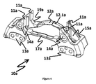
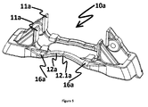
- FIG. 4 and Figure 5 Views of the carrier in current practice are shown in Figure 4 and Figure 5 .
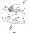
- the detailed comparison of the carrier (10) and the carrier in current practice (10a) is shown in Figure 6 .
- the features given in Figure 4 and Figure 6 are described as the carrier in current practice (10a), the abutments in current practice (11a), the outboard bridge in current practice (12a), the outside bridge clamp spot in current practice (12.1a), the mounting flange in current practice (13a), the guide sleeve mounting surface in current practice (14a), the mitigation gaps in current practice (15a), inboard/outboard bridge links in current practice (16a), the inboard bridge in current practice (17a), the side sections in current practice (18a) and the abutment transition in current practice (19a).
- the mounting flange (13) on the carrier (10) shown in Figure 2 has less surface area than the mounting flange in practice (13a) on the carrier in practice (10a) shown in Figure 4 .
- the surface boundary shape is not smooth on the mounting flange in practice (13a).
- the mounting flange (13) surface has smooth boundary shape.
- the strenght is reduced in the current practise because of the outboard bridge clamp spot (12.1a) on the outboard bridge (12a).
- the outboard bridge flat clamp surface (12.1) is created instead of the outboard bridge clamp spot in current practice (12.1a) on the outboard bridge (12).
- the strenght is increased.
- the cross section area of the inboard bridge (17) is increased near the mounting flange (13) in the invention. Also, material is removed from the centre of inboard bridge (17). Thus, the stress concentration sections are decreased and cross-sectional variation is softened without adding more material.
- Mitigation gaps in the invention decrease the weight and increase casting surface area of carrier without strenght reduction by enlargement of mitigation gap size in comparison with current practice (15a).
- triangular faces (11.1) are formed on abutments (11), to reduce weight, to decrease casting and machining cost of the carrier.
Landscapes
- Engineering & Computer Science (AREA)
- General Engineering & Computer Science (AREA)
- Mechanical Engineering (AREA)
- Braking Arrangements (AREA)
Applications Claiming Priority (1)
| Application Number | Priority Date | Filing Date | Title |
|---|---|---|---|
| TR201209143A TR201209143A2 (enExample) | 2012-08-06 | 2012-08-06 |
Publications (1)
| Publication Number | Publication Date |
|---|---|
| EP2767726A1 true EP2767726A1 (en) | 2014-08-20 |
Family
ID=49322128
Family Applications (1)
| Application Number | Title | Priority Date | Filing Date |
|---|---|---|---|
| EP13004689.9A Withdrawn EP2767726A1 (en) | 2012-08-06 | 2013-09-27 | Innovation at trailer disc brake carriers |
Country Status (2)
| Country | Link |
|---|---|
| EP (1) | EP2767726A1 (enExample) |
| TR (1) | TR201209143A2 (enExample) |
Cited By (4)
| Publication number | Priority date | Publication date | Assignee | Title |
|---|---|---|---|---|
| DE102014113521A1 (de) * | 2014-09-19 | 2016-03-24 | Knorr-Bremse Systeme für Nutzfahrzeuge GmbH | Bremsträger einer Scheibenbremse und Anordnung eines Bremsträgers einer Scheibenbremse an einer Fahrzeugachse |
| DE102015108665A1 (de) * | 2015-06-02 | 2016-12-08 | Knorr-Bremse Systeme für Nutzfahrzeuge GmbH | Bremsträger für eine Scheibenbremse |
| WO2017060514A1 (de) * | 2015-10-09 | 2017-04-13 | Knorr-Bremse Systeme für Nutzfahrzeuge GmbH | Scheibenbremse für ein nutzfahrzeug |
| EP2895763B1 (de) | 2012-09-17 | 2018-05-09 | KNORR-BREMSE Systeme für Nutzfahrzeuge GmbH | Bremsträger |
Families Citing this family (1)
| Publication number | Priority date | Publication date | Assignee | Title |
|---|---|---|---|---|
| TR201209143A2 (enExample) * | 2012-08-06 | 2013-08-22 | Ege Fren Sanayi̇ Ve Ti̇caret Anoni̇m Şi̇rketi̇ |
Citations (6)
| Publication number | Priority date | Publication date | Assignee | Title |
|---|---|---|---|---|
| DE102004002571A1 (de) * | 2003-04-28 | 2004-12-02 | Bpw Bergische Achsen Kg | Bremssattel für eine Scheibenbremse sowie Bremspad für eine Scheibenbremse |
| DE102005059247A1 (de) * | 2005-12-12 | 2007-06-14 | Knorr-Bremse Systeme für Nutzfahrzeuge GmbH | Bremsvorrichtung |
| CN101149086A (zh) | 2006-09-19 | 2008-03-26 | 英国美瑞特重型车制动系统有限公司 | 制动器挂架 |
| US20090078513A1 (en) * | 2007-08-28 | 2009-03-26 | Wabco Radbremsen Gmbh | Brake device, as well as brake carrier and brake caliper, for such brake |
| DE102008027049A1 (de) * | 2008-06-06 | 2009-12-10 | Knorr-Bremse Systeme für Nutzfahrzeuge GmbH | Scheibenbremse für ein Nutzfahrzeug |
| TR201209143A2 (enExample) * | 2012-08-06 | 2013-08-22 | Ege Fren Sanayi̇ Ve Ti̇caret Anoni̇m Şi̇rketi̇ |
-
2012
- 2012-08-06 TR TR201209143A patent/TR201209143A2/xx unknown
-
2013
- 2013-09-27 EP EP13004689.9A patent/EP2767726A1/en not_active Withdrawn
Patent Citations (6)
| Publication number | Priority date | Publication date | Assignee | Title |
|---|---|---|---|---|
| DE102004002571A1 (de) * | 2003-04-28 | 2004-12-02 | Bpw Bergische Achsen Kg | Bremssattel für eine Scheibenbremse sowie Bremspad für eine Scheibenbremse |
| DE102005059247A1 (de) * | 2005-12-12 | 2007-06-14 | Knorr-Bremse Systeme für Nutzfahrzeuge GmbH | Bremsvorrichtung |
| CN101149086A (zh) | 2006-09-19 | 2008-03-26 | 英国美瑞特重型车制动系统有限公司 | 制动器挂架 |
| US20090078513A1 (en) * | 2007-08-28 | 2009-03-26 | Wabco Radbremsen Gmbh | Brake device, as well as brake carrier and brake caliper, for such brake |
| DE102008027049A1 (de) * | 2008-06-06 | 2009-12-10 | Knorr-Bremse Systeme für Nutzfahrzeuge GmbH | Scheibenbremse für ein Nutzfahrzeug |
| TR201209143A2 (enExample) * | 2012-08-06 | 2013-08-22 | Ege Fren Sanayi̇ Ve Ti̇caret Anoni̇m Şi̇rketi̇ |
Cited By (6)
| Publication number | Priority date | Publication date | Assignee | Title |
|---|---|---|---|---|
| EP2895763B1 (de) | 2012-09-17 | 2018-05-09 | KNORR-BREMSE Systeme für Nutzfahrzeuge GmbH | Bremsträger |
| DE102014113521A1 (de) * | 2014-09-19 | 2016-03-24 | Knorr-Bremse Systeme für Nutzfahrzeuge GmbH | Bremsträger einer Scheibenbremse und Anordnung eines Bremsträgers einer Scheibenbremse an einer Fahrzeugachse |
| DE102015108665A1 (de) * | 2015-06-02 | 2016-12-08 | Knorr-Bremse Systeme für Nutzfahrzeuge GmbH | Bremsträger für eine Scheibenbremse |
| WO2017060514A1 (de) * | 2015-10-09 | 2017-04-13 | Knorr-Bremse Systeme für Nutzfahrzeuge GmbH | Scheibenbremse für ein nutzfahrzeug |
| US10738844B2 (en) | 2015-10-09 | 2020-08-11 | Knorr-Bremse Systeme Fuer Nutzfahrzeuge Gmbh | Disc brake for a utility vehicle |
| US10801565B2 (en) | 2015-10-09 | 2020-10-13 | Knorr-Bremse Systeme Fuer Nutzfahrzeuge Gmbh | Disc brake for a utility vehicle, and brake pad set |
Also Published As
| Publication number | Publication date |
|---|---|
| TR201209143A2 (enExample) | 2013-08-22 |
Similar Documents
| Publication | Publication Date | Title |
|---|---|---|
| EP2767726A1 (en) | Innovation at trailer disc brake carriers | |
| EP1903242B1 (en) | A brake carrier | |
| CN106795930B (zh) | 具有双独立致动器的电子驻车制动器 | |
| CN103946579A (zh) | 盘式制动器卡钳本体 | |
| CN103016578A (zh) | 轨道车辆用制动盘及轨道车辆 | |
| US20100176651A1 (en) | Vehicle wheel assembly and system | |
| CN104029724A (zh) | 一种带循环球转向机构麦弗逊独立悬架前轴总成 | |
| CN201095358Y (zh) | 断开式轮边减速驱动桥装配盘式制动器 | |
| AU2015276964A1 (en) | Reduced-diameter brake rotor for heavy-duty vehicles | |
| CN204712790U (zh) | 盘式前桥 | |
| CN108081865A (zh) | 一种组合式车轮 | |
| CN106585273A (zh) | 一种汽车轮毂总成 | |
| US20180045259A1 (en) | Anchor Bracket For Use In A Disc Brake Assembly, Disc Brake Assembly Including Such An Anchor Bracket And Method For Producing Such An Anchor Bracket | |
| CN206520598U (zh) | 一种自增力式车辆应急制动装置 | |
| CN106494373A (zh) | 一种自增力式车辆应急制动装置 | |
| CN201217433Y (zh) | 制动盘保护板及四轮摩托车的转向节组合 | |
| CN204061662U (zh) | 一种改进的粉末冶金闸瓦 | |
| CN203728363U (zh) | 具有去应力结构的天轮轮体 | |
| CN202782506U (zh) | 一种整体式提升桥轴头 | |
| CN101788027A (zh) | 一种汽车盘式制动器 | |
| CN201951484U (zh) | 转向架轴装式盘型制动装置 | |
| CN201566689U (zh) | 油刹管式大落差前桥 | |
| CN201196229Y (zh) | 一种重型车用制动盘 | |
| JP6660216B2 (ja) | ブレーキ支持部材及びこれを備えるブレーキ装置 | |
| CN212373345U (zh) | 一种盘式制动弯轴 |
Legal Events
| Date | Code | Title | Description |
|---|---|---|---|
| PUAI | Public reference made under article 153(3) epc to a published international application that has entered the european phase |
Free format text: ORIGINAL CODE: 0009012 |
|
| 17P | Request for examination filed |
Effective date: 20130927 |
|
| AK | Designated contracting states |
Kind code of ref document: A1 Designated state(s): AL AT BE BG CH CY CZ DE DK EE ES FI FR GB GR HR HU IE IS IT LI LT LU LV MC MK MT NL NO PL PT RO RS SE SI SK SM TR |
|
| AX | Request for extension of the european patent |
Extension state: BA ME |
|
| STAA | Information on the status of an ep patent application or granted ep patent |
Free format text: STATUS: THE APPLICATION IS DEEMED TO BE WITHDRAWN |
|
| 18D | Application deemed to be withdrawn |
Effective date: 20150221 |