EP2767440A1 - Device for protecting a camera for a road vehicle for transporting goods - Google Patents
Device for protecting a camera for a road vehicle for transporting goods Download PDFInfo
- Publication number
- EP2767440A1 EP2767440A1 EP20140154943 EP14154943A EP2767440A1 EP 2767440 A1 EP2767440 A1 EP 2767440A1 EP 20140154943 EP20140154943 EP 20140154943 EP 14154943 A EP14154943 A EP 14154943A EP 2767440 A1 EP2767440 A1 EP 2767440A1
- Authority
- EP
- European Patent Office
- Prior art keywords
- face
- protuberance
- deflecting
- vehicle
- end edges
- Prior art date
- Legal status (The legal status is an assumption and is not a legal conclusion. Google has not performed a legal analysis and makes no representation as to the accuracy of the status listed.)
- Granted
Links
Images


Classifications
-
- B—PERFORMING OPERATIONS; TRANSPORTING
- B60—VEHICLES IN GENERAL
- B60R—VEHICLES, VEHICLE FITTINGS, OR VEHICLE PARTS, NOT OTHERWISE PROVIDED FOR
- B60R11/00—Arrangements for holding or mounting articles, not otherwise provided for
- B60R11/04—Mounting of cameras operative during drive; Arrangement of controls thereof relative to the vehicle
Definitions
- the present invention relates to the field of vehicle shooting means for reducing blind spots, that is to say the fields of vision inaccessible to the driver of the vehicle.
- the present invention relates to a device for protecting a body image means intended to be mounted on the chassis of a road transport vehicle such as a truck, a semitrailer, a trailer or a carrier.
- the body may for example be a refrigerated body.
- Such means of shooting are generally called indirect vision systems and are constituted for example by cameras.
- a road freight transport vehicle may be equipped with cameras mounted on the opposite vertical sides and on the rear face of the body as well as at the front of the vehicle cabin to allow shooting around the vehicle.
- the cameras are associated with a monitor or monitor located inside the cabin. This screen allows the driver to ensure, for example during maneuvers, the absence of objects or other road users in the blind spots.
- the side cameras attached to the vertical sides of the body can observe the lower sides of the road laterally on both sides of the vehicle. For this purpose, these cameras are protruding from the vertical sides of the body. Side cameras are therefore particularly exposed to shocks during vehicle travel or during maneuvers, for example against signs or billboards, buildings, trees, etc. Such shocks can cause the destruction of cameras or damage to the vertical sides of the body.
- the present invention aims to remedy these disadvantages.
- the present invention aims to provide a device for protecting a means of shooting for bodywork of a road vehicle for the transport of goods.
- the present invention also aims to provide a protection device particularly easy to manufacture, mount and economic.
- the device for protecting a road vehicle bodywork vehicle body comprises a fairing intended to be fixed to the bodywork and provided with a fixing base comprising a first interior face. intended to be oriented on the side of the bodywork and a second opposite outer face delimited longitudinally by two opposite lateral end edges, and a protrusion protruding from said outer face and able to protect against shock the means taken views when moving the vehicle in at least one direction of travel.
- the protuberance comprises at least one outer deflecting face of concave or planar shape having at least one slope directed towards one of the lateral end edges delimiting the outer face of the mounting base.
- a concave or flat shape for said deflecting face facilitates the sliding of objects outside the device along the protuberance of the fairing.
- the progressiveness of the slope of the deflecting face is increased and the forces generated by the friction of the external objects are further limited.
- the inner face of the fixing base is flat and said slope of the outer deflecting face is inclined with respect to the inner face.
- the outer deflecting face may advantageously be connected to the outer face of the mounting base, in particular tangentially.
- the outer deflecting face may be connected to the outer face adjacent one of the lateral end edges delimiting the outer face of the attachment base.
- the protuberance comprises two outer deflector faces arranged longitudinally on either side of a distal portion of said protuberance.
- the deflecting faces may be symmetrical with respect to each other by considering a vertical plane passing through said distal portion.
- the protuberance defines at least partially a housing inside which is intended to be housed the means of shooting.
- the protuberance comprises a single deflecting face which is extended, at a distal portion, by one of the lateral end edges delimiting the outer face of the attachment base, said edge being dimensioned to extend laterally beyond the means of shooting and intended to be longitudinally opposite said means.
- the shroud may advantageously be made of a metallic material, in particular steel or aluminum.
- the invention also relates to a body for a road transport vehicle comprising vertical sides, a floor and a ceiling defining an interior space, a finishing piece attached to the upper end of each vertical flank, at least one means of catch views and at least one protective device fixed to the finishing piece of the associated vertical sidewall or fixed between two successive sections of the finishing piece on the associated vertical sidewall.
- a road transport vehicle 10 comprising a frame 12 extending longitudinally and supported by wheels and a body 14 mounted on the frame.
- the bodywork 14 comprises two opposite vertical flanks 16 extending longitudinally, a ceiling 18, a floor 20, a rear face 22 and a front face 24 assembled together to delimit an interior loading space.
- the bodywork 10 also comprises, at the upper end of each sidewall 16, a belt or finishing piece 26 on which are mounted a side camera 28 and a device 30 associated protection.
- the camera 28 is fixed on the finishing piece 26 projecting from the associated sidewall 16 to take pictures down.
- the objective of the camera 28 is oriented towards the ground.
- the camera 28 is oriented along a vertical axis with a fixed angle and can deliver images from the lower side of the road.
- the camera 28 may comprise an outer shell of generally rounded shape which is fixed to the finishing part 26 and inside which are arranged all the optical means for taking pictures.
- the vehicle 10 may also include cameras (not shown) attached to the rear face 22 of the body and the front of the cabin.
- the device 30 is constituted by a protective fairing 32 covering the associated side camera 28.
- the shroud 32 is distinct from the camera 28 and its protective shell.
- the fairing 32 is advantageously made in one piece, for example in a metal material, in particular steel or aluminum.
- the shroud 32 may for example be obtained by stamping or molding.
- the fairing 32 of protection comprises a mounting base 34 provided to be fixed on the finishing part of the vertical sidewall associated, and a protrusion 36 projecting from said base. In the mounted position, the mounting base 34 extends longitudinally and the protrusion 36 is projecting laterally outwardly relative to said base.
- the vertical dimension of the fixing base 34 is equal to that of the end piece of the sidewall.
- the fixing base 34 comprises a front longitudinal plane face 34a extending longitudinally and which is delimited in the longitudinal direction by two opposite end edges 34b, 34c and in the vertical direction by two end edges 34d, 34e longitudinal opposites. In the mounted position, the edges 34b, 34c of the base extend vertically and the edges 34d, 34e extend horizontally and form lower and upper edges.
- the fixing base 34 also comprises an inner face 34f opposite to the outer face 34a in the transverse direction and extending longitudinally.
- the inner face 34f is provided to be oriented on the side of the body and to bear against the finishing piece of the sidewall. In the exemplary embodiment illustrated, the inner face 34f is flat.
- the protuberance 36 is formed on the outer face 34a of the base and extends longitudinally on said face.
- the protrusion 36 protrudes laterally with respect to the outer face 34a on the opposite side to the inner face 34f.
- the fixing base 34 and the protuberance 36 delimit a concave housing 38 inside which the camera 28 is mounted.
- the housing 38 opens at the level of the inner face 34f of the base to allow the fitting of the fairing 32 around the camera. There is no direct contact between the camera 28 and the housing 38.
- the lateral dimension of the protuberance 36 is greater than that of the camera 28.
- the protuberance 36 extends laterally beyond the camera 28.
- the protrusion 36 comprises two outer deflecting faces 36a, 36b which meet at a distal portion 36c of said protuberance.
- the deflecting faces 36a, 36b are symmetrical with respect to each other by considering a median vertical plane of the protrusion passing through the distal portion 36c.
- the deflecting face 36a, respectively 36b extends longitudinally from the distal portion 36c to the vicinity of the lateral end edge 34b, respectively 34c, of the base being connected tangentially to the outer face 34a in the longitudinal direction.
- the deflecting face 36a, respectively 36b has a concave shape having at all points a slope directed towards the lateral end edge 34b, respectively 34c, and inclined relative to the inner faces 34f and outer 34a of the base.
- the inner face 34f extends along an axis of longitudinal elongation.
- the concave shape of the deflecting face 36a, respectively 36b, has at all points a slope inclined relative to the axis of longitudinal elongation of the inner face 34f.
- the protuberance 36 is delimited vertically by two flat faces 36d lower and 36e upper connecting to the outer face 34a of the nozzle.
- a through-orifice 40 is formed in the thickness of the lower face 36d and opens at the housing 38 inside which the camera 28 is disposed. The orifice 40 allows the images to be taken by the camera 28 on the lower side of the camera. the road.
- the deflector face 36a of the fairing provides a protection of the camera 28 during a movement of the vehicle forward and the deflecting face 36b is provided for the protection of the camera during a recoil. Furthermore, the housing 38 formed on the shroud 32 protects the camera from possible splashes of water, sludge and dust.
- the protrusion 36 of the fairing comprises only the deflector face 36a which is extended, at the distal portion 36c, by a lateral end edge 34g longitudinally delimiting the face outer 34a of the mounting base.
- the end edge 34g is opposite to the end edge 34b and is connected to the inner face 34f of the base.
- the lateral end edge 34g has a lateral dimension greater than that of the camera 28.
- the shroud 32 is offset longitudinally forwards with respect to the camera 28.
- the lateral end edge 34g of the protuberance is facing the camera 28 and extends laterally beyond it.
- the deflector face 36a of the protrusion makes it possible to obtain a protection for the camera during a displacement towards the front of the vehicle.
- the protrusion 36 of the protection device has a wall of constant thickness. It could also be possible to provide such a constant thickness for the wall of the protuberance in the first embodiment.
- the camera 28 and the protective device 30 are fixed on the finishing piece 26, itself fixed on the vertical side of the bodywork.
- the camera 28 and the device 30 can be fixed directly to the vertical sidewall of the bodywork and mounted between two profiles of the finishing part of identical shape and spaced from each other in the longitudinal direction. .
- the protective device 30 then forms an extension of the profiles of the finishing part.
- a protection device for a side camera comprising a protuberance having at least one deflecting face ramp so as to protect the camera against shocks during the movement of the vehicle.
Landscapes
- Engineering & Computer Science (AREA)
- Mechanical Engineering (AREA)
- Fittings On The Vehicle Exterior For Carrying Loads, And Devices For Holding Or Mounting Articles (AREA)
- Body Structure For Vehicles (AREA)
- Closed-Circuit Television Systems (AREA)
Abstract
Description
La présente invention concerne le domaine des moyens de prises de vues pour véhicule destinés à réduire les angles morts, c'est-à-dire les champs de vision inaccessibles pour le conducteur du véhicule.The present invention relates to the field of vehicle shooting means for reducing blind spots, that is to say the fields of vision inaccessible to the driver of the vehicle.
Plus particulièrement, la présente invention concerne un dispositif de protection d'un moyen de prises de vues pour carrosserie destinée à être montée sur le châssis d'un véhicule routier de transport de marchandises tel qu'un camion, une semi-remorque, une remorque ou un porteur. La carrosserie peut par exemple être une carrosserie frigorifique.More particularly, the present invention relates to a device for protecting a body image means intended to be mounted on the chassis of a road transport vehicle such as a truck, a semitrailer, a trailer or a carrier. The body may for example be a refrigerated body.
De tels moyens de prises de vue sont généralement nommés systèmes de vision indirecte et sont constitués par exemple par des caméras.Such means of shooting are generally called indirect vision systems and are constituted for example by cameras.
Un véhicule routier de transport de marchandises peut être équipé de caméras fixées sur les flancs verticaux opposés et sur la face arrière de la carrosserie ainsi qu'à l'avant de la cabine du véhicule pour permettre des prises de vues sur le pourtour du véhicule. Les caméras sont associées à un moniteur ou écran de contrôle situé à l'intérieur de la cabine. Cet écran permet au conducteur de s'assurer, par exemple lors de manoeuvres, de l'absence d'objets ou d'autres usagers de la route dans les angles morts.A road freight transport vehicle may be equipped with cameras mounted on the opposite vertical sides and on the rear face of the body as well as at the front of the vehicle cabin to allow shooting around the vehicle. The cameras are associated with a monitor or monitor located inside the cabin. This screen allows the driver to ensure, for example during maneuvers, the absence of objects or other road users in the blind spots.
Les caméras latérales fixées sur les flancs verticaux de la carrosserie permettent d'observer les bas côtés de la route latéralement de part et d'autre du véhicule. Dans ce but, ces caméras sont en saillie par rapport aux flancs verticaux de la carrosserie. Les caméras latérales sont donc particulièrement exposées aux chocs lors du roulage de véhicule ou lors de manoeuvres, par exemple contre des panneaux de signalisation ou d'affichage, des bâtiments, des arbres, etc. De tels chocs peuvent provoquer la destruction des caméras, voire un endommagement des flancs verticaux de la carrosserie.The side cameras attached to the vertical sides of the body can observe the lower sides of the road laterally on both sides of the vehicle. For this purpose, these cameras are protruding from the vertical sides of the body. Side cameras are therefore particularly exposed to shocks during vehicle travel or during maneuvers, for example against signs or billboards, buildings, trees, etc. Such shocks can cause the destruction of cameras or damage to the vertical sides of the body.
La présente invention vise à remédier à ces inconvénients.The present invention aims to remedy these disadvantages.
Plus particulièrement, la présente invention vise à prévoir un dispositif permettant de protéger un moyen de prises de vues pour carrosserie de véhicule routier de transport de marchandises.More particularly, the present invention aims to provide a device for protecting a means of shooting for bodywork of a road vehicle for the transport of goods.
La présente invention vise également à prévoir un dispositif de protection particulièrement facile à fabriquer, à monter et économique.The present invention also aims to provide a protection device particularly easy to manufacture, mount and economic.
Dans un mode de réalisation, le dispositif de protection d'un moyen de prises de vues pour carrosserie de véhicule routier de transport de marchandises comprend un carénage destiné à être fixé à la carrosserie et pourvu d'une embase de fixation comprenant une première face intérieure destinée à être orientée du côté de la carrosserie et une seconde face extérieure opposée délimitée longitudinalement par deux bords d'extrémité latéraux opposés, et d'une protubérance en saillie par rapport à ladite face extérieure et apte à protéger contre les chocs le moyen de prises de vues lors du déplacement du véhicule selon au moins un sens de déplacement. La protubérance comprend au moins une face déflectrice extérieure de forme concave ou plane présentant au moins une pente dirigée vers un des bords d'extrémité latéraux délimitant la face extérieure de l'embase de fixation.In one embodiment, the device for protecting a road vehicle bodywork vehicle body comprises a fairing intended to be fixed to the bodywork and provided with a fixing base comprising a first interior face. intended to be oriented on the side of the bodywork and a second opposite outer face delimited longitudinally by two opposite lateral end edges, and a protrusion protruding from said outer face and able to protect against shock the means taken views when moving the vehicle in at least one direction of travel. The protuberance comprises at least one outer deflecting face of concave or planar shape having at least one slope directed towards one of the lateral end edges delimiting the outer face of the mounting base.
La prévision d'une forme concave ou plane pour ladite face déflectrice permet de faciliter le glissement d'objets extérieurs au dispositif le long de la protubérance du carénage. En outre, en cas de forme concave, la progressivité de la pente de la face déflectrice est augmentée et on limite encore les efforts engendrés par le frottement des objets extérieurs.The provision of a concave or flat shape for said deflecting face facilitates the sliding of objects outside the device along the protuberance of the fairing. In addition, in the case of a concave shape, the progressiveness of the slope of the deflecting face is increased and the forces generated by the friction of the external objects are further limited.
Dans un mode de réalisation, la face intérieure de l'embase de fixation est plane et ladite pente de la face déflectrice extérieure est inclinée par rapport à la face intérieure.In one embodiment, the inner face of the fixing base is flat and said slope of the outer deflecting face is inclined with respect to the inner face.
La face déflectrice extérieure peut avantageusement se raccorder à la face extérieure de l'embase de fixation, notamment tangentiellement. La face déflectrice extérieure peut se raccorder à la face extérieure au voisinage d'un des bords d'extrémité latéraux délimitant la face extérieure de l'embase de fixation.The outer deflecting face may advantageously be connected to the outer face of the mounting base, in particular tangentially. The outer deflecting face may be connected to the outer face adjacent one of the lateral end edges delimiting the outer face of the attachment base.
Dans un mode de réalisation, la protubérance comprend deux faces déflectrices extérieures disposées longitudinalement de part et d'autre d'une partie distale de ladite protubérance. Les faces déflectrices peuvent être symétriques l'une par rapport à l'autre en considérant un plan vertical passant par ladite partie distale. De préférence, la protubérance délimite au moins en partie un logement à l'intérieur duquel est destiné à être logé le moyen de prises de vues.In one embodiment, the protuberance comprises two outer deflector faces arranged longitudinally on either side of a distal portion of said protuberance. The deflecting faces may be symmetrical with respect to each other by considering a vertical plane passing through said distal portion. Preferably, the protuberance defines at least partially a housing inside which is intended to be housed the means of shooting.
Dans un autre mode de réalisation, la protubérance comprend une unique face déflectrice qui est prolongée, au niveau d'une partie distale, par un des bords d'extrémité latéraux délimitant la face extérieure de l'embase de fixation, ledit bord étant dimensionné pour s'étendre latéralement au-delà du moyen de prises de vues et destiné à être longitudinalement en regard dudit moyen.In another embodiment, the protuberance comprises a single deflecting face which is extended, at a distal portion, by one of the lateral end edges delimiting the outer face of the attachment base, said edge being dimensioned to extend laterally beyond the means of shooting and intended to be longitudinally opposite said means.
Le carénage peut avantageusement être réalisé dans une matière métallique, notamment en acier ou en aluminium.The shroud may advantageously be made of a metallic material, in particular steel or aluminum.
L'invention concerne également une carrosserie pour véhicule routier de transport de marchandises comprenant des flancs verticaux, un plancher et un plafond délimitant un espace intérieur, une pièce de finition fixée à l'extrémité supérieure de chaque flanc vertical, au moins un moyen de prises de vues et au moins un dispositif de protection fixés sur la pièce de finition du flanc vertical associé ou fixés entre deux profilés successifs de la pièce de finition sur le flanc vertical associé.The invention also relates to a body for a road transport vehicle comprising vertical sides, a floor and a ceiling defining an interior space, a finishing piece attached to the upper end of each vertical flank, at least one means of catch views and at least one protective device fixed to the finishing piece of the associated vertical sidewall or fixed between two successive sections of the finishing piece on the associated vertical sidewall.
La présente invention sera mieux comprise à l'étude de la description détaillée de modes de réalisation pris à titre d'exemples nullement limitatifs et illustrés par les dessins annexés, sur lesquels :
- la
figure 1 est une vue de côté d'un véhicule routier selon un premier exemple de réalisation, - la
figure 2 est une vue de détail de lafigure 1 illustrant un dispositif de protection d'une caméra du véhicule, - les
figures 3 et 4 sont des vues partielles de dessus et de l'arrière du véhicule de lafigure 1 illustrant le dispositif de protection, - la
figure 5 est une vue de face du dispositif de protection desfigures 2 à 4 , - les
figures 6 et 7 sont des vues en coupe selon les axes VI-VI et VII-VII de lafigure 5 , - la
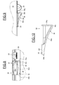
figure 8 est une vue partielle de côté d'un véhicule routier comprenant un dispositif de protection d'une caméra selon un second exemple de réalisation, - la
figure 9 est une vue partielle de dessus du véhicule de lafigure 8 illustrant le dispositif de protection, et - la
figure 10 est une vue en coupe du dispositif de protection desfigures 8 et 9 .
- the
figure 1 is a side view of a road vehicle according to a first embodiment, - the
figure 2 is a detail view of thefigure 1 illustrating a device for protecting a camera of the vehicle, - the
Figures 3 and 4 are partial views from above and from the rear of the vehicle thefigure 1 illustrating the protection device, - the
figure 5 is a front view of the protective device of theFigures 2 to 4 , - the
Figures 6 and 7 are cross-sectional views along lines VI-VI and VII-VII of thefigure 5 , - the
figure 8 is a partial side view of a road vehicle comprising a device for protecting a camera according to a second exemplary embodiment, - the
figure 9 is a partial top view of the vehicle from thefigure 8 illustrating the protective device, and - the
figure 10 is a sectional view of the protective device ofFigures 8 and 9 .
Sur la
Comme cela est illustré sur les
La caméra 28 est fixée sur la pièce de finition 26 en étant en saillie par rapport au flanc 16 associé pour réaliser des prises de vues vers le bas. L'objectif de la caméra 28 est orienté vers le sol. La caméra 28 est orientée selon un axe vertical avec un angle fixe et permet de délivrer des images du bas côté de la route. La caméra 28 peut comprendre une coque extérieure de forme générale arrondie qui est fixée à la pièce de finition 26 et à l'intérieur de laquelle sont disposés l'ensemble des moyens optiques permettant les prises de vues. Le véhicule 10 peut également comprendre des caméras (non représentées) fixées sur la face arrière 22 de la carrosserie et à l'avant de la cabine.The
Comme illustré plus visiblement aux
Le carénage 32 de protection comprend une embase 34 de fixation prévue pour venir se fixer sur la pièce de finition du flanc vertical associé, et une protubérance 36 faisant saillie par rapport à ladite embase. Dans la position montée, l'embase 34 de fixation s'étend longitudinalement et la protubérance 36 est en saillie latéralement vers l'extérieur par rapport à ladite embase. La dimension verticale de l'embase 34 de fixation est égale à celle de la pièce de finition du flanc.The
L'embase 34 de fixation comprend une face extérieure 34a plane frontale s'étendant longitudinalement et qui est délimitée dans le sens longitudinal par deux bords d'extrémité 34b, 34c latéraux opposés et dans le sens vertical par deux bords d'extrémité 34d, 34e longitudinaux opposés. Dans la position montée, les bords 34b, 34c de l'embase s'étendent verticalement et les bords 34d, 34e s'étendent horizontalement et forment des bords inférieur et supérieur. L'embase 34 de fixation comprend également une face intérieure 34f frontale opposée à la face extérieure 34a dans le sens transversal et s'étendant longitudinalement. La face intérieure 34f est prévue pour être orientée du côté de la carrosserie et pour venir en appui contre la pièce de finition du flanc. Dans l'exemple de réalisation illustré, la face intérieure 34f est plane.The
La protubérance 36 est formée sur la face extérieure 34a de l'embase et s'étend longitudinalement sur ladite face. La protubérance 36 fait saillie latéralement par rapport à la face extérieure 34a du côté opposé à la face intérieure 34f. L'embase 34 de fixation et la protubérance 36 délimitent un logement 38 concave à l'intérieur duquel est montée la caméra 28. Le logement 38 débouche au niveau de la face intérieure 34f de l'embase pour permettre le montage du carénage 32 autour de la caméra. Il n'existe aucun contact direct entre la caméra 28 et le logement 38. La dimension latérale de la protubérance 36 est supérieure à celle de la caméra 28. La protubérance 36 s'étend latéralement au-delà de la caméra 28.The
La protubérance 36 comprend deux faces déflectrices 36a, 36b extérieures qui se rejoignent au niveau d'une partie distale 36c de ladite protubérance. Les faces déflectrices 36a, 36b sont symétriques l'une par rapport à l'autre en considérant un plan vertical médian de la protubérance passant par la partie distale 36c. La face déflectrice 36a, respectivement 36b, s'étend longitudinalement de la partie distale 36c jusqu'au voisinage du bord d'extrémité 34b latéral, respectivement 34c, de l'embase en se raccordant tangentiellement à la face extérieure 34a dans le sens longitudinal. La face déflectrice 36a, respectivement 36b, présente une forme concave présentant en tout point une pente dirigée vers le bord d'extrémité 34b latéral, respectivement 34c, et inclinée par rapport aux faces intérieure 34f et extérieure 34a de l'embase. La face intérieure 34f s'étend selon un axe d'allongement longitudinal. La forme concave de la face déflectrice 36a, respectivement 36b, présente en tout point une pente inclinée par rapport à l'axe d'allongement longitudinal de la face intérieure 34f.The
Dans une variante de réalisation, il pourrait être possible de prévoir une face déflectrice 36a, respectivement 36b, plane inclinée avec une pente constante par rapport aux faces intérieure 34f et extérieure 34a de l'embase.In an alternative embodiment, it could be possible to provide a deflecting
La protubérance 36 est délimitée verticalement par deux faces planes 36d inférieure et 36e supérieure se raccordant à la face extérieure 34a de l'embout. Un orifice 40 traversant est ménagé dans l'épaisseur de la face 36d inférieure et débouche au niveau du logement 38 à l'intérieur duquel est disposée la caméra 28. L'orifice 40 permet les prises de vues par la caméra 28 du bas côté de la route.The
Lors d'un déplacement du véhicule vers l'avant, si un objet extérieur vient glisser longitudinalement le long de la face déflectrice 36a du carénage, ladite face déflectrice va modifier l'orientation de l'effort appliqué par ledit objet sur le carénage qui va passer d'une orientation longitudinale à une orientation inclinée par rapport au flanc vertical associé de la carrosserie. Si l'objet percuté est plus rigide que les suspensions du véhicule, l'effort appliqué sur le flanc est transmis jusqu'à ces suspensions pour y être absorbé. Au contraire, si l'objet percuté est plus souple que les suspensions, ledit objet va alors être dévié latéralement vers l'extérieur. Dans les deux cas, le carénage 32 forme un obstacle recouvrant la caméra 28 et permet d'obtenir une protection contre les chocs. La face déflectrice 36a du carénage permet d'obtenir une protection de la caméra 28 lors d'un déplacement du véhicule vers l'avant et la face déflectrice 36b est prévue pour la protection de la caméra lors d'un recul. Par ailleurs, le logement 38 formé sur le carénage 32 permet de protéger la caméra par rapport aux éventuelles projections d'eau, de boues et de poussières.During a movement of the vehicle forward, if an outer object is slid longitudinally along the
L'exemple de réalisation illustré aux
Dans le second exemple de réalisation décrit, la protubérance 36 du dispositif de protection présente une paroi d'épaisseur constante. Il pourrait également être possible de prévoir une telle épaisseur constante pour la paroi de la protubérance dans le premier exemple de réalisation.In the second embodiment described, the
Dans les deux exemples de réalisation illustrés, la caméra 28 et le dispositif 30 de protection sont fixés sur la pièce de finition 26, elle-même fixée sur le flanc vertical de la carrosserie. Dans une variante de réalisation, la caméra 28 et le dispositif 30 peuvent être fixés directement sur le flanc vertical de la carrosserie et montés entre deux profilés de la pièce de finition de forme identique et espacés l'un de l'autre dans le sens longitudinal. Le dispositif 30 de protection forme alors un prolongement des profilés de la pièce de finition.In the two exemplary embodiments illustrated, the
Grâce à l'invention, on dispose d'un dispositif de protection pour une caméra latérale comprenant une protubérance ayant au moins une face déflectrice formant rampe de sorte à protéger la caméra contre les chocs lors du déplacement du véhicule.Thanks to the invention, there is a protection device for a side camera comprising a protuberance having at least one deflecting face ramp so as to protect the camera against shocks during the movement of the vehicle.
Claims (11)
Applications Claiming Priority (1)
| Application Number | Priority Date | Filing Date | Title |
|---|---|---|---|
| FR1351389A FR3002195B1 (en) | 2013-02-19 | 2013-02-19 | DEVICE FOR PROTECTING A CAMERA FOR A ROAD VEHICLE FOR CARRYING GOODS |
Publications (2)
| Publication Number | Publication Date |
|---|---|
| EP2767440A1 true EP2767440A1 (en) | 2014-08-20 |
| EP2767440B1 EP2767440B1 (en) | 2015-10-28 |
Family
ID=48521196
Family Applications (1)
| Application Number | Title | Priority Date | Filing Date |
|---|---|---|---|
| EP14154943.6A Not-in-force EP2767440B1 (en) | 2013-02-19 | 2014-02-13 | Device for protecting a camera for a road vehicle for transporting goods |
Country Status (3)
| Country | Link |
|---|---|
| EP (1) | EP2767440B1 (en) |
| ES (1) | ES2558835T3 (en) |
| FR (1) | FR3002195B1 (en) |
Citations (4)
| Publication number | Priority date | Publication date | Assignee | Title |
|---|---|---|---|---|
| JPH09202181A (en) * | 1996-01-26 | 1997-08-05 | Ichikoh Ind Ltd | Monitoring camera |
| US20080173816A1 (en) * | 2005-11-09 | 2008-07-24 | Jonathan Everett | Aviation vision apparatus |
| WO2009037819A1 (en) * | 2007-09-18 | 2009-03-26 | Eitaro Terakawa | Protective structure for imaging device |
| JP2010171499A (en) * | 2009-01-20 | 2010-08-05 | Eitaro Terakawa | Protection structure of imaging device |
-
2013
- 2013-02-19 FR FR1351389A patent/FR3002195B1/en not_active Expired - Fee Related
-
2014
- 2014-02-13 ES ES14154943.6T patent/ES2558835T3/en active Active
- 2014-02-13 EP EP14154943.6A patent/EP2767440B1/en not_active Not-in-force
Patent Citations (4)
| Publication number | Priority date | Publication date | Assignee | Title |
|---|---|---|---|---|
| JPH09202181A (en) * | 1996-01-26 | 1997-08-05 | Ichikoh Ind Ltd | Monitoring camera |
| US20080173816A1 (en) * | 2005-11-09 | 2008-07-24 | Jonathan Everett | Aviation vision apparatus |
| WO2009037819A1 (en) * | 2007-09-18 | 2009-03-26 | Eitaro Terakawa | Protective structure for imaging device |
| JP2010171499A (en) * | 2009-01-20 | 2010-08-05 | Eitaro Terakawa | Protection structure of imaging device |
Also Published As
| Publication number | Publication date |
|---|---|
| FR3002195A1 (en) | 2014-08-22 |
| FR3002195B1 (en) | 2016-10-28 |
| ES2558835T3 (en) | 2016-02-09 |
| EP2767440B1 (en) | 2015-10-28 |
Similar Documents
| Publication | Publication Date | Title |
|---|---|---|
| FR3010037A1 (en) | VEHICLE COMPRISING A DEFLECTOR DEVICE AND DEFLECTING DEVICE | |
| WO2020169371A1 (en) | Protective device for a motor vehicle member mounted below a body shell | |
| EP3732080B1 (en) | Motor vehicle front impact absorption device comprising a pivoting air deflector and a deformable impact absorber connected to one another | |
| EP2767440B1 (en) | Device for protecting a camera for a road vehicle for transporting goods | |
| FR3034383B1 (en) | ANTI-CAPOTAGE SYSTEM FOR A MOTOR VEHICLE | |
| EP3765337B1 (en) | Sensor support for a vehicle and method of mounting | |
| EP3885201B1 (en) | Vehicle provided with a secure reverse sensor | |
| EP0011000B1 (en) | Guiding device for the lateral wings of a bumper on an automotive vehicle | |
| FR3056176A1 (en) | ARRANGEMENT FOR FASTENING A SCREEN FOR PROTECTING A DETECTION DEVICE IN A MOTOR VEHICLE | |
| EP2130717B1 (en) | System for limiting the damage that can be caused, in the event of a crash, by an optical unit to at least one unit of an automobile | |
| EP2915696B1 (en) | Removable universal strap winder for vehicle | |
| FR2992621A1 (en) | MOTOR VEHICLE COMPRISING AN ADDITIONAL REINFORCEMENT PART CAPABLE OF GUIDING THE DEFORMATION OF THE CENTRAL PILLAR STRUCTURE IN THE EVENT OF LATERAL SHOCK | |
| FR2978413A1 (en) | FRONT FACE MODULE OF VEHICLE, IN PARTICULAR MOTOR VEHICLE | |
| EP2942240A1 (en) | Garnish element for a motor vehicle door threshold | |
| FR2980439A1 (en) | System for fixing seat belt retractor on car's body, has retractor support including top part fixed on upright on sides of retractor and bottom part free relative to upright, where top part is more separated from longeron than bottom part | |
| FR3087182A1 (en) | BODY OF A ROAD VEHICLE FOR THE TRANSPORT OF GOODS PROVIDED WITH A REAR UPPER DEFLECTOR | |
| FR2681019A1 (en) | Rear light for motor vehicle with integrated reserve of screen washer | |
| EP3737575B1 (en) | Central rail housing of a sliding door of a motor vehicle | |
| FR3117429A1 (en) | BUMPER DEVICE WITH INTEGRATED ABSORBER AND VEHICLE COMPRISING SUCH A DEVICE | |
| FR3103455A1 (en) | Vehicle fitted with an optimized instrument panel mounting device | |
| FR2807991A1 (en) | Lightweight modular car trailer has supports with slideways on at least one side of body to allow side panel to be fitted by vertical movement | |
| FR3047454A1 (en) | PROTECTIVE PANEL FOR MOTOR VEHICLE BODYWORK WITH PLATING SURFACE | |
| FR3048643B1 (en) | SHUTTER DEVICE FOR MOTOR VEHICLE AND FRONT PANEL MODULE SUPPORT COMPRISING SAID SHUTTERING DEVICE | |
| FR3082470A1 (en) | SYSTEM FOR SECURING A LIFT TRUCK WITHIN A BODY OF A ROAD VEHICLE FOR THE TRANSPORT OF GOODS | |
| FR3139787A1 (en) | Device forming a step of a motor vehicle |
Legal Events
| Date | Code | Title | Description |
|---|---|---|---|
| PUAI | Public reference made under article 153(3) epc to a published international application that has entered the european phase |
Free format text: ORIGINAL CODE: 0009012 |
|
| 17P | Request for examination filed |
Effective date: 20140213 |
|
| AK | Designated contracting states |
Kind code of ref document: A1 Designated state(s): AL AT BE BG CH CY CZ DE DK EE ES FI FR GB GR HR HU IE IS IT LI LT LU LV MC MK MT NL NO PL PT RO RS SE SI SK SM TR |
|
| AX | Request for extension of the european patent |
Extension state: BA ME |
|
| R17P | Request for examination filed (corrected) |
Effective date: 20150121 |
|
| GRAP | Despatch of communication of intention to grant a patent |
Free format text: ORIGINAL CODE: EPIDOSNIGR1 |
|
| RIC1 | Information provided on ipc code assigned before grant |
Ipc: B60R 11/04 20060101AFI20150505BHEP |
|
| INTG | Intention to grant announced |
Effective date: 20150526 |
|
| GRAS | Grant fee paid |
Free format text: ORIGINAL CODE: EPIDOSNIGR3 |
|
| GRAA | (expected) grant |
Free format text: ORIGINAL CODE: 0009210 |
|
| AK | Designated contracting states |
Kind code of ref document: B1 Designated state(s): AL AT BE BG CH CY CZ DE DK EE ES FI FR GB GR HR HU IE IS IT LI LT LU LV MC MK MT NL NO PL PT RO RS SE SI SK SM TR |
|
| REG | Reference to a national code |
Ref country code: GB Ref legal event code: FG4D Free format text: NOT ENGLISH |
|
| REG | Reference to a national code |
Ref country code: CH Ref legal event code: EP |
|
| REG | Reference to a national code |
Ref country code: AT Ref legal event code: REF Ref document number: 757744 Country of ref document: AT Kind code of ref document: T Effective date: 20151115 |
|
| REG | Reference to a national code |
Ref country code: IE Ref legal event code: FG4D Free format text: LANGUAGE OF EP DOCUMENT: FRENCH |
|
| REG | Reference to a national code |
Ref country code: DE Ref legal event code: R096 Ref document number: 602014000372 Country of ref document: DE |
|
| REG | Reference to a national code |
Ref country code: FR Ref legal event code: PLFP Year of fee payment: 3 |
|
| REG | Reference to a national code |
Ref country code: ES Ref legal event code: FG2A Ref document number: 2558835 Country of ref document: ES Kind code of ref document: T3 Effective date: 20160209 |
|
| REG | Reference to a national code |
Ref country code: LT Ref legal event code: MG4D |
|
| REG | Reference to a national code |
Ref country code: NL Ref legal event code: MP Effective date: 20151028 |
|
| REG | Reference to a national code |
Ref country code: AT Ref legal event code: MK05 Ref document number: 757744 Country of ref document: AT Kind code of ref document: T Effective date: 20151028 |
|
| PG25 | Lapsed in a contracting state [announced via postgrant information from national office to epo] |
Ref country code: NL Free format text: LAPSE BECAUSE OF FAILURE TO SUBMIT A TRANSLATION OF THE DESCRIPTION OR TO PAY THE FEE WITHIN THE PRESCRIBED TIME-LIMIT Effective date: 20151028 Ref country code: IS Free format text: LAPSE BECAUSE OF FAILURE TO SUBMIT A TRANSLATION OF THE DESCRIPTION OR TO PAY THE FEE WITHIN THE PRESCRIBED TIME-LIMIT Effective date: 20160228 Ref country code: LT Free format text: LAPSE BECAUSE OF FAILURE TO SUBMIT A TRANSLATION OF THE DESCRIPTION OR TO PAY THE FEE WITHIN THE PRESCRIBED TIME-LIMIT Effective date: 20151028 Ref country code: NO Free format text: LAPSE BECAUSE OF FAILURE TO SUBMIT A TRANSLATION OF THE DESCRIPTION OR TO PAY THE FEE WITHIN THE PRESCRIBED TIME-LIMIT Effective date: 20160128 Ref country code: HR Free format text: LAPSE BECAUSE OF FAILURE TO SUBMIT A TRANSLATION OF THE DESCRIPTION OR TO PAY THE FEE WITHIN THE PRESCRIBED TIME-LIMIT Effective date: 20151028 |
|
| PGFP | Annual fee paid to national office [announced via postgrant information from national office to epo] |
Ref country code: DE Payment date: 20160212 Year of fee payment: 3 Ref country code: ES Payment date: 20160301 Year of fee payment: 3 |
|
| PG25 | Lapsed in a contracting state [announced via postgrant information from national office to epo] |
Ref country code: SE Free format text: LAPSE BECAUSE OF FAILURE TO SUBMIT A TRANSLATION OF THE DESCRIPTION OR TO PAY THE FEE WITHIN THE PRESCRIBED TIME-LIMIT Effective date: 20151028 Ref country code: RS Free format text: LAPSE BECAUSE OF FAILURE TO SUBMIT A TRANSLATION OF THE DESCRIPTION OR TO PAY THE FEE WITHIN THE PRESCRIBED TIME-LIMIT Effective date: 20151028 Ref country code: PL Free format text: LAPSE BECAUSE OF FAILURE TO SUBMIT A TRANSLATION OF THE DESCRIPTION OR TO PAY THE FEE WITHIN THE PRESCRIBED TIME-LIMIT Effective date: 20151028 Ref country code: AT Free format text: LAPSE BECAUSE OF FAILURE TO SUBMIT A TRANSLATION OF THE DESCRIPTION OR TO PAY THE FEE WITHIN THE PRESCRIBED TIME-LIMIT Effective date: 20151028 Ref country code: BE Free format text: LAPSE BECAUSE OF NON-PAYMENT OF DUE FEES Effective date: 20160229 Ref country code: GR Free format text: LAPSE BECAUSE OF FAILURE TO SUBMIT A TRANSLATION OF THE DESCRIPTION OR TO PAY THE FEE WITHIN THE PRESCRIBED TIME-LIMIT Effective date: 20160129 Ref country code: FI Free format text: LAPSE BECAUSE OF FAILURE TO SUBMIT A TRANSLATION OF THE DESCRIPTION OR TO PAY THE FEE WITHIN THE PRESCRIBED TIME-LIMIT Effective date: 20151028 Ref country code: PT Free format text: LAPSE BECAUSE OF FAILURE TO SUBMIT A TRANSLATION OF THE DESCRIPTION OR TO PAY THE FEE WITHIN THE PRESCRIBED TIME-LIMIT Effective date: 20160229 Ref country code: LV Free format text: LAPSE BECAUSE OF FAILURE TO SUBMIT A TRANSLATION OF THE DESCRIPTION OR TO PAY THE FEE WITHIN THE PRESCRIBED TIME-LIMIT Effective date: 20151028 |
|
| PGFP | Annual fee paid to national office [announced via postgrant information from national office to epo] |
Ref country code: FR Payment date: 20160120 Year of fee payment: 3 |
|
| PG25 | Lapsed in a contracting state [announced via postgrant information from national office to epo] |
Ref country code: CZ Free format text: LAPSE BECAUSE OF FAILURE TO SUBMIT A TRANSLATION OF THE DESCRIPTION OR TO PAY THE FEE WITHIN THE PRESCRIBED TIME-LIMIT Effective date: 20151028 |
|
| REG | Reference to a national code |
Ref country code: DE Ref legal event code: R097 Ref document number: 602014000372 Country of ref document: DE |
|
| PG25 | Lapsed in a contracting state [announced via postgrant information from national office to epo] |
Ref country code: RO Free format text: LAPSE BECAUSE OF FAILURE TO SUBMIT A TRANSLATION OF THE DESCRIPTION OR TO PAY THE FEE WITHIN THE PRESCRIBED TIME-LIMIT Effective date: 20151028 Ref country code: SM Free format text: LAPSE BECAUSE OF FAILURE TO SUBMIT A TRANSLATION OF THE DESCRIPTION OR TO PAY THE FEE WITHIN THE PRESCRIBED TIME-LIMIT Effective date: 20151028 Ref country code: EE Free format text: LAPSE BECAUSE OF FAILURE TO SUBMIT A TRANSLATION OF THE DESCRIPTION OR TO PAY THE FEE WITHIN THE PRESCRIBED TIME-LIMIT Effective date: 20151028 Ref country code: SK Free format text: LAPSE BECAUSE OF FAILURE TO SUBMIT A TRANSLATION OF THE DESCRIPTION OR TO PAY THE FEE WITHIN THE PRESCRIBED TIME-LIMIT Effective date: 20151028 Ref country code: DK Free format text: LAPSE BECAUSE OF FAILURE TO SUBMIT A TRANSLATION OF THE DESCRIPTION OR TO PAY THE FEE WITHIN THE PRESCRIBED TIME-LIMIT Effective date: 20151028 |
|
| PLBE | No opposition filed within time limit |
Free format text: ORIGINAL CODE: 0009261 |
|
| STAA | Information on the status of an ep patent application or granted ep patent |
Free format text: STATUS: NO OPPOSITION FILED WITHIN TIME LIMIT |
|
| PG25 | Lapsed in a contracting state [announced via postgrant information from national office to epo] |
Ref country code: MC Free format text: LAPSE BECAUSE OF FAILURE TO SUBMIT A TRANSLATION OF THE DESCRIPTION OR TO PAY THE FEE WITHIN THE PRESCRIBED TIME-LIMIT Effective date: 20151028 Ref country code: LU Free format text: LAPSE BECAUSE OF FAILURE TO SUBMIT A TRANSLATION OF THE DESCRIPTION OR TO PAY THE FEE WITHIN THE PRESCRIBED TIME-LIMIT Effective date: 20160213 |
|
| 26N | No opposition filed |
Effective date: 20160729 |
|
| PG25 | Lapsed in a contracting state [announced via postgrant information from national office to epo] |
Ref country code: SI Free format text: LAPSE BECAUSE OF FAILURE TO SUBMIT A TRANSLATION OF THE DESCRIPTION OR TO PAY THE FEE WITHIN THE PRESCRIBED TIME-LIMIT Effective date: 20151028 |
|
| REG | Reference to a national code |
Ref country code: IE Ref legal event code: MM4A |
|
| PG25 | Lapsed in a contracting state [announced via postgrant information from national office to epo] |
Ref country code: IE Free format text: LAPSE BECAUSE OF NON-PAYMENT OF DUE FEES Effective date: 20160213 |
|
| PGFP | Annual fee paid to national office [announced via postgrant information from national office to epo] |
Ref country code: IT Payment date: 20170228 Year of fee payment: 4 |
|
| PG25 | Lapsed in a contracting state [announced via postgrant information from national office to epo] |
Ref country code: MT Free format text: LAPSE BECAUSE OF FAILURE TO SUBMIT A TRANSLATION OF THE DESCRIPTION OR TO PAY THE FEE WITHIN THE PRESCRIBED TIME-LIMIT Effective date: 20151028 |
|
| REG | Reference to a national code |
Ref country code: DE Ref legal event code: R119 Ref document number: 602014000372 Country of ref document: DE |
|
| REG | Reference to a national code |
Ref country code: CH Ref legal event code: PL |
|
| PG25 | Lapsed in a contracting state [announced via postgrant information from national office to epo] |
Ref country code: CH Free format text: LAPSE BECAUSE OF NON-PAYMENT OF DUE FEES Effective date: 20170228 Ref country code: LI Free format text: LAPSE BECAUSE OF NON-PAYMENT OF DUE FEES Effective date: 20170228 |
|
| REG | Reference to a national code |
Ref country code: FR Ref legal event code: ST Effective date: 20171031 |
|
| PG25 | Lapsed in a contracting state [announced via postgrant information from national office to epo] |
Ref country code: FR Free format text: LAPSE BECAUSE OF NON-PAYMENT OF DUE FEES Effective date: 20170228 Ref country code: DE Free format text: LAPSE BECAUSE OF NON-PAYMENT OF DUE FEES Effective date: 20170901 |
|
| PG25 | Lapsed in a contracting state [announced via postgrant information from national office to epo] |
Ref country code: CY Free format text: LAPSE BECAUSE OF FAILURE TO SUBMIT A TRANSLATION OF THE DESCRIPTION OR TO PAY THE FEE WITHIN THE PRESCRIBED TIME-LIMIT Effective date: 20151028 Ref country code: HU Free format text: LAPSE BECAUSE OF FAILURE TO SUBMIT A TRANSLATION OF THE DESCRIPTION OR TO PAY THE FEE WITHIN THE PRESCRIBED TIME-LIMIT; INVALID AB INITIO Effective date: 20140213 |
|
| REG | Reference to a national code |
Ref country code: ES Ref legal event code: FD2A Effective date: 20180625 |
|
| PG25 | Lapsed in a contracting state [announced via postgrant information from national office to epo] |
Ref country code: MK Free format text: LAPSE BECAUSE OF FAILURE TO SUBMIT A TRANSLATION OF THE DESCRIPTION OR TO PAY THE FEE WITHIN THE PRESCRIBED TIME-LIMIT Effective date: 20151028 Ref country code: TR Free format text: LAPSE BECAUSE OF FAILURE TO SUBMIT A TRANSLATION OF THE DESCRIPTION OR TO PAY THE FEE WITHIN THE PRESCRIBED TIME-LIMIT Effective date: 20151028 |
|
| PG25 | Lapsed in a contracting state [announced via postgrant information from national office to epo] |
Ref country code: BG Free format text: LAPSE BECAUSE OF FAILURE TO SUBMIT A TRANSLATION OF THE DESCRIPTION OR TO PAY THE FEE WITHIN THE PRESCRIBED TIME-LIMIT Effective date: 20151028 Ref country code: ES Free format text: LAPSE BECAUSE OF NON-PAYMENT OF DUE FEES Effective date: 20170214 |
|
| GBPC | Gb: european patent ceased through non-payment of renewal fee |
Effective date: 20180213 |
|
| PG25 | Lapsed in a contracting state [announced via postgrant information from national office to epo] |
Ref country code: AL Free format text: LAPSE BECAUSE OF FAILURE TO SUBMIT A TRANSLATION OF THE DESCRIPTION OR TO PAY THE FEE WITHIN THE PRESCRIBED TIME-LIMIT Effective date: 20151028 |
|
| PG25 | Lapsed in a contracting state [announced via postgrant information from national office to epo] |
Ref country code: GB Free format text: LAPSE BECAUSE OF NON-PAYMENT OF DUE FEES Effective date: 20180213 Ref country code: IT Free format text: LAPSE BECAUSE OF NON-PAYMENT OF DUE FEES Effective date: 20180213 |
|
| P01 | Opt-out of the competence of the unified patent court (upc) registered |
Effective date: 20230525 |