EP2765327B1 - Universelles Anschlagrohr - Google Patents
Universelles Anschlagrohr Download PDFInfo
- Publication number
- EP2765327B1 EP2765327B1 EP14000456.5A EP14000456A EP2765327B1 EP 2765327 B1 EP2765327 B1 EP 2765327B1 EP 14000456 A EP14000456 A EP 14000456A EP 2765327 B1 EP2765327 B1 EP 2765327B1
- Authority
- EP
- European Patent Office
- Prior art keywords
- strut
- cylinder
- tube
- locking tube
- assembly
- Prior art date
- Legal status (The legal status is an assumption and is not a legal conclusion. Google has not performed a legal analysis and makes no representation as to the accuracy of the status listed.)
- Active
Links
Images


Classifications
-
- E—FIXED CONSTRUCTIONS
- E05—LOCKS; KEYS; WINDOW OR DOOR FITTINGS; SAFES
- E05F—DEVICES FOR MOVING WINGS INTO OPEN OR CLOSED POSITION; CHECKS FOR WINGS; WING FITTINGS NOT OTHERWISE PROVIDED FOR, CONCERNED WITH THE FUNCTIONING OF THE WING
- E05F3/00—Closers or openers with braking devices, e.g. checks; Construction of pneumatic or liquid braking devices
- E05F3/22—Additional arrangements for closers, e.g. for holding the wing in opened or other position
-
- E—FIXED CONSTRUCTIONS
- E05—LOCKS; KEYS; WINDOW OR DOOR FITTINGS; SAFES
- E05F—DEVICES FOR MOVING WINGS INTO OPEN OR CLOSED POSITION; CHECKS FOR WINGS; WING FITTINGS NOT OTHERWISE PROVIDED FOR, CONCERNED WITH THE FUNCTIONING OF THE WING
- E05F1/00—Closers or openers for wings, not otherwise provided for in this subclass
- E05F1/08—Closers or openers for wings, not otherwise provided for in this subclass spring-actuated, e.g. for horizontally sliding wings
- E05F1/10—Closers or openers for wings, not otherwise provided for in this subclass spring-actuated, e.g. for horizontally sliding wings for swinging wings, e.g. counterbalance
-
- E—FIXED CONSTRUCTIONS
- E05—LOCKS; KEYS; WINDOW OR DOOR FITTINGS; SAFES
- E05C—BOLTS OR FASTENING DEVICES FOR WINGS, SPECIALLY FOR DOORS OR WINDOWS
- E05C17/00—Devices for holding wings open; Devices for limiting opening of wings or for holding wings open by a movable member extending between frame and wing; Braking devices, stops or buffers, combined therewith
- E05C17/02—Devices for holding wings open; Devices for limiting opening of wings or for holding wings open by a movable member extending between frame and wing; Braking devices, stops or buffers, combined therewith by mechanical means
- E05C17/04—Devices for holding wings open; Devices for limiting opening of wings or for holding wings open by a movable member extending between frame and wing; Braking devices, stops or buffers, combined therewith by mechanical means with a movable bar or equivalent member extending between frame and wing
- E05C17/30—Devices for holding wings open; Devices for limiting opening of wings or for holding wings open by a movable member extending between frame and wing; Braking devices, stops or buffers, combined therewith by mechanical means with a movable bar or equivalent member extending between frame and wing of extensible, e.g. telescopic, construction
-
- E—FIXED CONSTRUCTIONS
- E05—LOCKS; KEYS; WINDOW OR DOOR FITTINGS; SAFES
- E05F—DEVICES FOR MOVING WINGS INTO OPEN OR CLOSED POSITION; CHECKS FOR WINGS; WING FITTINGS NOT OTHERWISE PROVIDED FOR, CONCERNED WITH THE FUNCTIONING OF THE WING
- E05F1/00—Closers or openers for wings, not otherwise provided for in this subclass
- E05F1/08—Closers or openers for wings, not otherwise provided for in this subclass spring-actuated, e.g. for horizontally sliding wings
- E05F1/10—Closers or openers for wings, not otherwise provided for in this subclass spring-actuated, e.g. for horizontally sliding wings for swinging wings, e.g. counterbalance
- E05F1/1091—Closers or openers for wings, not otherwise provided for in this subclass spring-actuated, e.g. for horizontally sliding wings for swinging wings, e.g. counterbalance with a gas spring
-
- F—MECHANICAL ENGINEERING; LIGHTING; HEATING; WEAPONS; BLASTING
- F16—ENGINEERING ELEMENTS AND UNITS; GENERAL MEASURES FOR PRODUCING AND MAINTAINING EFFECTIVE FUNCTIONING OF MACHINES OR INSTALLATIONS; THERMAL INSULATION IN GENERAL
- F16F—SPRINGS; SHOCK-ABSORBERS; MEANS FOR DAMPING VIBRATION
- F16F9/00—Springs, vibration-dampers, shock-absorbers, or similarly-constructed movement-dampers using a fluid or the equivalent as damping medium
- F16F9/32—Details
- F16F9/56—Means for adjusting the length of, or for locking, the spring or damper, e.g. at the end of the stroke
-
- E—FIXED CONSTRUCTIONS
- E05—LOCKS; KEYS; WINDOW OR DOOR FITTINGS; SAFES
- E05F—DEVICES FOR MOVING WINGS INTO OPEN OR CLOSED POSITION; CHECKS FOR WINGS; WING FITTINGS NOT OTHERWISE PROVIDED FOR, CONCERNED WITH THE FUNCTIONING OF THE WING
- E05F3/00—Closers or openers with braking devices, e.g. checks; Construction of pneumatic or liquid braking devices
- E05F3/22—Additional arrangements for closers, e.g. for holding the wing in opened or other position
- E05F3/221—Mechanical power-locks, e.g. for holding the wing open or for free-moving zones
-
- E—FIXED CONSTRUCTIONS
- E05—LOCKS; KEYS; WINDOW OR DOOR FITTINGS; SAFES
- E05Y—INDEXING SCHEME ASSOCIATED WITH SUBCLASSES E05D AND E05F, RELATING TO CONSTRUCTION ELEMENTS, ELECTRIC CONTROL, POWER SUPPLY, POWER SIGNAL OR TRANSMISSION, USER INTERFACES, MOUNTING OR COUPLING, DETAILS, ACCESSORIES, AUXILIARY OPERATIONS NOT OTHERWISE PROVIDED FOR, APPLICATION THEREOF
- E05Y2201/00—Constructional elements; Accessories therefor
- E05Y2201/20—Brakes; Disengaging means; Holders; Stops; Valves; Accessories therefor
- E05Y2201/218—Holders
-
- E—FIXED CONSTRUCTIONS
- E05—LOCKS; KEYS; WINDOW OR DOOR FITTINGS; SAFES
- E05Y—INDEXING SCHEME ASSOCIATED WITH SUBCLASSES E05D AND E05F, RELATING TO CONSTRUCTION ELEMENTS, ELECTRIC CONTROL, POWER SUPPLY, POWER SIGNAL OR TRANSMISSION, USER INTERFACES, MOUNTING OR COUPLING, DETAILS, ACCESSORIES, AUXILIARY OPERATIONS NOT OTHERWISE PROVIDED FOR, APPLICATION THEREOF
- E05Y2900/00—Application of doors, windows, wings or fittings thereof
- E05Y2900/10—Application of doors, windows, wings or fittings thereof for buildings or parts thereof
- E05Y2900/13—Type of wing
- E05Y2900/132—Doors
- E05Y2900/136—Screens; Insect doors
Definitions
- the invention relates in general to the difficulty of manipulating a self-closing strut under certain conditions.
- the present invention relates to universal stop tubes and strut assemblies; for example, door holders and door closers.
- the present disclosure provides improvements in holding open and facilitating closure of struts, door holders, and closers for use in all types of doors, latches, and lids, etc.
- the present disclosure provides a device for maintaining a strut assembly in a particular self-actuated, opened, and locked orientation and facilitating closure subsequent thereto.
- Strut assemblies or holders are utilized for holding side pivoted, i.e., hinged doors open against the self-closing action (or other closing action) of such a door closer.
- This closing action of the door closer or strut can be actuated by mechanical springs, nitrogen gas struts, gas springs, etc., which can be either elongated or compressed, depending on the type of mechanism.
- Self-closing mechanisms typically comprise a cylinder or strut connected at one end to a frame, a spring-loaded piston rectilinearly displaceable in the cylinder or strut, and a piston rod fixed to the piston and extending from the second end of the cylinder.
- the free end of the piston rod is rotateably or pivotally connected to a door itself (or other movable lid or latch).
- Certain types of self-closing mechanisms function as air enters the cylinder freely as the door is opened.
- the air escapes at a controlled rate through an orifice as the door or lid is closed by the force of the spring, thus slowing the rate at which the door or lid is closed by an air cushioning or damping action, much like a gas spring.
- the more advanced of the known door closers have a mechanism for holding the door open after it has been manually swung open to a predefined position. This allows for a person to conveniently walk through a door without having to continuously overcome the force of the closing spring.
- One of the only complaints in the use of such door closers is the ease (i.e. lack thereof) with which a person can set the door closer to stay open or conversely, the ease (i.e. lack thereof) with which a door being held open can be released.
- the door typically includes a means for closing the door such as a spring or piston assembly or the like.
- a popular means for controlling the door position utilizes a piston assembly which typically includes a cylindrical tube attached at one end to a bracket connector on the door.
- the inner surface of the cylindrical tube generally includes a spring-loaded piston attached to a reciprocating connecting rod which extends from the piston and out of the tube.
- the end of the connecting rod opposite to the end carried and connected within the cylindrical tube typically is attached to a bracket which is connected to the door frame.
- a hold-open washer which has an aperture through which the connecting rod extends.
- the hold-open washer must be manually set once the door is opened at a position along the connecting rod. After the door is released, the connecting rod begins to be drawn back within the cylinder and is stopped when the hold-open washer makes contact with the end of the cylinder, binding the hold-open washer against the piston rod. The door will remain held in place until the door is opened and the hold-open washer is manually repositioned transversely along the connecting piston rod and away from the cylindrical tube.
- U.S. Pat. No. 3,708,825 relates to a door check and door stop combination.
- the door check is made up of a pneumatic cylinder and piston which controls the rate at which the door closes to prevent the door from slamming.
- a stop is attached to the distal end of the piston rod and lies along the side of the cylinder.
- the stop is made of a sheet material and has an aperture through it which receives the cylinder.
- the stop has a handle which may be engaged by the user's hand to move the stop from a position that is in engagement with the cylinder.
- U.S. Pat. No. 4,639,969 relates to door closer mechanism for attachment to, or incorporation into, a standard spring-type door closer, or for use with a standard spring-type door closer.
- a reversible pawl and ratchet assembly operating on a rod between the door and door casing allows the door to ratchet open where it is held by the pawl until a slight closing pull or push on the door reverses the action of the pawl and allows the door to close. While the door is closing or is fully closed, reopening of the door resets the pawl for again holding the door open as desired.
- U.S. Pat. No. 4,815,163 relates to a storm door lock apparatus set forth wherein a clamp is secured to an associated screen door-type closure member that further secures a slidable rod mounted with an abutment surface for actuation by a user with a pivoted lever at the other end of said rod for canting about a piston rod associated with a door closure. Additionally, a generally "L" shaped link is securable to the abutment member for allowing engagement and access by a user.
- U.S. Pat. No. 5,575,513 relates to a receptacle for propping the cylinder of a cylinder-and-plunger strut in extended position of the strut includes two side-by-side cylindrical chambers, one being of a size to embrace the jack plunger rod, but not the jack cylinder, and the other chamber being of a size to slide over the jack cylinder, which chambers are interconnected by a slot sufficiently narrower than the jack plunger rod to enable the receptacle to move into a position embracing the jack plunger rod by snap action, and the larger chamber being of a size to slide lengthwise over the cylinder and having in it a lengthwise slot sufficiently narrow so as not to be able to pass the cylinder through it but sufficiently wide to pass the plunger rod through it.
- U.S. Pat. No. 5,592,780 relates to an apparatus for controlling the position of a door suitable for use in association with door closing piston assemblies having a spring-biased reciprocable door closing piston rod and a latch plate transversely slidable along the length of the piston rod.
- U.S. Pat. No. 5,659,925 relates to a holding mechanism attached to a generic door closing cylinder.
- the invention solves, amongst others, the problem mentioned above by a strut assembly according to claim 1 or, alternatively, by a strut holding and releasing mechanism according to claim 9.
- Preferred embodiments may be taken from the sub-claims.
- the present disclosure provides for a device that attaches directly to a generic closing cylinder or strut assembly, for example, that allows a person to secure a strut in place simply by opening the strut to a predetermined extent. Once the strut's predetermined extent is reached, a stop tube automatically activates a locking tube to hold the strut in an extended position. The strut can then be compressed by a one-step push on a stop tube which enables the strut to enter the locking tube.
- the stop tube may be a separate part or an integral member of the locking tube.
- the present invention discloses and describes a device including a hold-open apparatus or universal stop tube which can be used in combination with a screen or storm door piston assembly.
- a universal stop tube is provided that can be retrofitted to most common spring-loaded cylinder or strut assemblies and which provides the force to automatically activate and hold open the strut assembly.
- the universal stop tube apparatus is generally of a durable and reliable construction and can be easily and efficiently manufactured. The apparatus is designed so that is can be retrofitted to most common existing storm or screen door closing devices with minimal effort.
- the universal stop tube works in association with a locking tube (having an angled face at one end) in order to automatically hold the spring-loaded cylinder in a desired open position.
- the strut includes a flexible clip which facilitates disengagement of the locking tube and respective unassisted self-closing of the strut assembly.
- the stop tube provides an automatic reset response or realignment when the stop tube is partially closed after disengagement of the locking tube.
- the strut assembly includes a holding and releasing mechanism adapted to be attached to a cylinder-type closer.
- the strut assembly generally includes a strut cylinder, a strut rod, a pivot block, and a locking tube.
- the strut assembly further comprises a stop tube including a clip at a first end and a collar at a second end.
- the stop tube further includes a rigid angled ramp connecting the clip and the collar. The clip moves from a first position to a second position while pivoting the locking tube at a first end in order to engage the locking tube at another end with the strut cylinder thereby holding the strut assembly in an extended position.
- the strut assembly includes a holding and releasing mechanism adapted to be attached to a cylinder-type closer.
- the strut assembly generally includes a strut cylinder, a strut rod, a pivot block, and a locking tube.
- the strut assembly further comprises a stop tube including a clip at a first end and a collar at a second end.
- the stop tube further includes a rigid angled ramp connecting the clip and the collar.
- the clip moves from a first position to a second position while pivoting the locking tube at a first end in order to engage the locking tube at another end with the strut cylinder thereby holding the strut assembly in an extended position wherein the stop tube includes an angled second end distal to a mounting frame bracket.
- the strut assembly includes a holding and releasing mechanism adapted to be attached to a cylinder-type closer.
- the strut assembly generally includes a strut cylinder, a strut rod, a pivot block, and a locking tube.
- the strut assembly further comprises a stop tube including a clip at a first end and a collar at a second end.
- the stop tube further includes a rigid angled ramp connecting the clip and the collar.
- the clip moves from a first position to a second position while pivoting the locking tube at a first end in order to engage the locking tube at another end with the strut cylinder thereby holding the strut assembly in an extended position.
- the stop tube includes an angled second end distal to a mounting frame bracket. The locking tube is pivotally engaged at the first end to the strut rod proximal to the mounting frame bracket.
- Numerous households utilize a storm, screen or a like door to moderate or protect the interior of a house from heat, cold air, insects, etc.
- the door is biased in a closed position utilizing a door closer assembly.
- FIGS. 1-3 a door closer or strut assembly 10 that generally comprises a pneumatic spring, mechanical spring and/or hydraulic-type dampener cylinder 12 which is connected at a head end 14 to the door 16 by a bracket 18 through a pin 20 or other securing means.
- the strut assembly 10 includes a mechanical spring.
- the strut assembly 10 includes a mechanical spring in combination with a gas and/or fluid.
- the strut assembly 10 is absent a mechanical spring and includes a gas and/or fluid.
- a reciprocating piston rod or strut rod 24 can be operatively connected to a strut cylinder 28.
- Attached to the door casing, jamb or frame 30 at the side where the door is hinged is a frame bracket 32.
- the frame bracket 32 includes a means for connecting to the second end of the cylinder 12 , such as a bracket aperture 34.
- an end portion of the strut rod 24 will include an aperture 34 which will allow a pin 36 to connect the strut cylinder 28 and the bracket 32.
- the frame bracket 32 generally includes mounting apertures 40 which are elongated to accommodate existing apertures in a door casing to allow for easy connection to the door frame 30.
- the piston rod 24 which is attached to the door 16 by the bracket 18 , is pulled out from within the strut cylinder 28.
- the cylinder 28 pulls against the strut rod 24 , causing the rod 24 to be drawn back within the cylinder 28 and the door 16 is thus swung closed.
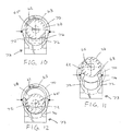
- FIGS. 1-12 show a universal strut assembly according to a first embodiment of the present disclosure.
- the universal strut assembly includes strut cylinder 28 , strut rod 24 , stop tube 50 , locking tube 62 , and pivot block 60.
- the strut assembly 10 is shown as being substantially about a central axis 65 (defined by centers of the strut cylinder 28 and strut rod 24 ) which can extend, for example, the length of the closer between the frame pivot 36 on the frame bracket 32 at a first end to an opposing bracket 18 and pin 20 at a second end.
- the stop tube 50 can be used for a multitude of different applications and mountings, and retrofitted to any strut size.
- the locking tube 62 can be anchored at one end to the strut rod 24.
- the pivot block 60 enables the locking tube 62 to pivot about a pivot pin 61 relative to the strut rod 24.
- the pivot block 60 is proximal to the mounting frame bracket 18.
- the locking tube 62 can be a steel tube attached by sliding over the strut rod 24 and subsequently fastened to the strut rod 24 at one end by the pivot block 60.
- the locking tube can be made of other materials (e.g., plastic, composite materials, other metals, etc.).
- the locking tube 62 pivots about the pivot block 60 between a first position aligned with the central axis 65 ( Figures. 4, 5 , and 10 ) and a second position not aligned with the central axis 65 ( Figures 6 , 9 , 11, and 12 ).
- the inside of the locking tube 62 can optionally include metal, plastic, and/or nylon beads to facilitate movement between the locking tube 62 , strut rod 24 , and strut cylinder 28 (not illustrated). Beads can also be used to help prevent scratching of the adjacent surfaces between the locking tube 62 , strut rod 24 , and strut cylinder 28.
- the stop tube 50 includes a collar 70 at one end 71 and a flexible clip 72 at another end 73.
- the clip end 73 is proximal to the strut cylinder 28 and distal to the pivot block 60.
- the collar end 71 surrounds the locking tube 62 at a location distal to the pivot block 60.
- the clip end 73 functions as a spring to hold the stop tube 50 in position.
- the stop tube 50 further includes a ramp or angled member 76 connecting the clip 72 and collar 70.
- the clip end 72 rides along the outer circumference 29 of the strut cylinder 28.
- the stop tube 50 'pulls' the locking tube 62 into the second position (while pivoting at the pivot block 60 ) out of alignment with the central axis of the strut cylinder 28.
- the 'pulling' of the locking tube 62 is activated automatically when the strut rod 24 reaches a predeterminable extended position.
- a terminal substantially flat section or portion of the terminal end 63 of the locking tube 62 mates with the terminal end 27 of the strut cylinder 28 while misaligning respective central axes of the locking tube 62 and strut cylinder 28 ( FIG. 6 ).
- the misalignment prevents the strut cylinder 28 from sliding rectilinearly within the locking tube 62.
- the length of the locking tube 62 and strut cylinder 28 can determine the fixed predeterminable position.
- FIGS. 1-3 show a relatively long locking tube 62 ; however, this is not required.
- the predeterminable locking position can be the full extended position of the strut rod 24 or some other position less than the full extended position.
- a single push to the clip 72 deactivates the engagement of the strut cylinder 28 and the locking tube 62.
- the strut assembly 10 aligns itself and closes completely unassisted by any further action of an operator.
- the clip end 72 can be pushed towards the strut cylinder 28.
- the pressure expands the clip end 72 partially around the strut cylinder 28 thereby aligning the strut cylinder 28 and locking tube 62 about the same co-aligned central axis.
- the stop tube 50 holds the locking tube 62 in disengaged position until the strut cylinder 28 and locking tube 62 are partially closed.
- the stop tube 50 is 'reset' when the strut assembly 10 is closed partially after disengaging the locking tube 62 and strut cylinder 28.
- the ramp 76 between the clip 72 and collar 70 , resets the stop tube 50 when assembly 10 begins to close after disengagement ( FIG. 7 ).
- the angled portion or face 63 of the terminal end of the locking tube 62 along with the ramp 76 , provides for the self-alignment between the strut cylinder 28 and the locking tube 62 about the central axis 65.
- the clip 72 functions as a spring to hold the stop tube 50 and locking tube 62 in position.
- a c-shaped clamp or open ring of the clip 72 provides a spring force that pushes the stop tube 50 into a locked position ( FIG. 11 ).
- the stop tube 50 "activates" automatically when the strut cylinder 28 reaches a predetermined extended position ( FIGS. 5 and 6 ).
- the predetermined extended position can be the fully extended position or some other position less than the fully extended position.
- a push is made to the clip 72 in a direction toward the strut cylinder 28 , whereby the clip 72 holds the locking tube 62 in a disengaged position until the strut assembly 10 is partially closed.
- the ramp 76 "resets" the stop tube 50 when the strut assembly 10 initiates closing after disengagement.
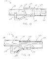
- the ramp 76 and the angled face 63 of the locking tube 62 slides along the terminal end 27 of the strut cylinder 28 until the central axes of the strut cylinder 28 and the locking tube 62 are aligned, whereby the locking tube 62 slides rectilinearly over the strut cylinder 28 ( FIGS. 7 and 8 ).
- the clip end 172 rides along the outer circumference 129 of the strut cylinder 128.
- the stop tube 150 "pulls'" the locking tube 162 into the second position (while pivoting at the pivot block) out of alignment with the central axis of the strut cylinder 128. The pulling of the locking tube 162 is activated automatically when the strut rod 124 reaches a predeterminable extended position.
- a terminal flat section or portion 152 of the terminal end of the stop tube 150 mates with the terminal end 127 of the strut cylinder 128 while misaligning respective central axes of the locking tube 162 and strut cylinder 128.
- the misalignment prevents the strut cylinder 128 from sliding rectilinearly within the locking tube 162.
- the predeterminable locking position can be the full extended position of the strut rod 124 or some other position less than the full extended position.
- a single push to the clip 172 deactivates the engagement of the strut cylinder 128 and the stop tube 150.
- the clip end 172 can be pushed towards the strut cylinder 128.
- the pressure expands the clip end 172 partially around the strut cylinder 128 thereby aligning the stop tube 150 , strut cylinder 128 , and locking tube 162 about the central axis ( FIG. 13 ).
- the stop tube 150 holds the locking tube 162 in disengaged position until the strut cylinder 128 and locking tube 162 are partially closed.
- the stop tube 150 is "reset" when the strut assembly 110 is closed partially after the disengaging the terminal ends of the stop tube 150 and strut cylinder 128.
- the ramp 176 between the clip 172 and collar 170 , resets the stop tube 150 when the strut assembly 110 is partially closed after disengagement.
- an angled portion or face 153 of the terminal end of the stop tube 150 provides for self-alignment between the strut cylinder 128 and the locking tube 162 about the central axis. It is to be appreciated that upon disengagement, the strut assembly 110 self-aligns and closes completely unassisted by any further action of an operator.
- the angled face 153 of the stop tube 150 and the ramp 176 slide along the terminal end 127 of the strut cylinder 128 until the central axes of the strut cylinder 128 , stop tube 150 , and locking tube 162 are aligned, whereby the locking tube 162 slides rectilinearly over the strut cylinder 128.
- the clip 172 functions as a spring to hold the stop tube 150 and strut cylinder 128 in position.
- the shape of the clip 172 provides a spring force that pushes the stop tube 150 into a locked position ( FIG. 14 ).
- the stop tube 150 "activates" automatically when the strut cylinder 128 reaches a predetermined extended position.
- the predetermined extended position can be the fully extended position or some other position less than the fully extended position.
- stop tube and locking tube can come in a variety of sizes.
- the stop tube can be installed after strut construction and can be retrofitted to any strut (i.e., body size, rod size, stroke, etc.).
- the angled portion of either the locking tube or stop tube and the stop tube ramp provide for a self-alignment mechanism for aligning the respective central axes of the strut cylinder, stop tube, and locking tube.
- the angled portion can be at or near the terminal ends of the stop tube or locking tube.
- the relative sizes of the stop tubes and locking tubes can be fitted for the respective applications, the desired amount of 'travel' or stroke between the strut and the strut rod, and the desired locking position.
- the hold-open apparatus including the angled portion, present on either the stop tube or locking tube.
- the angled portion 63 relative to the vertical plane is positioned from about 10 degrees to about 40 degrees 67 , while the strut assembly is in the locked position or hold-open position.
- the angled portion is positioned from about 20 degrees to about 30 degrees, with respect to the vertical plane in a predetermined direction as shown in FIG. 6 .
- the angled portion changes orientation to an 'attack angle' less than the locked position angle.
- the unlocked position angle 69 is positioned from about 15 degrees to about 35 degrees from the vertical plane, while the strut cylinder and the locking tube are approaching alignment and then become aligned ( FIG. 5 ) while the strut assembly is in the unlocked position and the central axes of the locking tube and the strut cylinder are aligned. Once the locking tube and the strut cylinder are aligned, the strut cylinder will move rectilinearly inside the locking tube ( FIG. 8 ).
- the locking tube of the hold-open apparatus moves primarily in a plane and also in a radial arc with respect to the pivot block first end of the hold-open apparatus.
- the locking tube moves in a plane defined by misaligned respective central axes of the locking tube and the strut cylinder ( FIGS. 11 and 12 ).
- the first end is located at the center of a circle and the second terminal end portion moves around a section of the radial edge of the circle (not illustrated).
- the hold-open apparatus of the present invention can advantageously be utilized as an add-on accessory for a door closer mechanism which is already in use with little retrofitting necessary and limited use of installation tools.
- the hold-open apparatus can be included on newly constructed door closer mechanisms fitted to screen and storm doors.
- the present invention provides a simple method for maintaining a door in a latched position, whether operated manually or automatically.
- the apparatus can be utilized by persons who have disabilities and cannot easily manipulate hands, fingers, digits, and/or bend over easily. Further, since the door can be activated to a hold-open position by simply opening the door, accidents that are caused by the closing door catching on the back of the legs or feet are minimized.
- stop tube and locking tube combination Another non-limiting advantage of the stop tube and locking tube combination described above is that there is no oil to introduce, monitor, leak, and/or replace. In addition, there are no seals required, and thus, no seals to wear out or replace with respect to the engagements and interactions of the stop tube and locking tube as part of the strut assembly. Additionally, it is to be appreciated that 100 percent of the unintended closure force is taken up or resisted by the point-to-point contact of the locking tube with the strut cylinder, or by the point-to-point contact of the stop tube with the strut cylinder (i.e., rigid metal components).
- the hold-open apparatus can be designed so as to be variable in length as known in the art to accommodate the user's choice of operation and angle of the door open position, etc.
- the locking tube and stop tube of the hold-open apparatus length may be varied to accommodate a particular application.
- the locking tube of the hold-open apparatus moves primarily in a plane and also in a radial arc with respect to the pivot block first end of the hold-open apparatus.
- the first end is located at the center of a circle and the second terminal end portion moves around a section of the radial edge of the circle.
- the hold-open apparatus of the present invention can advantageously be utilized as an add-on accessory for a door closer mechanism which is already in use with little retrofitting necessary and limited use of installation tools.
- the hold-open apparatus can be included on newly constructed door closer mechanisms fitted to screen and storm doors.
- the present invention provides a simple method for maintaining a door in a latched position, whether operated manually or automatically.
- the apparatus can be utilized by persons who have disabilities and cannot easily manipulate hands, fingers, digits, and/or bend over easily. Further, since the door can be activated to a hold-open position by simply opening the door, accidents that are caused by the closing door catching on the back of the legs or feet are minimized.
- the advantage in all cases to the user and as compared to other similar devices is that the apparatus can be operated completely automatically by simply opening the door without any additional manual operation. This feature is particularly advantageous when the user has both hands full when entering, or when assisting others since the door can be automatically locked open and disengaged by simply moving the stop tube.
- REFERENCE NUMBERS 10 strut assembly 12 cylinder 70 collar 14 head end 71 one or second end 16 door 72 clip 18 bracket 73 clip end or first end 20 pin 76 ramp or angled member 24 strut rod 110 strut assembly 27 terminal end 124 strut rod 28 strut cylinder 127 terminal end 29 outer circumference 128 strut cylinder or cylinder 30 frame 129 outer circumference 32 frame bracket 150 stop tube 34 bracket aperture 152 terminal flat section or portion 36 pin 40 mounting apertures 153 angled face 50 stop tube 162 locking tube 60 pivot block 170 collar 61 pivot pin 172 clip 62 locking tube 176 ramp 63 terminal end or face 65 central axis
Landscapes
- Engineering & Computer Science (AREA)
- General Engineering & Computer Science (AREA)
- Mechanical Engineering (AREA)
- Closing And Opening Devices For Wings, And Checks For Wings (AREA)
- Fluid-Damping Devices (AREA)
- Power-Operated Mechanisms For Wings (AREA)
Claims (13)
- Strebenbaugruppe (10), die einen Halte- und Freigabemechanismus enthält, der so konfiguriert ist, dass er an einem Schließer vom Zylindertyp angebracht werden kann, wobei die Strebenbaugruppe (10) einen Strebenzylinder (28) und eine Strebenstange (24) umfasst, wobei der Mechanismus einen Schwenkblock (60), ein Verriegelungsrohr (62) und ein Anschlagrohr (50) umfasst, wobei das Anschlagrohr an einem ersten Ende (73) eine Klammer (72) aufweist und an einem zweiten Ende (71) einen Bund (70) aufweist, wobei die Klammer (72) so konfiguriert ist, dass sie sich von einer ersten Position in eine zweite Position bewegt, während das Verriegelungsrohr (62) an einem ersten Ende geschwenkt wird, um das Verriegelungsrohr an einem anderen Ende mit dem Strebenzylinder (28) in Eingriff zu bringen, wodurch die Strebenbaugruppe in einer ausgezogenen Position gehalten wird,
dadurch gekennzeichnet, dass
das Anschlagrohr (50) eine starre, gewinkelte Rampe aufweist, die die Klammer (72) und den Bund (70) verbindet. - Baugruppe (10) nach Anspruch 1, wobei das Verriegelungsrohr (62) an dem ersten Ende schwenkbar mit der Strebenstange proximal zu einer Montagerahmenhalterung (18) in Eingriff steht.
- Baugruppe (10) nach Anspruch 1 oder 2, wobei das Verriegelungsrohr (62) ein gewinkeltes zweites Ende distal zu der Montagerahmenhalterung (18) aufweist.
- Baugruppe (10) nach Anspruch 2 oder 3, wobei sich das Verriegelungsrohr (62) in einem radialen Bogen relativ zu dem ersten Ende bewegt.
- Baugruppe (10) nach einem der Ansprüche 1 bis 4, wobei das Anschlagrohr ein gewinkeltes zweites Ende distal zu der Montagerahmenhalterung (18) aufweist, wobei das gewinkelte zweite Ende des Weiteren einen flachen Abschnitt orthogonal zu einer Mittelachse des Verriegelungsrohres (62) aufweist.
- Baugruppe (10) nach einem der Ansprüche 1 bis 5, wobei die Klammer einen verformbaren offenen Ring aufweist, der von der ersten Position in die zweite Position bewegt werden kann.
- Baugruppe (10) nach einem der Ansprüche 1 bis 6, die ein gewinkeltes zweites Ende distal zu der Montagerahmenhalterung (18) aufweist, wobei das gewinkelte zweite Ende des Weiteren einen flachen Abschnitt orthogonal zu einer Mittelachse des Verriegelungsrohres aufweist, wobei die zweite Position das Endstück des flachen Abschnitts des gewinkelten zweiten Endes gegen ein Endstück des Strebenzylinders hält.
- Baugruppe (10) nach einem der Ansprüche 1 bis 7, wobei sich das Verriegelungsrohr in einem radialen Bogen relativ zu dem ersten Ende und in einer Ebene bewegt, die durch fehlausgerichtete jeweilige Mittelachsen des Verriegelungsrohres und des Strebenzylinders definiert wird.
- Strebenhalte- und -freigabemechanismus, der so konfiguriert ist, dass er an einem Schließer vom Zylindertyp angebracht werden kann, wobei der Mechanismus ein Anschlagrohr, ein Verriegelungsrohr und einen Schwenkblock umfasst, wobei das Anschlagrohr eine Klammer (72) an einem ersten Ende (73) und einen Bund (70) an einem zweiten Ende (71) aufweist, wobei das Verriegelungsrohr so konfiguriert ist, dass es an einem ersten Ende an dem Schließer vom Zylindertyp angebracht werden kann, wobei der Klammer (72) aus einer ersten Position in eine zweite Position bewegt werden kann, während das Verriegelungsrohr an dem ersten Ende geschwenkt wird, um das Verriegelungsrohr an einem zweiten Ende mit dem Schließer vom Zylindertyp in Eingriff zu bringen, wodurch der Schließer vom Zylindertyp in einer ausgezogenen Position gehalten wird, wobei das Anschlagrohr, das Verriegelungsrohr oder eine Kombination davon ein gewinkeltes zweites Ende distal zu dem ersten Ende aufweist,
dadurch gekennzeichnet, dass
das Anschlagrohr (50) eine starre, gewinkelte Rampe aufweist, die die Klammer (72) und den Bund (70) verbindet. - Mechanismus nach Anspruch 9, wobei das Verriegelungsrohr von einer auf eine Mittelachse des Schließers vom Zylindertyp ausgerichteten Ausrichtung in der ersten Position in eine nicht auf die Mittelachse des Schließers vom Zylindertyp ausgerichtete Ausrichtung in der zweiten Position schwenkt.
- Mechanismus nach Anspruch 9 oder 10, wobei die Klammer eine verformbare offene C-Klammer aufweist, die von der ersten Position in die zweite Position bewegt werden kann.
- Mechanismus nach Anspruch 10 oder 11, wobei das gewinkelte zweite Ende und die gewinkelte Rampe automatisch eine Mittelachse des Verriegelungsrohres auf die Mittelachse des Schließers vom Zylindertyp ausrichten, wenn sich die Klammer von der zweiten Position in die erste Position bewegt.
- Mechanismus nach einem der Ansprüche 9-12, wobei sich das Verriegelungsrohr in einem radialen Bogen relativ zu dem ersten Ende und in einer Ebene bewegt, die durch fehlausgerichtete jeweilige Mittelachsen des Verriegelungsrohres und des Strebenzylinders definiert wird.
Applications Claiming Priority (1)
| Application Number | Priority Date | Filing Date | Title |
|---|---|---|---|
| US201361762383P | 2013-02-08 | 2013-02-08 |
Publications (3)
| Publication Number | Publication Date |
|---|---|
| EP2765327A2 EP2765327A2 (de) | 2014-08-13 |
| EP2765327A3 EP2765327A3 (de) | 2018-03-07 |
| EP2765327B1 true EP2765327B1 (de) | 2020-12-02 |
Family
ID=51274251
Family Applications (1)
| Application Number | Title | Priority Date | Filing Date |
|---|---|---|---|
| EP14000456.5A Active EP2765327B1 (de) | 2013-02-08 | 2014-02-08 | Universelles Anschlagrohr |
Country Status (6)
| Country | Link |
|---|---|
| US (1) | US9032587B2 (de) |
| EP (1) | EP2765327B1 (de) |
| CN (1) | CN103982105B (de) |
| AU (1) | AU2014200626A1 (de) |
| CA (1) | CA2842052A1 (de) |
| NZ (1) | NZ620844A (de) |
Families Citing this family (18)
| Publication number | Priority date | Publication date | Assignee | Title |
|---|---|---|---|---|
| FR2972476B1 (fr) * | 2011-03-09 | 2014-01-24 | Norinco | Dispositif d'assistance a l'ouverture d'un element de recouvrement monte pivotant relativement a un bord d'un cadre |
| US20140332652A1 (en) * | 2013-05-12 | 2014-11-13 | John E. Hansen | Gas strut support |
| US9746014B1 (en) * | 2014-01-15 | 2017-08-29 | Nicholas C. Cassaro | Strut retention device |
| WO2015146754A1 (ja) * | 2014-03-26 | 2015-10-01 | アイシン精機 株式会社 | ドア開度調整装置 |
| CN104295176A (zh) * | 2014-10-30 | 2015-01-21 | 安徽捷迅光电技术有限公司 | 一种箱子气弹簧支撑臂 |
| USD750952S1 (en) * | 2015-01-19 | 2016-03-08 | Solomon Herzog | Patio door closer |
| US9828795B1 (en) * | 2015-04-28 | 2017-11-28 | Wayne W. Ramsdell | Hinge and applications thereof |
| US11530560B1 (en) | 2015-04-28 | 2022-12-20 | Wayne W. Ramsdell | Hinge and applications thereof |
| US10428565B1 (en) | 2015-04-28 | 2019-10-01 | Wayne W. Ramsdell | Hinge and applications thereof |
| CN105587199B (zh) * | 2016-02-25 | 2017-06-06 | 希美克(广州)实业有限公司 | 一种气压闭门器 |
| EP3545152B1 (de) * | 2016-11-25 | 2021-12-15 | Jämtinvent AB | Sicherheitsstrebenvorrichtung |
| IT201800003993A1 (it) * | 2018-03-27 | 2019-09-27 | Elica Spa | Involucro di una cappa per l’aspirazione di fumi di cottura |
| US20220042359A1 (en) * | 2020-08-04 | 2022-02-10 | Timothy B. Bothwell | Lift support bracing device and method |
| CN111962990A (zh) * | 2020-08-21 | 2020-11-20 | 广东电网有限责任公司 | 推拉门窗防风杆 |
| EP4006277B1 (de) * | 2020-11-25 | 2023-05-10 | Giesse S.P.A. | Vorrichtung zur begrenzung der öffnung von türen oder fenstern |
| EP4116149A1 (de) * | 2021-07-06 | 2023-01-11 | Thule Sweden AB | Kippmechanismus |
| CN113958219B (zh) * | 2021-10-19 | 2022-12-02 | 美创节能科技(湖州)有限公司 | 可紧急开启的复合式自锁天窗 |
| FR3151611B1 (fr) * | 2023-07-28 | 2025-09-26 | Ej Emea | Dispositif d’aide à l’ouverture sécurisée d’un couvercle de regard pivotant |
Citations (2)
| Publication number | Priority date | Publication date | Assignee | Title |
|---|---|---|---|---|
| US4813100A (en) * | 1988-02-04 | 1989-03-21 | King Daniel P | Closure check |
| EP1211372A1 (de) * | 2000-12-01 | 2002-06-05 | Thales | Vorrichtung zum Sperren eines Zylinderantriebs einer Tür in offener Stellung |
Family Cites Families (10)
| Publication number | Priority date | Publication date | Assignee | Title |
|---|---|---|---|---|
| US3708825A (en) * | 1971-11-24 | 1973-01-09 | R Wood | Door check and door stop combination |
| GB1460948A (en) * | 1974-04-30 | 1977-01-06 | Davitance Ltd | Spring clips |
| US4639969A (en) | 1985-01-09 | 1987-02-03 | Obenshain D Noel | Door closer mechanism |
| US4815163A (en) | 1988-06-30 | 1989-03-28 | Simmons William O | Storm door lock apparatus |
| US5575513A (en) | 1995-04-03 | 1996-11-19 | Tuttle; Willis A. | Automobile hood strut lock |
| US5592780A (en) | 1995-06-07 | 1997-01-14 | Checkovich; Peter | Door position controlling apparatus |
| US5659925A (en) | 1996-02-21 | 1997-08-26 | Patterson; E. Ennalls | Door closer holding mechanism |
| CN1223750C (zh) * | 2001-01-15 | 2005-10-19 | Vkr控股公司 | 具有锁定装置的伸缩弹簧部件 |
| JP4564905B2 (ja) * | 2005-08-30 | 2010-10-20 | カヤバ工業株式会社 | ステーダンパ |
| US7730579B2 (en) * | 2006-09-19 | 2010-06-08 | Thomas Edward Coe | Door closure apparatus |
-
2014
- 2014-02-03 US US14/170,868 patent/US9032587B2/en active Active
- 2014-02-04 CA CA2842052A patent/CA2842052A1/en not_active Abandoned
- 2014-02-05 NZ NZ620844A patent/NZ620844A/en not_active IP Right Cessation
- 2014-02-05 AU AU2014200626A patent/AU2014200626A1/en not_active Abandoned
- 2014-02-08 EP EP14000456.5A patent/EP2765327B1/de active Active
- 2014-02-08 CN CN201410139118.2A patent/CN103982105B/zh active Active
Patent Citations (2)
| Publication number | Priority date | Publication date | Assignee | Title |
|---|---|---|---|---|
| US4813100A (en) * | 1988-02-04 | 1989-03-21 | King Daniel P | Closure check |
| EP1211372A1 (de) * | 2000-12-01 | 2002-06-05 | Thales | Vorrichtung zum Sperren eines Zylinderantriebs einer Tür in offener Stellung |
Also Published As
| Publication number | Publication date |
|---|---|
| US20140223692A1 (en) | 2014-08-14 |
| US9032587B2 (en) | 2015-05-19 |
| EP2765327A2 (de) | 2014-08-13 |
| CN103982105A (zh) | 2014-08-13 |
| AU2014200626A1 (en) | 2014-08-28 |
| EP2765327A3 (de) | 2018-03-07 |
| CN103982105B (zh) | 2017-07-28 |
| CA2842052A1 (en) | 2014-08-08 |
| NZ620844A (en) | 2014-03-28 |
Similar Documents
| Publication | Publication Date | Title |
|---|---|---|
| EP2765327B1 (de) | Universelles Anschlagrohr | |
| US6904643B2 (en) | Door closer hold-open apparatus | |
| US8763851B2 (en) | Door assembly for ice storage bin | |
| US8505240B2 (en) | Casement and awning window opening limit device | |
| US6317922B1 (en) | Door closer | |
| US8707521B1 (en) | Adjustable door jamb lock | |
| US10641026B2 (en) | Automatic door stopping-closing device and door | |
| EP3239439B1 (de) | Zu öffnendes dachfenster mit aktivem schloss | |
| CA2857810A1 (en) | Window lock with corner drive and lock points along a side and the top of the window | |
| US6615449B1 (en) | Releasable locking assembly for a door control cylinder | |
| US5951071A (en) | Door brace | |
| US7730579B2 (en) | Door closure apparatus | |
| US20090309375A1 (en) | Automatic Gate Lock | |
| KR200479683Y1 (ko) | 초기 개폐 기능을 갖는 미닫이문용 잠금장치 | |
| EP2728216B1 (de) | Teleskopische Federeinheit mit einer Steuerungsvorrichtung | |
| US20170328098A1 (en) | Door stopper | |
| US4678213A (en) | Locking apparatus | |
| CA2390982A1 (en) | Closure device | |
| CA2757154C (en) | Casement and awning window opening limit device | |
| KR101202521B1 (ko) | 창문용 초기 개방장치 | |
| CN209586179U (zh) | 安防门及安全系统 | |
| CA2999453C (en) | Automatic door stopping-closing device and door | |
| DE102005020780A1 (de) | Türschliesser | |
| AU2005244516A1 (en) | A mortice lock | |
| CA2845526A1 (en) | Adjustable door jamb lock |
Legal Events
| Date | Code | Title | Description |
|---|---|---|---|
| PUAI | Public reference made under article 153(3) epc to a published international application that has entered the european phase |
Free format text: ORIGINAL CODE: 0009012 |
|
| 17P | Request for examination filed |
Effective date: 20140208 |
|
| AK | Designated contracting states |
Kind code of ref document: A2 Designated state(s): AL AT BE BG CH CY CZ DE DK EE ES FI FR GB GR HR HU IE IS IT LI LT LU LV MC MK MT NL NO PL PT RO RS SE SI SK SM TR |
|
| AX | Request for extension of the european patent |
Extension state: BA ME |
|
| RIN1 | Information on inventor provided before grant (corrected) |
Inventor name: THOMAS, MARK Inventor name: VINE, ADRAIN Inventor name: ADOLINE, JACK |
|
| PUAL | Search report despatched |
Free format text: ORIGINAL CODE: 0009013 |
|
| AK | Designated contracting states |
Kind code of ref document: A3 Designated state(s): AL AT BE BG CH CY CZ DE DK EE ES FI FR GB GR HR HU IE IS IT LI LT LU LV MC MK MT NL NO PL PT RO RS SE SI SK SM TR |
|
| AX | Request for extension of the european patent |
Extension state: BA ME |
|
| RIC1 | Information provided on ipc code assigned before grant |
Ipc: E05F 1/10 20060101ALI20180129BHEP Ipc: E05F 3/22 20060101ALI20180129BHEP Ipc: F16F 9/56 20060101AFI20180129BHEP Ipc: E05C 17/30 20060101ALI20180129BHEP |
|
| STAA | Information on the status of an ep patent application or granted ep patent |
Free format text: STATUS: REQUEST FOR EXAMINATION WAS MADE |
|
| R17P | Request for examination filed (corrected) |
Effective date: 20180910 |
|
| RBV | Designated contracting states (corrected) |
Designated state(s): AL AT BE BG CH CY CZ DE DK EE ES FI FR GB GR HR HU IE IS IT LI LT LU LV MC MK MT NL NO PL PT RO RS SE SI SK SM TR |
|
| STAA | Information on the status of an ep patent application or granted ep patent |
Free format text: STATUS: EXAMINATION IS IN PROGRESS |
|
| 17Q | First examination report despatched |
Effective date: 20181022 |
|
| GRAP | Despatch of communication of intention to grant a patent |
Free format text: ORIGINAL CODE: EPIDOSNIGR1 |
|
| STAA | Information on the status of an ep patent application or granted ep patent |
Free format text: STATUS: GRANT OF PATENT IS INTENDED |
|
| INTG | Intention to grant announced |
Effective date: 20200619 |
|
| GRAS | Grant fee paid |
Free format text: ORIGINAL CODE: EPIDOSNIGR3 |
|
| GRAA | (expected) grant |
Free format text: ORIGINAL CODE: 0009210 |
|
| STAA | Information on the status of an ep patent application or granted ep patent |
Free format text: STATUS: THE PATENT HAS BEEN GRANTED |
|
| AK | Designated contracting states |
Kind code of ref document: B1 Designated state(s): AL AT BE BG CH CY CZ DE DK EE ES FI FR GB GR HR HU IE IS IT LI LT LU LV MC MK MT NL NO PL PT RO RS SE SI SK SM TR |
|
| REG | Reference to a national code |
Ref country code: GB Ref legal event code: FG4D |
|
| RIN1 | Information on inventor provided before grant (corrected) |
Inventor name: VINE, ADRAIN Inventor name: THOMAS, MARK Inventor name: ADOLINE, JACK |
|
| REG | Reference to a national code |
Ref country code: AT Ref legal event code: REF Ref document number: 1341262 Country of ref document: AT Kind code of ref document: T Effective date: 20201215 Ref country code: CH Ref legal event code: EP |
|
| REG | Reference to a national code |
Ref country code: DE Ref legal event code: R096 Ref document number: 602014072840 Country of ref document: DE |
|
| REG | Reference to a national code |
Ref country code: IE Ref legal event code: FG4D |
|
| PG25 | Lapsed in a contracting state [announced via postgrant information from national office to epo] |
Ref country code: RS Free format text: LAPSE BECAUSE OF FAILURE TO SUBMIT A TRANSLATION OF THE DESCRIPTION OR TO PAY THE FEE WITHIN THE PRESCRIBED TIME-LIMIT Effective date: 20201202 Ref country code: FI Free format text: LAPSE BECAUSE OF FAILURE TO SUBMIT A TRANSLATION OF THE DESCRIPTION OR TO PAY THE FEE WITHIN THE PRESCRIBED TIME-LIMIT Effective date: 20201202 Ref country code: NO Free format text: LAPSE BECAUSE OF FAILURE TO SUBMIT A TRANSLATION OF THE DESCRIPTION OR TO PAY THE FEE WITHIN THE PRESCRIBED TIME-LIMIT Effective date: 20210302 Ref country code: GR Free format text: LAPSE BECAUSE OF FAILURE TO SUBMIT A TRANSLATION OF THE DESCRIPTION OR TO PAY THE FEE WITHIN THE PRESCRIBED TIME-LIMIT Effective date: 20210303 |
|
| REG | Reference to a national code |
Ref country code: NL Ref legal event code: MP Effective date: 20201202 |
|
| REG | Reference to a national code |
Ref country code: AT Ref legal event code: MK05 Ref document number: 1341262 Country of ref document: AT Kind code of ref document: T Effective date: 20201202 |
|
| PG25 | Lapsed in a contracting state [announced via postgrant information from national office to epo] |
Ref country code: BG Free format text: LAPSE BECAUSE OF FAILURE TO SUBMIT A TRANSLATION OF THE DESCRIPTION OR TO PAY THE FEE WITHIN THE PRESCRIBED TIME-LIMIT Effective date: 20210302 Ref country code: LV Free format text: LAPSE BECAUSE OF FAILURE TO SUBMIT A TRANSLATION OF THE DESCRIPTION OR TO PAY THE FEE WITHIN THE PRESCRIBED TIME-LIMIT Effective date: 20201202 Ref country code: PL Free format text: LAPSE BECAUSE OF FAILURE TO SUBMIT A TRANSLATION OF THE DESCRIPTION OR TO PAY THE FEE WITHIN THE PRESCRIBED TIME-LIMIT Effective date: 20201202 Ref country code: SE Free format text: LAPSE BECAUSE OF FAILURE TO SUBMIT A TRANSLATION OF THE DESCRIPTION OR TO PAY THE FEE WITHIN THE PRESCRIBED TIME-LIMIT Effective date: 20201202 |
|
| PG25 | Lapsed in a contracting state [announced via postgrant information from national office to epo] |
Ref country code: NL Free format text: LAPSE BECAUSE OF FAILURE TO SUBMIT A TRANSLATION OF THE DESCRIPTION OR TO PAY THE FEE WITHIN THE PRESCRIBED TIME-LIMIT Effective date: 20201202 Ref country code: HR Free format text: LAPSE BECAUSE OF FAILURE TO SUBMIT A TRANSLATION OF THE DESCRIPTION OR TO PAY THE FEE WITHIN THE PRESCRIBED TIME-LIMIT Effective date: 20201202 |
|
| REG | Reference to a national code |
Ref country code: LT Ref legal event code: MG9D |
|
| PG25 | Lapsed in a contracting state [announced via postgrant information from national office to epo] |
Ref country code: SM Free format text: LAPSE BECAUSE OF FAILURE TO SUBMIT A TRANSLATION OF THE DESCRIPTION OR TO PAY THE FEE WITHIN THE PRESCRIBED TIME-LIMIT Effective date: 20201202 Ref country code: EE Free format text: LAPSE BECAUSE OF FAILURE TO SUBMIT A TRANSLATION OF THE DESCRIPTION OR TO PAY THE FEE WITHIN THE PRESCRIBED TIME-LIMIT Effective date: 20201202 Ref country code: CZ Free format text: LAPSE BECAUSE OF FAILURE TO SUBMIT A TRANSLATION OF THE DESCRIPTION OR TO PAY THE FEE WITHIN THE PRESCRIBED TIME-LIMIT Effective date: 20201202 Ref country code: PT Free format text: LAPSE BECAUSE OF FAILURE TO SUBMIT A TRANSLATION OF THE DESCRIPTION OR TO PAY THE FEE WITHIN THE PRESCRIBED TIME-LIMIT Effective date: 20210405 Ref country code: RO Free format text: LAPSE BECAUSE OF FAILURE TO SUBMIT A TRANSLATION OF THE DESCRIPTION OR TO PAY THE FEE WITHIN THE PRESCRIBED TIME-LIMIT Effective date: 20201202 Ref country code: SK Free format text: LAPSE BECAUSE OF FAILURE TO SUBMIT A TRANSLATION OF THE DESCRIPTION OR TO PAY THE FEE WITHIN THE PRESCRIBED TIME-LIMIT Effective date: 20201202 Ref country code: LT Free format text: LAPSE BECAUSE OF FAILURE TO SUBMIT A TRANSLATION OF THE DESCRIPTION OR TO PAY THE FEE WITHIN THE PRESCRIBED TIME-LIMIT Effective date: 20201202 |
|
| PG25 | Lapsed in a contracting state [announced via postgrant information from national office to epo] |
Ref country code: AT Free format text: LAPSE BECAUSE OF FAILURE TO SUBMIT A TRANSLATION OF THE DESCRIPTION OR TO PAY THE FEE WITHIN THE PRESCRIBED TIME-LIMIT Effective date: 20201202 |
|
| REG | Reference to a national code |
Ref country code: DE Ref legal event code: R097 Ref document number: 602014072840 Country of ref document: DE |
|
| PG25 | Lapsed in a contracting state [announced via postgrant information from national office to epo] |
Ref country code: IS Free format text: LAPSE BECAUSE OF FAILURE TO SUBMIT A TRANSLATION OF THE DESCRIPTION OR TO PAY THE FEE WITHIN THE PRESCRIBED TIME-LIMIT Effective date: 20210402 Ref country code: MC Free format text: LAPSE BECAUSE OF FAILURE TO SUBMIT A TRANSLATION OF THE DESCRIPTION OR TO PAY THE FEE WITHIN THE PRESCRIBED TIME-LIMIT Effective date: 20201202 |
|
| PLBE | No opposition filed within time limit |
Free format text: ORIGINAL CODE: 0009261 |
|
| STAA | Information on the status of an ep patent application or granted ep patent |
Free format text: STATUS: NO OPPOSITION FILED WITHIN TIME LIMIT |
|
| REG | Reference to a national code |
Ref country code: BE Ref legal event code: MM Effective date: 20210228 |
|
| PG25 | Lapsed in a contracting state [announced via postgrant information from national office to epo] |
Ref country code: IT Free format text: LAPSE BECAUSE OF FAILURE TO SUBMIT A TRANSLATION OF THE DESCRIPTION OR TO PAY THE FEE WITHIN THE PRESCRIBED TIME-LIMIT Effective date: 20201202 Ref country code: CH Free format text: LAPSE BECAUSE OF NON-PAYMENT OF DUE FEES Effective date: 20210228 Ref country code: AL Free format text: LAPSE BECAUSE OF FAILURE TO SUBMIT A TRANSLATION OF THE DESCRIPTION OR TO PAY THE FEE WITHIN THE PRESCRIBED TIME-LIMIT Effective date: 20201202 Ref country code: LI Free format text: LAPSE BECAUSE OF NON-PAYMENT OF DUE FEES Effective date: 20210228 Ref country code: LU Free format text: LAPSE BECAUSE OF NON-PAYMENT OF DUE FEES Effective date: 20210208 |
|
| 26N | No opposition filed |
Effective date: 20210903 |
|
| GBPC | Gb: european patent ceased through non-payment of renewal fee |
Effective date: 20210302 |
|
| PG25 | Lapsed in a contracting state [announced via postgrant information from national office to epo] |
Ref country code: DK Free format text: LAPSE BECAUSE OF FAILURE TO SUBMIT A TRANSLATION OF THE DESCRIPTION OR TO PAY THE FEE WITHIN THE PRESCRIBED TIME-LIMIT Effective date: 20201202 Ref country code: ES Free format text: LAPSE BECAUSE OF FAILURE TO SUBMIT A TRANSLATION OF THE DESCRIPTION OR TO PAY THE FEE WITHIN THE PRESCRIBED TIME-LIMIT Effective date: 20201202 Ref country code: SI Free format text: LAPSE BECAUSE OF FAILURE TO SUBMIT A TRANSLATION OF THE DESCRIPTION OR TO PAY THE FEE WITHIN THE PRESCRIBED TIME-LIMIT Effective date: 20201202 |
|
| PG25 | Lapsed in a contracting state [announced via postgrant information from national office to epo] |
Ref country code: IE Free format text: LAPSE BECAUSE OF NON-PAYMENT OF DUE FEES Effective date: 20210208 Ref country code: GB Free format text: LAPSE BECAUSE OF NON-PAYMENT OF DUE FEES Effective date: 20210302 |
|
| PG25 | Lapsed in a contracting state [announced via postgrant information from national office to epo] |
Ref country code: IS Free format text: LAPSE BECAUSE OF FAILURE TO SUBMIT A TRANSLATION OF THE DESCRIPTION OR TO PAY THE FEE WITHIN THE PRESCRIBED TIME-LIMIT Effective date: 20210402 |
|
| PG25 | Lapsed in a contracting state [announced via postgrant information from national office to epo] |
Ref country code: BE Free format text: LAPSE BECAUSE OF NON-PAYMENT OF DUE FEES Effective date: 20210228 |
|
| PG25 | Lapsed in a contracting state [announced via postgrant information from national office to epo] |
Ref country code: HU Free format text: LAPSE BECAUSE OF FAILURE TO SUBMIT A TRANSLATION OF THE DESCRIPTION OR TO PAY THE FEE WITHIN THE PRESCRIBED TIME-LIMIT; INVALID AB INITIO Effective date: 20140208 |
|
| PG25 | Lapsed in a contracting state [announced via postgrant information from national office to epo] |
Ref country code: CY Free format text: LAPSE BECAUSE OF FAILURE TO SUBMIT A TRANSLATION OF THE DESCRIPTION OR TO PAY THE FEE WITHIN THE PRESCRIBED TIME-LIMIT Effective date: 20201202 |
|
| P01 | Opt-out of the competence of the unified patent court (upc) registered |
Effective date: 20230615 |
|
| PG25 | Lapsed in a contracting state [announced via postgrant information from national office to epo] |
Ref country code: MK Free format text: LAPSE BECAUSE OF FAILURE TO SUBMIT A TRANSLATION OF THE DESCRIPTION OR TO PAY THE FEE WITHIN THE PRESCRIBED TIME-LIMIT Effective date: 20201202 |
|
| PG25 | Lapsed in a contracting state [announced via postgrant information from national office to epo] |
Ref country code: MT Free format text: LAPSE BECAUSE OF FAILURE TO SUBMIT A TRANSLATION OF THE DESCRIPTION OR TO PAY THE FEE WITHIN THE PRESCRIBED TIME-LIMIT Effective date: 20201202 |
|
| PGFP | Annual fee paid to national office [announced via postgrant information from national office to epo] |
Ref country code: DE Payment date: 20250114 Year of fee payment: 12 |
|
| PGFP | Annual fee paid to national office [announced via postgrant information from national office to epo] |
Ref country code: FR Payment date: 20250121 Year of fee payment: 12 |
|
| PG25 | Lapsed in a contracting state [announced via postgrant information from national office to epo] |
Ref country code: TR Free format text: LAPSE BECAUSE OF FAILURE TO SUBMIT A TRANSLATION OF THE DESCRIPTION OR TO PAY THE FEE WITHIN THE PRESCRIBED TIME-LIMIT Effective date: 20201202 |