EP2764812B1 - Robot de nettoyage - Google Patents
Robot de nettoyage Download PDFInfo
- Publication number
- EP2764812B1 EP2764812B1 EP13154994.1A EP13154994A EP2764812B1 EP 2764812 B1 EP2764812 B1 EP 2764812B1 EP 13154994 A EP13154994 A EP 13154994A EP 2764812 B1 EP2764812 B1 EP 2764812B1
- Authority
- EP
- European Patent Office
- Prior art keywords
- cleaning robot
- measuring device
- floor
- cleaned
- distance
- Prior art date
- Legal status (The legal status is an assumption and is not a legal conclusion. Google has not performed a legal analysis and makes no representation as to the accuracy of the status listed.)
- Active
Links
- 238000004140 cleaning Methods 0.000 title claims description 237
- 239000007787 solid Substances 0.000 claims description 57
- 238000005259 measurement Methods 0.000 claims description 51
- 238000011156 evaluation Methods 0.000 claims description 5
- 230000002596 correlated effect Effects 0.000 claims description 4
- 239000011159 matrix material Substances 0.000 claims description 3
- 238000013459 approach Methods 0.000 claims description 2
- 230000001419 dependent effect Effects 0.000 claims description 2
- 238000001514 detection method Methods 0.000 description 6
- 230000033001 locomotion Effects 0.000 description 6
- 230000008859 change Effects 0.000 description 5
- XLYOFNOQVPJJNP-UHFFFAOYSA-N water Substances O XLYOFNOQVPJJNP-UHFFFAOYSA-N 0.000 description 5
- 238000005286 illumination Methods 0.000 description 4
- 230000004807 localization Effects 0.000 description 4
- 239000007788 liquid Substances 0.000 description 3
- 238000000034 method Methods 0.000 description 2
- 230000003287 optical effect Effects 0.000 description 2
- 230000003595 spectral effect Effects 0.000 description 2
- 238000002604 ultrasonography Methods 0.000 description 2
- 230000004913 activation Effects 0.000 description 1
- 230000000875 corresponding effect Effects 0.000 description 1
- 230000008878 coupling Effects 0.000 description 1
- 238000010168 coupling process Methods 0.000 description 1
- 238000005859 coupling reaction Methods 0.000 description 1
- 230000009849 deactivation Effects 0.000 description 1
- 238000005108 dry cleaning Methods 0.000 description 1
- 230000000694 effects Effects 0.000 description 1
- 239000013505 freshwater Substances 0.000 description 1
- 230000007246 mechanism Effects 0.000 description 1
- 239000000203 mixture Substances 0.000 description 1
- 238000012544 monitoring process Methods 0.000 description 1
- 230000008569 process Effects 0.000 description 1
- 230000005855 radiation Effects 0.000 description 1
- 230000035939 shock Effects 0.000 description 1
- 238000010408 sweeping Methods 0.000 description 1
Images

Classifications
-
- A—HUMAN NECESSITIES
- A47—FURNITURE; DOMESTIC ARTICLES OR APPLIANCES; COFFEE MILLS; SPICE MILLS; SUCTION CLEANERS IN GENERAL
- A47L—DOMESTIC WASHING OR CLEANING; SUCTION CLEANERS IN GENERAL
- A47L11/00—Machines for cleaning floors, carpets, furniture, walls, or wall coverings
- A47L11/40—Parts or details of machines not provided for in groups A47L11/02 - A47L11/38, or not restricted to one of these groups, e.g. handles, arrangements of switches, skirts, buffers, levers
- A47L11/4011—Regulation of the cleaning machine by electric means; Control systems and remote control systems therefor
-
- A—HUMAN NECESSITIES
- A47—FURNITURE; DOMESTIC ARTICLES OR APPLIANCES; COFFEE MILLS; SPICE MILLS; SUCTION CLEANERS IN GENERAL
- A47L—DOMESTIC WASHING OR CLEANING; SUCTION CLEANERS IN GENERAL
- A47L11/00—Machines for cleaning floors, carpets, furniture, walls, or wall coverings
- A47L11/29—Floor-scrubbing machines characterised by means for taking-up dirty liquid
- A47L11/292—Floor-scrubbing machines characterised by means for taking-up dirty liquid having rotary tools
- A47L11/293—Floor-scrubbing machines characterised by means for taking-up dirty liquid having rotary tools the tools being disc brushes
-
- A—HUMAN NECESSITIES
- A47—FURNITURE; DOMESTIC ARTICLES OR APPLIANCES; COFFEE MILLS; SPICE MILLS; SUCTION CLEANERS IN GENERAL
- A47L—DOMESTIC WASHING OR CLEANING; SUCTION CLEANERS IN GENERAL
- A47L11/00—Machines for cleaning floors, carpets, furniture, walls, or wall coverings
- A47L11/29—Floor-scrubbing machines characterised by means for taking-up dirty liquid
- A47L11/30—Floor-scrubbing machines characterised by means for taking-up dirty liquid by suction
- A47L11/302—Floor-scrubbing machines characterised by means for taking-up dirty liquid by suction having rotary tools
- A47L11/305—Floor-scrubbing machines characterised by means for taking-up dirty liquid by suction having rotary tools the tools being disc brushes
-
- A—HUMAN NECESSITIES
- A47—FURNITURE; DOMESTIC ARTICLES OR APPLIANCES; COFFEE MILLS; SPICE MILLS; SUCTION CLEANERS IN GENERAL
- A47L—DOMESTIC WASHING OR CLEANING; SUCTION CLEANERS IN GENERAL
- A47L11/00—Machines for cleaning floors, carpets, furniture, walls, or wall coverings
- A47L11/40—Parts or details of machines not provided for in groups A47L11/02 - A47L11/38, or not restricted to one of these groups, e.g. handles, arrangements of switches, skirts, buffers, levers
- A47L11/4061—Steering means; Means for avoiding obstacles; Details related to the place where the driver is accommodated
-
- G—PHYSICS
- G05—CONTROLLING; REGULATING
- G05D—SYSTEMS FOR CONTROLLING OR REGULATING NON-ELECTRIC VARIABLES
- G05D1/00—Control of position, course, altitude or attitude of land, water, air or space vehicles, e.g. using automatic pilots
- G05D1/02—Control of position or course in two dimensions
- G05D1/021—Control of position or course in two dimensions specially adapted to land vehicles
- G05D1/0231—Control of position or course in two dimensions specially adapted to land vehicles using optical position detecting means
- G05D1/0242—Control of position or course in two dimensions specially adapted to land vehicles using optical position detecting means using non-visible light signals, e.g. IR or UV signals
-
- G—PHYSICS
- G05—CONTROLLING; REGULATING
- G05D—SYSTEMS FOR CONTROLLING OR REGULATING NON-ELECTRIC VARIABLES
- G05D1/00—Control of position, course, altitude or attitude of land, water, air or space vehicles, e.g. using automatic pilots
- G05D1/02—Control of position or course in two dimensions
- G05D1/021—Control of position or course in two dimensions specially adapted to land vehicles
- G05D1/0231—Control of position or course in two dimensions specially adapted to land vehicles using optical position detecting means
- G05D1/0246—Control of position or course in two dimensions specially adapted to land vehicles using optical position detecting means using a video camera in combination with image processing means
-
- G—PHYSICS
- G05—CONTROLLING; REGULATING
- G05D—SYSTEMS FOR CONTROLLING OR REGULATING NON-ELECTRIC VARIABLES
- G05D1/00—Control of position, course, altitude or attitude of land, water, air or space vehicles, e.g. using automatic pilots
- G05D1/02—Control of position or course in two dimensions
- G05D1/021—Control of position or course in two dimensions specially adapted to land vehicles
- G05D1/0268—Control of position or course in two dimensions specially adapted to land vehicles using internal positioning means
- G05D1/027—Control of position or course in two dimensions specially adapted to land vehicles using internal positioning means comprising intertial navigation means, e.g. azimuth detector
-
- G—PHYSICS
- G05—CONTROLLING; REGULATING
- G05D—SYSTEMS FOR CONTROLLING OR REGULATING NON-ELECTRIC VARIABLES
- G05D1/00—Control of position, course, altitude or attitude of land, water, air or space vehicles, e.g. using automatic pilots
- G05D1/02—Control of position or course in two dimensions
- G05D1/021—Control of position or course in two dimensions specially adapted to land vehicles
- G05D1/0268—Control of position or course in two dimensions specially adapted to land vehicles using internal positioning means
- G05D1/0272—Control of position or course in two dimensions specially adapted to land vehicles using internal positioning means comprising means for registering the travel distance, e.g. revolutions of wheels
-
- A—HUMAN NECESSITIES
- A47—FURNITURE; DOMESTIC ARTICLES OR APPLIANCES; COFFEE MILLS; SPICE MILLS; SUCTION CLEANERS IN GENERAL
- A47L—DOMESTIC WASHING OR CLEANING; SUCTION CLEANERS IN GENERAL
- A47L2201/00—Robotic cleaning machines, i.e. with automatic control of the travelling movement or the cleaning operation
- A47L2201/04—Automatic control of the travelling movement; Automatic obstacle detection
Definitions
- the present invention relates to a floor cleaning robot with a housing, with a chassis with a drive for moving the floor cleaning robot in a direction of travel over a surface to be cleaned, with a cleaning device which is adapted to intervene with the surface to be cleaned, with a control unit and with a first measuring device for three-dimensional distance measurement, which is adapted to detect the distance of the first measuring device from a plurality of surface elements within a first solid angle, which is spanned by the first measuring device, wherein the control unit is adapted to the floor cleaning robot by means of a representation To guide the surface to be cleaned on the surface to be cleaned and to clean the surface to be cleaned.
- a floor cleaning robot - hereinafter also referred to as a cleaning robot or robot - is a floor cleaning machine which has been adapted to move autonomously over a surface to be cleaned and to clean it.
- the robot does not depend on being actively guided by an operator over the surface to be cleaned. The robot himself determines along which route he drives over the surface to be cleaned and how he cleans it. For this purpose, the robot obviously needs a large number of sensors, with which it can include its environment and, more precisely, the distances to its surroundings.
- a cleaning robot which has a chassis with a drive for moving the cleaning robot over a surface to be cleaned.
- the cleaning robot also has a cleaning device, and has a plurality of sensors for distance measurement. These are both infrared and ultrasound sensors, which determine the punctual distance to a surface element such as a wall or a piece of furniture.
- a surface element will initially be understood as a section of the surface to be cleaned, by which the distance is determined. However, it may also be a portion of a surface of an object that is on the surface to be cleaned, or, for example, a portion of a surface of a wall that defines the surface to be cleaned.
- the from the DE 10 2011 004 319 A1 known cleaning robot uses only those devices for distance measurement, with each of which the distance to only one surface element can be determined, which is within the solid angle in which the device for distance measurement can determine a distance. Therefore, a plurality of devices for distance measurement is disadvantageously necessary, which can be evaluated only with great effort in order to generate driving instructions for the cleaning robot.
- the environment of the cleaning robot is detected only with a very rough grid, since the number of sensors is limited. An exact guidance of the robot is therefore only possible to a limited extent.
- the cleaning robot has a plurality of devices for distance measurement, which are designed, for example, as laser sensors or as ultrasonic sensors.
- laser sensors allow the detection of the distances to the environment in a plane that runs, for example, parallel or at an angle to the surface to be cleaned. In other words, laser sensors allow detection of distances in one dimension. However, obstacles in the environment that are outside the detected plane are not detected by the laser sensor.
- a cleaning robot which has an optical sensor, are recorded with the images of the environment of the cleaning robot.
- the information shown in the images is compared with information from coupling sensors to discover the location of so-called landmarks.
- the cleaning robot can move over a known surface to be cleaned.
- the use of optical sensors without their own active lighting is disadvantageous, since a sufficient illumination of the rooms is necessary, in which moves the cleaning robot.
- active illumination in the visible spectral range is disadvantageous since it can blind persons.
- the object of the present invention to provide a floor cleaning robot which avoids at least some of the disadvantages known from the prior art.
- the floor cleaning robot should be able to move over an unknown surface to be cleaned while not relying on sufficient illumination of the surface to be cleaned.
- a floor cleaning robot having a second measuring device for three-dimensional distance measurement, which is set up to detect the distance of the second measuring device from a plurality of surface elements within a second solid angle, which is clamped by the second measuring device is, wherein the first measuring device and the second measuring device are aligned such that the direction of travel is through the first solid angle and the second solid angle is offset from the first solid angle, and wherein the control unit is configured to display the surface to be cleaned due to the To generate and / or update the distances of surface elements detected by the measuring devices.
- a floor cleaning robot comprises a housing in which a plurality of components can be arranged. This includes various sensor devices, motors, dirt containers, fresh water tank, dirty water tank and other necessary elements known from prior art floor cleaning machines.
- a chassis is arranged below the housing, which comprises a drive for moving the floor cleaning robot along a direction of travel over a surface to be cleaned.
- the direction of travel of the robot is understood to mean the direction parallel to the tangent of the trajectory of the robot on the surface to be cleaned in its forward direction of travel.
- the drive can not only provide for forward or backward movement, but also the direction in which the robot moves can be determined therewith.
- the direction change can be made by wheels which are rotatable about an axis which is perpendicular to the surface to be cleaned, or by the drive of several wheels at different speeds or in different directions of rotation.
- the cleaning robot furthermore has, preferably below the housing, a cleaning device which is set up for this purpose is to intervene with the surface to be cleaned.
- this cleaning device may be a dry cleaning device such as a sweeping roller or a wet cleaning device.
- Such cleaning devices are well known in the art.
- a control unit which is adapted to take over the control of the floor cleaning robot.
- the control unit can, for example, perform the activation and deactivation of the cleaning device, but is designed in particular to guide the floor cleaning robot over the surface to be cleaned, so that it can be cleaned.
- the control unit uses a representation of the surface to be cleaned. This representation may be, for example, a map in which the dimensions of the surface to be cleaned and the position and dimensions of furnishings and obstacles contained therein are registered.
- This representation can be stored for example in a memory in the control unit.
- any file formats can be used for storage.
- the concept of the control unit is to be understood broadly. It is not limited to a single, spatially contiguous arrangement of electronic elements, but comprises all and in particular spatially distributed components of the floor cleaning robot, which take over at least part of the control of parts of the floor cleaning robot.
- a first and a second measuring device for three-dimensional distance measurement are provided, which are set up to detect the distance of the measuring devices simultaneously from a plurality of surface elements at a first and a second solid angle.
- a three-dimensional distance measurement is the measurement of the distance from one Variety of surface elements within a solid angle, wherein at least one surface element in the solid angle directly adjacent more than two surface elements whose distances to the measuring device can be measured.
- such a measuring device can detect not only a linear arrangement of surface elements, but also a sheet-like.
- the first and second measuring devices differ, for example, from ultrasound sensors in that they average only one surface element corresponding to the size of the solid angle within the solid angle considered by them and at the same time do not detect the respective distance to a plurality of surface elements.
- the first and the second measuring device for three-dimensional distance measurement preferably have a light source, a camera and an evaluation device.
- the light source can emit light having a wavelength in a range between 780 nm and 3,000 nm, and preferably between 780 and 1,200 nm.
- the light emitted by the light source illuminates arranged within the respective solid angle surface elements with a grid.
- the camera records within the solid angle reflected light from the surface elements that has been emitted by the light source.
- the evaluation device is set up to determine the distance of the floor cleaning machine to the surface elements from the grid reflected by the surface elements.
- Such an embodiment of the measuring devices for three-dimensional distance measurement is advantageous because light is used for distance measurement, which is emitted in a wavelength range not visible to the human eye. This prevents people who are in the area of the cleaning robot from being dazzled or disturbed by the light source.
- other measuring devices to use for three-dimensional distance measurement, for example, based on stereoscopic methods or "time-of-flight" measurements, as long as these measuring devices are adapted to detect the distance of the measuring device to a plurality of surface elements under a solid angle or a three-dimensional distance measurement perform.
- the first and the second solid angle or the first and the second measuring device for three-dimensional distance measurement are aligned such that the direction of travel extends through the first solid angle and the second solid angle is offset from the first solid angle.
- the orientation of the first measuring device ensures that the area around the direction of travel is detected, ie the area in which a collision with an obstacle directly threatens.
- the second measuring device detects the area further away from the direction of travel, so that further information about the dimensions of the surface to be cleaned can be determined here.
- the control unit uses the data recorded by the first and second measurement devices to update and / or generate the representation of the surface to be cleaned. If the cleaning robot travels over an unknown surface to be cleaned, the distances to surface elements recorded by the measuring devices are used to produce for the first time a representation of the surface to be cleaned, on the basis of which the control unit can guide the cleaning robot over the surface to be cleaned. If the cleaning robot travels over an already known surface, the data are used on the one hand to enable the control to determine the position of the cleaning robot within the existing representation, and on the other hand to check the representation of the surface to be cleaned and if necessary, to update for example, have moved objects on the surface. The control unit can thus at any time resort to a current representation of the surface to be cleaned in an area which lies within the first and / or the second solid angle.
- the use of two measuring devices for three-dimensional distance measurement is advantageous because in this way a large combined solid angle can be detected, in which the distances to a plurality of surface elements can be measured and their position can be determined.
- the representation of the surface to be cleaned is thus continuously updated in the combined solid angle.
- the distances detected by the measuring devices serve not only to discover and avoid obstacles, but also to orient on a previously created representation of the space.
- the cleaning robot can clean particularly close to walls and in corners.
- a minimum distance to walls and other obstacles must be maintained, so that the measuring devices for distance measurement can capture sufficient information to allow orientation in the room and to detect the surface to be cleaned with sufficient accuracy.
- the floor cleaning robot according to the invention can also fall below the minimum distance for the detection of obstacles of the first measuring device for distance measurement in the direction of travel since the second measuring device for distance measurement continues to provide sufficient data for updating the map and for orientation on the surface to be cleaned Surface supplies.
- the cleaning robot according to the invention can also be operated manually in addition to the automatic or autonomous cleaning of surfaces in an exemplary embodiment.
- the cleaning robot can be set to a mode in which the control is taken by an operator.
- the operator can either walk behind the floor cleaning robot, as in a hand-held floor cleaning machine known from the prior art, or sit on the floor cleaning robot, as is also known from ride-on floor cleaning machines from the prior art.
- the cleaning device projects beyond the housing perpendicular to the direction of travel and parallel to the surface to be cleaned toward a first side or ends flush with this side.
- the second measuring device for three-dimensional distance measurement is aligned such that the second solid angle lies on the side facing away from the first side of the floor cleaning robot, is arranged outside of the lane and the lane does not intersect the second solid angle.
- the cleaning device of the cleaning robot is arranged in this preferred embodiment such that it protrudes on a first side of the housing or laterally flush with the housing.
- This arrangement is already advantageous in itself, since it can be moved past and cleaned laterally, particularly close to walls, edges and other objects, without the risk of damaging the housing of the floor cleaning robot.
- the floor cleaning robot will preferably pass by walls and other objects as close as possible to its first side.
- the second measuring device for three-dimensional distance measurement is oriented in this preferred embodiment so that the second solid angle lies on the side facing away from the first side of the floor cleaning robot and further does not detect the lane.
- the area of the surface to be cleaned which is determined by the projection of the housing on the surface to be cleaned during a movement of the robot along its current direction of travel.
- the first measuring device is therefore preferably oriented so that it detects surface elements in the direction of travel and in the area of the lane of the floor cleaning robot.
- the second measuring device is further aligned in such a way that it can detect distances to surface elements which are arranged on the side of the travel path or of the floor cleaning robot facing away from the first side.
- the second measuring device does not detect any distances to surface elements which the floor cleaning robot passes on its first side if it continues the journey without a change in direction, but on the opposite side.
- Distances to surface elements on the first side of the travel path or of the floor cleaning robot can be detected, for example, by the first measuring device or by further, appropriately aligned measuring devices.
- This arrangement of the second measuring device is particularly advantageous because - as already shown above - the first side is driven primarily as close as possible to walls and other objects, in order to enable comprehensive cleaning.
- the floor cleaning robot will thus change its direction of travel primarily in a direction away from the first page direction.
- This area is detected with the arrangement of the second measuring device according to the invention, so that the turning possibility can be completely evaluated by the control unit at any time. This task can not be taken over by the first measuring device alone, since the solid angle detectable by the first measuring device is too small.
- the measuring devices In addition to the detection of obstacles, the measuring devices also serve for orientation and localization of the floor cleaning robot in the room.
- the recognition of obstacles allows the control unit to determine the position of the cleaning robot within the map and also its direction of travel and thus orientation.
- a minimum distance must be maintained so that the distance can be measured. If the cleaning robot moves directly past a wall, the minimum distance is regularly undershot and the measuring device does not provide any values that can be used for orientation and / or localization in the room.
- the orientation of the second measuring device for three-dimensional distance measurement away from the first side thus increases the probability that additional objects can be detected and the localization and orientation in the room is improved.
- the floor cleaning robot has a third measuring device for three-dimensional distance measurement, which is set up to determine the distance of the measuring device from a plurality of surface elements at the same time, and which is oriented in such a way that only distances to surface elements can be detected the first side of the floor cleaning robot and preferably located outside the lane are. In this way, a particularly detailed representation of the surface to be cleaned can be created and the distance to surface elements on the first side can be detected particularly accurately.
- a third measuring device is particularly advantageous in embodiments of a floor cleaning robot whose cleaning device also projects beyond the housing to the side facing away from the first side. Such cleaning robots can move with both sides equally close to obstacles to clean the surface to be cleaned.
- the third measuring device thus provides supplementary images of the surface to be cleaned, when the cleaning robot with the side facing away from the first page below the minimum distance of the second measuring device to obstacles and thus allows a thorough cleaning of the surface without sacrificing the quality of the representation of the cleaned Surface must be accepted.
- a equipped floor cleaning robot has a great flexibility in the choice of the path over the surface to be cleaned.
- the floor cleaning robot includes a fourth three-dimensional distance measuring device configured to simultaneously determine the distance of the measuring device from a plurality of surface elements and aligned to detect surface elements in one of the traveling directions opposite direction or behind the floor cleaning robot are arranged.
- This arrangement is particularly advantageous if the floor cleaning robot should drive at least for short distances backwards.
- the fourth measuring device would also increase the accuracy of localization of the floor cleaning robot, as well as improve the detection of obstacles on the surface to be cleaned.
- the light source of the first measuring device for three-dimensional distance measurement and the light source of the second measuring device for three-dimensional distance measurement are pulsed.
- the light source of the first measuring device is correlated with the light source of the second measuring device such that the light source of the first measuring device does not emit light when the light source of the second measuring device emits light. In this way it can be ensured that only one light source currently emits light. This prevents overlapping the grid of the light sources and erroneous distance measurements come about.
- first and second solid angles are horizontal, i. parallel to the plane of the surface to be cleaned, adjacent to each other and not overlapping. This is advantageous because the distances to a large number of surface elements in a particularly large combined solid angle can be monitored and there is no danger of overlapping the grids even with non-pulsed and correlated light sources.
- the floor cleaning robot has a cleaning device which is arranged at least partially in the direction of travel in front of the chassis, and that the cleaning device has a cover, the housing parallel to a surface to be cleaned in the direction of travel and / or perpendicular to the direction of travel surmounted.
- the cleaning device may have underneath the cover one or more rotating cleaning brushes.
- an underrun protection device is provided on the cover of the cleaning device.
- the underrun protection device has a device for distance measurement, preferably an ultrasonic sensor, which is aligned substantially perpendicular to the surface to be cleaned and with the distance of the underrun protection device can be detected to a surface element, which is located in the direction of travel in front of the housing of the floor cleaning robot wherein the underride protection device is adapted to send a stop signal to the control unit.
- the underrun protection device which is preferably mounted only on the cover of the cleaning device, it is a self-inventive concept, which can also be used on other floor cleaning robots or on conventional floor cleaning machines with a chassis and a cleaning device attached thereto.
- the underrun protection is preferably formed by an upward ultrasonic sensor or an infrared sensor. This can be arranged on the cover of the brush head of the cleaning robot.
- the distance measuring device is arranged on another element of the cleaning robot. It is crucial that this element is as close as possible to the surface to be cleaned and projects beyond the housing of the cleaning robot in a direction parallel to the surface to be cleaned.
- underrun protection surface elements can be detected, which protrude above the surface to be cleaned in the driveway of the cleaning robot. These are not detected by ground-level devices for distance measurement or devices for distance measurement, which are primarily designed to detect the surface to be cleaned.
- the underrun protection preferably sends a stop signal to the control unit, whereupon the control unit immediately stops the floor cleaning robot.
- the underrun protection thus represents an emergency stop mechanism which prevents collisions with objects projecting into the travel path of the floor cleaning robot.
- the distance of a surface element can be detected, which is at least temporarily disposed within a range of the first or second solid angle at an approach of the floor cleaning robot by the distance to the first or second measuring device is less than a Minimum distance that the first or second measuring device can determine. If the first and the second measuring device for three-dimensional distance measurement are arranged at an elevated point of the floor cleaning machine and point downwards onto the surface to be cleaned, surface elements which protrude into the travel path of the cleaning robot often become briefly apparent from a collision with the cleaning robot enter first or second solid angle. However, the first and second three-dimensional distance measuring devices are often limited to a certain range by being able to detect a distance.
- the underrun protection device is arranged such that it has these surface elements detects and provides the control unit the distance of the surface element, so that they can guide the cleaning robot around the surface element.
- the floor cleaning robot has one or more side clearance measuring devices, which are preferably arranged on the cover of the cleaning device, wherein each side gap measuring device can determine a distance of the cleaning device perpendicular to the direction of travel and parallel to the surface to be cleaned from a surface element.
- the control unit is configured to generate and / or update the representation of the surface to be cleaned based on the distances detected by the one or more side-distance measurement devices.
- the side gap measuring device is a self-contained inventive concept that can also be applied to conventional floor cleaning machines with a chassis and a cleaning device attached thereto.
- the side gap measuring device is arranged at the lowest possible point, which projects beyond the housing of the floor cleaning robot in a plane parallel to the surface to be cleaned and perpendicular to the direction of travel.
- the side gap measuring device is advantageous, since in this way it is possible to travel particularly close to walls or other boundaries of the surface to be cleaned so that a thorough cleaning of the surface to be cleaned is also possible in the corners and edges.
- floor cleaning machines can often clean up only up to a certain distance on walls and edges, so always remain unclean areas.
- a device for distance measurement can be used, for example, an ultrasonic sensor or an infrared sensor, which has a special narrow opening cone or which can detect a surface element in a particularly narrow solid angle. This opening cone is preferably oriented so that it does not hit the surface to be cleaned until outside the greatest distance that can be detected by the sensor, and more preferably not at all.
- the side distance measuring device can thus detect surface elements which are arranged only slightly above the floor to be cleaned, such as baseboards on walls, so that the floor cleaning robot can drive particularly close to walls. It avoids the disadvantages of devices for distance measurement, which have a wide opening angle and have a pointing to the bottom opening angle. Such devices often erroneously detect already extremely flat elevations on the surface to be cleaned or even depressions such as joints, which can actually run over the floor cleaning machine easily and thus prevent complete cleaning of the entire surface to be cleaned. Since the side-distance measuring device according to the invention preferably does not detect the surface to be cleaned, this problem occurring regularly in the prior art is solved.
- the cleaning robot has a gyroscope, wherein the gyroscope can detect a rotation of the floor cleaning robot about an axis which perpendicular to the surface to be cleaned. This axis is also referred to as the vertical axis of the cleaning robot.
- the chassis has an integrated encoder, with which the distance traveled can be determined.
- the control unit is set up to determine a position of the floor cleaning robot in the representation of the surface to be cleaned on the basis of the rotations detected with the gyroscope and the distances determined by the encoder.
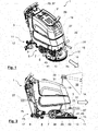
- the cleaning robot 1 comprises a housing 3, which is arranged on a chassis 5.
- the chassis 5 has a drive which is connected to the wheels 7.
- the wheels 7 are independent from each other driven about an axis which extends parallel to a surface 8 to be cleaned. In order to change the direction of movement of the cleaning robot 1, the wheels 7 can be driven at different speeds or directions of rotation.
- two further wheels 9 are rotatably supported about a vertical axis. The vertical axis is perpendicular to the surface to be cleaned. 8
- a cleaning device 11 is also arranged, which projects beyond the housing 3 to a first side 12 and in the direction of travel 14.
- the direction of travel 14 of the floor cleaning robot 1 is understood to mean the direction parallel to the tangent of the movement path of the floor cleaning robot 1 on the surface 8 to be cleaned in its forward direction of travel.
- the cleaning device 11 is designed as a brush head 13, 15 with a rotationally driven cleaning brush 13 and a cover 15.
- the brush head 13, 15 and thus the cleaning device 11 are arranged in the direction of travel 14 in front of the chassis 5 and partially in front of the housing 3 and can be moved relative to the housing 3 and the chassis 5 in height to the brush head 13, 15 and thus optionally, to bring the cleaning device 11 into engagement with the surface 8 to be cleaned.
- the cleaning device 11 also includes a receiving device 17 in the form of a Saugfu-ßes 17, with the dirt and dirty water from the surface to be cleaned 8 can be added.
- the liquid received by the receiving device 17 is collected in a dirty water tank 19 which is pivotally mounted in the housing.
- a cleaning liquid or a mixture of water and a cleaning liquid can be applied by way of a water feed arranged inside the brush head 13, 15.
- the floor cleaning robot 1 also has a control unit 23, shown schematically, which is set up to guide the floor cleaning robot 1 by means of a representation of the surface 8 to be cleaned.
- the control unit 23 can control the driving speed and the direction of travel 14 of the cleaning robot 1 and the use of the cleaning device 11 for this purpose.
- the control unit 23 can determine, for example, the speed and the direction with which the wheels 7 rotate and thus possibly change the direction of travel 14.
- the floor cleaning robot 1 can also be controlled manually by means of a handle 24 attached to the rear part of the housing 3, control elements for the drive being provided in the area of the handle 24 so that the robot can also be operated like a conventional floor cleaning machine.
- a plurality of ultrasonic and infrared sensors 25 are arranged on the housing 3. Each of these sensors 25 may determine the distance to a surface element that is in the solid angle 27 detected by the sensor 25. The distances to surface elements detected by the sensors 25 are transmitted to the control unit 23, which takes these into account when calculating the further travel path.
- the floor cleaning robot 1 also has a first and a second measuring device 29, 31 for three-dimensional distance measurement.
- the first measuring device 29 is configured to simultaneously detect or determine the distance of the measuring device 29 from a plurality of surface elements at a first solid angle 33.
- the second measuring device 31 is set up accordingly, the distance of the Measuring device 31 to detect a plurality of surface elements at a second solid angle 35.
- a three-dimensional distance measurement is understood as meaning the measurement of the distance from a multiplicity of surface elements of a surface, wherein at least one surface element of the surface directly adjoins more than two surface elements whose distance from the measuring device can be measured.
- a measuring device can detect not only a line-shaped arrangement of surface elements, but also a planar arrangement.
- each measuring device 29, 31 comprises a light source emitting, for example, light having a wavelength of approximately 830 nm.
- a light source that emits light with other wavelengths in the infrared range.
- the light emitted by the light sources illuminates the surface elements arranged in the respective solid angle 33, 35 with a grid and in this case a dot matrix.
- the grid can be generated for example by a film.
- the use of a light source in the infrared is advantageous because the cleaning robot is not dependent on sufficient external illumination of the surface to be cleaned 8, but at the same time also does not emit light that could dazzle a person.
- the measuring devices 29, 31 also have a camera with which light reflected by surface elements in the respective solid angle 33, 35, which has previously been emitted by the respective light source, can be recorded.
- An evaluation device which is also provided in the measuring device 29, 31, calculates from the raster reflected by the surface elements Distance of the measuring devices 29, 31 to the surface elements.
- Such a measuring device 29, 31 is marketed, for example, under the name Kinect® by Microsoft®.
- the light sources of the first measuring device 29 and the light source of the second measuring device 31 are preferably pulsed, and the light source of the first measuring device 29 is correlated with the light source of the second measuring device 31 in such a way that the light source of the first measuring device 29 does not emit light when the light source the second measuring device 31 emits light. In this way it can be ensured that only one light source currently emits light. This reliably prevents the grid of the light sources from overlapping and erroneous distance measurements being made.
- the first and second solid angles 33, 35 have the same extent perpendicular to the surface 8 to be cleaned.
- the measuring devices 29, 31 are inclined at an identical vertical extent of the solid angles 33, 35 at the same angle to the surface 8 to be cleaned.
- the solid angles 33, 35 are horizontally adjacent, but overlap as in FIG. 3 can be seen in plan view is not, and are offset from each other. In this way, the rasters of the first and second measuring devices 29, 31 do not advantageously interfere, ie the raster generated by the first measuring device 29 is not detected by the second measuring device 31 and vice versa.
- the first measuring device 29 is arranged such that the direction of travel 14 runs through the first solid angle 33.
- the measuring devices 29, 31 can also each have, for example, a further camera for recording radiation in the visible spectral range. Among other things, the data from these cameras could be used to classify obstacles more accurately.
- the first measuring device 29 is thus aligned such that it detects surface elements which are arranged in the lane 36 of the floor cleaning robot 1 and on a first side 12 of the floor cleaning robot 1.
- Under the track or the lane 36 of the floor cleaning robot 1 should be understood here the area of the surface to be cleaned 8, which is determined by the projection of the housing 3 on the surface to be cleaned 8 in a rectilinear motion of the robot 1 along its current direction of travel 14.
- the second measuring device 31 is further aligned such that it only detects surface elements of the surface 8 to be cleaned, which are arranged outside the lane 36 and on the side facing away from the first side 12 of the floor cleaning robot 1.
- the second measuring device 31 is oriented such that the second solid angle 35 lies on the side of the floor cleaning robot 1 facing away from the first side 12, is arranged outside of its lane 36 and the lane 36 does not intersect the second solid angle 35.
- the solid angles 33, 35, under which the first and the second measuring device 29, 31 detect the surface 8 to be cleaned, are aligned perpendicular to the surface 8 to be cleaned in such a way that sufficient obstacles are detected in the travel path 36 on the entire height of the cleaning robot 1 In order to avoid collisions with such obstacles, but as far as possible no obstacles are detected under which the cleaning robot 1 can drive through.
- the measuring devices 29, 31 are further aligned so that the surface 8 to be cleaned with the highest resolution at a distance of about one to three meters in the direction of travel 14 in front of the cleaning robot 1 are detected.
- the arrangement of the first and the second measuring device 29, 31 thus allows a particularly detailed detection of the environment of the floor cleaning robot 1.
- the second measuring device is used in particular to detect the turning region of the cleaning robot 1. Due to the arrangement of the cleaning device 11, this moves past primarily with the first side 12 close to walls or other objects and thus inevitably turns primarily in the direction of the first side 12 opposite side.
- the control unit 23 is designed to guide the cleaning robot 1 over the surface 8 to be cleaned by means of a representation of the surface 8 to be cleaned and to clean the surface 8.
- the representation of the surface 8 can be done for example in the form of a map.
- This card can be made available to the cleaning robot 1 before the cleaning process.
- the cleaning robot 1 uses the distances to surface elements detected by the three-dimensional distance measurement measuring devices 29, 31 and the sensors 25 to continuously update the representation of the surface 8 so as to adapt to changes in the surface.
- the representation of the surface 8 can also be generated or generated automatically by the control unit 23 from the distances and positions detected in space by the measuring devices 29, 31.
- the card can be stored in any file format in a memory of the control unit 23.
- the control unit 23 has a gyroscope 37 with which rotations of the cleaning robot 1 about the vertical axis can be measured.
- the wheels 7 have an encoder 39, which measures the number of revolutions of the wheels 7 and thus the distance traveled by the cleaning robot 1.
- the control unit 23 is configured to use the data recorded by the gyroscope 37 and the encoder 39 together with to determine the position and orientation of the floor cleaning robot 1 in the representation of the surface to be cleaned 8 with the measuring devices 29, 31.
- the floor cleaning robot 1 also has an underrun protection device 41 and two side gap measuring devices 43, 45.
- the underrun protection device 41 and the side gap measuring device 43, 45 represent independent inventive concepts. Both concepts are not limited to use in floor cleaning robots, but can generally be used in floor cleaning machines with a chassis, possibly with a drive, and a mounted on the chassis cleaning device ,
- an underrun protection device 41 is arranged on the cover 15 of the brush head 13.
- This comprises a device for distance measurement in the form of an ultrasonic sensor 49, which is aligned substantially perpendicular to the surface 8 to be cleaned.
- the orientation of the ultrasonic sensor 49 refers to the direction in which the ultrasonic sensor 49 emits an ultrasonic field 51.
- the ultrasonic sensor 49 is arranged at a point of the floor cleaning machine, which is parallel to the direction of travel 14 of the floor cleaning robot 1 in front of the housing 3.
- the ultrasonic sensor 49 detects surface elements that are located in the travel path 36 of the cleaning robot 1.
- the underrun protection device 41 may be connected to the control device 23, which integrates the distance of a surface element detected by the ultrasonic sensor 49 into the representation of the surface 8 to be cleaned and takes into account when guiding the floor cleaning robot 1.
- the underrun protection 41 is an independent inventive concept which can also be used on other floor cleaning robots or floor cleaning machines which, for example, have no cover 15 of the brush head 13, 15 projecting beyond the housing 3.
- the underrun protection 41 is arranged in this case on an element of the floor cleaning robot, which is arranged as close as possible to the surface 8 to be cleaned and the housing 3 in a plane parallel to the surface to be cleaned 8 surmounted.
- the floor cleaning robot 1 also has on the cover 15 of the brush head 13, 15 two side distance measuring device 43, 45 on.
- Each lateral distance measuring device 43, 45 comprises a device for determining a distance from a surface element in the form of an ultrasonic sensor 53, 55.
- the ultrasonic sensors 53, 55 are aligned such that the ultrasonic field emitted by them in an opening cone 57, 59 is substantially parallel to the cleaning surface 8 and perpendicular to the direction of travel 14 is emitted.
- the ultrasonic sensors 53, 55 can thus determine the distance of the floor cleaning robot 1 to a parallel to the direction of travel 14 extending surface such as a wall or a shelf.
- the ultrasonic sensors 53, 55 are arranged on the cover 15 of the brush head 13, 15, they are only a few centimeters above the surface to be cleaned 8 and are particularly advantageous manner to bring the floor cleaning robot 1 particularly close to walls and, for example, baseboards and to ensure a thorough and complete cleaning of the surface 8.
- a device for distance measurement 53, 55 can be used which has a special narrow opening cone 59 or which can detect a surface element in a particularly narrow solid angle. These opening cones 57, 59 are aligned so that they only meet outside of the largest detectable by the sensor distance and more preferably not on the surface to be cleaned 8.
- the side distance measuring device 43, 45 according to the invention can thus detect surface elements that are arranged only slightly above the floor to be cleaned 8, such as baseboards on walls, so that the floor cleaning robot 1 can zoom particularly close to walls. It avoids the disadvantages of devices for distance measurement, which have a wide opening angle and have a pointing to the bottom opening angle. Such devices often erroneously detect already extremely flat elevations on the surface to be cleaned 8 or even depressions such as joints, which can actually run over the floor cleaning machine easily and thus prevent complete cleaning of the entire surface to be cleaned. 8
- the lateral distance measurement is characterized by the arrangement of the lateral distance measuring devices 43, 45 directly on the brush head 13, 15, which overhangs the floor cleaning machine or the cleaning robot 1 itself mostly perpendicular to the direction of travel 14 and is arranged as close to the ground.
- the devices 43, 45 are on the brush head 13, 15 undoubtedly exposed to greater vibration than would be the case with an arrangement on the housing 3 of a floor cleaning machine. On the whole, however, the advantages outweigh the advantages of the ground-level arrangement of the devices 43, 45.
- the embodiment of the floor cleaning robot 1 according to the invention has been described with reference to a floor cleaning machine described, the alternative to autonomous driving can also be operated by a person who goes behind the floor cleaning machine ago.
- the invention is not limited to such floor cleaning machines. It can be easily extended to floor cleaning machines on which the operator sits or is or mittool so particular ride-on machines.
Landscapes
- Engineering & Computer Science (AREA)
- Physics & Mathematics (AREA)
- Radar, Positioning & Navigation (AREA)
- Remote Sensing (AREA)
- Aviation & Aerospace Engineering (AREA)
- General Physics & Mathematics (AREA)
- Automation & Control Theory (AREA)
- Electromagnetism (AREA)
- Computer Vision & Pattern Recognition (AREA)
- Multimedia (AREA)
- Control Of Position, Course, Altitude, Or Attitude Of Moving Bodies (AREA)
- Electric Vacuum Cleaner (AREA)
Claims (15)
- Robot de nettoyage de sol (1) avec un boîtier (3),
avec un train de roulement (5) avec un entraînement pour le déplacement du robot de nettoyage de sol dans une direction de déplacement (14) au-dessus d'une surface à nettoyer (8),
avec un dispositif de nettoyage (11) conçu pour adhérer à la surface à nettoyer (8),
avec une unité de commande (23) et
avec un premier dispositif de mesure (29) pour une mesure de distance tridimensionnelle, conçu pour mesurer la distance entre le premier dispositif de mesure (29) et une pluralité d'éléments de surface, à l'intérieur d'un premier angle solide (33) qui part du premier dispositif de mesure (29),
l'unité de commande (23) étant conçue de façon à guider le robot de nettoyage de sol (1), à l'aide d'une représentation de la surface à nettoyer (8), au-dessus de la surface à nettoyer (8) et à nettoyer la surface à nettoyer (8), caractérisé en ce que
un deuxième dispositif de mesure (31) pour une mesure de distance tridimensionnelle est prévu, qui est conçu pour mesurer la distance entre le deuxième dispositif de mesure (31) et une pluralité d'éléments de surface à l'intérieur d'un deuxième angle solide (35) qui part du deuxième dispositif de mesure (31),
le premier dispositif de mesure (29) et le deuxième dispositif de mesure (31) sont conçus de façon à ce que la direction de déplacement (14) traverse le premier angle solide (33) et le deuxième angle solide (35) est décalé par rapport au premier angle solide (33) et
l'unité de commande (23) est conçue pour générer et/ou actualiser la représentation de la surface à nettoyer (8) sur la base des distances, déterminées avec les dispositifs de mesures (29, 31), par rapport aux éléments de surface. - Robot de nettoyage de sol (1) selon la revendication 1, caractérisé en ce que le dispositif de nettoyage (11) dépasse du boîtier (3) perpendiculairement à la direction de déplacement (14) et parallèlement à la surface à nettoyer (8), vers un premier côté (12), ou se termine avec celui-ci et
en ce que le deuxième dispositif de mesure (31) est conçu de façon à ce que le deuxième angle solide (35) est disposé sur le côté du robot de nettoyage de sol (1) opposé au premier côté (12), à l'extérieur de sa trajectoire de déplacement (36) et la trajectoire de déplacement (36) ne coupe pas le deuxième angle solide (35). - Robot de nettoyage de sol (1) selon la revendication 1 ou 2, caractérisé en ce que le premier et le deuxième dispositif de mesure (29, 31) comprennent une source de lumière, une caméra et un dispositif d'analyse,
en ce que la source de lumière émet une lumière avec une longueur d'onde entre 780 nm et 3000 nm et éclaire les éléments de surface disposé à l'intérieur de l'angle solide (33, 35) avec une trame,
en ce que la caméra enregistre la lumière réfléchie à l'intérieur de l'angle solide (33, 35) par les éléments de surface, qui est émise par la source de lumière et
en ce que le dispositif d'analyse est conçu pour déterminer, à partir de la trame réfléchie par les éléments de surface, la distance entre le dispositif de mesure (29, 31) et les éléments de surface. - Robot de nettoyage de sol (1) selon la revendication 3, caractérisé en ce que la source de lumière du premier dispositif de mesure (29) et la source de lumière du deuxième dispositif de mesure (31) sont pulsées et
en ce que la source de lumière du premier dispositif de mesure (29) est corrélée avec la source de lumière du deuxième dispositif de mesure (31) de façon à ce que la source de lumière du premier dispositif de mesure (29) ne puisse pas émettre de lumière lorsque que la source de lumière du deuxième dispositif de mesure (31) émet de la lumière. - Robot de nettoyage de sol (1) selon l'une des revendications précédentes, caractérisé en ce que le premier et le deuxième angle solide (33, 35) sont horizontalement voisins l'un de l'autre et ne se superposent pas.
- Robot de nettoyage de sol (1) selon l'une des revendications précédentes, caractérisé en ce que le dispositif de nettoyage (11) est disposé au moins partiellement avant le boîtier (3) dans la direction de déplacement et
en ce que le dispositif de nettoyage (11) comprend une protection (15) qui dépasse le boîtier parallèlement à une surface à nettoyer (8) dans la direction de déplacement (14) et/ou perpendiculairement à la direction de déplacement. - Robot de nettoyage de sol (1) selon la revendication 6, caractérisé en ce que le dispositif de nettoyage (11) comprend, en dessous de la protection (15), une ou plusieurs brosses rotatives.
- Robot de nettoyage de sol (1) selon la revendication 6 ou 7, caractérisé en ce qu'un dispositif anti-encastrement (41) est prévu sur la protection (15),
en ce que le dispositif anti-encastrement (41) comprend un dispositif de mesure de distance (49) permettant de mesurer la distance entre le dispositif anti-encastrement (41) et un élément de surface qui se trouve devant le boîtier (3) du robot de nettoyage de sol (1), dans la direction de déplacement (14) et
en ce que le dispositif anti-encastrement (41) est conçu pour envoyer un signal d'arrêt à l'unité de commande (23) ; - Robot de nettoyage de sol (1) selon la revendication 8, caractérisé en ce que la zone de mesure du dispositif de mesure de distance (49) est sensiblement perpendiculaire à la surface à nettoyer (8).
- Robot de nettoyage de sol (1) selon la revendication 8 ou 9, caractérisé en ce que le dispositif de mesure de distance (49) du dispositif anti-encastrement (41) est un capteur à ultrasons ou un capteur à infrarouge.
- Robot de nettoyage de sol (1) selon l'une des revendications 8 à 10, caractérisé en ce que le dispositif anti-encastrement (41) permet de mesurer la distance entre un élément de surface qui se trouve, lorsque le robot de nettoyage de sol (1) se rapproche au moins temporairement à l'intérieur d'une zone du premier ou du deuxième angle solide (33, 35), dans laquelle la distance par rapport au premier ou au deuxième dispositif de mesure (29, 31) est inférieure à une distance minimale que le premier ou le deuxième dispositif de mesure (29, 31) permet de déterminer.
- Robot de nettoyage de sol (1) selon l'une des revendications 6 à 11, caractérisé en ce que le robot de nettoyage de sol (1) comprend un ou plusieurs dispositifs de mesure de distance latérale (43, 45) qui se trouvent sur la protection (15) du dispositif de nettoyage (11) et
chaque dispositif de mesure de distance latérale (43, 45) permet de déterminer une distance du dispositif de nettoyage (11) perpendiculairement à la direction de déplacement (14) et parallèlement à la surface à nettoyer (8) par rapport à un élément de surface. - Robot de nettoyage de sol (1) selon l'une des revendications précédentes, caractérisé en ce que le robot de nettoyage de sol (1) comprend un gyroscope (37) et
en ce que le gyroscope (37) permet de mesurer une rotation du robot de nettoyage de sol (1) autour d'un axe qui est perpendiculaire à la surface à nettoyer (8). - Robot de nettoyage de sol (1) selon l'une des revendications précédentes, caractérisé en ce que le train de roulement (5) comprend un codeur (39) permettant de déterminer le trajet parcouru.
- Robot de nettoyage de sol (1) selon la revendication 14, dans la mesure où elle dépend de la revendication 13, l'unité de commande (23) étant conçue de façon à pouvoir déterminer une position du robot de nettoyage de sol (1) dans la représentation du sol à nettoyer (8) à l'aide des rotations mesurées avec le gyroscope (37) et avec les trajets déterminés avec le codeur (39).
Priority Applications (4)
| Application Number | Priority Date | Filing Date | Title |
|---|---|---|---|
| EP13154994.1A EP2764812B1 (fr) | 2013-02-12 | 2013-02-12 | Robot de nettoyage |
| DK13154994.1T DK2764812T3 (en) | 2013-02-12 | 2013-02-12 | Cleaning Robot. |
| US14/177,268 US9468352B2 (en) | 2013-02-12 | 2014-02-11 | Cleaning robot |
| CN201410049148.4A CN103976694B (zh) | 2013-02-12 | 2014-02-12 | 清洁机器人 |
Applications Claiming Priority (1)
| Application Number | Priority Date | Filing Date | Title |
|---|---|---|---|
| EP13154994.1A EP2764812B1 (fr) | 2013-02-12 | 2013-02-12 | Robot de nettoyage |
Publications (2)
| Publication Number | Publication Date |
|---|---|
| EP2764812A1 EP2764812A1 (fr) | 2014-08-13 |
| EP2764812B1 true EP2764812B1 (fr) | 2015-07-08 |
Family
ID=47683634
Family Applications (1)
| Application Number | Title | Priority Date | Filing Date |
|---|---|---|---|
| EP13154994.1A Active EP2764812B1 (fr) | 2013-02-12 | 2013-02-12 | Robot de nettoyage |
Country Status (4)
| Country | Link |
|---|---|
| US (1) | US9468352B2 (fr) |
| EP (1) | EP2764812B1 (fr) |
| CN (1) | CN103976694B (fr) |
| DK (1) | DK2764812T3 (fr) |
Cited By (2)
| Publication number | Priority date | Publication date | Assignee | Title |
|---|---|---|---|---|
| KR101938668B1 (ko) | 2017-05-29 | 2019-01-15 | 엘지전자 주식회사 | 청소기 및 그 제어방법 |
| WO2023001391A1 (fr) | 2021-07-23 | 2023-01-26 | Alfred Kärcher SE & Co. KG | Appareil de nettoyage de sol autopropulsé et à guidage automatique, et système de nettoyage de sol |
Families Citing this family (13)
| Publication number | Priority date | Publication date | Assignee | Title |
|---|---|---|---|---|
| DE102015105211A1 (de) * | 2015-04-07 | 2016-10-13 | Vorwerk & Co. Interholding Gmbh | Verfahren zur Bearbeitung eines Bodens |
| CN106137057B (zh) * | 2015-04-15 | 2018-10-19 | 小米科技有限责任公司 | 清洁机器人及机器人防碰撞方法 |
| CN106323230B (zh) * | 2015-06-30 | 2019-05-14 | 芋头科技(杭州)有限公司 | 一种障碍物识别装置及障碍物识别方法 |
| KR102445064B1 (ko) | 2015-09-03 | 2022-09-19 | 에이비 엘렉트로룩스 | 로봇 청소 장치의 시스템 |
| JP7007078B2 (ja) * | 2015-10-08 | 2022-01-24 | 東芝ライフスタイル株式会社 | 電気掃除機 |
| TWM521997U (zh) * | 2015-10-13 | 2016-05-21 | Lumiplus Technology Suzhou Co Ltd | 自走裝置之防掉落系統 |
| WO2019063066A1 (fr) | 2017-09-26 | 2019-04-04 | Aktiebolaget Electrolux | Commande de déplacement d'un dispositif de nettoyage robotique |
| CN109367522B (zh) * | 2018-10-19 | 2023-07-28 | 宁波大壬智能科技有限公司 | 一种洗车机器人 |
| CN112862199B (zh) * | 2020-05-11 | 2023-08-08 | 追觅创新科技(苏州)有限公司 | 清洁设备的清洁路径获取方法、装置及存储介质 |
| USD1000023S1 (en) * | 2020-10-14 | 2023-09-26 | Alfred Kaercher Se & Co. Kg | Machine for cleaning floors |
| CN112674653B (zh) * | 2020-12-29 | 2022-04-19 | 深圳市云鼠科技开发有限公司 | 障碍物位置标记方法、装置、计算机设备及存储介质 |
| USD1006355S1 (en) * | 2021-01-21 | 2023-11-28 | Alfred Kaercher Se & Co. Kg | Floor cleaning device |
| USD1043000S1 (en) * | 2023-01-31 | 2024-09-17 | FJ Dynamics International Limited | Cleaning robot |
Family Cites Families (15)
| Publication number | Priority date | Publication date | Assignee | Title |
|---|---|---|---|---|
| DE19614916A1 (de) * | 1996-04-16 | 1997-11-06 | Detlef Raupach | Fahrroboter für die automatische Behandlung von Bodenflächen |
| US6956348B2 (en) * | 2004-01-28 | 2005-10-18 | Irobot Corporation | Debris sensor for cleaning apparatus |
| US7571511B2 (en) * | 2002-01-03 | 2009-08-11 | Irobot Corporation | Autonomous floor-cleaning robot |
| US6667592B2 (en) | 2001-08-13 | 2003-12-23 | Intellibot, L.L.C. | Mapped robot system |
| US8428778B2 (en) * | 2002-09-13 | 2013-04-23 | Irobot Corporation | Navigational control system for a robotic device |
| US7135992B2 (en) | 2002-12-17 | 2006-11-14 | Evolution Robotics, Inc. | Systems and methods for using multiple hypotheses in a visual simultaneous localization and mapping system |
| US7805220B2 (en) * | 2003-03-14 | 2010-09-28 | Sharper Image Acquisition Llc | Robot vacuum with internal mapping system |
| US20060020369A1 (en) * | 2004-03-11 | 2006-01-26 | Taylor Charles E | Robot vacuum cleaner |
| US8392021B2 (en) * | 2005-02-18 | 2013-03-05 | Irobot Corporation | Autonomous surface cleaning robot for wet cleaning |
| EP2816434A3 (fr) * | 2005-12-02 | 2015-01-28 | iRobot Corporation | Robot à couverture autonome |
| DE102007015552B3 (de) * | 2007-03-29 | 2008-08-07 | Miele & Cie. Kg | Selbstfahrender Roboter zur Behandlung von Bodenflächen |
| EP2264560A1 (fr) * | 2009-06-02 | 2010-12-22 | Koninklijke Philips Electronics N.V. | Appareil doté d'un contrôle de boîtier lumineux en fonction de la couleur de son environnement |
| US8918209B2 (en) * | 2010-05-20 | 2014-12-23 | Irobot Corporation | Mobile human interface robot |
| DE102011004319A1 (de) | 2011-02-17 | 2012-08-23 | Robert Bosch Gmbh | Reinigungsroboter |
| US8958911B2 (en) * | 2012-02-29 | 2015-02-17 | Irobot Corporation | Mobile robot |
-
2013
- 2013-02-12 DK DK13154994.1T patent/DK2764812T3/en active
- 2013-02-12 EP EP13154994.1A patent/EP2764812B1/fr active Active
-
2014
- 2014-02-11 US US14/177,268 patent/US9468352B2/en active Active
- 2014-02-12 CN CN201410049148.4A patent/CN103976694B/zh not_active Expired - Fee Related
Cited By (2)
| Publication number | Priority date | Publication date | Assignee | Title |
|---|---|---|---|---|
| KR101938668B1 (ko) | 2017-05-29 | 2019-01-15 | 엘지전자 주식회사 | 청소기 및 그 제어방법 |
| WO2023001391A1 (fr) | 2021-07-23 | 2023-01-26 | Alfred Kärcher SE & Co. KG | Appareil de nettoyage de sol autopropulsé et à guidage automatique, et système de nettoyage de sol |
Also Published As
| Publication number | Publication date |
|---|---|
| US9468352B2 (en) | 2016-10-18 |
| EP2764812A1 (fr) | 2014-08-13 |
| US20140223675A1 (en) | 2014-08-14 |
| DK2764812T3 (en) | 2015-08-24 |
| CN103976694A (zh) | 2014-08-13 |
| CN103976694B (zh) | 2017-11-14 |
Similar Documents
| Publication | Publication Date | Title |
|---|---|---|
| EP2764812B1 (fr) | Robot de nettoyage | |
| EP3139806B1 (fr) | Dispositif de nettoyage de sol roulant et manoeuvrant de manière autonome et méthode de nettoyage d'une surface de sol | |
| DE102016209576B4 (de) | Bewegungssteuerung für ein mobiles Medizingerät | |
| EP3587220B1 (fr) | Véhicule comprenant un système de manoeuvre | |
| EP2407847B1 (fr) | Appareil automobile et procédé d'orientation d'un tel appareil | |
| WO2016120044A1 (fr) | Mesure d'une dimension sur une surface | |
| EP1929389B1 (fr) | Procédé permettant de faire fonctionner un appareil électroménager à déplacement autonome et procédé permettant de faire fonctionner une station de base | |
| EP2755101B1 (fr) | Robot automoteur et procédé de détermination de distance pour un robot automoteur | |
| EP2479584B1 (fr) | Procédé de détermination de la position d'un appareil automobile | |
| EP3392738B1 (fr) | Procédé de fonctionnement d'un véhicule en mouvement de manière automatique | |
| DE10200394A1 (de) | Reinigungsroboter sowie diesen verwendendes System und Verfahren zur Wiederverbindung mit einer externen Nachladevorrichtung | |
| EP3709853A1 (fr) | Traitement du sol au moyen d'un robot mobile autonome | |
| EP3355147B1 (fr) | Procédé de fonctionnement d'un véhicule en mouvement de manière automatique | |
| DE102009041362A1 (de) | Verfahren zum Betreiben eines Reinigungsroboters | |
| EP3791105B1 (fr) | Dispositif et procédé pour sécuriser un appareil mobile à commande mécanique ou automatique et carreau de capteurs | |
| EP3412186A1 (fr) | Procédé de fonctionnement d'un appareil de traitement du sol mobile automatique | |
| EP3559770B1 (fr) | Procédé de fonctionnement d'un appareil de nettoyage à déplacement automatique ainsi qu'un tel appareil de nettoyage | |
| WO2016180414A1 (fr) | Dispositif pour déterminer un espace dans lequel un véhicule peut entrer, procédé correspondant et véhicule associé | |
| EP3453672A1 (fr) | Procédé et dispositif de prévention de collision lors du fonctionnement d'un chariot de manutention | |
| EP0378528A1 (fr) | Procede pour guider un vehicule automoteur et vehicule automoteur. | |
| DE102009003748B4 (de) | Bodenstaub-Aufsammelgerät sowie Verfahren eines solchen Geräts | |
| WO2018115153A1 (fr) | Procédé de navigation et localisation automatique d'un appareil d'usinage à déplacement autonome | |
| DE102010021042A1 (de) | Verfahren zur rechnergestützten Spurführung von Fahrzeugen | |
| DE10323643A1 (de) | Sensorsystem für ein autonomes Flurförderfahrzeug | |
| DE102018103835B3 (de) | Bodenbearbeitungsmaschine, insbesondere Bodenreinigungsmaschine |
Legal Events
| Date | Code | Title | Description |
|---|---|---|---|
| PUAI | Public reference made under article 153(3) epc to a published international application that has entered the european phase |
Free format text: ORIGINAL CODE: 0009012 |
|
| 17P | Request for examination filed |
Effective date: 20130212 |
|
| AK | Designated contracting states |
Kind code of ref document: A1 Designated state(s): AL AT BE BG CH CY CZ DE DK EE ES FI FR GB GR HR HU IE IS IT LI LT LU LV MC MK MT NL NO PL PT RO RS SE SI SK SM TR |
|
| AX | Request for extension of the european patent |
Extension state: BA ME |
|
| R17P | Request for examination filed (corrected) |
Effective date: 20140902 |
|
| RBV | Designated contracting states (corrected) |
Designated state(s): AL AT BE BG CH CY CZ DE DK EE ES FI FR GB GR HR HU IE IS IT LI LT LU LV MC MK MT NL NO PL PT RO RS SE SI SK SM TR |
|
| GRAP | Despatch of communication of intention to grant a patent |
Free format text: ORIGINAL CODE: EPIDOSNIGR1 |
|
| INTG | Intention to grant announced |
Effective date: 20150206 |
|
| GRAS | Grant fee paid |
Free format text: ORIGINAL CODE: EPIDOSNIGR3 |
|
| GRAA | (expected) grant |
Free format text: ORIGINAL CODE: 0009210 |
|
| AK | Designated contracting states |
Kind code of ref document: B1 Designated state(s): AL AT BE BG CH CY CZ DE DK EE ES FI FR GB GR HR HU IE IS IT LI LT LU LV MC MK MT NL NO PL PT RO RS SE SI SK SM TR |
|
| REG | Reference to a national code |
Ref country code: GB Ref legal event code: FG4D Free format text: NOT ENGLISH |
|
| RIN1 | Information on inventor provided before grant (corrected) |
Inventor name: BAVENDIEK, RAINER Inventor name: ZIMNY, AXEL Inventor name: FOROUHER, DARIUSH Inventor name: KLUESSENDORFF, JAN HELGE |
|
| REG | Reference to a national code |
Ref country code: SE Ref legal event code: TRGR |
|
| REG | Reference to a national code |
Ref country code: AT Ref legal event code: REF Ref document number: 734713 Country of ref document: AT Kind code of ref document: T Effective date: 20150715 Ref country code: CH Ref legal event code: EP |
|
| REG | Reference to a national code |
Ref country code: IE Ref legal event code: FG4D Free format text: LANGUAGE OF EP DOCUMENT: GERMAN |
|
| REG | Reference to a national code |
Ref country code: DE Ref legal event code: R096 Ref document number: 502013000830 Country of ref document: DE |
|
| REG | Reference to a national code |
Ref country code: DK Ref legal event code: T3 Effective date: 20150817 |
|
| REG | Reference to a national code |
Ref country code: NL Ref legal event code: MP Effective date: 20150708 |
|
| REG | Reference to a national code |
Ref country code: LT Ref legal event code: MG4D |
|
| REG | Reference to a national code |
Ref country code: FR Ref legal event code: PLFP Year of fee payment: 4 |
|
| PG25 | Lapsed in a contracting state [announced via postgrant information from national office to epo] |
Ref country code: NO Free format text: LAPSE BECAUSE OF FAILURE TO SUBMIT A TRANSLATION OF THE DESCRIPTION OR TO PAY THE FEE WITHIN THE PRESCRIBED TIME-LIMIT Effective date: 20151008 Ref country code: GR Free format text: LAPSE BECAUSE OF FAILURE TO SUBMIT A TRANSLATION OF THE DESCRIPTION OR TO PAY THE FEE WITHIN THE PRESCRIBED TIME-LIMIT Effective date: 20151009 Ref country code: LT Free format text: LAPSE BECAUSE OF FAILURE TO SUBMIT A TRANSLATION OF THE DESCRIPTION OR TO PAY THE FEE WITHIN THE PRESCRIBED TIME-LIMIT Effective date: 20150708 Ref country code: LV Free format text: LAPSE BECAUSE OF FAILURE TO SUBMIT A TRANSLATION OF THE DESCRIPTION OR TO PAY THE FEE WITHIN THE PRESCRIBED TIME-LIMIT Effective date: 20150708 Ref country code: FI Free format text: LAPSE BECAUSE OF FAILURE TO SUBMIT A TRANSLATION OF THE DESCRIPTION OR TO PAY THE FEE WITHIN THE PRESCRIBED TIME-LIMIT Effective date: 20150708 |
|
| PG25 | Lapsed in a contracting state [announced via postgrant information from national office to epo] |
Ref country code: ES Free format text: LAPSE BECAUSE OF FAILURE TO SUBMIT A TRANSLATION OF THE DESCRIPTION OR TO PAY THE FEE WITHIN THE PRESCRIBED TIME-LIMIT Effective date: 20150708 Ref country code: PL Free format text: LAPSE BECAUSE OF FAILURE TO SUBMIT A TRANSLATION OF THE DESCRIPTION OR TO PAY THE FEE WITHIN THE PRESCRIBED TIME-LIMIT Effective date: 20150708 Ref country code: HR Free format text: LAPSE BECAUSE OF FAILURE TO SUBMIT A TRANSLATION OF THE DESCRIPTION OR TO PAY THE FEE WITHIN THE PRESCRIBED TIME-LIMIT Effective date: 20150708 Ref country code: RS Free format text: LAPSE BECAUSE OF FAILURE TO SUBMIT A TRANSLATION OF THE DESCRIPTION OR TO PAY THE FEE WITHIN THE PRESCRIBED TIME-LIMIT Effective date: 20150708 Ref country code: IS Free format text: LAPSE BECAUSE OF FAILURE TO SUBMIT A TRANSLATION OF THE DESCRIPTION OR TO PAY THE FEE WITHIN THE PRESCRIBED TIME-LIMIT Effective date: 20151108 Ref country code: PT Free format text: LAPSE BECAUSE OF FAILURE TO SUBMIT A TRANSLATION OF THE DESCRIPTION OR TO PAY THE FEE WITHIN THE PRESCRIBED TIME-LIMIT Effective date: 20151109 |
|
| REG | Reference to a national code |
Ref country code: DE Ref legal event code: R097 Ref document number: 502013000830 Country of ref document: DE |
|
| PG25 | Lapsed in a contracting state [announced via postgrant information from national office to epo] |
Ref country code: CZ Free format text: LAPSE BECAUSE OF FAILURE TO SUBMIT A TRANSLATION OF THE DESCRIPTION OR TO PAY THE FEE WITHIN THE PRESCRIBED TIME-LIMIT Effective date: 20150708 Ref country code: EE Free format text: LAPSE BECAUSE OF FAILURE TO SUBMIT A TRANSLATION OF THE DESCRIPTION OR TO PAY THE FEE WITHIN THE PRESCRIBED TIME-LIMIT Effective date: 20150708 Ref country code: SK Free format text: LAPSE BECAUSE OF FAILURE TO SUBMIT A TRANSLATION OF THE DESCRIPTION OR TO PAY THE FEE WITHIN THE PRESCRIBED TIME-LIMIT Effective date: 20150708 |
|
| PLBE | No opposition filed within time limit |
Free format text: ORIGINAL CODE: 0009261 |
|
| STAA | Information on the status of an ep patent application or granted ep patent |
Free format text: STATUS: NO OPPOSITION FILED WITHIN TIME LIMIT |
|
| PG25 | Lapsed in a contracting state [announced via postgrant information from national office to epo] |
Ref country code: RO Free format text: LAPSE BECAUSE OF FAILURE TO SUBMIT A TRANSLATION OF THE DESCRIPTION OR TO PAY THE FEE WITHIN THE PRESCRIBED TIME-LIMIT Effective date: 20150708 Ref country code: BE Free format text: LAPSE BECAUSE OF NON-PAYMENT OF DUE FEES Effective date: 20160229 |
|
| 26N | No opposition filed |
Effective date: 20160411 |
|
| PG25 | Lapsed in a contracting state [announced via postgrant information from national office to epo] |
Ref country code: SI Free format text: LAPSE BECAUSE OF FAILURE TO SUBMIT A TRANSLATION OF THE DESCRIPTION OR TO PAY THE FEE WITHIN THE PRESCRIBED TIME-LIMIT Effective date: 20150708 |
|
| PG25 | Lapsed in a contracting state [announced via postgrant information from national office to epo] |
Ref country code: LU Free format text: LAPSE BECAUSE OF FAILURE TO SUBMIT A TRANSLATION OF THE DESCRIPTION OR TO PAY THE FEE WITHIN THE PRESCRIBED TIME-LIMIT Effective date: 20160212 Ref country code: MC Free format text: LAPSE BECAUSE OF FAILURE TO SUBMIT A TRANSLATION OF THE DESCRIPTION OR TO PAY THE FEE WITHIN THE PRESCRIBED TIME-LIMIT Effective date: 20150708 |
|
| REG | Reference to a national code |
Ref country code: CH Ref legal event code: PL |
|
| PG25 | Lapsed in a contracting state [announced via postgrant information from national office to epo] |
Ref country code: CH Free format text: LAPSE BECAUSE OF NON-PAYMENT OF DUE FEES Effective date: 20160229 Ref country code: LI Free format text: LAPSE BECAUSE OF NON-PAYMENT OF DUE FEES Effective date: 20160229 |
|
| REG | Reference to a national code |
Ref country code: IE Ref legal event code: MM4A |
|
| REG | Reference to a national code |
Ref country code: FR Ref legal event code: PLFP Year of fee payment: 5 |
|
| PG25 | Lapsed in a contracting state [announced via postgrant information from national office to epo] |
Ref country code: IE Free format text: LAPSE BECAUSE OF NON-PAYMENT OF DUE FEES Effective date: 20160212 |
|
| PG25 | Lapsed in a contracting state [announced via postgrant information from national office to epo] |
Ref country code: NL Free format text: LAPSE BECAUSE OF FAILURE TO SUBMIT A TRANSLATION OF THE DESCRIPTION OR TO PAY THE FEE WITHIN THE PRESCRIBED TIME-LIMIT Effective date: 20150708 |
|
| PG25 | Lapsed in a contracting state [announced via postgrant information from national office to epo] |
Ref country code: MT Free format text: LAPSE BECAUSE OF FAILURE TO SUBMIT A TRANSLATION OF THE DESCRIPTION OR TO PAY THE FEE WITHIN THE PRESCRIBED TIME-LIMIT Effective date: 20150708 |
|
| REG | Reference to a national code |
Ref country code: FR Ref legal event code: PLFP Year of fee payment: 6 |
|
| PG25 | Lapsed in a contracting state [announced via postgrant information from national office to epo] |
Ref country code: CY Free format text: LAPSE BECAUSE OF FAILURE TO SUBMIT A TRANSLATION OF THE DESCRIPTION OR TO PAY THE FEE WITHIN THE PRESCRIBED TIME-LIMIT Effective date: 20150708 Ref country code: SM Free format text: LAPSE BECAUSE OF FAILURE TO SUBMIT A TRANSLATION OF THE DESCRIPTION OR TO PAY THE FEE WITHIN THE PRESCRIBED TIME-LIMIT Effective date: 20150708 Ref country code: HU Free format text: LAPSE BECAUSE OF FAILURE TO SUBMIT A TRANSLATION OF THE DESCRIPTION OR TO PAY THE FEE WITHIN THE PRESCRIBED TIME-LIMIT; INVALID AB INITIO Effective date: 20130212 |
|
| PG25 | Lapsed in a contracting state [announced via postgrant information from national office to epo] |
Ref country code: TR Free format text: LAPSE BECAUSE OF FAILURE TO SUBMIT A TRANSLATION OF THE DESCRIPTION OR TO PAY THE FEE WITHIN THE PRESCRIBED TIME-LIMIT Effective date: 20150708 Ref country code: MK Free format text: LAPSE BECAUSE OF FAILURE TO SUBMIT A TRANSLATION OF THE DESCRIPTION OR TO PAY THE FEE WITHIN THE PRESCRIBED TIME-LIMIT Effective date: 20150708 |
|
| PG25 | Lapsed in a contracting state [announced via postgrant information from national office to epo] |
Ref country code: BG Free format text: LAPSE BECAUSE OF FAILURE TO SUBMIT A TRANSLATION OF THE DESCRIPTION OR TO PAY THE FEE WITHIN THE PRESCRIBED TIME-LIMIT Effective date: 20150708 |
|
| PG25 | Lapsed in a contracting state [announced via postgrant information from national office to epo] |
Ref country code: AL Free format text: LAPSE BECAUSE OF FAILURE TO SUBMIT A TRANSLATION OF THE DESCRIPTION OR TO PAY THE FEE WITHIN THE PRESCRIBED TIME-LIMIT Effective date: 20150708 |
|
| REG | Reference to a national code |
Ref country code: AT Ref legal event code: MM01 Ref document number: 734713 Country of ref document: AT Kind code of ref document: T Effective date: 20180212 |
|
| PG25 | Lapsed in a contracting state [announced via postgrant information from national office to epo] |
Ref country code: AT Free format text: LAPSE BECAUSE OF NON-PAYMENT OF DUE FEES Effective date: 20180212 |
|
| PGFP | Annual fee paid to national office [announced via postgrant information from national office to epo] |
Ref country code: GB Payment date: 20220113 Year of fee payment: 10 Ref country code: DK Payment date: 20220209 Year of fee payment: 10 |
|
| PGFP | Annual fee paid to national office [announced via postgrant information from national office to epo] |
Ref country code: SE Payment date: 20220110 Year of fee payment: 10 Ref country code: IT Payment date: 20220111 Year of fee payment: 10 Ref country code: FR Payment date: 20220118 Year of fee payment: 10 |
|
| PGFP | Annual fee paid to national office [announced via postgrant information from national office to epo] |
Ref country code: DE Payment date: 20230110 Year of fee payment: 11 |
|
| REG | Reference to a national code |
Ref country code: DK Ref legal event code: EBP Effective date: 20230228 |
|
| REG | Reference to a national code |
Ref country code: SE Ref legal event code: EUG |
|
| GBPC | Gb: european patent ceased through non-payment of renewal fee |
Effective date: 20230212 |
|
| PG25 | Lapsed in a contracting state [announced via postgrant information from national office to epo] |
Ref country code: SE Free format text: LAPSE BECAUSE OF NON-PAYMENT OF DUE FEES Effective date: 20230213 |
|
| PG25 | Lapsed in a contracting state [announced via postgrant information from national office to epo] |
Ref country code: GB Free format text: LAPSE BECAUSE OF NON-PAYMENT OF DUE FEES Effective date: 20230212 |
|
| PG25 | Lapsed in a contracting state [announced via postgrant information from national office to epo] |
Ref country code: IT Free format text: LAPSE BECAUSE OF NON-PAYMENT OF DUE FEES Effective date: 20230212 Ref country code: GB Free format text: LAPSE BECAUSE OF NON-PAYMENT OF DUE FEES Effective date: 20230212 Ref country code: FR Free format text: LAPSE BECAUSE OF NON-PAYMENT OF DUE FEES Effective date: 20230228 Ref country code: DK Free format text: LAPSE BECAUSE OF NON-PAYMENT OF DUE FEES Effective date: 20230228 |