EP2762670A2 - Window system with an air outlet - Google Patents
Window system with an air outlet Download PDFInfo
- Publication number
- EP2762670A2 EP2762670A2 EP20140153579 EP14153579A EP2762670A2 EP 2762670 A2 EP2762670 A2 EP 2762670A2 EP 20140153579 EP20140153579 EP 20140153579 EP 14153579 A EP14153579 A EP 14153579A EP 2762670 A2 EP2762670 A2 EP 2762670A2
- Authority
- EP
- European Patent Office
- Prior art keywords
- window
- air outlet
- frame
- flashing
- height
- Prior art date
- Legal status (The legal status is an assumption and is not a legal conclusion. Google has not performed a legal analysis and makes no representation as to the accuracy of the status listed.)
- Withdrawn
Links
- 238000007789 sealing Methods 0.000 claims abstract description 9
- 239000002184 metal Substances 0.000 claims description 6
- 238000009434 installation Methods 0.000 description 15
- 238000009423 ventilation Methods 0.000 description 4
- 230000000295 complement effect Effects 0.000 description 2
- 238000004519 manufacturing process Methods 0.000 description 2
- 230000004048 modification Effects 0.000 description 2
- 238000012986 modification Methods 0.000 description 2
- 238000000034 method Methods 0.000 description 1
- 230000035515 penetration Effects 0.000 description 1
- 238000001556 precipitation Methods 0.000 description 1
- XLYOFNOQVPJJNP-UHFFFAOYSA-N water Substances O XLYOFNOQVPJJNP-UHFFFAOYSA-N 0.000 description 1
Images


Classifications
-
- E—FIXED CONSTRUCTIONS
- E06—DOORS, WINDOWS, SHUTTERS, OR ROLLER BLINDS IN GENERAL; LADDERS
- E06B—FIXED OR MOVABLE CLOSURES FOR OPENINGS IN BUILDINGS, VEHICLES, FENCES OR LIKE ENCLOSURES IN GENERAL, e.g. DOORS, WINDOWS, BLINDS, GATES
- E06B7/00—Special arrangements or measures in connection with doors or windows
- E06B7/02—Special arrangements or measures in connection with doors or windows for providing ventilation, e.g. through double windows; Arrangement of ventilation roses
- E06B7/04—Special arrangements or measures in connection with doors or windows for providing ventilation, e.g. through double windows; Arrangement of ventilation roses with ventilation wings
-
- E—FIXED CONSTRUCTIONS
- E04—BUILDING
- E04D—ROOF COVERINGS; SKY-LIGHTS; GUTTERS; ROOF-WORKING TOOLS
- E04D13/00—Special arrangements or devices in connection with roof coverings; Protection against birds; Roof drainage ; Sky-lights
- E04D13/03—Sky-lights; Domes; Ventilating sky-lights
- E04D13/0325—Sky-lights; Domes; Ventilating sky-lights provided with ventilating means
-
- F—MECHANICAL ENGINEERING; LIGHTING; HEATING; WEAPONS; BLASTING
- F24—HEATING; RANGES; VENTILATING
- F24F—AIR-CONDITIONING; AIR-HUMIDIFICATION; VENTILATION; USE OF AIR CURRENTS FOR SCREENING
- F24F13/00—Details common to, or for air-conditioning, air-humidification, ventilation or use of air currents for screening
- F24F13/08—Air-flow control members, e.g. louvres, grilles, flaps or guide plates
- F24F13/18—Air-flow control members, e.g. louvres, grilles, flaps or guide plates specially adapted for insertion in flat panels, e.g. in door or window-pane
Definitions
- the present invention relates to a window system with an air outlet, the system consisting of multiple windows, particularly roof windows, each window having dimensions corresponding to a predefined size belonging to standard size series offered by a manufacturer.
- the air outlet functions basically as a duct conveying fresh air to rooms.
- air outlets are used in exterior wall windows, however in case of attics, where most often roof windows are the only windows, a need for air outlets built-in into the structure of the roof window has arisen.
- Air outlets installed in the window structure are a natural solution, because of relative ease of their manufacturing and installation. In this case, making additional air outlet openings in the exterior wall or in the roof is not necessary.
- Patent Application No. WO 03/001017 A1 An example of the air outlet built-in into the frame of a casement is shown in Patent Application No. WO 03/001017 A1 .
- the main element of this solution is a circular rotary ventilation valve installed in an opening made in the installation strip being a part of the top casement frame.
- the air duct is formed by the said ventilation valve and the space defined by the walls of the casement frame from one side and by the window frame walls from the other side.
- a disadvantage of this solution consists in a significant reduction of the window clearance accompanied by a small size of the ventilation duct.
- the rest of the installation strip is not used.
- this solution is hard to use in roof windows because of a lack of protection from weather conditions.
- a similar idea is constituted by an air outlet proposed in Patent Application No. WO 2005038165 A1 .
- a ventilation opening in the installation strip being a part of the window casement is closed by a flap valve, and the air supply duct is profiled in a way preventing penetration of water from the typical direction of precipitation.
- This solution is suitable both for exterior wall windows and roof windows.
- a window system which contains at least one window of predefined size, containing partially components of a window with one size, and partially one or more components of a window of another type in the given size range.
- This solution allows for installing, e.g. two different windows with standard sizes jointly in one window opening with dimensions included in the dimensional range of the window system.
- the solution proposed according to the invention introduces a possibility to install the window and the air outlet in a window system with various sizes, without any interference into the window structure.
- the distinguishing feature of the invention consists in a window system basically composed of windows with standard manufacturer's sizes, and air outlets being separate elements, installed optionally beside the window.
- An air outlet, installed beside the external surface of the window frame, intended basically for mounting on the reveal of the window opening, has the shape and external dimensions chosen in a way enabling its application in the said window system.
- the set composed of air outlets and multiple windows with interrelated sizes forms the window system, which enables the user to choose from a series of solutions with regard both to functions and sizes.
- the size of a rectangular windows is basically defined by two dimensions - width S and height W, most often reported in the form of SxW product. Moreover, depth G is also an important dimension. It is preferably the same or close for all windows and air outlets in the window system.
- one air outlet is installed in the set, however the system allows for installing a higher number of air outlets side by side, if need be.
- a base window without the air outlet (with standard dimensions from the manufacturer's dimensional series), as well as a set in the form of the air outlet and a smaller system window from the same manufacturer's dimensional series, maintaining total external dimensions preferably equal to dimensions of the base window without the air outlet.
- the first case comprises a solution with an air outlet installed beside the external surface of the frame top member.
- the second case comprises a solution with an air outlet installed beside the external surface of the frame bottom member.
- the third case comprises a solution with an air outlet installed beside the external surface of one of the frame side members.
- top air outlet In the first case, wherein the top air outlet is mounted beside the frame top member, its total length Ln is preferably equal to width Sb of the base window. Width Ss of the system window is preferably equal to width Sb of the base window. Depth G of the top air outlet may be defined freely within the framework of the selected sheet metal flashing of the window, however preferably it is equal to the depth G of the system window. Height Wn of the top air outlet is an element of the proposed window system and this dimension is preferably a difference between the height Wb of the base window from the manufacturer's dimensional series and the height Ws of the next system window with smaller height from the same dimensional series.
- the bottom air outlet is mounted beside the frame bottom member
- its total length Ln is preferably equal to width Sb of the base window.
- Width Ss of the system window is preferably equal to width Sb of the base window.
- this case is similar to the first case, i.e. depth G of the air outlet is preferably equal to depth G of the system window, and its height Wn is preferably a difference between the height Wb of the base window from the manufacturer's dimensional series and the height Ws of the system window from the same dimensional series, with smaller height.
- the side air outlet is mounted beside the frame side member and its total length Ln is preferably equal to the height Ws of the system window.
- Height Ws of the system window is preferably equal to the height Wb of the base window.
- Depth G of the side air outlet may be defined freely within the framework of the selected sheet metal flashing of the window, however is preferably equal or close to the depth G of the system window.
- Height Wn of the side air outlet is an element of the proposed window system and this dimension is preferably a difference between the width Sb of the base window from the manufacturer's dimensional series and the width Ss of the system window from the same dimensional series, with smaller width.
- one of possible configurations comprises a system window with the next smaller height dimension Ws in relation to system windows according to cases 1 and 2, and at least two air outlets - top or bottom - mounted beside the frame top member or the frame bottom member.
- the air outlets may be mounted as opposite, i.e. the top air outlet beside the frame top member and the bottom air outlet beside the frame bottom member. They may be mounted also from one side of the system window, wherein one air outlet is mounted beside the frame top member or the frame bottom member, and the other one is mounted beside the first one.
- Such a set also meets the requirements of a window set, meaning that the total height of the system window Ws and heights Wn of the air outlets while assembled correspond basically to the height Wb of the base window.
- a similar configuration may be assembled in the case of mounting of two or more side air outlets beside the frame side members. They may be one mounted on the opposite frame side members, or on one side of the system window side by side.
- total width Ss of the system window, with correspondingly smaller dimension within the dimensional series, and height Wn of the air outlets, while assembled, basically corresponds to the width Sb of the base window.
- difference in size of the base window and the system window with at least one air outlet is preferably equal to zero, however considering installation allowances and working tolerances, it should not exceed 5%, and the individual system dimensions should not exceed tolerance of several millimetres.
- the window system according to the invention has a multi-element set of flashings that seals the connection of windows and air outlets with the roof decking, and consists of a top flashing, a bottom flashing, side channels, and a connector.
- the top flashing, the bottom flashing and the side channels are preferably standard elements used in typical sets of roof windows.
- the connector, sealing connection of the system window with the air outlet, is an additional element of the flashing set within the framework of the proposed system.
- the connector constitutes an intermediary element between the top flashing, being the flashing of the air outlet in these cases, and the side channels, or between the bottom flashing, being the flashing of the system window, and the side channels.
- the connector has channel profiles on both edges, for lap joining with the side channels and, depending on its location, with the top flashing or the bottom flashing.
- the channel profiles in the connector have preferably a shape of a channel profile, allowing tight lap joining of one element with the other.
- the required flashing set is individually adjusted depending on chosen configuration of system windows having side air outlets.
- a base window according to the proposed embodiment, with main dimensions marked, is shown in Fig. 1 .
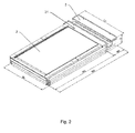
- FIG. 2 A system window set with an air outlet mounted beside the frame top member, with main dimensions marked, is shown in Fig. 2 .
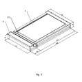
- FIG. 3 A system window set with an air outlet mounted beside the frame bottom member, with main dimensions marked, is shown in Fig. 3 .
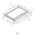
- FIG. 4 A system window set with an air outlet mounted beside one of the frame side members, with main dimensions marked, is shown in Fig. 4 .
- FIG. 5 A system window set with two air outlets mounted beside the frame top member, with main dimensions marked, is shown in Fig. 5 .
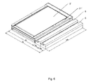
- FIG. 6 A system window set with two air outlets mounted beside one of the frame side members, with main dimensions marked, is shown in Fig. 6 .
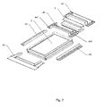
- a full flashing set for the window system according to the invention is shown as an exploded isometric drawing Fig. 7 ; Fig. 8 . shows a complete window with one air outlet, installed beside the frame top member of the window frame and the sheet metal flashing.
- the basic element of the system is constituted by a base window 1 shown in Fig. 1 with main dimensions marked, i.e. width Sb, height Wb and thickness G. These dimensions are a reference for other dimensions of the system.
- System windows and air outlets are complementary elements of the system. Depending on the installation place of the air outlet, basically three cases may be distinguished.
- the base window 1 is replaced by a system window 2 and the top air outlet 3.
- the top air outlet 3 is mounted beside the frame top member 21 of the system window 2.
- the total length Ln of the top air outlet 3 is equal to the width Ss of the system window 2 and, according to the proposed window system, equal to the width Sb of the base window 1, shown in Fig. 1 .
- Depths G of the top air outlet 3 and the system window 2 are preferably equal to the depth G of the base window 1.
- Height Wn of the top air outlet 3 is an element of the proposed window system and this dimension is a difference between the height Wb of the base window 1 and the height Ws of the system window 2.
- the system window 2 and the top air outlet 3 preferably have the size of the base window 1. Because of allowable working tolerances, a slight difference in sizes may occur, however it should remain in the limits of 5% of the individual dimensions, not more than several millimetres.
- the multi-element flashing set 4 shown in Fig. 7 and Fig. 8 being a complementary elements of the window system, sealing connection of the windows and the air outlets with the roof decking, consists of a top flashing 41, a bottom flashing 42, side channels 43 and a connector 44.
- the connector 44 is intended for sealing the connection of the system window 2 with the air outlet 3. Installation of elements of the flashing set 4 is realised in the sequence proper for the lap joint: the bottom flashing 42, the side channels 43, the connector 44 and the surmounting top flashing 41.
- the connector 44 has channel profiles 441 on both edges, for tight lap joining with the side channels 43 and, depending on its location, with the top flashing 41 or the bottom flashing 42.
- the flashing set 4 is used also for sealing the connection of the base window 1 with the roof decking.
- the connector 44 is an unnecessary element in this configuration.
- the side channels 43 joins as laps with the top flashing 41 and the bottom flashing 42, having the length sufficient to replace the channel profiles 441 belonging to the connector 44.
- the bottom air outlet 5 is mounted beside the frame bottom member 23 of the system window 2.
- the total length Ln of the bottom air outlet 5 is equal to the width Ss of the system window 2 and to the width Sb of the base window 1, shown in Fig. 1 .
- the depths G of the bottom air outlet 5 and the system window 2 are preferably equal to the depth G of the base window 1.
- Height Wn of the bottom air outlet 5 is an element of the proposed window system and this dimension is a difference between the height Wb of the base window 1 and the height Ws of the system window 2.
- the system window 2 and the top air outlet 3 preferably have the size of the base window 1.
- Other conditions are the same as those of the first case described above.
- the flashing set 4 shown in detail in the description of the first case may also be used in the second case, however the installation sequence of its individual elements requires swapping. Installation of elements of the flashing set 4 is realised in the sequence proper for the lap joint: the bottom flashing 42, the connector 44, the side channels 43 and the surmounting top flashing 41.
- the side air outlet 6 is mounted beside the frame side member 22. Its total length Ln is preferably equal to the height Wb of the base window 1 shown in Fig. 1 . Height Ws of the system window 2 is preferably equal to the height Wb of the base window 1. Depths G of the side air outlet 6 and the system window 2 are preferably equal to the depth G of the base window 1. Height Wn of the side air outlet 6 is an element of the proposed window system and this dimension is preferably a difference between the width Sb of the base window 1 and the width Ss of the system window 2.
- Fig. 5 For example, one of possible combinations, being a modification of the first case according to the invention, is shown in Fig. 5 . It comprises a system window 2', with height Ws, next lower one in the series of standard sizes in relation to the system window 2, and two top air outlets 3 mounted, one after the other, beside the frame top member 21'.
- a set meets the requirements of a window set according to the invention, meaning that the total height Ws of the system window and the heights Wn of two top air outlets 3 while assembled correspond basically to the height Wb of the base window.
- a similar arrangement may be assembled in the case of mounting of two side air outlets 6 beside one of the frame side members 22" of the system window 2". Assembly of the system window 2", with width Ss as next lower one in the series of standard sizes in relation to the system window 2 and two side air outlets 6 with the height Wn, yields the total width Sb of the base window 1.
Landscapes
- Engineering & Computer Science (AREA)
- Civil Engineering (AREA)
- Structural Engineering (AREA)
- Architecture (AREA)
- Roof Covering Using Slabs Or Stiff Sheets (AREA)
- Building Environments (AREA)
- Duct Arrangements (AREA)
- Specific Sealing Or Ventilating Devices For Doors And Windows (AREA)
Applications Claiming Priority (1)
| Application Number | Priority Date | Filing Date | Title |
|---|---|---|---|
| PL402644A PL232397B1 (pl) | 2013-02-04 | 2013-02-04 | System okienny z nawiewnikiem |
Publications (1)
| Publication Number | Publication Date |
|---|---|
| EP2762670A2 true EP2762670A2 (en) | 2014-08-06 |
Family
ID=50033368
Family Applications (1)
| Application Number | Title | Priority Date | Filing Date |
|---|---|---|---|
| EP20140153579 Withdrawn EP2762670A2 (en) | 2013-02-04 | 2014-02-03 | Window system with an air outlet |
Country Status (2)
| Country | Link |
|---|---|
| EP (1) | EP2762670A2 (pl) |
| PL (1) | PL232397B1 (pl) |
Cited By (3)
| Publication number | Priority date | Publication date | Assignee | Title |
|---|---|---|---|---|
| US11686096B2 (en) | 2019-12-30 | 2023-06-27 | Vkr Holding A/S | Roof window system with a ventilation unit mounted adjacent to the roof window, a roof structure including a roof window system, a method of providing a roof window system and a method of retrofitting a roof window system |
| US11834832B2 (en) | 2019-12-30 | 2023-12-05 | Vkr Holding A/S | Roof window system with a ventilation unit mounted adjacent to the roof window, and a method of providing ventilation for a building |
| EP4575129A1 (en) | 2023-12-21 | 2025-06-25 | VKR Holding A/S | Roof window with ventilation arrangement |
Citations (4)
| Publication number | Priority date | Publication date | Assignee | Title |
|---|---|---|---|---|
| WO2003001017A1 (en) | 2001-06-21 | 2003-01-03 | Vkr Holding A/S | Window with ventilating aperture |
| WO2005038165A1 (en) | 2003-10-21 | 2005-04-28 | Vkr Holding A/S | Tilting window |
| EP1656484B1 (en) | 2003-08-20 | 2006-12-06 | VKR Holding A/S | A window, a window system comprising a plurality of sizes, and a method of providing a window with a displaced hinge axis |
| WO2008133539A2 (en) | 2007-04-27 | 2008-11-06 | Fakro Pp Spolka Z O. O. | Roof window with air supply channel |
-
2013
- 2013-02-04 PL PL402644A patent/PL232397B1/pl unknown
-
2014
- 2014-02-03 EP EP20140153579 patent/EP2762670A2/en not_active Withdrawn
Patent Citations (4)
| Publication number | Priority date | Publication date | Assignee | Title |
|---|---|---|---|---|
| WO2003001017A1 (en) | 2001-06-21 | 2003-01-03 | Vkr Holding A/S | Window with ventilating aperture |
| EP1656484B1 (en) | 2003-08-20 | 2006-12-06 | VKR Holding A/S | A window, a window system comprising a plurality of sizes, and a method of providing a window with a displaced hinge axis |
| WO2005038165A1 (en) | 2003-10-21 | 2005-04-28 | Vkr Holding A/S | Tilting window |
| WO2008133539A2 (en) | 2007-04-27 | 2008-11-06 | Fakro Pp Spolka Z O. O. | Roof window with air supply channel |
Cited By (4)
| Publication number | Priority date | Publication date | Assignee | Title |
|---|---|---|---|---|
| US11686096B2 (en) | 2019-12-30 | 2023-06-27 | Vkr Holding A/S | Roof window system with a ventilation unit mounted adjacent to the roof window, a roof structure including a roof window system, a method of providing a roof window system and a method of retrofitting a roof window system |
| US11834832B2 (en) | 2019-12-30 | 2023-12-05 | Vkr Holding A/S | Roof window system with a ventilation unit mounted adjacent to the roof window, and a method of providing ventilation for a building |
| US11993934B2 (en) | 2019-12-30 | 2024-05-28 | Vkr Holding A/S | Roof window system with a ventilation unit mounted adjacent to the roof window, a roof structure including a roof window system, a method of providing a roof window system and a method of retrofitting a roof window system |
| EP4575129A1 (en) | 2023-12-21 | 2025-06-25 | VKR Holding A/S | Roof window with ventilation arrangement |
Also Published As
| Publication number | Publication date |
|---|---|
| PL232397B1 (pl) | 2019-06-28 |
| PL402644A1 (pl) | 2014-08-18 |
Similar Documents
| Publication | Publication Date | Title |
|---|---|---|
| EP2568094B1 (en) | A roof window, in particular a roof window apt to be mounted within a set of solar panels | |
| EP2762670A2 (en) | Window system with an air outlet | |
| EP3404162B1 (en) | A roof window installed in an inclined roof structure with a flashing assembly and a method for weather proofing a roof window | |
| EP2487307A2 (en) | Window set for barrel roof | |
| JP2019120022A (ja) | 二重サッシ | |
| EP2762653B2 (en) | Roof window set with an air outlet | |
| WO2009084878A3 (en) | Double window having horizontal cross-ventilation function | |
| CN104947861A (zh) | 预制舱透气防水结构 | |
| TWM529723U (zh) | 屋頂之通風構造 | |
| KR102794524B1 (ko) | 창호 체결 안전난간 장치 | |
| JP5833404B2 (ja) | 破風化粧板 | |
| JP6487199B2 (ja) | 化粧部材 | |
| EP3404161A1 (en) | A flashing assembly and a method for weather proofing a roof window mounted in an inclined roof surface | |
| WO2011120478A2 (en) | A door opening between rooms | |
| EP2048318B1 (en) | Assembly of a ventilation device and a rebate of a window | |
| EP2749725A2 (en) | Sash window and method of assembling thereof | |
| EP2432948B1 (en) | Modular sandwich panel and assembly method | |
| CN101415901B (zh) | 自身式百叶窗开口 | |
| EP3039200B1 (en) | A window adapted for being mounted in an inclined surface of a building and a method for water proofing such a window | |
| CN213983784U (zh) | 吊顶空调面板及吊顶空调系统 | |
| CN209369193U (zh) | 一种金属屋面板系统 | |
| EP3246486B1 (en) | Folding base | |
| JP7037783B2 (ja) | 軒天換気材 | |
| CN204830368U (zh) | 防水结构及通风器 | |
| JP4177832B2 (ja) | ガラリ用縦羽板及びガラリ |
Legal Events
| Date | Code | Title | Description |
|---|---|---|---|
| PUAI | Public reference made under article 153(3) epc to a published international application that has entered the european phase |
Free format text: ORIGINAL CODE: 0009012 |
|
| 17P | Request for examination filed |
Effective date: 20140211 |
|
| AK | Designated contracting states |
Kind code of ref document: A2 Designated state(s): AL AT BE BG CH CY CZ DE DK EE ES FI FR GB GR HR HU IE IS IT LI LT LU LV MC MK MT NL NO PL PT RO RS SE SI SK SM TR |
|
| AX | Request for extension of the european patent |
Extension state: BA ME |
|
| STAA | Information on the status of an ep patent application or granted ep patent |
Free format text: STATUS: THE APPLICATION HAS BEEN WITHDRAWN |
|
| 18W | Application withdrawn |
Effective date: 20160118 |