EP3246486B1 - Folding base - Google Patents
Folding base Download PDFInfo
- Publication number
- EP3246486B1 EP3246486B1 EP16001120.1A EP16001120A EP3246486B1 EP 3246486 B1 EP3246486 B1 EP 3246486B1 EP 16001120 A EP16001120 A EP 16001120A EP 3246486 B1 EP3246486 B1 EP 3246486B1
- Authority
- EP
- European Patent Office
- Prior art keywords
- base
- projections
- side wall
- side walls
- edge
- Prior art date
- Legal status (The legal status is an assumption and is not a legal conclusion. Google has not performed a legal analysis and makes no representation as to the accuracy of the status listed.)
- Active
Links
- 238000005452 bending Methods 0.000 claims description 9
- 238000009423 ventilation Methods 0.000 claims description 8
- 230000001154 acute effect Effects 0.000 claims description 3
- 239000000779 smoke Substances 0.000 description 11
- 230000000694 effects Effects 0.000 description 3
- 238000009434 installation Methods 0.000 description 3
- 238000010276 construction Methods 0.000 description 2
- 229910052751 metal Inorganic materials 0.000 description 2
- 239000002184 metal Substances 0.000 description 2
- 238000000034 method Methods 0.000 description 2
- 241000826860 Trapezium Species 0.000 description 1
- 238000004378 air conditioning Methods 0.000 description 1
- 239000004411 aluminium Substances 0.000 description 1
- 229910052782 aluminium Inorganic materials 0.000 description 1
- XAGFODPZIPBFFR-UHFFFAOYSA-N aluminium Chemical compound [Al] XAGFODPZIPBFFR-UHFFFAOYSA-N 0.000 description 1
- 230000015572 biosynthetic process Effects 0.000 description 1
- 230000008030 elimination Effects 0.000 description 1
- 238000003379 elimination reaction Methods 0.000 description 1
- 239000011152 fibreglass Substances 0.000 description 1
- 238000009413 insulation Methods 0.000 description 1
- 230000003993 interaction Effects 0.000 description 1
- 239000000463 material Substances 0.000 description 1
- 239000011490 mineral wool Substances 0.000 description 1
- 239000004033 plastic Substances 0.000 description 1
- 238000011282 treatment Methods 0.000 description 1
- XLYOFNOQVPJJNP-UHFFFAOYSA-N water Substances O XLYOFNOQVPJJNP-UHFFFAOYSA-N 0.000 description 1
Images


Classifications
-
- E—FIXED CONSTRUCTIONS
- E04—BUILDING
- E04D—ROOF COVERINGS; SKY-LIGHTS; GUTTERS; ROOF-WORKING TOOLS
- E04D13/00—Special arrangements or devices in connection with roof coverings; Protection against birds; Roof drainage; Sky-lights
- E04D13/03—Sky-lights; Domes; Ventilating sky-lights
- E04D13/0305—Supports or connecting means for sky-lights of flat or domed shape
- E04D13/0315—Supports or connecting means for sky-lights of flat or domed shape characterised by a curb frame
Definitions
- the invention relates to a folding base for a roof unit, intended to be installed on the roof of a building to mount a roof unit on it, especially a roof hatch, a skylight or a smoke damper.
- the base is fixed on edges of an opening in the roof of a building, and when fixed said base is an upstand to which a roof unit is attached.
- the base for smoke vents and skylights comprises a body made of aluminium sheets, having in a cross-section the shape of a trapezium with a bigger base, arranged in the lower base plane, comprising a bottom external fixing plate.
- the body comprises on a smaller, upper base a shaped horizontal retaining plate in the form of a flat rigid flange.
- On the flange an upper covering frame is mounted, in an interference fit, made of a plastic profile.
- an insulating layer in the form of mineral wool is permanently fixedly applied.
- Polish patent specification No. PL 202876 Another known solution is disclosed in Polish patent specification No. PL 202876 .
- This solution relates to an insulating frame comprising upper, bottom and side members which, in principle, are made of a material with good insulation properties, and a roof window in an installation position is adjusted to adhere with its frame to the insulating frame.
- the frame is made up of separate frame members and each member of the frame has such a cross-section that the frame on at least a substantial portion of its height comprises a light transmitting opening which is bigger than the outer dimensions of the frame.
- the frame is provided with fixing means for fixing said frame on a roof structure and/or a roof window.
- Polish patent specification No. PL 217605 Another known solution is disclosed in Polish patent specification No. PL 217605 .
- This solution relates to a roof base intended to be installed on the roof of a building for mounting various kinds of ventilation units thereon, in particular fans.
- a rectangular flange is tiltably fixed in relation to a cuboidal ventilation pipe.
- the size of a rectangular through opening in the rectangular flange, used to mount the cuboidal ventilation pipe thereon is variable, depending on the angle of inclination of the rectangular flange in relation to the cuboidal ventilation pipe.
- Polish utility model application No. W.114256 Another known solution is disclosed in Polish utility model application No. W.114256 .
- the model relates to a roof flange comprising a hollow pass-through base inside connected to a fixing skirt and a cap, covering the base, with a vent pipe sleeve clamp.
- the base and the cap have flat side walls matched to one another and front walls arched in a cross-section.
- the front walls of the base have different lengths and different inclinations in relation to the bottom plane of the base, and the front walls of the cap- different lengths.
- the front walls of the base are rectilinear along their length within interaction with the cap, and the front walls of the cap are curved along their length to create a convex arc.
- a mounting flange comprising substantially flat U-shaped film members with a bending, on the sides of which flange portions are arranged for fixing the mounting flange to the mutually connected outer sides of the main frame structure of a window or a roof installation so that the film portion extends substantially parallel to the roof surface in order to connect it with adjacent parts of an attic.
- the mounting flange can be made in a simple way so that transverse seals are made on two overlapping film strips in distances corresponding to a predetermined width of the frame.
- each seal with two parallel-sealed sections is formed, and in edge zones, on opposite sides of the film strip in the extension of the one and the other, respectively, from two parallel-sealed sections, sealed sections are formed which are perpendicular to side edges.
- the flange members are then separated by cutting along the lines of cuts between the parallelly combined sections and in parallel to the sealed sections perpendicular to the side edges, and the structure of the flange is ended by cutting one film strip along a central line between the sealed sections with the occurring upward bending of the fixing flange portions.
- European patent application No. EP 2351893 discloses a rectangular shaped base comprising a top base element and a bottom element.
- the base is a kind of an upstand with a central through opening between four slanting side walls on a rectangular plan and is based on the edges of a roof opening.
- An upper rim of the base is intended for mounting a window or a roof hatch thereon.
- the base is a folding structure.
- Each of the four substantially vertical corner angles comprises two hooks near each of the vertical edges.
- the four base walls are mounted on the hooks of the corner angles, and then the whole is topped by the upper rim which stabilises the folded base.
- EP 0967345 discloses another solution of a base for skylights, ventilation system units and any roof units.
- the base is preferably made of fibreglass with the aim to avoid the stagnation of rain water around a skylight. Said base creates a continuous surface of the insulating cover.
- US 5687514 discloses another solution of a curb for encasing openings for units mounted on a roof.
- the curb has a rectangular box structure, delimited by four side walls. Each side wall in an upper part is bent outwards forming on the upper edge of the curb a flange to which an external unit in the form of a smoke vent window and other roof units can be mounted.
- the connected side walls using pre-drilled holes are mounted on a bottom flange.
- the curb is folding and is connected by means of screws using corner angles.
- a base comprises side walls each having integral fixing elements for fixing a neighboring side wall.
- the side walls are made from bendable sheet metal.
- the side walls have slots on the edge side into which a protruding clip from a neighboring side wall is inserted.
- Each side wall has a base flange with angled wall sections and an upper edge section.
- the invention solves the problem of reducing the dimensions of a base during its transport.
- the dimensions of a base before it is assembled in the place of destination result in a need for a certain space in means of transport to deliver a base to a construction site, where the internal space of a base is an empty space to a large extent.
- the solution to this problem is the development of a folding base of flat parts which do not contain empty spaces.
- a base is assembled by connecting previously prepared parts using screws, which is labour-intensive, especially in the case of roofs of industrial or commercial facilities with a huge number of such roof units.
- individual parts are assembled by putting hooks of some parts into slots formed in other parts.
- the purpose of the invention is to develop a base structure for roof units, in particular such units as roof hatches, skylights, smoke vents and ventilation flaps, as a folding base, which is easy and quick to assemble, and at the same time characterised by a rigid structure, without clearance in connections of individual parts and enabling quick and easy elimination of clearance, if any.
- This task has been solved by the development of the folding base structure according to claim 1 and the subsequent claims.
- the folding base in particular for window roof units and ventilation and fire protection units has the form of side walls and connecting members.
- Each side wall comprises an upper and bottom edge and two side edges with connecting members.
- the side walls comprise portions of a bottom flange fixing the base to the roof and portions of an upper flange to which a roof unit is attached.
- the folding base according to the invention is characterised by the features of claim 1, in particular in that the side edges of the adjacent side walls comprise rows of projections.
- Each projection has the form of a flat being an extension of the surface of the side wall.
- Each projection is bent along a line parallel to the edge of the side wall at an acute angle outwards of the base.
- the projections described above with a comb-like arrangement on each side edge of the base side wall are separated from one another by spaces.
- a row of comb-like projections on one side edge of the side wall is moved in relation to a row of comb-like projections on another side edge of the side wall, so that after putting two perpendicular side walls together, in the areas of spaces on the edge of one side wall in the assembled base the comb-like arranged projections of another side wall are arranged.
- the side edge of the side wall should be understood as a common line determined by the spaces between the comb-like arranged projections.
- bent sections of the projections of two combined at a right angle, adjacent side walls of the base, in a view consistent with the direction of the connection edge of the two walls preferably form a semi-enclosed section.
- the projections are preferably bent along the lines parallel to the side edges determined by the projections on the side edge of the side wall.
- the semi-enclosed section preferably has the shape of a triangle, and the pin has the form of an angle whose arms correspond to the length of the arms of the triangle of the semi-enclosed section.
- the base is proposed for roof units, such as windows, smoke vents, air vents and smoke vent flaps, assembled of side walls which contain on edges a system of comb-like connecting projections.
- roof units such as windows, smoke vents, air vents and smoke vent flaps
- the comb-like projections of one side wall enter into spaces between the same projections of the adjacent perpendicular side wall.
- the comb-like projections are formed so that the meshed projections of adjacent walls form a fully rigid vertical connection, very easy to be assembled on the roof.
- the vertical rigidity in this solution is achieved by inserting a connecting member in the form a pin into a chamber formed by the projections of one side wall alternately arranged one under the other and the projections of the adjacent side wall.
- the shape of the connecting pin is matched to the shape of the internal chamber which is created in a view corresponding to the direction of the chamber by the bent projections put between one another of two adjacent side walls.
- a connection is achieved by simple inserting the connecting pin, which is a very simple activity to perform during the assembly process of such a base.
- the solution according to the invention has proved to be particularly advantageous in work performed on the roof. When all the side walls are connected, the final rigidity of the base structure is obtained by fixing parts of the bottom flange to the roof surface. Since usually a lot of this kind of bases for roof units are installed on large industrial or commercial facilities, the issues of transport of often a huge number of bases to a construction site are important.
- the solution according to the invention has greatly enabled the reduction of the volume of the flat base according to the invention, before assembly on the roof, in transport operations.
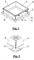
- FIG. 1 , Fig. 6 and Fig. 8 show one embodiment of the base according to the invention comprising four side walls on a square plan.
- the base comprises the side walls 1,2,3,4, a bottom flange 5 and an upper flange 6.
- the flanges 5,6 can be shaped as parts of the side walls 1,2,3,4 and connected at corners by means of corner connectors 7.
- Each side wall 1,2,3,4 comprises an upper and bottom edge and two side edges with connecting members. As shown in the figures in this embodiment, the side walls 1,2,3,4 are connected by the side edges and form a square. In other embodiments they can form a rectangle or other flat geometrical figure.
- Fig. 1 shows fixed to the upper flange 6 hinges 14 to which, for example, a smoke vent can be fixed, as shown in Fig. 8 .
- This type of a vent or a roof window is usually fitted with a mechanism for remote closing and opening, which is, however, not shown here, because it is not the subject of the invention.
- Fig. 2 , Fig. 3 and Fig. 4 show that the side edges of the adjacent side walls 1,2 comprise rows of projections.
- the side wall 1 comprises the projections 8 and the side wall 2 also comprises the projections 8.
- Fig. 3 and Fig. 4 show only parts of the edges of the side walls 1,2 in an enlarged view.
- Fig. 1 and Fig. 2 show that each side edge of the side wall 1,2 comprises three projections 8. In other embodiments the number of projections on the edges of the side walls can be different.
- each projection 8 has the form of a flat being an extension of the surface of the side wall 1,2,3,4.
- Each projection 8 is bent along a bending line 9 parallel to the edge of the side wall 1,2,3,4 at an acute angle outwards of the base.
- the term outwards of the base should be understood in this patent specification so that the end portion of the projection 8 is bent from the inside of the base to the outside.
- the comb-like arranged, one in a certain distance from the other, projections 8 on each side edge of the side wall 1,2,3,4 of the base are separated from one another by spaces 10.
- a row of the comb-like projections 8 on one side edge of the side wall 1 is moved in relation to a row of the comb-like projections 8 on another side edge of the side wall 1.
- the comb-like arranged projections 8 of another side wall 2 of the base are arranged.
- the side edge of the side wall 1,2,3,4 should be understood as a common line determined by the spaces 10 between the comb-like arranged projections 8.
- Each of the side walls 1,2,3,4 of the base according to the invention has the same arrangement of the comb-like projections 8 but moved on one side edge in relation to the other side edge of the side wall 1,2,3,4.
- the comb-like arranged projections 8 of one side wall take the place of the comb-like arranged projections 8 of the other side wall.
- the projections 8 are preferably bent along the bending lines 9 parallel to the side edges determined by the projections 10 on the side edges of the walls 1,2,3,4.
- Fig. 5 shows that the projections 8 of the wall 1 are bent along the bending edge 9 at an angle of 45°. This figure schematically shows stiffening embossments of the side wall 1 in this embodiment.
- FIG. 7 An example of a connection of the side walls 1,2 prepared in this way is shown in Fig. 7 in a view consistent with the direction of the resulting connection.
- the projections 8 of the side walls 1,2 constitute in a top view an internal chamber in the form of a semi-enclosed section 11 in the form of a triangle.
- the semi-enclosed section 11 has the shape of an equilateral triangle.
- a connector in the form of a pin 12 is inserted into the semi-enclosed section 11.
- the same pin 12 is shown in Fig. 4 before being inserted between the projections 8 of the adjacent walls 1,2.
- the pin 12 has the length corresponding to the height of connections of the side walls 1,2,3,4.
- the pin 12 has the form of an angle with an angle of 90°, whose width of arms corresponds to the length of the catheti of said triangle of the semi-enclosed section 11.
- the particular projections 8 may be individually subjected to the pressure of the pin 12 which contributes to the resulting rigidity of the edge of each connection of two perpendicular side walls of the base. Where some of the projections 8 protrude from the pin 12, these projections can be simply struck with a hammer to the pin 12, which in working conditions on the roof is not a complicated activity.
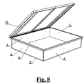
- Fig. 8 shows the assembled base according to the invention with a smoke vent 13 which is in this figure an example of a roof unit mounted on the base according to the invention.
Description
- The invention relates to a folding base for a roof unit, intended to be installed on the roof of a building to mount a roof unit on it, especially a roof hatch, a skylight or a smoke damper.
- The base is fixed on edges of an opening in the roof of a building, and when fixed said base is an upstand to which a roof unit is attached.
- There is a number of solutions of bases for fixing this type of roof units. A known solution is disclosed in Polish patent application No.
P 315827 - Another known solution is disclosed in Polish patent specification No.
PL 202876 - Another known solution is disclosed in Polish patent specification No.
PL 217605 - Another known solution is disclosed in Polish utility model application No.
W.114256 - Another solution is also known disclosed in the publication of the invention applied under the international procedure No.
WO 94/08108 - European patent application No.
EP 2351893 discloses a rectangular shaped base comprising a top base element and a bottom element. The base is a kind of an upstand with a central through opening between four slanting side walls on a rectangular plan and is based on the edges of a roof opening. An upper rim of the base is intended for mounting a window or a roof hatch thereon. According to this known solution the base is a folding structure. Each of the four substantially vertical corner angles comprises two hooks near each of the vertical edges. On each two corner angles, on said hooks a side wall is mounted, which in appropriate places comprises slots for fixing the side wall on the hooks of the corner angles. In this way the four base walls are mounted on the hooks of the corner angles, and then the whole is topped by the upper rim which stabilises the folded base. - Another European patent application No.
EP 0967345 discloses another solution of a base for skylights, ventilation system units and any roof units. The base is preferably made of fibreglass with the aim to avoid the stagnation of rain water around a skylight. Said base creates a continuous surface of the insulating cover. - Another solution known from US patent specification No.
US 5687514 discloses another solution of a curb for encasing openings for units mounted on a roof. The curb has a rectangular box structure, delimited by four side walls. Each side wall in an upper part is bent outwards forming on the upper edge of the curb a flange to which an external unit in the form of a smoke vent window and other roof units can be mounted. The connected side walls using pre-drilled holes are mounted on a bottom flange. In this known solution, the curb is folding and is connected by means of screws using corner angles. - According to utility model description
DE 20 2006 000881 , a base comprises side walls each having integral fixing elements for fixing a neighboring side wall. The side walls are made from bendable sheet metal. The side walls have slots on the edge side into which a protruding clip from a neighboring side wall is inserted. Each side wall has a base flange with angled wall sections and an upper edge section. - According to patent description
US 6041557 the four metal panel portions of an air conditioning unit roof curb have spaced sets of inwardly projecting lanced portions positioned adjacent their ends and defining tab-receiving slots. With the panel portions in a rectangular assembly orientation, specially designed drive cleats are used to lock the contiguous ends of the panel portions together at the corners of the curb. - Other bases for roof units are known from
US 5148647 andUS 3802131 . - The invention solves the problem of reducing the dimensions of a base during its transport. The dimensions of a base before it is assembled in the place of destination result in a need for a certain space in means of transport to deliver a base to a construction site, where the internal space of a base is an empty space to a large extent. The solution to this problem is the development of a folding base of flat parts which do not contain empty spaces. In prior art solutions a base is assembled by connecting previously prepared parts using screws, which is labour-intensive, especially in the case of roofs of industrial or commercial facilities with a huge number of such roof units. However, in other known solutions of a folding base, individual parts are assembled by putting hooks of some parts into slots formed in other parts. This type of connections using hooks in slots are characterised by certain clearance in these connections, because making a slot in one part with exactly the same width as the thickness of an interacting hook will make it impossible to put such a hook into this slot. To make this possible, it is necessary to design a slot which is slightly wider than the thickness of a hook. However, after putting a hook into such a slot, there is a certain degree of clearance in such a connection. As a result of wind gusts from different directions this natural clearance in connections of parts of a base, in particular in roof units, can be greater over time. These effects can be eliminated but this requires additional treatments.
- The purpose of the invention is to develop a base structure for roof units, in particular such units as roof hatches, skylights, smoke vents and ventilation flaps, as a folding base, which is easy and quick to assemble, and at the same time characterised by a rigid structure, without clearance in connections of individual parts and enabling quick and easy elimination of clearance, if any. This task has been solved by the development of the folding base structure according to
claim 1 and the subsequent claims. - According to the invention, the folding base, in particular for window roof units and ventilation and fire protection units has the form of side walls and connecting members. Each side wall comprises an upper and bottom edge and two side edges with connecting members. The side walls comprise portions of a bottom flange fixing the base to the roof and portions of an upper flange to which a roof unit is attached.
- The folding base according to the invention is characterised by the features of
claim 1, in particular in that the side edges of the adjacent side walls comprise rows of projections. Each projection has the form of a flat being an extension of the surface of the side wall. Each projection is bent along a line parallel to the edge of the side wall at an acute angle outwards of the base. The projections described above with a comb-like arrangement on each side edge of the base side wall are separated from one another by spaces. A row of comb-like projections on one side edge of the side wall is moved in relation to a row of comb-like projections on another side edge of the side wall, so that after putting two perpendicular side walls together, in the areas of spaces on the edge of one side wall in the assembled base the comb-like arranged projections of another side wall are arranged. In this patent specification, the side edge of the side wall should be understood as a common line determined by the spaces between the comb-like arranged projections. - The bent sections of the projections of two combined at a right angle, adjacent side walls of the base, in a view consistent with the direction of the connection edge of the two walls preferably form a semi-enclosed section.
- The projections are preferably bent along the lines parallel to the side edges determined by the projections on the side edge of the side wall.
- Inside the semi-enclosed section between the bent projections along the entire length of contact of the side edges of two side walls, there is an inserted pin, parallel to the contact, with a section corresponding to the form of the semi-enclosed section.
- The semi-enclosed section preferably has the shape of a triangle, and the pin has the form of an angle whose arms correspond to the length of the arms of the triangle of the semi-enclosed section.
- According to the invention, the base is proposed for roof units, such as windows, smoke vents, air vents and smoke vent flaps, assembled of side walls which contain on edges a system of comb-like connecting projections. In two side edges of adjacent side walls, the comb-like projections of one side wall enter into spaces between the same projections of the adjacent perpendicular side wall. The comb-like projections are formed so that the meshed projections of adjacent walls form a fully rigid vertical connection, very easy to be assembled on the roof. The vertical rigidity in this solution is achieved by inserting a connecting member in the form a pin into a chamber formed by the projections of one side wall alternately arranged one under the other and the projections of the adjacent side wall. The shape of the connecting pin is matched to the shape of the internal chamber which is created in a view corresponding to the direction of the chamber by the bent projections put between one another of two adjacent side walls. A connection is achieved by simple inserting the connecting pin, which is a very simple activity to perform during the assembly process of such a base. The solution according to the invention has proved to be particularly advantageous in work performed on the roof. When all the side walls are connected, the final rigidity of the base structure is obtained by fixing parts of the bottom flange to the roof surface. Since usually a lot of this kind of bases for roof units are installed on large industrial or commercial facilities, the issues of transport of often a huge number of bases to a construction site are important. The solution according to the invention has greatly enabled the reduction of the volume of the flat base according to the invention, before assembly on the roof, in transport operations.
- The subject of the invention is shown in the embodiment in the accompanying drawing in which the individual figures show:
- Fig. 1 -
- the view of the assembled base.
- Fig. 2 -
- the view of a connection detail of
Fig. 1 . - Fig. 3 -
- the view of edges of side walls before connecting the edges.
- Fig. 4 -
- the view of the edges according to
Fig. 3 after moving the edges of side walls towards each other. - Fig. 5 -
- the view of the projection's bending profile.
- Fig. 6 -
- the top view of the assembled base.
- Fig. 7 -
- a connection detail of
Fig. 6 . - Fig. 8 -
- the assembled base with the smoke vent.
- The accompanying
Fig. 1 ,Fig. 6 andFig. 8 show one embodiment of the base according to the invention comprising four side walls on a square plan. The base comprises theside walls bottom flange 5 and an upper flange 6. Theflanges 5,6 can be shaped as parts of theside walls corner connectors 7. - Each
side wall side walls Fig. 1 shows fixed to the upper flange 6 hinges 14 to which, for example, a smoke vent can be fixed, as shown inFig. 8 . This type of a vent or a roof window is usually fitted with a mechanism for remote closing and opening, which is, however, not shown here, because it is not the subject of the invention. -
Fig. 2 ,Fig. 3 and Fig. 4 show that the side edges of theadjacent side walls side wall 1 comprises theprojections 8 and theside wall 2 also comprises theprojections 8.Fig. 3 and Fig. 4 show only parts of the edges of theside walls Fig. 1 and Fig. 2 show that each side edge of theside wall projections 8. In other embodiments the number of projections on the edges of the side walls can be different. -
Fig. 3 and Fig. 4 show that eachprojection 8 has the form of a flat being an extension of the surface of theside wall projection 8 is bent along abending line 9 parallel to the edge of theside wall projection 8 is bent from the inside of the base to the outside. - The comb-like arranged, one in a certain distance from the other,
projections 8 on each side edge of theside wall spaces 10. A row of the comb-like projections 8 on one side edge of theside wall 1 is moved in relation to a row of the comb-like projections 8 on another side edge of theside wall 1. In the areas of thespaces 10 on the edge of oneside wall 1 in the assembled base the comb-like arrangedprojections 8 of anotherside wall 2 of the base are arranged. In this patent specification, the side edge of theside wall spaces 10 between the comb-like arrangedprojections 8. Each of theside walls like projections 8 but moved on one side edge in relation to the other side edge of theside wall side walls projections 8 of one side wall take the place of the comb-like arrangedprojections 8 of the other side wall. Theprojections 8 are preferably bent along thebending lines 9 parallel to the side edges determined by theprojections 10 on the side edges of thewalls Fig. 5 shows that theprojections 8 of thewall 1 are bent along the bendingedge 9 at an angle of 45°. This figure schematically shows stiffening embossments of theside wall 1 in this embodiment. - An example of a connection of the
side walls Fig. 7 in a view consistent with the direction of the resulting connection. As it is shown in this figure, theprojections 8 of theside walls semi-enclosed section 11 in the form of a triangle. In a view as inFig. 7 , the section seems to be closed. Thesemi-enclosed section 11 has the shape of an equilateral triangle. A connector in the form of apin 12 is inserted into thesemi-enclosed section 11. Thesame pin 12 is shown inFig. 4 before being inserted between theprojections 8 of theadjacent walls pin 12 has the length corresponding to the height of connections of theside walls pin 12 has the form of an angle with an angle of 90°, whose width of arms corresponds to the length of the catheti of said triangle of thesemi-enclosed section 11. When thepin 12 is inserted, theparticular projections 8 may be individually subjected to the pressure of thepin 12 which contributes to the resulting rigidity of the edge of each connection of two perpendicular side walls of the base. Where some of theprojections 8 protrude from thepin 12, these projections can be simply struck with a hammer to thepin 12, which in working conditions on the roof is not a complicated activity. -
Fig. 8 shows the assembled base according to the invention with asmoke vent 13 which is in this figure an example of a roof unit mounted on the base according to the invention. -
- 1. Side wall.
- 2. Side wall.
- 3. Side wall.
- 4. Side wall.
- 5. Bottom flange.
- 6. Upper flange.
- 7. Corner connector.
- 8. Projection.
- 9. Bending edge.
- 10.Space.
- 11.Semi-enclosed section.
- 12.Pin.
- 13. Smoke vent.
- 14.Hinge.
Claims (4)
- A folding base for roof units in particular for window roof units or for ventilation or fire protection roof units, comprising side walls (1,2,3,4) and connecting members,- where each side wall (1,2,3,4) comprises an upper and bottom edge and two side edges, and at least one connecting member connecting two adjacent side walls (1,2,3,4) together,- where the side walls (1,2,3,4) comprise portions of a bottom flange (5) fixing the base to the roof and portions of an upper flange (6) to which a roof unit is attached,- wherein the connecting members of the adjacent side walls (1,2,3,4) comprise rows of comb-like arranged projections (8) on side edges of the side walls (1,2,3,4),- where each projection (8) is made of a flat element being an extension of the surface of the side wall (1,2,3,4),- where each projection (8) is bent along a bending edge (9) parallel to the side edge of the side wall (1,2,3,4),- and the comb-like arranged projections (8) on each side edge of the side walls (1,2,3,4) of the base are separated from one another by spaces (10),- where during assembly a row of the comb-like projections (8) on one side edge of each side wall (1,2,3,4) is moveable in relation to a row of the comb-like projections (8) on another side edge of another side wall (1,2,3,4), so that in the assembled base, in the areas of the spaces (10) between the comb-like projections (8) on the edge of one side wall (1,2,3,4), the comb-like projections (8) of the adjacent side wall (1,2,3,4) of the base are arrangedcharacterised in that,
each projection (8) is bent along a bending edge (9) parallel to the side wall (1,2,3,4) at an acute angle outwards of the base. - The folding base, according to claim 1, characterised in that the bent sections of the projections (8) of two combined adjacent side walls (1,2,3,4) of the base in a view consistent with the direction of the connection edge of the two side walls (1,2,3,4) form a semi-enclosed section (11).
- The folding base, according to claim 2, characterised in that inside the semi-enclosed section (11) between the bent projections (8) along the entire length of contact of the side edges of two adjacent side walls (1,2,3,4) there is an inserted connecting member in the form of a pin (12) of the shape of a section corresponding to the shape of the semi-enclosed section (11).
- The folding base, according to claim 2 or 3, characterised in that the semi-enclosed section (11) is a triangle, and the pin (12) has the form of an angle whose width of arms corresponds to the length of two arms of the triangle of the semi-enclosed section (11).
Priority Applications (2)
| Application Number | Priority Date | Filing Date | Title |
|---|---|---|---|
| PL16001120T PL3246486T3 (en) | 2016-05-17 | 2016-05-17 | Folding base |
| EP16001120.1A EP3246486B1 (en) | 2016-05-17 | 2016-05-17 | Folding base |
Applications Claiming Priority (1)
| Application Number | Priority Date | Filing Date | Title |
|---|---|---|---|
| EP16001120.1A EP3246486B1 (en) | 2016-05-17 | 2016-05-17 | Folding base |
Publications (2)
| Publication Number | Publication Date |
|---|---|
| EP3246486A1 EP3246486A1 (en) | 2017-11-22 |
| EP3246486B1 true EP3246486B1 (en) | 2018-12-12 |
Family
ID=56119265
Family Applications (1)
| Application Number | Title | Priority Date | Filing Date |
|---|---|---|---|
| EP16001120.1A Active EP3246486B1 (en) | 2016-05-17 | 2016-05-17 | Folding base |
Country Status (2)
| Country | Link |
|---|---|
| EP (1) | EP3246486B1 (en) |
| PL (1) | PL3246486T3 (en) |
Family Cites Families (14)
| Publication number | Priority date | Publication date | Assignee | Title |
|---|---|---|---|---|
| DE1861685U (en) * | 1962-08-04 | 1962-11-08 | Dynamit Nobel Ag | UPPER CROWN FOR LIGHT DOME. |
| US3802131A (en) * | 1972-04-24 | 1974-04-09 | Pate Mfg Co | Flashing base with adjustable cant |
| HU175059B (en) | 1976-12-13 | 1980-05-28 | Budapesti Adiotechnikai Gyar | Circuit arrangement for controlling high-power d.c. sources |
| PL117870B2 (en) | 1979-08-07 | 1981-08-31 | Polskie Koleje Panstwowe | Bidirectional automatic line blocking system in particular for long station-to-station distanceskirovki,a osobenno dlja mezhstancionnogo rasstojanija bolshojj protjazhennosti |
| US4781008A (en) * | 1986-07-11 | 1988-11-01 | The Bilco Company | Frane assembly for building opening |
| US5148647A (en) * | 1991-08-16 | 1992-09-22 | Rooftop Systems Inc. | Roof mounting curb |
| DK123292A (en) | 1992-10-07 | 1994-04-08 | Rasmussen Kann Ind As | Connecting collar for sealingly connecting a ceiling to a skylight or other roof mounting element and method of manufacturing it |
| US5687514A (en) | 1996-01-03 | 1997-11-18 | Gillispie; John Joseph | Adjustable curb with flashing |
| PL315827A1 (en) | 1996-08-23 | 1998-03-02 | Zenon Malkowski | Base for roof ventilators and skylights |
| IT1305943B1 (en) | 1998-06-24 | 2001-05-21 | I C M P Snc Di De Benedictis G | BASE FOR SKYLIGHTS, SMOKE AND HEAT EXHAUSTS AND FOR ANY DISCONTINUITY PRESENT IN THE PITCH COVERINGS. |
| US6041557A (en) * | 1998-10-07 | 2000-03-28 | Rheem Manufacturing Company | Quick assembly roof curb apparatus |
| PL114256U1 (en) | 2003-08-04 | 2004-01-26 | Tadeusz Kaczmarczyk | Roof flashing |
| DE202006000881U1 (en) * | 2006-01-13 | 2006-04-13 | Essmann Gmbh | Cap for a dome light for flat roofs comprises side walls each having integral fixing elements for fixing a neighboring side wall |
| DE102010004224A1 (en) | 2010-01-08 | 2011-07-14 | E.M.B. Products AG, 89129 | Attachment base, in particular for roof openings, e.g. for smoke and heat exhaust systems |
-
2016
- 2016-05-17 EP EP16001120.1A patent/EP3246486B1/en active Active
- 2016-05-17 PL PL16001120T patent/PL3246486T3/en unknown
Non-Patent Citations (1)
| Title |
|---|
| None * |
Also Published As
| Publication number | Publication date |
|---|---|
| EP3246486A1 (en) | 2017-11-22 |
| PL3246486T3 (en) | 2019-06-28 |
Similar Documents
| Publication | Publication Date | Title |
|---|---|---|
| US5149301A (en) | Baffle means for roof ridge ventilator | |
| EP1715261A1 (en) | Solar energy collecting modular element for enclosure, and modular system for forming solar energy collecting enclosures on buildings | |
| US20130283725A1 (en) | Curbless multiple skylight and smoke vent system | |
| JP6205197B2 (en) | Building ventilation structure | |
| JP5128877B2 (en) | Opening device | |
| US4884379A (en) | Skylight structure and method of manufacture therefor | |
| KR101017573B1 (en) | Louver unit of ventilation window | |
| EP3246486B1 (en) | Folding base | |
| JP3159271U (en) | Ventilation building | |
| EP1870555B1 (en) | Ventilation unit | |
| JP6487199B2 (en) | Decorative material | |
| EP2487307A2 (en) | Window set for barrel roof | |
| US2988183A (en) | Mullion arrangement | |
| JP6862226B2 (en) | curtain wall | |
| EP3404162A1 (en) | A roof window installed in an inclined roof structure with a flashing assembly and a method for weather proofing a roof window | |
| JP5297563B1 (en) | Keraba decorative member and attachment method thereof | |
| JP4759644B1 (en) | Ventilation building | |
| JP5097033B2 (en) | Single-flow roof building ventilation structure | |
| CN108005558A (en) | The movable plank house of window belt sealing | |
| EP3061885B1 (en) | Window including a climate-shielding transition assembly | |
| ES2290669T3 (en) | COVER FOR A SURFACE OF BALCONIES, FLOORS, ROOFS OR FACADES. | |
| EP3404161B1 (en) | A flashing assembly and a method for weather proofing a roof window mounted in an inclined roof surface | |
| EP3795771B1 (en) | Skylight window | |
| JP5457862B2 (en) | Venting material and exterior wall structure of buildings | |
| JP5993118B2 (en) | Exterior wall structure |
Legal Events
| Date | Code | Title | Description |
|---|---|---|---|
| PUAI | Public reference made under article 153(3) epc to a published international application that has entered the european phase |
Free format text: ORIGINAL CODE: 0009012 |
|
| STAA | Information on the status of an ep patent application or granted ep patent |
Free format text: STATUS: THE APPLICATION HAS BEEN PUBLISHED |
|
| AK | Designated contracting states |
Kind code of ref document: A1 Designated state(s): AL AT BE BG CH CY CZ DE DK EE ES FI FR GB GR HR HU IE IS IT LI LT LU LV MC MK MT NL NO PL PT RO RS SE SI SK SM TR |
|
| AX | Request for extension of the european patent |
Extension state: BA ME |
|
| STAA | Information on the status of an ep patent application or granted ep patent |
Free format text: STATUS: REQUEST FOR EXAMINATION WAS MADE |
|
| 17P | Request for examination filed |
Effective date: 20180306 |
|
| RBV | Designated contracting states (corrected) |
Designated state(s): AL AT BE BG CH CY CZ DE DK EE ES FI FR GB GR HR HU IE IS IT LI LT LU LV MC MK MT NL NO PL PT RO RS SE SI SK SM TR |
|
| GRAP | Despatch of communication of intention to grant a patent |
Free format text: ORIGINAL CODE: EPIDOSNIGR1 |
|
| STAA | Information on the status of an ep patent application or granted ep patent |
Free format text: STATUS: GRANT OF PATENT IS INTENDED |
|
| INTG | Intention to grant announced |
Effective date: 20180726 |
|
| GRAS | Grant fee paid |
Free format text: ORIGINAL CODE: EPIDOSNIGR3 |
|
| GRAJ | Information related to disapproval of communication of intention to grant by the applicant or resumption of examination proceedings by the epo deleted |
Free format text: ORIGINAL CODE: EPIDOSDIGR1 |
|
| GRAL | Information related to payment of fee for publishing/printing deleted |
Free format text: ORIGINAL CODE: EPIDOSDIGR3 |
|
| STAA | Information on the status of an ep patent application or granted ep patent |
Free format text: STATUS: REQUEST FOR EXAMINATION WAS MADE |
|
| GRAP | Despatch of communication of intention to grant a patent |
Free format text: ORIGINAL CODE: EPIDOSNIGR1 |
|
| STAA | Information on the status of an ep patent application or granted ep patent |
Free format text: STATUS: GRANT OF PATENT IS INTENDED |
|
| INTC | Intention to grant announced (deleted) | ||
| INTG | Intention to grant announced |
Effective date: 20181002 |
|
| GRAA | (expected) grant |
Free format text: ORIGINAL CODE: 0009210 |
|
| STAA | Information on the status of an ep patent application or granted ep patent |
Free format text: STATUS: THE PATENT HAS BEEN GRANTED |
|
| AK | Designated contracting states |
Kind code of ref document: B1 Designated state(s): AL AT BE BG CH CY CZ DE DK EE ES FI FR GB GR HR HU IE IS IT LI LT LU LV MC MK MT NL NO PL PT RO RS SE SI SK SM TR |
|
| REG | Reference to a national code |
Ref country code: GB Ref legal event code: FG4D |
|
| REG | Reference to a national code |
Ref country code: CH Ref legal event code: EP |
|
| REG | Reference to a national code |
Ref country code: AT Ref legal event code: REF Ref document number: 1076160 Country of ref document: AT Kind code of ref document: T Effective date: 20181215 |
|
| REG | Reference to a national code |
Ref country code: DE Ref legal event code: R096 Ref document number: 602016007900 Country of ref document: DE |
|
| REG | Reference to a national code |
Ref country code: IE Ref legal event code: FG4D |
|
| REG | Reference to a national code |
Ref country code: NL Ref legal event code: MP Effective date: 20181212 |
|
| REG | Reference to a national code |
Ref country code: LT Ref legal event code: MG4D |
|
| PG25 | Lapsed in a contracting state [announced via postgrant information from national office to epo] |
Ref country code: BG Free format text: LAPSE BECAUSE OF FAILURE TO SUBMIT A TRANSLATION OF THE DESCRIPTION OR TO PAY THE FEE WITHIN THE PRESCRIBED TIME-LIMIT Effective date: 20190312 Ref country code: NO Free format text: LAPSE BECAUSE OF FAILURE TO SUBMIT A TRANSLATION OF THE DESCRIPTION OR TO PAY THE FEE WITHIN THE PRESCRIBED TIME-LIMIT Effective date: 20190312 Ref country code: LT Free format text: LAPSE BECAUSE OF FAILURE TO SUBMIT A TRANSLATION OF THE DESCRIPTION OR TO PAY THE FEE WITHIN THE PRESCRIBED TIME-LIMIT Effective date: 20181212 Ref country code: FI Free format text: LAPSE BECAUSE OF FAILURE TO SUBMIT A TRANSLATION OF THE DESCRIPTION OR TO PAY THE FEE WITHIN THE PRESCRIBED TIME-LIMIT Effective date: 20181212 Ref country code: LV Free format text: LAPSE BECAUSE OF FAILURE TO SUBMIT A TRANSLATION OF THE DESCRIPTION OR TO PAY THE FEE WITHIN THE PRESCRIBED TIME-LIMIT Effective date: 20181212 Ref country code: HR Free format text: LAPSE BECAUSE OF FAILURE TO SUBMIT A TRANSLATION OF THE DESCRIPTION OR TO PAY THE FEE WITHIN THE PRESCRIBED TIME-LIMIT Effective date: 20181212 Ref country code: ES Free format text: LAPSE BECAUSE OF FAILURE TO SUBMIT A TRANSLATION OF THE DESCRIPTION OR TO PAY THE FEE WITHIN THE PRESCRIBED TIME-LIMIT Effective date: 20181212 |
|
| REG | Reference to a national code |
Ref country code: AT Ref legal event code: MK05 Ref document number: 1076160 Country of ref document: AT Kind code of ref document: T Effective date: 20181212 |
|
| PG25 | Lapsed in a contracting state [announced via postgrant information from national office to epo] |
Ref country code: GR Free format text: LAPSE BECAUSE OF FAILURE TO SUBMIT A TRANSLATION OF THE DESCRIPTION OR TO PAY THE FEE WITHIN THE PRESCRIBED TIME-LIMIT Effective date: 20190313 Ref country code: RS Free format text: LAPSE BECAUSE OF FAILURE TO SUBMIT A TRANSLATION OF THE DESCRIPTION OR TO PAY THE FEE WITHIN THE PRESCRIBED TIME-LIMIT Effective date: 20181212 Ref country code: SE Free format text: LAPSE BECAUSE OF FAILURE TO SUBMIT A TRANSLATION OF THE DESCRIPTION OR TO PAY THE FEE WITHIN THE PRESCRIBED TIME-LIMIT Effective date: 20181212 Ref country code: AL Free format text: LAPSE BECAUSE OF FAILURE TO SUBMIT A TRANSLATION OF THE DESCRIPTION OR TO PAY THE FEE WITHIN THE PRESCRIBED TIME-LIMIT Effective date: 20181212 |
|
| PG25 | Lapsed in a contracting state [announced via postgrant information from national office to epo] |
Ref country code: NL Free format text: LAPSE BECAUSE OF FAILURE TO SUBMIT A TRANSLATION OF THE DESCRIPTION OR TO PAY THE FEE WITHIN THE PRESCRIBED TIME-LIMIT Effective date: 20181212 |
|
| PG25 | Lapsed in a contracting state [announced via postgrant information from national office to epo] |
Ref country code: CZ Free format text: LAPSE BECAUSE OF FAILURE TO SUBMIT A TRANSLATION OF THE DESCRIPTION OR TO PAY THE FEE WITHIN THE PRESCRIBED TIME-LIMIT Effective date: 20181212 Ref country code: IT Free format text: LAPSE BECAUSE OF FAILURE TO SUBMIT A TRANSLATION OF THE DESCRIPTION OR TO PAY THE FEE WITHIN THE PRESCRIBED TIME-LIMIT Effective date: 20181212 Ref country code: PT Free format text: LAPSE BECAUSE OF FAILURE TO SUBMIT A TRANSLATION OF THE DESCRIPTION OR TO PAY THE FEE WITHIN THE PRESCRIBED TIME-LIMIT Effective date: 20190412 |
|
| PG25 | Lapsed in a contracting state [announced via postgrant information from national office to epo] |
Ref country code: SK Free format text: LAPSE BECAUSE OF FAILURE TO SUBMIT A TRANSLATION OF THE DESCRIPTION OR TO PAY THE FEE WITHIN THE PRESCRIBED TIME-LIMIT Effective date: 20181212 Ref country code: RO Free format text: LAPSE BECAUSE OF FAILURE TO SUBMIT A TRANSLATION OF THE DESCRIPTION OR TO PAY THE FEE WITHIN THE PRESCRIBED TIME-LIMIT Effective date: 20181212 Ref country code: IS Free format text: LAPSE BECAUSE OF FAILURE TO SUBMIT A TRANSLATION OF THE DESCRIPTION OR TO PAY THE FEE WITHIN THE PRESCRIBED TIME-LIMIT Effective date: 20190412 Ref country code: EE Free format text: LAPSE BECAUSE OF FAILURE TO SUBMIT A TRANSLATION OF THE DESCRIPTION OR TO PAY THE FEE WITHIN THE PRESCRIBED TIME-LIMIT Effective date: 20181212 Ref country code: SM Free format text: LAPSE BECAUSE OF FAILURE TO SUBMIT A TRANSLATION OF THE DESCRIPTION OR TO PAY THE FEE WITHIN THE PRESCRIBED TIME-LIMIT Effective date: 20181212 |
|
| REG | Reference to a national code |
Ref country code: DE Ref legal event code: R097 Ref document number: 602016007900 Country of ref document: DE |
|
| PLBE | No opposition filed within time limit |
Free format text: ORIGINAL CODE: 0009261 |
|
| STAA | Information on the status of an ep patent application or granted ep patent |
Free format text: STATUS: NO OPPOSITION FILED WITHIN TIME LIMIT |
|
| PG25 | Lapsed in a contracting state [announced via postgrant information from national office to epo] |
Ref country code: AT Free format text: LAPSE BECAUSE OF FAILURE TO SUBMIT A TRANSLATION OF THE DESCRIPTION OR TO PAY THE FEE WITHIN THE PRESCRIBED TIME-LIMIT Effective date: 20181212 Ref country code: DK Free format text: LAPSE BECAUSE OF FAILURE TO SUBMIT A TRANSLATION OF THE DESCRIPTION OR TO PAY THE FEE WITHIN THE PRESCRIBED TIME-LIMIT Effective date: 20181212 Ref country code: SI Free format text: LAPSE BECAUSE OF FAILURE TO SUBMIT A TRANSLATION OF THE DESCRIPTION OR TO PAY THE FEE WITHIN THE PRESCRIBED TIME-LIMIT Effective date: 20181212 |
|
| 26N | No opposition filed |
Effective date: 20190913 |
|
| REG | Reference to a national code |
Ref country code: CH Ref legal event code: PL |
|
| PG25 | Lapsed in a contracting state [announced via postgrant information from national office to epo] |
Ref country code: CH Free format text: LAPSE BECAUSE OF NON-PAYMENT OF DUE FEES Effective date: 20190531 Ref country code: MC Free format text: LAPSE BECAUSE OF FAILURE TO SUBMIT A TRANSLATION OF THE DESCRIPTION OR TO PAY THE FEE WITHIN THE PRESCRIBED TIME-LIMIT Effective date: 20181212 Ref country code: LI Free format text: LAPSE BECAUSE OF NON-PAYMENT OF DUE FEES Effective date: 20190531 |
|
| REG | Reference to a national code |
Ref country code: BE Ref legal event code: MM Effective date: 20190531 |
|
| PG25 | Lapsed in a contracting state [announced via postgrant information from national office to epo] |
Ref country code: LU Free format text: LAPSE BECAUSE OF NON-PAYMENT OF DUE FEES Effective date: 20190517 |
|
| PG25 | Lapsed in a contracting state [announced via postgrant information from national office to epo] |
Ref country code: TR Free format text: LAPSE BECAUSE OF FAILURE TO SUBMIT A TRANSLATION OF THE DESCRIPTION OR TO PAY THE FEE WITHIN THE PRESCRIBED TIME-LIMIT Effective date: 20181212 |
|
| PG25 | Lapsed in a contracting state [announced via postgrant information from national office to epo] |
Ref country code: IE Free format text: LAPSE BECAUSE OF NON-PAYMENT OF DUE FEES Effective date: 20190517 |
|
| PG25 | Lapsed in a contracting state [announced via postgrant information from national office to epo] |
Ref country code: BE Free format text: LAPSE BECAUSE OF NON-PAYMENT OF DUE FEES Effective date: 20190531 |
|
| PG25 | Lapsed in a contracting state [announced via postgrant information from national office to epo] |
Ref country code: CY Free format text: LAPSE BECAUSE OF FAILURE TO SUBMIT A TRANSLATION OF THE DESCRIPTION OR TO PAY THE FEE WITHIN THE PRESCRIBED TIME-LIMIT Effective date: 20181212 |
|
| PG25 | Lapsed in a contracting state [announced via postgrant information from national office to epo] |
Ref country code: MT Free format text: LAPSE BECAUSE OF FAILURE TO SUBMIT A TRANSLATION OF THE DESCRIPTION OR TO PAY THE FEE WITHIN THE PRESCRIBED TIME-LIMIT Effective date: 20181212 Ref country code: HU Free format text: LAPSE BECAUSE OF FAILURE TO SUBMIT A TRANSLATION OF THE DESCRIPTION OR TO PAY THE FEE WITHIN THE PRESCRIBED TIME-LIMIT; INVALID AB INITIO Effective date: 20160517 |
|
| PG25 | Lapsed in a contracting state [announced via postgrant information from national office to epo] |
Ref country code: MK Free format text: LAPSE BECAUSE OF FAILURE TO SUBMIT A TRANSLATION OF THE DESCRIPTION OR TO PAY THE FEE WITHIN THE PRESCRIBED TIME-LIMIT Effective date: 20181212 |
|
| PGFP | Annual fee paid to national office [announced via postgrant information from national office to epo] |
Ref country code: FR Payment date: 20230516 Year of fee payment: 8 Ref country code: DE Payment date: 20230530 Year of fee payment: 8 |
|
| PGFP | Annual fee paid to national office [announced via postgrant information from national office to epo] |
Ref country code: PL Payment date: 20230512 Year of fee payment: 8 |
|
| PGFP | Annual fee paid to national office [announced via postgrant information from national office to epo] |
Ref country code: GB Payment date: 20230531 Year of fee payment: 8 |
|
| REG | Reference to a national code |
Ref country code: DE Ref legal event code: R082 Ref document number: 602016007900 Country of ref document: DE Representative=s name: BOEHMERT & BOEHMERT ANWALTSPARTNERSCHAFT MBB -, DE |