EP2762032A1 - Rucksackartige Trageeinrichtung zum Transport von Lasten auf dem Rücken eines Menschen - Google Patents
Rucksackartige Trageeinrichtung zum Transport von Lasten auf dem Rücken eines Menschen Download PDFInfo
- Publication number
- EP2762032A1 EP2762032A1 EP14153660.7A EP14153660A EP2762032A1 EP 2762032 A1 EP2762032 A1 EP 2762032A1 EP 14153660 A EP14153660 A EP 14153660A EP 2762032 A1 EP2762032 A1 EP 2762032A1
- Authority
- EP
- European Patent Office
- Prior art keywords
- bracket
- carrying device
- frame
- support frame
- loads
- Prior art date
- Legal status (The legal status is an assumption and is not a legal conclusion. Google has not performed a legal analysis and makes no representation as to the accuracy of the status listed.)
- Granted
Links
Images
Classifications
-
- A—HUMAN NECESSITIES
- A45—HAND OR TRAVELLING ARTICLES
- A45F—TRAVELLING OR CAMP EQUIPMENT: SACKS OR PACKS CARRIED ON THE BODY
- A45F3/00—Travelling or camp articles; Sacks or packs carried on the body
- A45F3/04—Sacks or packs carried on the body by means of two straps passing over the two shoulders
- A45F3/08—Carrying-frames; Frames combined with sacks
-
- A—HUMAN NECESSITIES
- A45—HAND OR TRAVELLING ARTICLES
- A45C—PURSES; LUGGAGE; HAND CARRIED BAGS
- A45C13/00—Details; Accessories
- A45C13/38—Luggage carriers
- A45C13/385—Luggage carriers with rolling means
Definitions
- the invention relates to a backpack-like carrying device for transporting loads on the back of a human, comprising a load-bearing support frame and auflagbare on the shoulders belt.
- Carrying racks designed according to the type of rucksacks are also used. They have a carrying frame for loads, at the opposite side of the load bearing frame are again straps that can be placed on the back of a person to carry the support frame.
- the carrying frame when the carrying frame is covered with heavy loads, such as tool cases, the recording of the carrying device or the discontinuation of the carrying device is difficult. The result may be injury or muscular damage or damage to the musculoskeletal system. If necessary, loads can be discontinued uncontrollably and suffer damage.
- the invention is based on the object to show a support device of the type mentioned, whose recording is facilitated on the back of a person or their deposition on the ground.
- an installation area is provided on the support frame for setting up the same, but also a bracket.
- This bracket which is a support bracket, is hinged about a horizontal axis pivotally in the installation area. If the carrying device is carried on its back, then the strap can be pivoted about the horizontal axis in such a way that, at the end of the pivoting movement, it is in a position below the carrying device. A discontinuation of the carrying device can then be carried out only on this bracket, namely, when the carrying device itself is still arranged at a height above on the ground, which still allows, for example, a carrying on his back.
- the support means is therefore initially supported with the direction of the ground pivoted bracket on the floor, then it can then be controlled by pivoting the bracket to the ground.
- the strap can also help when placing the carrying device on the back. If the support means is on the ground, the bracket can be pivoted to the ground and fixed, for example, with the foot of a carrying device receiving. The carrying device can then be lifted by the pickup and used to him, while the bracket stops on the ground and absorbs weight forces. The carrying device is located above the upstanding on the floor bracket, a careful placement of the support means can be done with the belt on the shoulders of the female or the wearer, then the bracket can then be swung up from the ground and in a swung-up state, for example, on the support device be determined.
- the arranged on the support frame bracket thus facilitates the settling of the support frame and the resumption of the support frame.
- the bracket is formed as a closed frame, wherein a frame portion is pivotally mounted on the support frame.
- the support frame has, for example, sleeves in which a frame section is received.
- the frame may have a quadrangular shape, when getting up on the floor then runs a frame portion transverse to the ground in direct support on the floor, while two mutually parallel frame sections rise vertically on the floor and between them receive the frame pivotally mounted on the frame section.
- the bracket has a stable construction in this construction, which can absorb the weight forces of the carrying device.
- At least one stop element is arranged on the pivotably mounted frame section, while the carrying frame has a stop region for the stop element. With this stop element prevents the bracket can be swiveled around 360 °. The pivoting movement is limited thereby, it can be made defined situation in which the stop element is applied to the stop area, for example, when settling the support frame.
- the stop region of the support frame is formed for example by a frame profile, which preferably extends over the entire width of the support frame.
- a plurality of stop elements can be arranged on the frame portion, the z. B. are each designed as a tab.
- the bracket preferably has a height of about ⁇ 1 m. Thus, it allows the placing of the carrying device at a greater height when it rests on the ground. In a swinging up of the bracket, this can be done due to the stop, for example, forward and further on the head of the carrying device carrying away.
- the carrying device can have wheels, so that it can also be used as a cart.
- the components including the bracket can be made of steel tube, so that overall high strength is given.
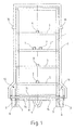
- the carrying device in Fig. 1 has a composite of metal profiles support frame 1.
- the support frame 1 is equipped with wheels 2, on this and on projections 3, 4 it stands on the ground, not shown.
- the support frame 1 comprises horizontally arranged frame sections 5, 5 '. At the frame sections 5 tabs 6 are arranged for attachment of straps for loads.
- the frame portion 5 ' has loops 7 for receiving the shoulder straps to be placed on shoulders.
- a bracket 9 is pivotally received in sleeves 8.
- the bracket 9 is formed as a quadrangular frame, wherein in each case a space 10 is left for the wheels 2.
- a frame portion 11 of the bracket 9 is received in the sleeves 8.
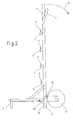
- Fig. 2 is indicated by the arrows 12, 13, the pivoting of the bracket 9.
- the pivoting of the bracket 9 can be done so far, until the frame portion 11 arranged stops 14 abut a frame profile 15.
- Fig. 2 shows that the frame profile 15 is a flat profile. Laying down the bracket 9 in the illustrated state can still be provided on the support frame 1 tube clips 16 for receiving the bracket profiles.
- fastening means are arranged for their attachment and thus for fixing the support means as a whole on fittings, on walls or on motor vehicle superstructures.
- Such fastening means may be formed, for example, hook-like and be suitable for hanging in the bow of a structure above a loading area of a motor vehicle. Just when the carrying device is suspended in a position above a loading area, it is already prepared for a comfortable placement on the back of a wearer.
Landscapes
- Handcart (AREA)
Abstract
Description
- Die Erfindung betrifft eine rucksackartige Trageeinrichtung zum Transport von Lasten auf dem Rücken eines Menschen, umfassend ein die Last aufnehmendes Tragegestell sowie auf die Schultern auflegbare Riemen.
- Mit Rucksäcken können Lasten auf dem Rücken getragen werden. Die Last wird über Riemen auf die Schulter des Tragenden übertragen, ein guter Teil der Gewichtskraft wird auch vom Rücken direkt aufgenommen. Nach Art der Rucksäcke konstruierte Tragegestelle finden gleichfalls Anwendung. Sie haben ein Tragegestell für Lasten, an der der Last gegenüberliegenden Seite des Tragegestells sind wieder Riemen angeordnet, die auf den Rücken eines Menschen zum Tragen des Tragegestells aufgelegt werden können.
- Insbesondere dann, wenn das Tragegestell mit schweren Lasten belegt ist, beispielsweise Werkzeugkoffern, ist das Aufnehmen der Trageeinrichtung bzw. das Absetzen der Trageeinrichtung erschwert. Die Folge können Verletzungen oder muskuläre Schäden bzw. Schäden des Bewegungsapparates sein. Gegebenenfalls können Lasten unkontrolliert abgesetzt werden und dabei Schäden erleiden.
- Der Erfindung liegt die Aufgabe zu Grunde, eine Trageeinrichtung der eingangs genannten Gattung aufzuzeigen, deren Aufnehmen auf den Rücken eines Menschen bzw. deren Absetzen auf den Boden erleichtert ist.
- Diese Aufgabe ist erfindungsgemäß dadurch gelöst, dass an dem Tragegestell in dessen Aufstellbereich auf dem Boden zumindest ein Bügel um eine horizontale Achse schwenkbar angelenkt ist.
- Bei der erfindungsgemäßen Trageeinrichtung ist zum Aufstellen derselben nicht nur ein Aufstellbereich am Tragegestell vorgesehen, sondern noch ein Bügel. Dieser Bügel, der ein Stützbügel ist, ist um eine horizontale Achse schwenkbar im Aufstellbereich angelenkt. Wird die Trageeinrichtung auf dem Rücken getragen, so kann der Bügel in der Weise um die horizontale Achse geschwenkt werden, dass er sich am Ende der Schwenkbewegung in einer Position unterhalb der Trageeinrichtung befindet. Ein Absetzen der Trageeinrichtung kann dann zunächst nur auf diesem Bügel erfolgen, nämlich dann, wenn die Trageeinrichtung selbst noch in einer Höhe oberhalb auf dem Boden angeordnet ist, die beispielsweise ein Tragen auf dem Rücken noch ermöglicht. Die Trageeinrichtung wird also zunächst mit dem Richtung Boden geschwenkten Bügel auf dem Boden abgestützt, anschließend kann sie dann durch ein Schwenken des Bügels kontrolliert zum Boden geführt werden.
- Der Bügel kann aber auch beim Aufsetzen der Trageeinrichtung auf dem Rücken helfen. Wenn die Trageeinrichtung auf dem Boden steht, kann der Bügel auf den Boden geschwenkt werden und beispielsweise mit dem Fuß eines die Trageeinrichtung Aufnehmenden fixiert werden. Die Trageeinrichtung kann dann von dem Aufnehmenden angehoben und zu sich herangezogen werden, dabei bleibt der Bügel auf dem Erdboden stehen und nimmt Gewichtskräfte auf. Befindet sich die Trageeinrichtung oberhalb des auf dem Boden aufstehenden Bügels, kann ein vorsichtiges Aufsetzen der Trageeinrichtung mit den Riemen auf den Schultern des Aufnehmenden bzw. des Tragenden erfolgen, anschließend kann der Bügel dann vom Boden hochgeschwenkt werden und in einem hochgeschwenkten Zustand beispielsweise an der Trageeinrichtung festgelegt werden.
- Der am Tragegestell angeordnete Bügel erleichtert somit das Absetzen des Tragegestells sowie das Wiederaufnehmen des Tragegestells.
- Nach einer ersten Weiterbildung der Erfindung ist vorgesehen, dass der Bügel als geschlossener Rahmen ausgebildet ist, wobei ein Rahmenabschnitt an dem Tragegestell schwenkbar gelagert ist. Das Tragegestell hat beispielsweise Hülsen, in denen ein Rahmenabschnitt aufgenommen ist. Der Rahmen kann eine viereckige Ausbildung haben, beim Aufstehen auf dem Boden verläuft dann ein Rahmenabschnitt quer zum Boden in unmittelbarer Auflage auf dem Boden, während zwei parallel zueinander angeordnete Rahmenabschnitte vertikal auf dem Boden aufstehen und zwischen sich den am Tragegestell schwenkbar gelagerten Rahmenabschnitt aufnehmen. Der Bügel hat in dieser Bauweise eine stabile Konstruktion, welche die Gewichtskräfte der Trageeinrichtung aufnehmen kann.
- Auf dem schwenkbar gelagerten Rahmenabschnitt ist zumindest ein Anschlagelement angeordnet, während das Tragegestell einen Anschlagbereich für das Anschlagelement hat. Mit diesem Anschlagelement ist verhindert, dass der Bügel um 360° herumgeschwenkt werden kann. Die Schwenkbewegung ist dadurch begrenzt, es können definierte Situation hergestellt werden, in denen das Anschlagelement am Anschlagbereich anliegt, beispielsweise beim Absetzen des Tragegestells. Der Anschlagbereich des Tragegestells ist beispielsweise durch ein Gestellprofil ausgebildet, das sich vorzugsweise über die gesamte Breite des Tragegestells erstreckt. Somit können auf dem Rahmenabschnitt mehrere Anschlagelemente angeordnet sein, die z. B. jeweils als Lasche ausgebildet sind.
- Der Bügel hat vorzugsweise eine Bauhöhe von etwa ≥ 1 m. Damit ermöglicht er das Anordnen der Trageeinrichtung in einer größeren Höhe, wenn er auf dem Boden aufsteht. Bei einem Hochschwenken des Bügels kann dies aufgrund des Anschlages beispielsweise nach vorn und weiter über den Kopf des die Trageeinrichtung Tragenden hinweg erfolgen.
- Im Bereich der schwenkbaren Anlenkung kann die Trageeinrichtung Räder aufweisen, so dass sie auch als Karre benutzt werden kann. Die Bauteile einschließlich des Bügels können aus Stahlrohr gefertigt sein, so dass insgesamt eine hohe Festigkeit gegeben ist.
- Ein Ausführungsbeispiel der Erfindung, aus dem sich weitere erfinderische Merkmale ergeben, ist in der Zeichnung dargestellt. Es zeigen:
- Fig. 1:
- eine Seitenansicht einer erfindungsgemäßen Trageeinrichtung zum Transport von Lasten und
- Fig. 2:
- eine weitere Seitenansicht der Trageeinrichtung nach
Fig. 1 . - Die Trageeinrichtung in
Fig. 1 hat ein aus Metallprofilen zusammengesetztes Tragegestell 1. Das Tragegestell 1 ist mit Rädern 2 ausgerüstet, über diese sowie über Vorsprünge 3, 4 steht es auf dem nicht weiter dargestellten Boden auf. Das Tragegestell 1 umfasst horizontal angeordnete Gestellabschnitte 5, 5'. An den Gestellabschnitten 5 sind Laschen 6 zur Befestigung von Gurten für Lasten angeordnet. Der Gestellabschnitt 5' dagegen weist Schlaufen 7 zur Aufnahme der auf Schultern aufzulegenden Tragriemen auf. - Im Aufstellbereich des Tragegestells 1 ist in Hülsen 8 ein Bügel 9 schwenkbar aufgenommen. Der Bügel 9 ist als viereckiger Rahmen ausgebildet, wobei jeweils ein Bauraum 10 für die Räder 2 gelassen wird. In der Schwenkachse des Bügels 9 ist ein Rahmenabschnitt 11 des Bügels 9 in den Hülsen 8 aufgenommen.
- In
Fig. 2 ist durch die Pfeile 12, 13 das Verschwenken des Bügels 9 angedeutet. Das Verschwenken des Bügels 9 kann dabei soweit erfolgen, bis an dem Rahmenabschnitt 11 angeordnete Anschläge 14 an einem Gestellprofil 15 anschlagen.Fig. 2 zeigt, dass das Gestell profil 15 ein Flachprofil ist. Zur Festlegung des Bügels 9 im dargestellten Zustand können an dem Tragegestell 1 noch Rohrclipse 16 zur Aufnahme der Bügelprofile vorgesehen sein. - Es kann noch vorgesehen sein, dass am Tragegestell 1 oder am Bügel 9 Befestigungsmittel zu ihrem Befestigen und damit zum Befestigen der Trageeinrichtung insgesamt an Beschlägen, an Wänden oder an Kraftfahrzeugaufbauten angeordnet sind. Derartige Befestigungsmittel können beispielsweise hakenartig ausgebildet sein und zum Einhängen in die Spriegel eines Aufbaus oberhalb einer Ladefläche eines Kraftfahrzeuges geeignet sein. Gerade dann, wenn die Trageeinrichtung in einer Lage oberhalb einer Ladefläche aufgehängt wird, ist sie bereits für ein bequemes Aufsetzen auf den Rücken eines Tragenden vorbereitet.
Claims (7)
- Rucksackartige Trageeinrichtung zum Transport von Lasten auf dem Rücken eines Menschen, umfassend ein die Last aufnehmendes Tragegestell sowie auf die Schultern auflegbare Riemen,
dadurch gekennzeichnet,
dass an dem Tragegestell (1) in dessen Aufstellbereich auf dem Boden zumindest ein Bügel (9) um eine horizontale Achse schwenkbar angelenkt ist. - Trageeinrichtung nach Anspruch 1, dadurch gekennzeichnet, dass der Bügel (9) als geschlossener Rahmen ausgebildet ist, wobei ein Rahmenabschnitt (11) an dem Tragegestell (1) schwenkbar gelagert ist.
- Trageeinrichtung nach Anspruch 2, dadurch gekennzeichnet, dass auf dem schwenkbar gelagerten Rahmenabschnitt (11) zumindest ein Anschlagelement (14) angeordnet ist und das Tragegestell (1) einen Anschlagbereich für dieses Anschlagelement (14) hat.
- Trageeinrichtung nach Anspruch 3, dadurch gekennzeichnet, dass der Anschlagbereich des Tragegestells (1) durch ein Gestell profil (15) ausgebildet ist.
- Trageeinrichtung nach einem der vorhergehenden Ansprüche, dadurch gekennzeichnet, dass der Bügel (9) eine Bauhöhe von etwa ≥ 1 m hat.
- Trageeinrichtung nach einem der vorhergehenden Ansprüche, dadurch gekennzeichnet, dass es im Bereich der schwenkbaren Anlenkung des Bügels (9) Räder (2) aufweist.
- Trageeinrichtung nach einem der vorhergehenden Ansprüche, dadurch gekennzeichnet, dass seine Bauteile einschließlich des Bügels (9) aus Stahlrohr gefertigt sind.
Applications Claiming Priority (1)
| Application Number | Priority Date | Filing Date | Title |
|---|---|---|---|
| DE102013001742.4A DE102013001742A1 (de) | 2013-02-01 | 2013-02-01 | Rucksackartige Trageeinrichtung zum Transport von Lasten auf dem Rücken eines Menschen |
Publications (2)
| Publication Number | Publication Date |
|---|---|
| EP2762032A1 true EP2762032A1 (de) | 2014-08-06 |
| EP2762032B1 EP2762032B1 (de) | 2020-08-19 |
Family
ID=50070343
Family Applications (1)
| Application Number | Title | Priority Date | Filing Date |
|---|---|---|---|
| EP14153660.7A Active EP2762032B1 (de) | 2013-02-01 | 2014-02-03 | Rucksackartige Trageeinrichtung zum Transport von Lasten auf dem Rücken eines Menschen |
Country Status (2)
| Country | Link |
|---|---|
| EP (1) | EP2762032B1 (de) |
| DE (1) | DE102013001742A1 (de) |
Cited By (1)
| Publication number | Priority date | Publication date | Assignee | Title |
|---|---|---|---|---|
| EP3357371A1 (de) * | 2017-02-03 | 2018-08-08 | AFR Engineering GmbH | Rucksacktragesystem zum freihändigen rückentransport eines fahrrades |
Citations (2)
| Publication number | Priority date | Publication date | Assignee | Title |
|---|---|---|---|---|
| DE8334873U1 (de) * | 1983-12-06 | 1984-04-12 | Grässle, Wilhelm, 7240 Horb | Fahrbares traggestell |
| KR20090119947A (ko) * | 2009-10-19 | 2009-11-23 | 이기동 | 접이식 지게 |
-
2013
- 2013-02-01 DE DE102013001742.4A patent/DE102013001742A1/de not_active Withdrawn
-
2014
- 2014-02-03 EP EP14153660.7A patent/EP2762032B1/de active Active
Patent Citations (2)
| Publication number | Priority date | Publication date | Assignee | Title |
|---|---|---|---|---|
| DE8334873U1 (de) * | 1983-12-06 | 1984-04-12 | Grässle, Wilhelm, 7240 Horb | Fahrbares traggestell |
| KR20090119947A (ko) * | 2009-10-19 | 2009-11-23 | 이기동 | 접이식 지게 |
Cited By (1)
| Publication number | Priority date | Publication date | Assignee | Title |
|---|---|---|---|---|
| EP3357371A1 (de) * | 2017-02-03 | 2018-08-08 | AFR Engineering GmbH | Rucksacktragesystem zum freihändigen rückentransport eines fahrrades |
Also Published As
| Publication number | Publication date |
|---|---|
| EP2762032B1 (de) | 2020-08-19 |
| DE102013001742A1 (de) | 2014-08-07 |
Similar Documents
| Publication | Publication Date | Title |
|---|---|---|
| DE202011110856U1 (de) | Zusammenklappbare Karosserie für manuell getriebene Trägerfahrzeuge zum Überfahren von Hindernissen | |
| DE102018007249B4 (de) | Aufnahmevorrichtung für Transportboxen | |
| DE202011004150U1 (de) | Einspur-Anhänger | |
| EP2762032B1 (de) | Rucksackartige Trageeinrichtung zum Transport von Lasten auf dem Rücken eines Menschen | |
| EP2975965B1 (de) | Vorrichtung für traggestelle | |
| DE202008017142U1 (de) | Fahrzeug mit Rahmen und auf dem Rahmen befindlichen Ladeboden | |
| DE102005034313B4 (de) | Als Sack- und Schubkarre verwendbare Transportkarre | |
| AT505650B1 (de) | Schneidwerk für einen mähdrescher | |
| DE102014001106B3 (de) | In eine Transportkarre umwandelbare Klappleiter | |
| DE102008029573B4 (de) | Mit Rädern versehene Rucksack-Vorrichtung | |
| DE2922129A1 (de) | Mehrzweck- anlagen- gestaltungselement | |
| EP3445209B1 (de) | Tragvorrichtung zum tragen zumindest einer sich auf ihr befindlichen person | |
| DE202018100968U1 (de) | Auto-Einstiegshilfe für Hunde | |
| EP2242467B1 (de) | Transportvorrichtung | |
| DE102016110306A1 (de) | Transportvorrichtung für Tauchsportausrüstung | |
| DE8812022U1 (de) | Wagen zum Transport von Gepäck | |
| DE69917187T2 (de) | Ein Stützrahmen | |
| DE202021103146U1 (de) | Rampenvorrichtung | |
| DE202014000803U1 (de) | In eine Transportkarre umwandelbare Klappleiter | |
| DE2108124A1 (de) | Haltevorrichtung fur Scheiben stapel | |
| DE2236827C3 (de) | Tragenbühnengestell, insbesondere in Krankenwagen | |
| DE20006027U1 (de) | Handkarren zum Entfernen von Tier-Kadavern, insbesondere von Schweine-Kadavern aus dem Sauenstall | |
| EP1231124B1 (de) | Schubkarre mit beweglicher Transportwanne | |
| AT14030U1 (de) | Roller mit Tasche | |
| DE202012006078U1 (de) | Transportgestell für eine Tragelast |
Legal Events
| Date | Code | Title | Description |
|---|---|---|---|
| PUAI | Public reference made under article 153(3) epc to a published international application that has entered the european phase |
Free format text: ORIGINAL CODE: 0009012 |
|
| 17P | Request for examination filed |
Effective date: 20140203 |
|
| AK | Designated contracting states |
Kind code of ref document: A1 Designated state(s): AL AT BE BG CH CY CZ DE DK EE ES FI FR GB GR HR HU IE IS IT LI LT LU LV MC MK MT NL NO PL PT RO RS SE SI SK SM TR |
|
| AX | Request for extension of the european patent |
Extension state: BA ME |
|
| R17P | Request for examination filed (corrected) |
Effective date: 20140904 |
|
| RBV | Designated contracting states (corrected) |
Designated state(s): AL AT BE BG CH CY CZ DE DK EE ES FI FR GB GR HR HU IE IS IT LI LT LU LV MC MK MT NL NO PL PT RO RS SE SI SK SM TR |
|
| STAA | Information on the status of an ep patent application or granted ep patent |
Free format text: STATUS: EXAMINATION IS IN PROGRESS |
|
| 17Q | First examination report despatched |
Effective date: 20170919 |
|
| GRAP | Despatch of communication of intention to grant a patent |
Free format text: ORIGINAL CODE: EPIDOSNIGR1 |
|
| STAA | Information on the status of an ep patent application or granted ep patent |
Free format text: STATUS: GRANT OF PATENT IS INTENDED |
|
| INTG | Intention to grant announced |
Effective date: 20200331 |
|
| GRAS | Grant fee paid |
Free format text: ORIGINAL CODE: EPIDOSNIGR3 |
|
| GRAA | (expected) grant |
Free format text: ORIGINAL CODE: 0009210 |
|
| STAA | Information on the status of an ep patent application or granted ep patent |
Free format text: STATUS: THE PATENT HAS BEEN GRANTED |
|
| AK | Designated contracting states |
Kind code of ref document: B1 Designated state(s): AL AT BE BG CH CY CZ DE DK EE ES FI FR GB GR HR HU IE IS IT LI LT LU LV MC MK MT NL NO PL PT RO RS SE SI SK SM TR |
|
| REG | Reference to a national code |
Ref country code: GB Ref legal event code: FG4D Free format text: NOT ENGLISH |
|
| REG | Reference to a national code |
Ref country code: CH Ref legal event code: EP |
|
| REG | Reference to a national code |
Ref country code: DE Ref legal event code: R096 Ref document number: 502014014635 Country of ref document: DE |
|
| REG | Reference to a national code |
Ref country code: AT Ref legal event code: REF Ref document number: 1302958 Country of ref document: AT Kind code of ref document: T Effective date: 20200915 |
|
| REG | Reference to a national code |
Ref country code: IE Ref legal event code: FG4D Free format text: LANGUAGE OF EP DOCUMENT: GERMAN |
|
| REG | Reference to a national code |
Ref country code: LT Ref legal event code: MG4D |
|
| REG | Reference to a national code |
Ref country code: NL Ref legal event code: MP Effective date: 20200819 |
|
| PG25 | Lapsed in a contracting state [announced via postgrant information from national office to epo] |
Ref country code: PT Free format text: LAPSE BECAUSE OF FAILURE TO SUBMIT A TRANSLATION OF THE DESCRIPTION OR TO PAY THE FEE WITHIN THE PRESCRIBED TIME-LIMIT Effective date: 20201221 Ref country code: NO Free format text: LAPSE BECAUSE OF FAILURE TO SUBMIT A TRANSLATION OF THE DESCRIPTION OR TO PAY THE FEE WITHIN THE PRESCRIBED TIME-LIMIT Effective date: 20201119 Ref country code: FI Free format text: LAPSE BECAUSE OF FAILURE TO SUBMIT A TRANSLATION OF THE DESCRIPTION OR TO PAY THE FEE WITHIN THE PRESCRIBED TIME-LIMIT Effective date: 20200819 Ref country code: BG Free format text: LAPSE BECAUSE OF FAILURE TO SUBMIT A TRANSLATION OF THE DESCRIPTION OR TO PAY THE FEE WITHIN THE PRESCRIBED TIME-LIMIT Effective date: 20201119 Ref country code: SE Free format text: LAPSE BECAUSE OF FAILURE TO SUBMIT A TRANSLATION OF THE DESCRIPTION OR TO PAY THE FEE WITHIN THE PRESCRIBED TIME-LIMIT Effective date: 20200819 Ref country code: LT Free format text: LAPSE BECAUSE OF FAILURE TO SUBMIT A TRANSLATION OF THE DESCRIPTION OR TO PAY THE FEE WITHIN THE PRESCRIBED TIME-LIMIT Effective date: 20200819 Ref country code: HR Free format text: LAPSE BECAUSE OF FAILURE TO SUBMIT A TRANSLATION OF THE DESCRIPTION OR TO PAY THE FEE WITHIN THE PRESCRIBED TIME-LIMIT Effective date: 20200819 Ref country code: GR Free format text: LAPSE BECAUSE OF FAILURE TO SUBMIT A TRANSLATION OF THE DESCRIPTION OR TO PAY THE FEE WITHIN THE PRESCRIBED TIME-LIMIT Effective date: 20201120 |
|
| PG25 | Lapsed in a contracting state [announced via postgrant information from national office to epo] |
Ref country code: IS Free format text: LAPSE BECAUSE OF FAILURE TO SUBMIT A TRANSLATION OF THE DESCRIPTION OR TO PAY THE FEE WITHIN THE PRESCRIBED TIME-LIMIT Effective date: 20201219 Ref country code: PL Free format text: LAPSE BECAUSE OF FAILURE TO SUBMIT A TRANSLATION OF THE DESCRIPTION OR TO PAY THE FEE WITHIN THE PRESCRIBED TIME-LIMIT Effective date: 20200819 Ref country code: RS Free format text: LAPSE BECAUSE OF FAILURE TO SUBMIT A TRANSLATION OF THE DESCRIPTION OR TO PAY THE FEE WITHIN THE PRESCRIBED TIME-LIMIT Effective date: 20200819 Ref country code: LV Free format text: LAPSE BECAUSE OF FAILURE TO SUBMIT A TRANSLATION OF THE DESCRIPTION OR TO PAY THE FEE WITHIN THE PRESCRIBED TIME-LIMIT Effective date: 20200819 Ref country code: NL Free format text: LAPSE BECAUSE OF FAILURE TO SUBMIT A TRANSLATION OF THE DESCRIPTION OR TO PAY THE FEE WITHIN THE PRESCRIBED TIME-LIMIT Effective date: 20200819 |
|
| PG25 | Lapsed in a contracting state [announced via postgrant information from national office to epo] |
Ref country code: RO Free format text: LAPSE BECAUSE OF FAILURE TO SUBMIT A TRANSLATION OF THE DESCRIPTION OR TO PAY THE FEE WITHIN THE PRESCRIBED TIME-LIMIT Effective date: 20200819 Ref country code: SM Free format text: LAPSE BECAUSE OF FAILURE TO SUBMIT A TRANSLATION OF THE DESCRIPTION OR TO PAY THE FEE WITHIN THE PRESCRIBED TIME-LIMIT Effective date: 20200819 Ref country code: EE Free format text: LAPSE BECAUSE OF FAILURE TO SUBMIT A TRANSLATION OF THE DESCRIPTION OR TO PAY THE FEE WITHIN THE PRESCRIBED TIME-LIMIT Effective date: 20200819 Ref country code: CZ Free format text: LAPSE BECAUSE OF FAILURE TO SUBMIT A TRANSLATION OF THE DESCRIPTION OR TO PAY THE FEE WITHIN THE PRESCRIBED TIME-LIMIT Effective date: 20200819 Ref country code: DK Free format text: LAPSE BECAUSE OF FAILURE TO SUBMIT A TRANSLATION OF THE DESCRIPTION OR TO PAY THE FEE WITHIN THE PRESCRIBED TIME-LIMIT Effective date: 20200819 |
|
| REG | Reference to a national code |
Ref country code: DE Ref legal event code: R097 Ref document number: 502014014635 Country of ref document: DE |
|
| PG25 | Lapsed in a contracting state [announced via postgrant information from national office to epo] |
Ref country code: ES Free format text: LAPSE BECAUSE OF FAILURE TO SUBMIT A TRANSLATION OF THE DESCRIPTION OR TO PAY THE FEE WITHIN THE PRESCRIBED TIME-LIMIT Effective date: 20200819 Ref country code: AL Free format text: LAPSE BECAUSE OF FAILURE TO SUBMIT A TRANSLATION OF THE DESCRIPTION OR TO PAY THE FEE WITHIN THE PRESCRIBED TIME-LIMIT Effective date: 20200819 |
|
| PLBE | No opposition filed within time limit |
Free format text: ORIGINAL CODE: 0009261 |
|
| STAA | Information on the status of an ep patent application or granted ep patent |
Free format text: STATUS: NO OPPOSITION FILED WITHIN TIME LIMIT |
|
| PG25 | Lapsed in a contracting state [announced via postgrant information from national office to epo] |
Ref country code: SK Free format text: LAPSE BECAUSE OF FAILURE TO SUBMIT A TRANSLATION OF THE DESCRIPTION OR TO PAY THE FEE WITHIN THE PRESCRIBED TIME-LIMIT Effective date: 20200819 |
|
| 26N | No opposition filed |
Effective date: 20210520 |
|
| PG25 | Lapsed in a contracting state [announced via postgrant information from national office to epo] |
Ref country code: SI Free format text: LAPSE BECAUSE OF FAILURE TO SUBMIT A TRANSLATION OF THE DESCRIPTION OR TO PAY THE FEE WITHIN THE PRESCRIBED TIME-LIMIT Effective date: 20200819 |
|
| PG25 | Lapsed in a contracting state [announced via postgrant information from national office to epo] |
Ref country code: MC Free format text: LAPSE BECAUSE OF FAILURE TO SUBMIT A TRANSLATION OF THE DESCRIPTION OR TO PAY THE FEE WITHIN THE PRESCRIBED TIME-LIMIT Effective date: 20200819 |
|
| REG | Reference to a national code |
Ref country code: BE Ref legal event code: MM Effective date: 20210228 |
|
| PG25 | Lapsed in a contracting state [announced via postgrant information from national office to epo] |
Ref country code: LI Free format text: LAPSE BECAUSE OF NON-PAYMENT OF DUE FEES Effective date: 20210228 Ref country code: LU Free format text: LAPSE BECAUSE OF NON-PAYMENT OF DUE FEES Effective date: 20210203 Ref country code: CH Free format text: LAPSE BECAUSE OF NON-PAYMENT OF DUE FEES Effective date: 20210228 |
|
| PG25 | Lapsed in a contracting state [announced via postgrant information from national office to epo] |
Ref country code: IE Free format text: LAPSE BECAUSE OF NON-PAYMENT OF DUE FEES Effective date: 20210203 |
|
| PG25 | Lapsed in a contracting state [announced via postgrant information from national office to epo] |
Ref country code: BE Free format text: LAPSE BECAUSE OF NON-PAYMENT OF DUE FEES Effective date: 20210228 |
|
| PG25 | Lapsed in a contracting state [announced via postgrant information from national office to epo] |
Ref country code: HU Free format text: LAPSE BECAUSE OF FAILURE TO SUBMIT A TRANSLATION OF THE DESCRIPTION OR TO PAY THE FEE WITHIN THE PRESCRIBED TIME-LIMIT; INVALID AB INITIO Effective date: 20140203 |
|
| PG25 | Lapsed in a contracting state [announced via postgrant information from national office to epo] |
Ref country code: CY Free format text: LAPSE BECAUSE OF FAILURE TO SUBMIT A TRANSLATION OF THE DESCRIPTION OR TO PAY THE FEE WITHIN THE PRESCRIBED TIME-LIMIT Effective date: 20200819 |
|
| P01 | Opt-out of the competence of the unified patent court (upc) registered |
Effective date: 20230601 |
|
| PG25 | Lapsed in a contracting state [announced via postgrant information from national office to epo] |
Ref country code: MK Free format text: LAPSE BECAUSE OF FAILURE TO SUBMIT A TRANSLATION OF THE DESCRIPTION OR TO PAY THE FEE WITHIN THE PRESCRIBED TIME-LIMIT Effective date: 20200819 |
|
| PGFP | Annual fee paid to national office [announced via postgrant information from national office to epo] |
Ref country code: GB Payment date: 20240222 Year of fee payment: 11 |
|
| PGFP | Annual fee paid to national office [announced via postgrant information from national office to epo] |
Ref country code: IT Payment date: 20240229 Year of fee payment: 11 Ref country code: FR Payment date: 20240222 Year of fee payment: 11 |
|
| PG25 | Lapsed in a contracting state [announced via postgrant information from national office to epo] |
Ref country code: TR Free format text: LAPSE BECAUSE OF FAILURE TO SUBMIT A TRANSLATION OF THE DESCRIPTION OR TO PAY THE FEE WITHIN THE PRESCRIBED TIME-LIMIT Effective date: 20200819 |
|
| PG25 | Lapsed in a contracting state [announced via postgrant information from national office to epo] |
Ref country code: MT Free format text: LAPSE BECAUSE OF FAILURE TO SUBMIT A TRANSLATION OF THE DESCRIPTION OR TO PAY THE FEE WITHIN THE PRESCRIBED TIME-LIMIT Effective date: 20200819 |
|
| GBPC | Gb: european patent ceased through non-payment of renewal fee |
Effective date: 20250203 |
|
| PG25 | Lapsed in a contracting state [announced via postgrant information from national office to epo] |
Ref country code: GB Free format text: LAPSE BECAUSE OF NON-PAYMENT OF DUE FEES Effective date: 20250203 |
|
| PG25 | Lapsed in a contracting state [announced via postgrant information from national office to epo] |
Ref country code: FR Free format text: LAPSE BECAUSE OF NON-PAYMENT OF DUE FEES Effective date: 20250228 Ref country code: IT Free format text: LAPSE BECAUSE OF NON-PAYMENT OF DUE FEES Effective date: 20250203 |
|
| PGFP | Annual fee paid to national office [announced via postgrant information from national office to epo] |
Ref country code: DE Payment date: 20260213 Year of fee payment: 13 |
|
| PGFP | Annual fee paid to national office [announced via postgrant information from national office to epo] |
Ref country code: AT Payment date: 20260216 Year of fee payment: 13 |