EP2760592B1 - Dosierspender - Google Patents
Dosierspender Download PDFInfo
- Publication number
- EP2760592B1 EP2760592B1 EP11810595.6A EP11810595A EP2760592B1 EP 2760592 B1 EP2760592 B1 EP 2760592B1 EP 11810595 A EP11810595 A EP 11810595A EP 2760592 B1 EP2760592 B1 EP 2760592B1
- Authority
- EP
- European Patent Office
- Prior art keywords
- guide
- housing
- latching
- transmission element
- dispenser according
- Prior art date
- Legal status (The legal status is an assumption and is not a legal conclusion. Google has not performed a legal analysis and makes no representation as to the accuracy of the status listed.)
- Not-in-force
Links
Images



Classifications
-
- B—PERFORMING OPERATIONS; TRANSPORTING
- B67—OPENING, CLOSING OR CLEANING BOTTLES, JARS OR SIMILAR CONTAINERS; LIQUID HANDLING
- B67D—DISPENSING, DELIVERING OR TRANSFERRING LIQUIDS, NOT OTHERWISE PROVIDED FOR
- B67D1/00—Apparatus or devices for dispensing beverages on draught
- B67D1/0015—Apparatus or devices for dispensing beverages on draught the beverage being prepared by mixing at least two liquid components
- B67D1/0021—Apparatus or devices for dispensing beverages on draught the beverage being prepared by mixing at least two liquid components the components being mixed at the time of dispensing, i.e. post-mix dispensers
- B67D1/0022—Apparatus or devices for dispensing beverages on draught the beverage being prepared by mixing at least two liquid components the components being mixed at the time of dispensing, i.e. post-mix dispensers the apparatus comprising means for automatically controlling the amount to be dispensed
- B67D1/0034—Apparatus or devices for dispensing beverages on draught the beverage being prepared by mixing at least two liquid components the components being mixed at the time of dispensing, i.e. post-mix dispensers the apparatus comprising means for automatically controlling the amount to be dispensed for controlling the amount of each component
- B67D1/0035—Apparatus or devices for dispensing beverages on draught the beverage being prepared by mixing at least two liquid components the components being mixed at the time of dispensing, i.e. post-mix dispensers the apparatus comprising means for automatically controlling the amount to be dispensed for controlling the amount of each component the controls being based on the same metering technics
- B67D1/0037—Apparatus or devices for dispensing beverages on draught the beverage being prepared by mixing at least two liquid components the components being mixed at the time of dispensing, i.e. post-mix dispensers the apparatus comprising means for automatically controlling the amount to be dispensed for controlling the amount of each component the controls being based on the same metering technics based on volumetric dosing
-
- B—PERFORMING OPERATIONS; TRANSPORTING
- B05—SPRAYING OR ATOMISING IN GENERAL; APPLYING FLUENT MATERIALS TO SURFACES, IN GENERAL
- B05C—APPARATUS FOR APPLYING FLUENT MATERIALS TO SURFACES, IN GENERAL
- B05C17/00—Hand tools or apparatus using hand held tools, for applying liquids or other fluent materials to, for spreading applied liquids or other fluent materials on, or for partially removing applied liquids or other fluent materials from, surfaces
- B05C17/005—Hand tools or apparatus using hand held tools, for applying liquids or other fluent materials to, for spreading applied liquids or other fluent materials on, or for partially removing applied liquids or other fluent materials from, surfaces for discharging material from a reservoir or container located in or on the hand tool through an outlet orifice by pressure without using surface contacting members like pads or brushes
- B05C17/00553—Hand tools or apparatus using hand held tools, for applying liquids or other fluent materials to, for spreading applied liquids or other fluent materials on, or for partially removing applied liquids or other fluent materials from, surfaces for discharging material from a reservoir or container located in or on the hand tool through an outlet orifice by pressure without using surface contacting members like pads or brushes with means allowing the stock of material to consist of at least two different components
-
- B—PERFORMING OPERATIONS; TRANSPORTING
- B05—SPRAYING OR ATOMISING IN GENERAL; APPLYING FLUENT MATERIALS TO SURFACES, IN GENERAL
- B05B—SPRAYING APPARATUS; ATOMISING APPARATUS; NOZZLES
- B05B11/00—Single-unit hand-held apparatus in which flow of contents is produced by the muscular force of the operator at the moment of use
- B05B11/0005—Components or details
- B05B11/0037—Containers
- B05B11/0038—Inner container disposed in an outer shell or outer casing
-
- B—PERFORMING OPERATIONS; TRANSPORTING
- B05—SPRAYING OR ATOMISING IN GENERAL; APPLYING FLUENT MATERIALS TO SURFACES, IN GENERAL
- B05B—SPRAYING APPARATUS; ATOMISING APPARATUS; NOZZLES
- B05B11/00—Single-unit hand-held apparatus in which flow of contents is produced by the muscular force of the operator at the moment of use
- B05B11/01—Single-unit hand-held apparatus in which flow of contents is produced by the muscular force of the operator at the moment of use characterised by the means producing the flow
- B05B11/10—Pump arrangements for transferring the contents from the container to a pump chamber by a sucking effect and forcing the contents out through the dispensing nozzle
- B05B11/1001—Piston pumps
- B05B11/1004—Piston pumps comprising a movable cylinder and a stationary piston
-
- B—PERFORMING OPERATIONS; TRANSPORTING
- B05—SPRAYING OR ATOMISING IN GENERAL; APPLYING FLUENT MATERIALS TO SURFACES, IN GENERAL
- B05B—SPRAYING APPARATUS; ATOMISING APPARATUS; NOZZLES
- B05B11/00—Single-unit hand-held apparatus in which flow of contents is produced by the muscular force of the operator at the moment of use
- B05B11/01—Single-unit hand-held apparatus in which flow of contents is produced by the muscular force of the operator at the moment of use characterised by the means producing the flow
- B05B11/10—Pump arrangements for transferring the contents from the container to a pump chamber by a sucking effect and forcing the contents out through the dispensing nozzle
- B05B11/1001—Piston pumps
- B05B11/1015—Piston pumps actuated without substantial movement of the nozzle in the direction of the pressure stroke
-
- B—PERFORMING OPERATIONS; TRANSPORTING
- B05—SPRAYING OR ATOMISING IN GENERAL; APPLYING FLUENT MATERIALS TO SURFACES, IN GENERAL
- B05B—SPRAYING APPARATUS; ATOMISING APPARATUS; NOZZLES
- B05B11/00—Single-unit hand-held apparatus in which flow of contents is produced by the muscular force of the operator at the moment of use
- B05B11/01—Single-unit hand-held apparatus in which flow of contents is produced by the muscular force of the operator at the moment of use characterised by the means producing the flow
- B05B11/10—Pump arrangements for transferring the contents from the container to a pump chamber by a sucking effect and forcing the contents out through the dispensing nozzle
- B05B11/1042—Components or details
- B05B11/1052—Actuation means
-
- B—PERFORMING OPERATIONS; TRANSPORTING
- B05—SPRAYING OR ATOMISING IN GENERAL; APPLYING FLUENT MATERIALS TO SURFACES, IN GENERAL
- B05B—SPRAYING APPARATUS; ATOMISING APPARATUS; NOZZLES
- B05B11/00—Single-unit hand-held apparatus in which flow of contents is produced by the muscular force of the operator at the moment of use
- B05B11/01—Single-unit hand-held apparatus in which flow of contents is produced by the muscular force of the operator at the moment of use characterised by the means producing the flow
- B05B11/10—Pump arrangements for transferring the contents from the container to a pump chamber by a sucking effect and forcing the contents out through the dispensing nozzle
- B05B11/1081—Arrangements for pumping several liquids or other fluent materials from several containers, e.g. for mixing them at the moment of pumping
- B05B11/1083—Arrangements for pumping several liquids or other fluent materials from several containers, e.g. for mixing them at the moment of pumping in adjustable proportion
-
- B—PERFORMING OPERATIONS; TRANSPORTING
- B05—SPRAYING OR ATOMISING IN GENERAL; APPLYING FLUENT MATERIALS TO SURFACES, IN GENERAL
- B05B—SPRAYING APPARATUS; ATOMISING APPARATUS; NOZZLES
- B05B11/00—Single-unit hand-held apparatus in which flow of contents is produced by the muscular force of the operator at the moment of use
- B05B11/01—Single-unit hand-held apparatus in which flow of contents is produced by the muscular force of the operator at the moment of use characterised by the means producing the flow
- B05B11/10—Pump arrangements for transferring the contents from the container to a pump chamber by a sucking effect and forcing the contents out through the dispensing nozzle
- B05B11/1081—Arrangements for pumping several liquids or other fluent materials from several containers, e.g. for mixing them at the moment of pumping
- B05B11/1084—Arrangements for pumping several liquids or other fluent materials from several containers, e.g. for mixing them at the moment of pumping each liquid or other fluent material being pumped by a separate pump
-
- B—PERFORMING OPERATIONS; TRANSPORTING
- B05—SPRAYING OR ATOMISING IN GENERAL; APPLYING FLUENT MATERIALS TO SURFACES, IN GENERAL
- B05B—SPRAYING APPARATUS; ATOMISING APPARATUS; NOZZLES
- B05B11/00—Single-unit hand-held apparatus in which flow of contents is produced by the muscular force of the operator at the moment of use
- B05B11/01—Single-unit hand-held apparatus in which flow of contents is produced by the muscular force of the operator at the moment of use characterised by the means producing the flow
- B05B11/10—Pump arrangements for transferring the contents from the container to a pump chamber by a sucking effect and forcing the contents out through the dispensing nozzle
- B05B11/1095—Pump arrangements for transferring the contents from the container to a pump chamber by a sucking effect and forcing the contents out through the dispensing nozzle with movable suction side
-
- B—PERFORMING OPERATIONS; TRANSPORTING
- B05—SPRAYING OR ATOMISING IN GENERAL; APPLYING FLUENT MATERIALS TO SURFACES, IN GENERAL
- B05C—APPARATUS FOR APPLYING FLUENT MATERIALS TO SURFACES, IN GENERAL
- B05C17/00—Hand tools or apparatus using hand held tools, for applying liquids or other fluent materials to, for spreading applied liquids or other fluent materials on, or for partially removing applied liquids or other fluent materials from, surfaces
- B05C17/005—Hand tools or apparatus using hand held tools, for applying liquids or other fluent materials to, for spreading applied liquids or other fluent materials on, or for partially removing applied liquids or other fluent materials from, surfaces for discharging material from a reservoir or container located in or on the hand tool through an outlet orifice by pressure without using surface contacting members like pads or brushes
- B05C17/01—Hand tools or apparatus using hand held tools, for applying liquids or other fluent materials to, for spreading applied liquids or other fluent materials on, or for partially removing applied liquids or other fluent materials from, surfaces for discharging material from a reservoir or container located in or on the hand tool through an outlet orifice by pressure without using surface contacting members like pads or brushes with manually mechanically or electrically actuated piston or the like
- B05C17/0116—Hand tools or apparatus using hand held tools, for applying liquids or other fluent materials to, for spreading applied liquids or other fluent materials on, or for partially removing applied liquids or other fluent materials from, surfaces for discharging material from a reservoir or container located in or on the hand tool through an outlet orifice by pressure without using surface contacting members like pads or brushes with manually mechanically or electrically actuated piston or the like characterised by the piston driving means
- B05C17/012—Stepwise advancing mechanism, e.g. pawl and ratchets
-
- B—PERFORMING OPERATIONS; TRANSPORTING
- B67—OPENING, CLOSING OR CLEANING BOTTLES, JARS OR SIMILAR CONTAINERS; LIQUID HANDLING
- B67D—DISPENSING, DELIVERING OR TRANSFERRING LIQUIDS, NOT OTHERWISE PROVIDED FOR
- B67D1/00—Apparatus or devices for dispensing beverages on draught
- B67D1/08—Details
- B67D1/10—Pump mechanism
- B67D1/101—Pump mechanism of the piston-cylinder type
- B67D1/105—Pump mechanism of the piston-cylinder type for two or more components
-
- B—PERFORMING OPERATIONS; TRANSPORTING
- B67—OPENING, CLOSING OR CLEANING BOTTLES, JARS OR SIMILAR CONTAINERS; LIQUID HANDLING
- B67D—DISPENSING, DELIVERING OR TRANSFERRING LIQUIDS, NOT OTHERWISE PROVIDED FOR
- B67D1/00—Apparatus or devices for dispensing beverages on draught
- B67D1/08—Details
- B67D1/12—Flow or pressure control devices or systems, e.g. valves, gas pressure control, level control in storage containers
- B67D1/1284—Ratio control
- B67D1/1286—Ratio control by mechanical construction
- B67D1/1288—Multi-chamber piston pumps
-
- A—HUMAN NECESSITIES
- A61—MEDICAL OR VETERINARY SCIENCE; HYGIENE
- A61M—DEVICES FOR INTRODUCING MEDIA INTO, OR ONTO, THE BODY; DEVICES FOR TRANSDUCING BODY MEDIA OR FOR TAKING MEDIA FROM THE BODY; DEVICES FOR PRODUCING OR ENDING SLEEP OR STUPOR
- A61M5/00—Devices for bringing media into the body in a subcutaneous, intra-vascular or intramuscular way; Accessories therefor, e.g. filling or cleaning devices, arm-rests
- A61M5/178—Syringes
- A61M5/19—Syringes having more than one chamber, e.g. including a manifold coupling two parallelly aligned syringes through separate channels to a common discharge assembly
-
- A—HUMAN NECESSITIES
- A61—MEDICAL OR VETERINARY SCIENCE; HYGIENE
- A61M—DEVICES FOR INTRODUCING MEDIA INTO, OR ONTO, THE BODY; DEVICES FOR TRANSDUCING BODY MEDIA OR FOR TAKING MEDIA FROM THE BODY; DEVICES FOR PRODUCING OR ENDING SLEEP OR STUPOR
- A61M5/00—Devices for bringing media into the body in a subcutaneous, intra-vascular or intramuscular way; Accessories therefor, e.g. filling or cleaning devices, arm-rests
- A61M5/178—Syringes
- A61M5/31—Details
- A61M5/315—Pistons; Piston-rods; Guiding, blocking or restricting the movement of the rod or piston; Appliances on the rod for facilitating dosing ; Dosing mechanisms
- A61M5/31533—Dosing mechanisms, i.e. setting a dose
- A61M5/31545—Setting modes for dosing
- A61M5/31548—Mechanically operated dose setting member
- A61M5/3155—Mechanically operated dose setting member by rotational movement of dose setting member, e.g. during setting or filling of a syringe
- A61M5/31553—Mechanically operated dose setting member by rotational movement of dose setting member, e.g. during setting or filling of a syringe without axial movement of dose setting member
Definitions
- the invention relates to a metering dispenser for the metered delivery of at least two in each case a reservoir associated components, each reservoir is associated with a conveyor and the conveyors are provided with an actuator for outputting the components of an associated with the reservoir output device, wherein the actuator indirectly via a metering device acts on the conveyors and the metering device is provided with an adjusting device, with the actuation of which the position of a transmission element acting on the conveying element for adjusting the quantitative ratio of the components is variable.
- a metering dispenser of the aforementioned type which has an adjusting device for adjusting the quantity ratio of the components, which has a pivotable about a pivot axis transmission element which acts upon execution of a pivoting movement on the conveyors.
- the pivot axis of the transmission element is rotated about the vertical axis of the metering dispenser by means of an adjusting device.
- the metering is the Issuing the components of the reservoirs on an actuating portion of the transmission element exerted an actuating force, such that due to the action of the actuating force, the transmission element is pivoted about the transverse axis to the longitudinal axis of the dosing dispenser pivot axis.
- the necessary in the known dispenser translational operation for performing a pivoting movement of the transmission element about the transverse axis oriented to the longitudinal axis of the transmission element allows in practice a very inaccurate dosage of output from the output device total amount of the two components.
- the output of a reproducible output quantity of the two components is only possible with the known actuating device upon execution of a complete deflection of the transmission element about the pivot axis.
- the output of only a subset of the maximum possible amount is hardly reproducibly possible because the reproducible output of a subset requires a correspondingly reproducible execution of a partial deflection of the transmission element.
- the execution of a defined deflection of the actuating element is hardly possible with the total only very small path, which performs the transmission element in a pivoting movement.
- the present invention is therefore based on the object to propose a dosing dispenser, which allows accurate dosing of a composite of two components output quantity.
- the dosing dispenser according to the invention has the features of claim 1.
- both the adjusting means for adjusting the quantitative ratio of the components and the actuating device for dispensing the components from the dispensing device are rotatable about their actuation about a longitudinal axis of the metering dispenser.
- the invention is based on the finding that it is much easier for the user of a dispenser for ergonomic reasons, to perform a reproducible rotary motion, as is the case with a translational movement, especially if the for the resolution of the translational movement to Available Stellweg is rather short.
- the adjusting device of the metering device comprises a rotatable adjusting housing about the longitudinal axis of a reservoir housing, in which the reservoirs for receiving the components and the conveyors are accommodated, in which the transmission element is rotationally rigid relative to the adjusting housing and on the longitudinal axis of the StellgePFuses to Operation of the conveyors is arranged axially displaceable, wherein the transmission element has a ring-shaped or formed as a ring segment contact surface, with a circumferentially changing surface contour, which cooperates with the conveyors.
- the special configuration of the adjusting device allows a conversion of an applied by acting on the actuator housing from the outside by the user manual rotational movement of the actuator housing in an axial or translational movement of the transmission element, so on the one hand ergonomically favorable adjustment of the adjusting device by the user possible is, on the other hand by the axial adjusting movement of the transmission element, a functionally reliable operation of the conveyors is possible, in which always the horizontal orientation of the transmission element based on a vertical orientation of the longitudinal axis of the dispenser is maintained.
- the setting of the desired quantity ratio between the two components provided for the output takes place only by a rotation of the transmission element about the vertical axis of the dosing dispenser or the adjusting housing until the relative position of the transmission element with respect to the conveyors is reached, in which the different Contact points of the transmission element are associated with the conveyors.
- the actuating device for outputting the components may comprise a housing rotatable about the longitudinal axis of the dosing relative to the actuator housing, which is provided with a guide arrangement for axial displacement of the transmission element, wherein a first formed in the actuator housing guide means of the guide assembly for converting a rotational movement of the actuator housing in a axial movement of the transmission element cooperates with a second independently of the actuating housing formed guide means of the guide assembly.
- the second guide means comprises a guide member with an axially oriented guide slot and a pin assembly positioned on the transmission element with at least one radial guide pin which penetrates the guide slot and with its contact end with the first guide means the actuating housing cooperates.
- the actuating housing for forming the first guide means on its coaxial with the guide part of the actuating housing arranged inner wall has a guide track with a cooperating with the contact end of the guide pin contact contour which controls the axial movement of the transmission element, so that due to the coaxial arrangement of the Actuator housing to the actuator housing a total compact design of the dispenser is possible.
- a direction of rotation lock or definition of a possible direction of rotation can be achieved if the axially aligned guide slot formed in the guide part has at its lower end for defining a direction of rotation of the actuating device a pin catch for receiving the radial guide pin.
- a particularly advantageous embodiment of the dosing dispenser which contributes to a further increase in the reproducibility of defined dispensing quantities of the dispenser, has a spring device between a stop formed on the guide part and the transmission element for defining a starting position of the actuating device in which the conveying devices are not acted upon by the transmission element on, so that the starting position for the user is characterized haptically accurately detected that in the initial position resistance to the rotational adjustment of the actuator is minimized.
- the stop is formed at the axial end of a arranged at the bottom of the guide member pin which extends through a formed in a bottom of a central sleeve-shaped recess of the transmission element opening, and when the spring means is designed as a helical spring, which in arranged between the pin and the recess annular space and extends between the stop and the bottom.
- the structural measures for defining the initial position of the actuator are designed in a particularly simple manner, it proves to be reliable operation advantageous if the in the Inner wall of the actuator housing arranged guide track is designed as a guide groove, the mutually parallel groove edges receive the guide pin between them.
- the guide part is formed by the adjusting housing, and the pin arrangement is formed with the at least one guide pin on the transmission element, such that upon rotation of the actuating housing a corresponding rotation of the guide part takes place.
- the adjusting housing has an advantageous double function, so that a corresponding reduction of the quantity of individual parts becomes possible.
- a locking device between the actuator housing and the reservoir housing is formed for the defined relative arrangement of the adjusting housing to the reservoir housing having a plurality of locking positions for a defined assignment formed on the contact surface contact points of the transmission element and on delivery piston of the conveyors acting plungers ,
- the latching device facilitates the repeated finding of a relative rotational position between the actuating housing and the reservoir housing for the reproducible adjustment of a mixing ratio.
- the setting of a once set mixing ratio between the components can be secured by the latching device.
- the direction of rotation is operable relative to the relative rotation of the actuating housing relative to the reservoir housing, the direction of rotation can be adjusted by a simple replacement of the latching device.
- the latching unit has a first annular detent element, which can be connected in a rotationally fixed manner to the reservoir housing second, non-rotatably connectable to the adjusting housing, annular locking element, wherein the locking elements cooperate via a locking ring formed in a common ring plane, produced by locking projections, and the locking projections are formed by a pawl teeth, so the locking unit with low material usage and very space-saving executable is.
- a particularly exact relative alignment between the reservoir housing and the adjusting housing becomes possible when the latching device has a latching axis connected to the reservoir housing, which engages in a trained as a latching sleeve hub of the transmission element to form a latching engagement.
- locking projections formed on the circumference of the latching axis cooperate with latching projections formed on the bore wall of the sleeve.
- a particularly reliable embodiment is possible if the latching projections are formed by a pawl toothing.
- the guide part is non-rotatably connected to the reservoir housing, and the pin arrangement is designed as a guide ring with at least one guide pin.
- the transmission element is rotatably received in the guide ring and rotatably connected by means of a radial engagement means with the adjusting housing, such that upon rotation of the actuating housing, this performs a relative rotation relative to the guide housing. In this way it can be prevented that when an application of the plunger of the Conveyors the rams are loaded by a torque.
- the engaging means comprises an adjusting sleeve, in which the transmission element is rotatably and axially displaceably received, wherein the adjusting sleeve via an adjusting pin, which radially penetrates the guide member in an adjusting groove forms an engagement connection with the adjusting housing
- the adjusting housing can be formed as a collar.
- a locking device between the adjusting sleeve and the guide member is formed for the defined relative arrangement of the actuating housing, which has a plurality of detent positions for a defined assignment formed on the contact surface contact points of the transmission element and on delivery piston of the conveyors acting plungers, despite a possible simple embodiment of Stellgeophuses as ring a reproducible setting are possible.
- the contact points on the contact surface of the transmission element are formed by contact heels arranged in a step sequence, it is ensured that, despite a surface contour or topography changing over the circumference of the transmission element, irrespective of the relative position of the transmission element relative to the tappets of the conveying devices always matching contact conditions between the transmission element and the plunger are formed.
- a dispenser 20 which has as essential components connected to a reservoir housing 21 handling device 22, which combines an adjuster 23 with an actuator 24, wherein the actuator 23 and the actuator 24 relative to each other and with respect to the reservoir housing 21 to a longitudinal axis 25 of the dosing dispenser 20 are rotatably connected to the reservoir housing 21.
- the reservoir housing 21 is substantially for receiving two reservoirs 26 and 27, which are formed in the present case cartridge-shaped and each containing a component of a viscous substance in which it is in the case of the embodiment of the dosing dispenser illustrated here is a lip care substance mixed with pigments, which is supplied to a mixing device 30 by means of a valve device 28 or 29 arranged here in the reservoir housing 21 and respectively assigned to a reservoir, and finally from this via a common dispensing device 31 is applied to an applicator surface 32, from which the components mixed together can be transferred to the lips of the user in the case of the present case as a lip cream applicator dispenser 20.
- the reservoir housing 21 is provided with an applicator cap 33.
- Fig. 2 shows, are at the lower end of the reservoirs 26, 27 conveyors 34, 35, each directly exert pressure on the recorded in the reservoirs 26, 27 components by means of delivery pistons 36, 37, which in each case via a plunger 38, 39 of a transmission element 40th be acted upon, which is part of the adjusting device 23 of the handling device 22.
- the adjusting device 23 has an adjusting housing 43, whose lower part is designed as a guide member 44 for receiving the transmission element 40.
- the transmission part 40 is sleeve-like with a contact surface 45 of annular design at the upper axial end of the transmission part, which is provided with an annular arrangement of contact shoulders 46 ( Fig. 6 ), which are formed in the present case by bottoms 47 of introduced into the contact surface 45 blind holes 48.
- the transmission element 40 On its outer wall, the transmission element 40 has two guide pins 49 arranged diametrically opposite one another, each in a position as a Slot in the guide member 44 of the adjusting housing 43 formed guide slot 50 are axially guided.
- the guide member 44 of the actuating housing 43 adjacent to its bottom adjacent a bottom 51 a latching edge 52 having a formed on an inner wall 53 of an actuating housing 54 of the actuator 24 latching web 55 for producing a latching connection 56 between the actuator housing 54 and the actuator housing 43rd engages behind.
- the transmission element 40 is guided with a central bearing sleeve 57 on a pin 51 formed on the bottom 51.
- the pin 58 is in the case of in Fig. 10 illustrated embodiment at its upper end with a, designed here as an axial circlip stop 59, which is arranged opposite a bottom 60 of the bearing sleeve 57 and together with this one axial support of a pin 58 arranged on the coil spring 61 forms.
- a axial circlip stop 59 which is arranged opposite a bottom 60 of the bearing sleeve 57 and together with this one axial support of a pin 58 arranged on the coil spring 61 forms.
- the transmission element 40 is guided with the guide pin 49 in the guide slots 50 of the guide member 44 of the actuating housing 43.
- Fig. 12 diametrically opposed contact heels 46 with a respect to the average contact surface level 62 deviating level, so that in an axial adjustment of the transmission element 40 against the action of the coil spring 61 at a contact of the plunger 38, 39 with the contact paragraphs 46, the plunger 38, 39 different axial be deflected, with the result that the delivery piston 36, 37 of the conveyors 34, 35 perform a different stroke.
- the transmission element 40 is shown in divergent sectional views of the handling device 22 in its initial position in which the coil spring 61 has its maximum possible relaxation and the guide pin 49 abut the lower stop of the guide slots 50.
- the actuating housing 54 of the actuator 24 on its inner wall with a particular in Fig. 13 provided guide rail, which is formed here as a guide web 63, the contact contour 64 bears against the guide pin 49 of the transmission element 40 ( Fig.
- the contact contour 64 of the guide web 63 has a starting position of the transmission element 40 defining recess 65, such that corresponding to the in Fig. 13 shown contact contour 64 in a relative movement of the actuating housing 54 about the longitudinal axis 25 in a clockwise direction, the transmission element 40 along an upward ramp 66 is moved axially upwards. After reaching an in Fig. 13 dash-dotted indicated ramp vertex 67 then moves due to the biasing force of the coil spring 61, the transmission part 40 along a downward ramp 68 back into a second, the first recess 65 diametrically opposite recess 69, in which case the actuating housing 54 has performed a rotation of 180 ° about the longitudinal axis 25.
- the adjusting housing 43 is relative to the reservoir housing 21 in a defined relative arrangement, so that the rotational position of the transmission element 40 relative to the plungers 38, 39 does not change.
- Fig. 10 causes the in Fig. 2 shown rotational position of the transmission element, in which the diametrically opposed contact heels 46 have a matching level, a corresponding matching axial displacement of the plunger 38, 39. Accordingly, by the conveyors 34, 35 respectively corresponding amounts of the reservoirs 26, 27 in the mixing device 30th and conveyed from the latter through the dispenser 31 onto the applicator surface 32. To set a deviating mixing ratio between the recorded in the reservoirs 26, 27 components, the adjusting housing 43 of the actuator 23 together with the actuator housing 54 disposed thereon of the actuator 24 can be rotated about the longitudinal axis 25 to the plungers 38, 39 axially aligned contact heels 46 are assigned, which have a different level, such as in Fig.
- a handling device 70 which comprises an actuating device 71 and an actuating device 72, which have an actuating housing 73 or an actuating housing 74 and a transmission element 75, in comparison to the actuating housing 43, the actuating housing 54 and the transmission element 40 especially in the Fig. 10 and 12 illustrated handling device 22 have changes that will be explained below.
- a latching pin 78 arranged at the bottom 77 is provided in a guide part 76 of the actuating housing 73, which has a latching device 80 formed by resilient detents 79 at its axial end, which has an opening edge 81 of a central opening 82 in the transmission element 75 is behind.
- a guide rail 85 formed as a guide groove 85 with mutually parallel groove edges 86, 87, which receive the guide pin between them and so both in an upward movement as even with a downward movement of the transmission element 75 for a secure adhesion between the guide groove formed by the guide means 85 of the actuating housing 74 and the transmission element 75 provide.
- Fig. 16 shows a metering dispenser 88, analogous to that in the Fig. 1 to 3
- Dosage dispenser 20 is provided with a reservoir housing 21, which is provided with an adjusting device 89 and an actuator 90, which form a handling device 91 and are arranged on a common longitudinal axis 25 with the reservoir housing 21.
- the handling device 91 is in Fig. 17 shown in an exploded view and comprises a control housing 92 of the adjusting device 89 and an actuating housing 93 of the actuator 90.
- a comparison with the in Fig. 5 illustrated handling device 22 of the dosing dispenser 20 shows that the adjusting housing 92 is provided with a guide member 94 which is provided in contrast to the guide member 44 of the adjusting housing 43 with a guide slot 95 having a recess formed here as a spigot 96 at its lower end.
- the spigot 96 interacts with the guided in the guide slot 95 guide pin 49 of the transmission element 40 such that upon rotation of the actuating housing 93 of the actuator 90 in a clockwise direction, the transmission element 40 is moved by the guide bar 63 on the longitudinal axis 25 upwards. Upon a rotation of the actuating housing 93 in the counterclockwise direction, however, a translational upward movement of the transmission element 40 on the longitudinal axis 25 is blocked by the guide pin 49 being held in the pin catch 96.
- the thus formed guide slot 95 of the adjusting housing 92 thus defines an actuating or rotating direction for the actuating device 90.
- the handling device 91 of the metering dispenser 88 has a modular locking device 97, which has two independently formed annular detent elements 98, 99, which are arranged between the reservoir housing 21 and the adjusting housing 92 such that the locking element 98 via surface recesses 100, 101, engage in the extensions 102, 103 of the reservoir housing 21, rotatably connected to the reservoir housing 21 is connected.
- the latching element 99 has latch extensions 104, 105, via which the latching element 99 is non-rotatably connected to the adjusting housing 92.
- a latching engagement is produced by a respective detent element 98 and the detent element 99 formed pawl teeth 106, 107, which is a relative rotation the locking elements 98, 99 at the in Fig. 17 illustrated embodiment with inclined tooth flanks 108 allows only counterclockwise, so that when in the FIGS. 16 and 17 illustrated embodiment of the metering dispenser 88, the actuator 90 in the clockwise direction and the adjusting device 89 can be operated counterclockwise.
- a metering dispenser 110 with a handling device 120 which, in contrast to the above-described metering dispenser 88, has a latching device 111 which has a latching axle 112 which is connected in a rotationally fixed manner to the reservoir housing 21 and which engages in a hub of a transmission element designed as a latching sleeve 113 114 engages while a locking engagement between a formed on the outer circumference of the locking axle 112 locking teeth 115 and formed on the bore wall of the locking sleeve 113 locking teeth 116 formed.
- the locking axle 112 is provided with a plate-shaped axle base 117 which has at its upper edge projections 118, 119 for engagement in not shown, formed at the lower edge of the reservoir housing 21 recesses and produces a rotationally fixed connection to the reservoir housing 21.
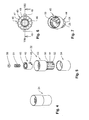
- Fig. 21 shows a cross section of in Fig. 20 illustrated handling device 120 with representation of engaging in the locking sleeve 113 of the transmission element 114 locking axle 112, wherein in the illustrated embodiment, the locking teeth 115 of the locking axle 112 in cross-section symmetrically formed locking teeth 121 which engage in the detent teeth 116 formed by locking grooves 116 of the transmission element 114. Due to the symmetrical configuration of the latching teeth 121, the latching engagement between the latching axis 112 and the latching sleeve 113 permits a relative rotation both in the clockwise direction and in the counterclockwise direction.
- a handling device 130 which, like the handling devices 22, 42, 70, 91 and 120 already described above, can be combined with the reservoir housing 21, wherein, in contrast to the already described handling devices 22, 42, 70, 91 and 120, the handling device 130 has an independently of a setting housing 131 formed guide member 132 which is formed as a guide housing and is connected via a formed at its upper end mounting ring 133 by means of a latching connection 134 rotatably connected to the reservoir housing 21.
- the guide member 132 is provided with guide slots 135, in each of which a guide pin 136 of a guide ring 137 formed as a pin arrangement is received axially guided.
- a locking connection 138 is formed at the lower end of the guide part 132 between the guide part 132 and an actuating housing 139 of an actuating device 162 that is rotatably mounted on the guide part 132.
- the actuating housing 139 has on its inner wall 140 a guide web 141, which has a defined pitch with a defined contact contour 142, such that during a relative rotation of the actuating housing 139 on the guide member 132, the guide pin 136 slide on the contact contour 142 and thereby in the guide slots 135 of the guide member 132 perform an axial movement, which is directed depending on the direction of rotation of the actuating housing 139 upwards or downwards, with the result that the guide ring 137 performs a corresponding upward or downward movement.
- a coil spring 148 is arranged, which is supported at one end to a bottom 145 of a guide member 132 received in the transmission element 146 and the other end on a pin 144 arranged on the stop 147 ,
- the coil spring 148 thus ensures that the transmission element 146 abuts against the guide ring 137, wherein a cup-shaped projection 149 of the transmission element 146 engages in an annular opening 150 of the guide ring 137 ( Fig. 25 ).
- the coil spring 148 ensures that, regardless of whether the guide ring 137 performs an upward movement or downward movement in the guide member 132, the guide pin 136 of the guide ring 137 defined on the contact contour 142 rest.
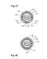
- FIG. 26 and 27 illustrates, in the handling device 130, an adjusting device 161, which serves for the defined adjustment or rotation of the transmission element 146 on the longitudinal axis 25 of the handling device 130, constructed of several parts and includes in addition to the here ring-shaped or sleeve-shaped adjusting housing 131 concentric with the adjusting housing 131 disposed within the guide member 132 adjusting sleeve 151.
- the adjusting sleeve 151 is provided with a radially outwardly projecting adjusting pin 152 which penetrates a guide member 132 formed in the adjusting groove 153 and by engaging in a formed on an inner wall 154 of the actuating housing 131 guide pocket 155 a rotationally fixed Connected to the adjusting housing 131 manufactures such that upon rotation of the adjusting housing 131 about the longitudinal axis 25 of the handling device 130, the adjusting sleeve 151 is forcibly rotated. In this case, the radial travel which the adjusting pin 152 performs, by limited radial stops 156, 157, which are defined by the adjusting groove 153. Furthermore, in particular, a synopsis of the Fig.
- the transmission element 146 is provided on its inner wall 158 with a contact surface 159 having contact portions 170 in a ring segment 160, which are arranged starting from a low-lying, central position defining central contact shoulder 170 along the circumference in both directions increasing.
- Fig. 25 shows, the transmission element 146 on its outer wall 172 driver projections 173 which engage in formed on an inner wall 174 of the adjusting sleeve 151 Mit Meetingn 175.
- the transmission element 146 within the adjusting sleeve 151 axially adjustable and rotatably relative to the longitudinal axis 25 of the handling device 130 is received in the adjusting sleeve 151, such that upon rotation of the outer actuating housing 131 about the longitudinal axis 25, the transmission element 146 a corresponding rotation about the longitudinal axis 25 executes.
- guide member 132 is between the adjusting sleeve 151 and the guide member 132 is an in Fig. 28 latching device 171 shown provided such that a formed on the outer wall of the adjusting sleeve 151 locking lug 176 with a plurality of circumferentially formed in the inner wall of the guide member 132 locking catches 178 cooperates, by overcoming a defined detent position determining rotational resistance between the adjusting sleeve 151 and the guide member 132 of a defined rotational position in which the detent 176 engages in a first latch 178, in a further defined rotational position in which the latch 176 engages in a different latch 178, can be changed.
Landscapes
- Engineering & Computer Science (AREA)
- Mechanical Engineering (AREA)
- Containers And Packaging Bodies Having A Special Means To Remove Contents (AREA)
- Infusion, Injection, And Reservoir Apparatuses (AREA)
- Coating Apparatus (AREA)
Description
- Die Erfindung betrifft einen Dosierspender zur dosierten Abgabe von zumindest zwei in jeweils einem Reservoir aufgenommenen Komponenten, wobei jedem Reservoir eine Fördereinrichtung zugeordnet ist und die Fördereinrichtungen mit einer Betätigungseinrichtung zur Ausgabe der Komponenten aus einer mit den Reservoirs verbundenen Ausgabeeinrichtung versehen sind, wobei die Betätigungseinrichtung mittelbar über eine Dosiereinrichtung auf die Fördereinrichtungen wirkt und die Dosiereinrichtung mit einer Stelleinrichtung versehen ist, mit deren Betätigung die Stellung eines auf die Fördereinrichtungen wirkenden Übertragungselements zur Einstellung des Mengenverhältnisses der Komponenten veränderbar ist.
- Aus der
EP 1 104 336 A1 ist ein Dosierspender der eingangs genannten Art bekannt, der eine Stelleinrichtung zur Einstellung des Mengenverhältnisses der Komponenten aufweist, die ein um eine Schwenkachse verschwenkbares Übertragungselement aufweist, das bei Ausführung einer Schwenkbewegung auf die Fördereinrichtungen wirkt. Zur Einstellung der Dosiereinrichtung wird mittels einer Stelleinrichtung die Schwenkachse des Übertragungselements um die Hochachse des Dosierspenders gedreht. Nach Einstellung der Dosiereinrichtung wird zur Ausgabe der Komponenten aus den Reservoirs auf einen Betätigungsabschnitt des Übertragungselements eine Betätigungskraft ausgeübt, derart, dass infolge der Einwirkung der Betätigungskraft das Übertragungselement um die quer zur Längsachse des Dosierspenders verlaufende Schwenkachse verschwenkt wird. - Aus der
DE 20 2009 014 316 U1 ist ebenfalls ein Dosierspender der eingangs genannten Art bekannt. - Die bei dem bekannten Dosierspender notwendige translatorische Betätigung zur Ausführung einer Schwenkbewegung des Übertragungselements um die quer zur Längsachse orientierte Schwenkachse des Übertragungselements erlaubt in der Praxis eine nur sehr ungenaue Dosierung der aus der Ausgabeeinrichtung ausgegebenen Gesamtmenge der beiden Komponenten. Die Ausgabe einer reproduzierbaren Ausgabemenge der beiden Komponenten ist mit der bekannten Betätigungseinrichtung nur möglich bei Ausführung eines vollständigen Ausschlags des Übertragungselements um die Schwenkachse. Dem hingegen ist die Ausgabe lediglich einer Teilmenge der möglichen Maximalmenge kaum reproduzierbar möglich, da die reproduzierbare Ausgabe einer Teilmenge eine entsprechend reproduzierbare Ausführung eines Teilausschlags des Übertragungselementes voraussetzt. Die Ausführung eines definierten Ausschlags des Betätigungselements ist jedoch bei dem insgesamt nur sehr geringen Weg, den das Übertragungselement bei einer Schwenkbewegung durchführt, kaum möglich.
- Der vorliegenden Erfindung liegt daher die Aufgabe zugrunde, einen Dosierspender vorzuschlagen, der eine genaue Dosierung einer aus zwei Komponenten zusammengesetzten Ausgabemenge ermöglicht.
- Darüber hinaus ist es eine Aufgabe der Erfindung, einen Dosierspender vorzuschlagen, der einfacher und somit für den Benutzer angenehmer zu betätigen ist.
- Zur Lösung dieser Ausgabe weist der erfindungsgemäße Dosierspender die Merkmale des Anspruchs 1 auf.
- Bei dem erfindungsgemäßen Dosierspender sind sowohl die Stelleinrichtungen zur Einstellung des Mengenverhältnisses der Komponenten als auch die Betätigungseinrichtung zur Ausgabe der Komponenten aus der Ausgabeeinrichtung zu ihrer Betätigung um eine Längsachse des Dosierspenders drehbar.
- Bei der Erfindung wird von der Erkenntnis Gebrauch gemacht, dass es grundsätzlich von dem Benutzer eines Dosierspenders als angenehmer empfunden wird, die Betätigungen oder Einstellungen, die von ihm an dem Dosierspender beim Gebrauch vorzunehmen sind, mittels gleichartiger händischer Bewegungen auszuführen. Dies insbesondere deswegen, da bei dem erfindungsgemäßen Dosierspender zwischen der Einstellung des Mischungsverhältnisses der Komponenten und der Betätigung zur Ausgabe der Komponenten in dem eingestellten Mischungsverhältnis keine Änderung in der Handhabung des Dosierspenders vorzunehmen ist. Vielmehr ist in beiden Fällen jeweils eine Drehbewegung um die Längsachse des Dosierspenders auszuführen.
- Darüber hinaus liegt der Erfindung die Erkenntnis zugrunde, dass es aus ergonomischen Gründen für den Benutzer eines Dosierspenders wesentlich einfacher ist, eine reproduzierbare Drehbewegung auszuführen, als dies bei einer translatorischen Bewegung der Fall ist, insbesondere dann, wenn der für die Auflösung der translatorischen Bewegung zur Verfügung stehende Stellweg eher kurz ist.
- Bei einer bevorzugten Ausführungsform des Dosierspenders weist die Stelleinrichtung der Dosiereinrichtung ein um die Längsachse eines Reservoirgehäuses, in dem die Reservoirs zur Aufnahme der Komponenten und die Fördereinrichtungen aufgenommen sind, ein drehbares Stellgehäuse auf, in dem das Übertragungselement gegenüber dem Stellgehäuse drehstarr und auf der Längsachse des Stellgehäuses zur Betätigung der Fördereinrichtungen axial verschiebbar angeordnet ist, wobei das Übertragungselement eine ringförmig oder als Ringsegment ausgebildete Kontaktoberfläche aufweist, mit einer sich umlaufend ändernden Oberflächenkontur, die mit den Fördereinrichtungen zusammenwirkt.
- Bei dieser vorteilhaften Ausführungsform ermöglicht demnach die besondere Ausgestaltung der Stelleinrichtung eine Umwandlung einer durch Einwirkung auf das Stellgehäuse von außen durch den Benutzer aufgebrachten manuellen Drehbewegung des Stellgehäuses in eine axiale oder translatorische Bewegung des Übertragungselements, sodass einerseits eine ergonomisch günstige Drehverstellung der Stelleinrichtung durch den Benutzer möglich ist, andererseits durch die axiale Stellbewegung des Übertragungselements eine funktionssichere Betätigung der Fördereinrichtungen möglich ist, bei der stets die horizontale Ausrichtung des Übertragungselements bezogen auf eine vertikale Ausrichtung der Längsachse des Dispensers erhalten bleibt.
- Insbesondere ergeben sich bei einer Beaufschlagung der Fördereinrichtungen durch das Übertragungselement keine Relativbewegungen zwischen dem Übertragungselement und den Fördereinrichtungen, die zu Abnutzungserscheinungen führen könnten, welche dem zuverlässigen und in gewünschter Weise lange währenden und sicheren Gebrauch des Dispensers entgegen stehen könnten.
- Die Einstellung des gewünschten Mengenverhältnisses zwischen den beiden für die Ausgabe vorgesehenen Komponenten erfolgt lediglich durch eine Drehung des Übertragungselements um die Hochachse des Dosierspenders bzw. des Stellgehäuses so weit, bis die Relativstellung des Übertragungselements gegenüber den Fördereinrichtungen erreicht ist, in der die das Mengenverhältnis definierenden unterschiedlichen Kontaktstellen des Übertragungselements den Fördereinrichtungen zugeordnet sind.
- Vorteilhafterweise kann die Betätigungseinrichtung zur Ausgabe der Komponenten ein um die Längsachse des Dosierspenders relativ zum Stellgehäuse drehbares Betätigungsgehäuse aufweisen, das mit einer Führungsanordnung zur axialen Verschiebbarkeit des Übertragungselementes versehen ist, wobei eine erste im Betätigungsgehäuse ausgebildeten Führungseinrichtung der Führungsanordnung zur Umwandlung einer Drehbewegung des Betätigungsgehäuses in eine axiale Bewegung des Übertragungselements mit einer zweiten unabhängig vom Betätigungsgehäuse ausgebildeten Führungseinrichtung der Führungsanordnung zusammenwirkt.
- Eine besonders betriebssichere und zugleich einfach ausführbare Ausgestaltung der zweiten Führungseinrichtung wird möglich, wenn die zweite Führungseinrichtung ein Führungsteil mit einer axial ausgerichteten Führungskulisse und eine am Übertragungselement positionierte Zapfenanordnung mit zumindest einem radialen Führungszapfen aufweist, der die Führungskulisse durchdringt und mit seinem Kontaktende mit der ersten Führungseinrichtung des Betätigungsgehäuses zusammenwirkt.
- Besonders vorteilhaft ist es auch, wenn das Betätigungsgehäuse zur Ausbildung der ersten Führungseinrichtung auf seiner koaxial zum Führungsteil des Stellgehäuses angeordneten Innenwandung eine Führungsbahn mit einer mit dem Kontaktende des Führungszapfens zusammenwirkenden Kontaktkontur aufweist, die die axiale Bewegung des Übertragungselements steuert, sodass aufgrund der koaxialen Anordnung des Betätigungsgehäuses zum Stellgehäuse eine insgesamt kompakte Ausgestaltung des Dispensers möglich wird.
- Eine Drehrichtungssperre oder Definition einer möglich Drehrichtung kann erreicht werden, wenn die im Führungsteil ausgebildete, axial ausgerichtete Führungskulisse an ihrem unteren Ende zur Definition einer Drehrichtung der Betätigungseinrichtung eine Zapfenfalle zur Aufnahme des radialen Führungszapfens aufweist.
- Eine besonders vorteilhafte Ausgestaltung des Dosierspenders, die zu einer weiteren Erhöhung der Reproduzierbarkeit definierter Ausgabemengen des Dispensers beiträgt, weist zur Definition einer Ausgangsstellung der Betätigungseinrichtung, in der die Fördereinrichtungen nicht durch das Übertragungselement beaufschlagt werden, zwischen einem am Führungsteil ausgebildeten Anschlag und dem Übertragungselement eine Federeinrichtung auf, sodass die Ausgangsstellung für den Benutzer dadurch haptisch genau erfassbar ist, dass in der Ausgangsstellung ein Widerstand gegen die Drehverstellung der Betätigungseinrichtung minimiert ist.
- Besonders vorteilhaft ist es, wenn der Anschlag am axialen Ende eines am Boden des Führungsteils angeordneten Zapfens ausgebildet ist, der sich durch eine in einem Boden einer zentralen hülsenförmigen Vertiefung des Übertragungselements ausgebildete Öffnung erstreckt, und wenn die Federeinrichtung als eine Schraubenfeder ausgebildet ist, die in einem zwischen dem Zapfen und der Vertiefung ausgebildeten Ringraum angeordnet ist und sich zwischen dem Anschlag und dem Boden erstreckt. Hierdurch ist eine sichere Gehäusung für die Federeinrichtung geschaffen, sodass die Funktion der Federeinrichtung auch bei einem lange währenden Gebrauch des Dosierspenders sichergestellt ist.
- Alternativ zur Ausgestaltung des Dosierspenders mit einer Federeinrichtung besteht auch die vorteilhafte Möglichkeit, zur Definition einer Ausgangsstellung der Betätigungseinrichtung, an einem axialen Ende eines im Führungsteil angeordneten Rastzapfens eine Rasteinrichtung vorzusehen, die bei dem in Ausgangsstellung befindlichen Übertragungselement einen Rand einer zentralen Öffnung im Übertragungselement hintergreift.
- Bei dieser Ausführungsform des Dosierspenders, bei der die konstruktiven Maßnahmen zur Definition der Ausgangsstellung der Betätigungseinrichtung in besonders einfacher Art und Weise ausgeführt sind, erweist es sich zur betriebssicheren Funktion als vorteilhaft, wenn die in der Innenwandung des Betätigungsgehäuses angeordnete Führungsbahn als Führungsnut ausgebildet ist, deren parallel zueinander verlaufende Nutränder den Führungszapfen zwischen sich aufnehmen.
- Besonders vorteilhaft ist es auch, wenn zur Ausbildung der zweiten Führungseinrichtung das Führungsteil durch das Stellgehäuse ausgebildet ist, und die Zapfenanordnung mit dem zumindest einen Führungszapfen am Übertragungselement ausgebildet ist, derart, dass bei einer Drehung des Stellgehäuses eine entsprechende Drehung des Führungsteils erfolgt. Hierdurch kommt dem Stellgehäuse eine vorteilhafte Doppelfunktion zu, so dass eine entsprechende Reduktion der Menge an Einzelteile möglich wird.
- Bei einer besonders vorteilhaften Ausführungsform des Dosierspenders ist zur definierten Relativanordnung des Stellgehäuses zum Reservoirgehäuse eine Rasteinrichtung zwischen dem Stellgehäuse und dem Reservoirgehäuse ausgebildet, die eine Mehrzahl von Raststellungen für eine definierte Zuordnung von auf der Kontaktoberfläche ausgebildeten Kontaktstellen des Übertragungselements und auf Förderkolben der Fördereinrichtungen wirkenden Stößeln aufweist. Zum einen erleichtert die Rasteinrichtung das wiederholte Auffinden einer relativen Drehstellung zwischen dem Stellgehäuse und dem Reservoirgehäuse zur reproduzierbaren Einstellung eines Mischungsverhältnisses. Zum anderen kann die Einstellung eines einmal eingestellten Mischungsverhältnisses zwischen den Komponenten durch die Rasteinrichtung gesichert werden.
- Wenn die Rasteinrichtung als eine modulare, zwischen das Reservoirgehäuse und das Stellgehäuse einsetzbare Rasteinheit ausgebildet ist, die drehrichtungsabhängig zur Relativdrehung des Stellgehäuses gegenüber dem Reservoirgehäuse betätigbar ist, kann durch einen einfachen Austausch der Rasteinrichtung die Drehrichtung eingestellt werden.
- Besonders vorteilhaft ist es, wenn die Rasteinheit ein erstes, drehfest mit dem Reservoirgehäuse verbindbares, ringförmiges Rastelement und ein zweites, drehfest mit dem Stellgehäuse verbindbares, ringförmiges Rastelement aufweist, wobei die Rastelemente über einen in einer gemeinsamen Ringebene ausgebildeten, durch Rastvorsprünge hergestellten Rasteingriff zusammenwirken, und die Rastvorsprünge durch eine Sperrklinken-Verzahnung ausgebildet sind, so die Rasteinheit mit geringem Materialeinsatz und sehr platzsparend ausführbar ist.
- Ein elastisch nachgiebiger Rasteingriff wird möglich, wenn eines der beiden Rastelemente die Sperrklinken-Verzahnung lediglich in einem Ringsegment aufweist.
- Eine besonders exakte Relativausrichtung zwischen dem Reservoirgehäuse und dem Stellgehäuse wird möglich, wenn die Rasteinrichtung eine mit dem Reservoirgehäuse verbundene Rastachse aufweist, die zur Ausbildung eines Rasteingriffs in eine als Rasthülse ausgebildete Nabe des Übertragungselements eingreift.
- Zur Ausbildung des Rasteingriffs ist es vorteilhaft, wenn auf dem Umfang der Rastachse ausgebildete Rastvorsprünge mit auf der Bohrungswandung der Hülse ausgebildeten Rastvorsprüngen zusammenwirken.
- Eine besonders betriebssicher Ausgestaltung wird möglich, wenn die Rastvorsprünge durch eine Sperrklinken-Verzahnung ausgebildet sind.
- Bei einer vorteilhaften Vatiante zur Ausbildung der zweiten Führungseinrichtung ist das Führungsteil drehfest mit dem Reservoirgehäuse verbunden, und die Zapfenanordnung ist als Führungsring mit zumindest einem Führungszapfen ausgebildet ist. Darüber hinaus ist das Übertragungselement im Führungsring drehbar aufgenommen und mittels einer radialen Eingriffseinrichtung drehfest mit dem Stellgehäuse verbunden, derart, dass bei einer Drehung des Stellgehäuses dieses eine Relativdrehung gegenüber dem Führungsgehäuse ausführt. Auf diese Art und Weise kann verhindert werden, dass bei einer Beaufschlagung der Stößel der Fördereinrichtungen die Stößel durch ein Drehmoment beansprucht werden.
- Wenn die Eingriffseinrichtung eine Stellhülse aufweist, in der das Übertragungselement drehfest und axial verschiebbar aufgenommen ist, wobei die Stellhülse über einen Stellzapfen, der das Führungsteil in einer Stellnut radial durchdringt, eine Eingriffsverbindung mit dem Stellgehäuse ausbildet, kann das Stellgehäuse als Stellring ausgebildet werden.
- Wenn zur definierten Relativanordnung des Stellgehäuses eine Rasteinrichtung zwischen der Stellhülse und dem Führungsteil ausgebildet ist, die eine Mehrzahl von Raststellungen für eine definierte Zuordnung von auf der Kontaktoberfläche ausgebildeten Kontaktstellen des Übertragungselements und auf Förderkolben der Fördereinrichtungen wirkenden Stößeln aufweist, kann trotz einer möglichen einfachen Ausgestaltung des Stellgehäuses als Ring eine reproduzierbare Einstellung ermöglicht werden.
- Wenn gemäß einer besonders vorteilhaften Ausführungsform die Kontaktstellen auf der Kontaktoberfläche des Übertragungselements durch in einer Stufenfolge angeordnete Kontaktabsätze gebildet sind, ist sichergestellt, dass trotz einer sich über den Umfang des Übertragungselements ändernden Oberflächenkontur bzw. Topografie unabhängig von der Relativstellung des Übertragungselements zu den Stößeln der Fördereinrichtungen stets übereinstimmende Kontaktverhältnisse zwischen dem Übertragungselement und dem Stößel ausgebildet sind.
- Wenn darüber hinaus die Kontaktabsätze durch Sackbohrungen ausgebildet sind, die in einer horizontalen Oberfläche des Übertragungselements angeordnet sind, ist eine besonders formgenaue Anpassung zwischen den Kontaktstellen und den Stößeln der Fördereinrichtungen möglich, womit einem ansonsten möglichen Verschleiß entgegengewirkt wird. Vorteilhafte Ausführungsformen des Dosierspenders werden nachfolgend anhand der Zeichnungen näher erläutert.
- Es zeigen:
- Fig. 1:
- Eine Ausführungsform eines Dosierspenders mit einem Reservoirgehäuse mit Handhabungseinrichtung;
- Fig. 2:
- den in
Fig. 1 dargestellten Dosierspender in einer Schnittdarstellung gemäß Schnittlinienverlauf II-II inFig. 1 ; - Fig. 3:
- eine Schnittdarstellung gemäß Schnittlinienverlauf III-III in
Fig. 2 ; - Fig. 4:
- die aus einer Stelleinrichtung und einer Betätigungseinrichtung gebildete Handhabungseinrichtung des in
Fig. 1 dargestellten Dosierspenders; - Fig. 5:
- eine Explosionsdarstellung der in
Fig. 4 dargestellten Handhabungseinrichtung; - Fig. 6:
- ein Übertragungselement der in
Fig. 5 dargestellten Handhabungseinrichtung in Draufsicht; - Fig. 7:
- eine isometrische Darstellung eines in
Fig. 5 dargestellten Stellgehäuses; - Fig. 8:
- eine Schnittdarstellung des in
Fig. 6 dargestellten Übertragungselements gemäß Schnittlinienverlauf VIII-VIII inFig. 6 ; - Fig. 9:
- eine Draufsicht auf das in das Stellgehäuse eingesetzte Übertragungselement;
- Fig. 10:
- eine Schnittdarstellung der in
Fig. 4 dargestellten Handhabungseinrichtung mit einem in Ausgangsstellung angeordneten Übertragungselement; - Fig. 11:
- eine Schnittdarstellung der in
Fig. 10 dargestellten Handhabungseinrichtung gemäß Schnittlinienverlauf XI-XI inFig. 10 ; - Fig. 12:
- eine Schnittdarstellung der in
Fig. 10 dargestellten Handhabungseinrichtung gemäß Schnittlinienverlauf XII-XII inFig. 10 ; - Fig. 13:
- eine Einzeldarstellung eines gemäß der Darstellung in
Fig. 11 mit einem Führungsteil des Stellgehäuses koaxial verbundenen Betätigungsgehäuses; - Fig. 14:
- eine weitere Ausführungsform der Handhabungseinrichtung in einer
Fig. 12 entsprechenden Darstellung; - Fig. 15:
- ein Betätigungsgehäuse zur Kombination mit dem in
Fig. 14 dargestellten Stellgehäuse der Handhabungseinrichtung; - Fig. 16:
- eine weitere Ausführungsform eines Dosierspenders in Längsschnittdarstellung;
- Fig. 17:
- eine Explosionsdarstellung der Handhabungseinrichtung des in
Fig. 16 dargestellten Dosierspenders; - Fig. 18:
- eine weitere Ausführungsform eines Dosierspenders in Längsschnittdarstellung;
- Fig. 19:
- eine Explosionsdarstellung der Handhabungseinrichtung des in
Fig. 18 dargestellten Dosierspenders; - Fig. 20:
- eine Längsschnittdarstellung der in
Fig. 19 dargestellten Handhabungseinrichtung; - Fig. 21:
- eine Schnittdarstellung der in
Fig. 20 dargestellten Handhabungseinrichtung; - Fig. 22:
- eine weitere Ausführungsform einer Handhabungseinrichtung in Längsschnittdarstellung;
- Fig. 23:
- eine Schnittdarstellung der in
Fig. 22 dargestellten Handhabungseinrichtung; - Fig. 24:
- eine isometrische Darstellung einer weiteren Handhabungseinrichtung;
- Fig. 25:
- eine Explosionsdarstellung der in
Fig. 24 dargestellten Handhabungseinrichtung; - Fig. 26:
- eine Schnittdarstellung der in
Fig. 24 dargestellten Handhabungseinrichtung; - Fig. 27:
- eine Schnittdarstellung der in
Fig. 26 dargestellten Handhabungseinrichtung gemäß Schnittlinienverlauf XXVII - XXVII; - Fig. 28:
- eine Schnittdarstellung der in
Fig. 26 dargestellten Handhabungseinrichtung gemäß Schnittlinienverlauf XXVIII-XXVIII. - In den
Fig. 1, 2 und 3 ist in einer Gesamtdarstellung ein Dosierspender 20 gezeigt, der als wesentliche Bestandteile eine mit einem Reservoirgehäuse 21 verbundene Handhabungseinrichtung 22 aufweist, die eine Einstelleinrichtung 23 mit einer Betätigungseinrichtung 24 kombiniert, wobei die Stelleinrichtung 23 und die Betätigungseinrichtung 24 jeweils relativ zueinander und gegenüber dem Reservoirgehäuse 21 um eine Längsachse 25 des Dosierspenders 20 drehbar mit dem Reservoirgehäuse 21 verbunden sind. - Wie insbesondere die
Fig. 2 und 3 zeigen, dient das Reservoirgehäuse 21 im Wesentlichen zur Aufnahme zweier Reservoirs 26 und 27, welche im vorliegenden Fall patronenförmig ausgebildet sind und jeweils eine Komponente eines viskosen Stoffs enthalten, bei dem es sich im Falle des hier dargestellten Ausführungsbeispiels des Dosierspenders um einen mit Pigmenten versetzten Lippenpflegestoff handelt, der mittels einer hier oberhalb der Reservoirs 26, 27 im Reservoirgehäuse 21 angeordneten und jeweils einem Reservoir zugeordneten Ventileinrichtung 28 bzw. 29 einer Mischeinrichtung 30 zugeleitet und schließlich aus dieser über eine gemeinsame Ausgabeeinrichtung 31 auf eine Applikatoroberfläche 32 aufgebracht wird, von der die miteinander vermischten Komponenten im Fall des vorliegend als Lippencremeapplikator ausgebildeten Dosierspenders 20 auf die Lippen des Benutzers übertragen werden können. Zur Abdeckung der Applikatoroberfläche 32 bei Nicht-Benutzung des Dosierspenders 20 ist das Reservoirgehäuse 21 mit einer Applikatorkappe 33 versehen. - Wie insbesondere
Fig. 2 zeigt, befinden sich am unteren Ende der Reservoirs 26, 27 Fördereinrichtungen 34, 35, die jeweils unmittelbar Druck auf die in den Reservoirs 26, 27 aufgenommenen Komponenten mittels Förderkolben 36, 37 ausüben, welche über jeweils einen Stößel 38, 39 von einem Übertragungselement 40 beaufschlagt werden, das Bestandteil der Stelleinrichtung 23 der Handhabungseinrichtung 22 ist. - Die in
Fig. 2 und denFig. 4 und 5 dargestellte Handhabungseinrichtung 22 ist über eine inFig. 2 dargestellte Rastverbindung 41 mit dem Reservoirgehäuse 21 verbunden. Die Stelleinrichtung 23 weist ein Stellgehäuse 43 auf, dessen unterer Teil als Führungsteil 44 zur Aufnahme des Übertragungselements 40 ausgebildet ist. Das Übertragungsteil 40 ist im vorliegenden Fall hülsenartig ausgebildet mit in einer am oberen axialen Ende des Übertragungsteils ringförmig ausgebildeten Kontaktoberfläche 45, die mit einer ringförmig angelegten Reihung von Kontaktabsätzen 46 versehen ist (Fig. 6 ), die im vorliegenden Fall durch Böden 47 von in die Kontaktoberfläche 45 eingebrachten Sackbohrungen 48 ausgebildet sind. An seiner Außenwand weist das Übertragungselement 40 zwei diametral zueinander angeordnete Führungszapfen 49 auf, die jeweils in einer als Langloch im Führungsteil 44 des Stellgehäuses 43 ausgebildeten Führungskulisse 50 axial geführt sind. - Wie aus einer Zusammenschau der
Fig. 5, 7 und10 hervorgeht, weist das Führungsteil 44 des Stellgehäuses 43 an seinem unteren Ende benachbart einem Boden 51 einen Rastrand 52 auf, der einen auf einer Innenwandung 53 eines Betätigungsgehäuses 54 der Betätigungseinrichtung 24 ausgebildeten Raststeg 55 zur Herstellung einer Rastverbindung 56 zwischen dem Betätigungsgehäuse 54 und dem Stellgehäuse 43 hintergreift. - In der insbesondere in
Fig. 10 und 11 dargestellten, verrasteten Stellung zwischen dem Betätigungsgehäuse 54 und dem Stellgehäuse 43 ist das Übertragungselement 40 mit einer zentralen Lagerhülse 57 auf einem am Boden 51 ausgebildeten Zapfen 58 geführt. Der Zapfen 58 ist im Falle des inFig. 10 dargestellten Ausführungsbeispiels an seinem oberen Ende mit einem, hier als axialer Sicherungsring ausgebildeten Anschlag 59 versehen, der gegenüberliegend einem Boden 60 der Lagerhülse 57 angeordnet ist und zusammen mit diesem jeweils eine axiale Abstützung einer auf dem Zapfen 58 angeordneten Schraubenfeder 61 bildet. Die inFig. 10 dargestellte Ausführung ermöglicht daher eine axiale Verschiebung des Übertragungselements 40 auf dem Zapfen 58 entgegen der durch die Schraubenfeder 61 dabei erzeugten Druckkraft. Bei dieser axialen Verschiebung wird das Übertragungselement 40 mit den Führungszapfen 49 in den Führungskulissen 50 des Führungsteils 44 des Stellgehäuses 43 geführt. - Wie ein Vergleich der
Fig. 10 und12 zeigt, die die Handhabungseinrichtung 22 in unterschiedlichen Schnittansichten zeigen, weisen die in der Kontaktoberfläche 45 des Übertragungselements 40 zur Ausbildung der Kontaktabsätze 46 angeordneten Sackbohrungen 48 unterschiedliche Tiefen auf, so dass die durch die Böden 47 der Sackbohrungen 48 gebildeten Kontaktabsätze 46 unterschiedliche Niveaus bezogen auf eine mittlere Kontaktebene 62 aufweisen. Abweichend hiervon zeigtFig. 12 diametral einander gegenüberliegende Kontaktabsätze 46 mit einem gegenüber der mittleren Kontaktflächenebene 62 abweichenden Niveau, so dass bei einer axialen Verstellung des Übertragungselements 40 entgegen der Wirkung der Schraubenfeder 61 bei einem Kontakt der Stößel 38, 39 mit den Kontaktabsätzen 46 die Stößel 38, 39 unterschiedlich weit axial ausgelenkt werden, mit der Folge, dass auch die Förderkolben 36, 37 der Fördereinrichtungen 34, 35 einen unterschiedlichen Hub ausführen. - In den
Fig. 10 und12 ist das Übertragungselement 40 in voneinander abweichenden Schnittdarstellungen der Handhabungseinrichtung 22 in seiner Ausgangslage dargestellt, in der die Schraubenfeder 61 ihre maximal mögliche Entspannung aufweist und die Führungszapfen 49 am unteren Anschlag der Führungskulissen 50 anliegen. Zur axialen Verstellung des Übertragungselements 40 im Führungsteil 44 ist das Betätigungsgehäuse 54 der Betätigungseinrichtung 24 auf seiner Innenwandung mit einer insbesondere inFig. 13 dargestellten Führungsbahn versehen, die hier als ein Führungssteg 63 ausgebildet ist, dessen Kontaktkontur 64 gegen die Führungszapfen 49 des Übertragungselements 40 anliegt (Fig. 10 ), so dass bei einer Relativbewegung des Betätigungsgehäuses 54 der Betätigungseinrichtung 24 um die Achse 25 gegenüber dem Stellgehäuse 43 der Stelleinrichtung 23 eine dem Verlauf der Kontaktkontur 64 entsprechende axiale Bewegung des Übertragungselements 40 erfolgt. - Die Kontaktkontur 64 des Führungsstegs 63 weist eine die Ausgangslage des Übertragungselements 40 definierende Vertiefung 65 auf, derart, dass entsprechend der in
Fig. 13 dargestellten Kontaktkontur 64 bei einer Relativbewegung des Betätigungsgehäuses 54 um die Längsachse 25 im Uhrzeigersinn das Übertragungselement 40 entlang einer Aufwärtsrampe 66 axial nach oben bewegt wird. Nach Erreichen eines inFig. 13 strichpunktiert angedeuteten Rampenscheitelpunkts 67 bewegt sich dann in Folge der Vorspannkraft der Schraubenfeder 61 das Übertragungsteil 40 entlang einer Abwärtsrampe 68 wieder in eine zweite, der ersten Vertiefung 65 diametral gegenüberliegende Vertiefung 69, wobei dann das Betätigungsgehäuse 54 eine Drehung von 180° um die Längsachse 25 ausgeführt hat. - Bei der vorstehend beschriebenen axialen Vorschubbewegung des Übertragungselements 40 im Stellgehäuse 43 der Stelleinrichtung 23 befindet sich das Stellgehäuse 43 gegenüber dem Reservoirgehäuse 21 in definierter Relativanordnung, so dass sich auch die Drehstellung des Übertragungselements 40 gegenüber den Stößeln 38, 39 nicht verändert.
- Wie bereits vorstehend Bezug nehmend auf
Fig. 10 ausgeführt, bewirkt die inFig. 2 dargestellte Drehstellung des Übertragungselements, bei der die einander diametral gegenüberliegenden Kontaktabsätze 46 ein übereinstimmendes Niveau aufweisen, eine entsprechend übereinstimmende axiale Verschiebung der Stößel 38, 39. Demzufolge werden durch die Fördereinrichtungen 34, 35 jeweils übereinstimmende Mengen aus den Reservoirs 26, 27 in die Mischeinrichtung 30 und von dieser durch die Ausgabeeinrichtung 31 auf die Applikatoroberfläche 32 gefördert. Zur Einstellung eines hiervon abweichenden Mischungsverhältnisses zwischen den in den Reservoirs 26, 27 aufgenommenen Komponenten kann nun das Stellgehäuse 43 der Stelleinrichtung 23 zusammen mit dem daran angeordneten Betätigungsgehäuse 54 der Betätigungseinrichtung 24 um die Längsachse 25 verdreht werden, bis den Stößeln 38, 39 axial fluchtend Kontaktabsätze 46 zugeordnet sind, die ein voneinander abweichendes Niveau, wie beispielsweise inFig. 12 dargestellt, aufweisen, so dass bei einer Kontaktierung dieser Kontaktabsätze 46 in Folge einer nachfolgenden Vorschubbewegung des Übertragungselements gegen die Stößel 38, 39 bei weiterer Drehung des Betätigungsgehäuses 54 gegenüber dem Stellgehäuse 43 die Stößel 38, 39 entsprechend unterschiedlich ausgelenkt werden, mit der weiteren Folge, dass entsprechend unterschiedliche Mengen der Komponenten aus den Reservoirs 26, 27 in die Mischeinrichtung 30 gefördert und auf die Applikatoroberfläche 32 ausgegeben werden. - In den
Fig. 14 und 15 ist in einer weiteren Ausführungsform eine Handhabungseinrichtung 70 dargestellt, die eine Stelleinrichtung 71 und eine Betätigungseinrichtung 72 umfasst, welche ein Stellgehäuse 73 bzw. ein Betätigungsgehäuse 74 aufweisen sowie ein Übertragungselement 75, die im Vergleich zu dem Stellgehäuse 43, dem Betätigungsgehäuse 54 und dem Übertragungselement 40 der insbesondere in denFig. 10 und12 dargestellten Handhabungseinrichtung 22 Änderungen aufweisen, die nachstehend erläutert werden sollen. - Zur Definition einer Ausgangsstellung der Betätigungseinrichtung 72 ist in einem Führungsteil 76 des Stellgehäuses 73 ein am Boden 77 angeordneter Rastzapfen 78 vorgesehen, der an seinem axialen Ende eine durch federnd ausgebildete Rastnasen 79 gebildete Rasteinrichtung 80 aufweist, die einen Öffnungsrand 81 einer zentralen Öffnung 82 im Übertragungselement 75 hintergreift.
- Zur Führung von in der Ansicht gemäß
Fig. 14 nicht näher dargestellten, jedoch mit den Führungszapfen 49 des Übertragungselements 40 übereinstimmenden Führungszapfen ist in einer Innenwandung 83 des Betätigungsgehäuses 74 eine Führungsbahn als Führungsnut 85 ausgebildet mit parallel zueinander verlaufenden Nuträndern 86, 87, die die Führungszapfen zwischen sich aufnehmen und so sowohl bei einer Aufwärtsbewegung als auch bei einer Abwärtsbewegung des Übertragungselements 75 für einen sicheren Kraftschluss zwischen der durch die Führungsnut 85 gebildeten Führungseinrichtung des Betätigungsgehäuses 74 und dem Übertragungselement 75 sorgen. -
Fig. 16 zeigt einen Dosierspender 88, der analog dem in denFig. 1 bis 3 dargestellten Dosierspender 20 mit einem Reservoirgehäuse 21 versehen ist, das mit einer Stelleinrichtung 89 und einer Betätigungseinrichtung 90 versehen ist, die eine Handhabungseinrichtung 91 ausbilden und auf einer gemeinsamen Längsachse 25 mit dem Reservoirgehäuse 21 angeordnet sind. - Die Handhabungseinrichtung 91 ist in
Fig. 17 in einer Explosionsdarstellung gezeigt und umfasst ein Stellgehäuse 92 der Stelleinrichtung 89 sowie ein Betätigungsgehäuse 93 der Betätigungseinrichtung 90. Ein Vergleich mit der inFig. 5 dargestellten Handhabungseinrichtung 22 des Dosierspenders 20 zeigt, dass das Stellgehäuse 92 mit einem Führungsteil 94 versehen ist, der im Unterschied zu dem Führungsteil 44 des Stellgehäuses 43 mit einer Führungskulisse 95 versehen ist, die an ihrem unteren Ende eine hier als Ausnehmung ausgebildete Zapfenfalle 96 aufweist. Die Zapfenfalle 96 wirkt mit dem in der Führungskulisse 95 geführten Führungszapfen 49 des Übertragungselements 40 derart zusammen, dass bei einer Drehung des Betätigungsgehäuses 93 der Betätigungseinrichtung 90 im Uhrzeigersinn das Übertragungselement 40 durch den Führungssteg 63 auf der Längsachse 25 nach oben bewegt wird. Bei einer Drehung des Betätigungsgehäuses 93 entgegen dem Uhrzeigersinn wird jedoch eine translatorische Aufwärtsbewegung des Übertragungselements 40 auf der Längsachse 25 dadurch blockiert, dass der Führungszapfen 49 in der Zapfenfalle 96 gehalten wird. Die derart ausgebildete Führungskulisse 95 des Stellgehäuses 92 definiert somit eine Betätigungs- bzw. Drehrichtung für die Betätigungseinrichtung 90. - Als weiterer Unterschied zu der Handhabungseinrichtung 22 des Dosierspenders 20 weist die Handhabungseinrichtung 91 des Dosierspenders 88 eine modular ausgebildete Rasteinrichtung 97 auf, die zwei voneinander unabhängig ausgebildete ringförmige Rastelemente 98, 99 aufweist, welche zwischen dem Reservoirgehäuse 21 und dem Stellgehäuse 92 derart angeordnet sind, dass das Rastelement 98 über Oberflächenausnehmungen 100, 101, in die Fortsätze 102 , 103 des Reservoirgehäuses 21 eingreifen, drehfest mit dem Reservoirgehäuse 21 verbunden ist. Das Rastelement 99 weist Klinkenfortsätze 104, 105 auf, über die das Rastelement 99 drehfest mit dem Stellgehäuse 92 verbunden ist. Zwischen dem Rastelement 98 und dem Rastelement 99 ist ein Rasteingriff hergestellt durch eine jeweils am Rastelement 98 sowie am Rastelement 99 ausgebildete Sperrklinken-Verzahnung 106, 107, die eine Relativdrehung der Rastelemente 98, 99 bei der in
Fig. 17 dargestellten Ausführungsform mit geneigten Zahnflanken 108 nur entgegen dem Uhrzeigersinn ermöglicht, so dass bei der in denFig. 16 und 17 dargestellten Ausführungsform des Dosierspenders 88 die Betätigungseinrichtung 90 im Uhrzeigersinn und die Stelleinrichtung 89 entgegen dem Uhrzeigersinn betätigt werden können. - In den
Fig. 18 und 19 ist in einer weiteren Ausführungsform ein Dosierspender 110 mit einer Handhabungseinrichtung 120 dargestellt, der im Unterschied zu dem vorstehend erläuterten Dosierspender 88 eine Rasteinrichtung 111 aufweist, die eine mit dem Reservoirgehäuse 21 drehfest verbundene Rastachse 112 aufweist, welche in eine als Rasthülse 113 ausgebildete Nabe eines Übertragungselements 114 eingreift und dabei einen Rasteingriff zwischen einer auf dem Außenumfang der Rastachse 112 ausgebildeten Rastverzahnung 115 und einer auf der Bohrungswandung der Rasthülse 113 ausgebildeten Rastverzahnung 116 ausbildet. Die Rastachse 112 ist mit einer tellerförmigen Achsenbasis 117 versehen, die an ihrem oberen Rand Vorsprünge 118, 119 zum Eingriff in nicht näher dargestellte, am unteren Rand des Reservoirgehäuses 21 ausgebildete Ausnehmungen aufweist und eine drehfeste Verbindung zum Reservoirgehäuse 21 herstellt. -
Fig. 21 zeigt einen Querschnitt der inFig. 20 dargestellten Handhabungseinrichtung 120 mit Darstellung der in die Rasthülse 113 des Übertragungselements 114 eingreifenden Rastachse 112, wobei in dem dargestellten Ausführungsbeispiel die Rastverzahnung 115 der Rastachse 112 im Querschnitt symmetrisch ausgebildete Rastzähne 121 aufweist, die in die durch Rastnuten 122 ausgebildete Rastverzahnung 116 des Übertragungselements 114 eingreifen. Aufgrund der symmetrischen Ausgestaltung der Rastzähne 121 ermöglicht der Rasteingriff zwischen der Rastachse 112 und der Rasthülse 113 eine Relativdrehung sowohl im Uhrzeigersinn als auch entgegen dem Uhrzeigersinn. - Im Vergleich dazu weist eine in
Fig. 23 dargestellte Rastachse 123 eine Rastverzahnung 124 mit Rastzähnen 125 auf, die sperrklinkenartig ausgebildet sind mit geneigten Zahnflanken 126, die durch die Rastnuten 122 der Rastverzahnung 116 des Übertragungselements 1 14 eine Relativdrehung zwischen dem Stellgehäuse 43 (Fig. 19 ) und dem Reservoirgehäuse 21 (sieheFig. 18 ) lediglich entgegen dem Uhrzeigersinn ermöglichen. - In den
Fig. 24 bis 26 ist in einer weiteren Ausführungsform eine Handhabungseinrichtung 130 dargestellt, die, wie die vorstehend bereits beschriebenen Handhabungseinrichtungen 22, 42, 70, 91 und 120 mit dem Reservoirgehäuse 21 kombinierbar ist, wobei im Unterschied zu den bereits beschriebenen Handhabungseinrichtungen 22, 42, 70, 91 und 120 die Handhabungseinrichtung 130 ein unabhängig von einem Stellgehäuse 131 ausgebildetes Führungsteil 132 aufweist, das als Führungsgehäuse ausgebildet ist und über einen an seinem oberen Ende ausgebildeten Befestigungsring 133 mittels einer Rastverbindung 134 drehfest mit dem Reservoirgehäuse 21 verbunden ist. - Wie insbesondere eine Zusammenschau der
Fig. 25 und 26 deutlich macht, ist das Führungsteil 132 mit Führungskulissen 135 versehen, in denen jeweils ein Führungszapfen 136 einer als Führungsring 137 ausgebildeten Zapfenanordnung axial geführt aufgenommen wird. - Weiterhin zeigt insbesondere die
Fig. 25 , dass am unteren Ende des Führungsteils 132 eine Rastverbindung 138 zwischen dem Führungsteil 132 und einem auf dem Führungsteil 132 drehbar angeordneten Betätigungsgehäuse 139 einer Betätigungseinrichtung 162 ausgebildet ist. Das Betätigungsgehäuse 139 weist auf seiner Innenwandung 140 einen Führungssteg 141 auf, der eine mit definierter Steigung ausgebildete Kontaktkontur 142 aufweist, derart, dass bei einer Relativdrehung des Betätigungsgehäuses 139 auf dem Führungsteil 132 die Führungszapfen 136 auf der Kontaktkontur 142 entlang gleiten und dabei in den Führungskulissen 135 des Führungsteils 132 eine axiale Bewegung ausführen, die je nach Drehrichtung des Betätigungsgehäuses 139 aufwärts oder abwärts gerichtet ist, mit der Folge, dass der Führungsring 137 eine entsprechende Aufwärts- oder Abwärtsbewegung ausführt. - Auf einem an einem Boden 143 des Führungsteils 132 ausgebildeten Zapfen 144, ist eine Schraubenfeder 148 angeordnet, die sich mit einem Ende an einen Boden 145 eines im Führungsteil 132 aufgenommenen Übertragungselementes 146 und mit dem anderen Ende an einem auf dem Zapfen 144 angeordneten Anschlag 147 abstützt. Die Schraubenfeder 148 sorgt somit dafür, dass das Übertragungselement 146 gegen den Führungsring 137 anliegt, wobei ein becherförmiger Vorsprung 149 des Übertragungselements 146 in eine Ringöffnung 150 des Führungsrings 137 eingreift (
Fig. 25 ). Gleichzeitig sorgt die Schraubenfeder 148 dafür, dass, unabhängig davon, ob der Führungsring 137 eine Aufwärtsbewegung oder Abwärtsbewegung im Führungsteil 132 ausführt, die Führungszapfen 136 des Führungsrings 137 definiert auf der Kontaktkontur 142 aufliegen. - Wie insbesondere eine Zusammenschau der
Fig. 26 und27 verdeutlicht, ist bei der Handhabungseinrichtung 130 eine Stelleinrichtung 161, die zur definierten Verstellung bzw. Verdrehung des Übertragungselements 146 auf der Längsachse 25 der Handhabungseinrichtung 130 dient, aus mehreren Teilen aufgebaut und umfasst neben dem hier ring- oder hülsenförmig ausgebildeten Stellgehäuse 131 eine konzentrisch zum Stellgehäuse 131 innerhalb des Führungsteils 132 angeordnete Stellhülse 151. Die Stellhülse 151 ist mit einem radial nach außen ragenden Stellzapfen 152 versehen, der eine im Führungsteil 132 ausgebildete Stellnut 153 durchdringt und durch einen Eingriff in eine auf eine Innenwandung 154 des Stellgehäuses 131 ausgebildete Führungstasche 155 eine drehfeste Verbindung mit dem Stellgehäuse 131 herstellt, derart, dass bei einer Drehung des Stellgehäuses 131 um die Längsachse 25 der Handhabungseinrichtung 130 die Stellhülse 151 zwangsweise mitgedreht wird. Dabei wird der radiale Stellweg, den der Stellzapfen 152 ausführt, durch radiale Anschläge 156, 157 begrenzt, die durch die Stellnut 153 definiert werden. Wie ferner insbesondere eine Zusammenschau derFig. 25 und27 deutlich macht, ist das Übertragungselement 146 auf seiner Innenwandung 158 mit einer Kontaktoberfläche 159 versehen ist, die in einem Ringsegment 160 Kontaktabsätze 170 aufweist, die ausgehend von einem tiefliegenden, eine Mittellage definierenden mittleren Kontaktabsatz 170 längs des Umfangs in beide Richtungen ansteigend angeordnet sind. - Wie insbesondere
Fig. 25 zeigt, weist das Übertragungselement 146 an seiner Außenwandung 172 Mitnehmervorsprünge 173 auf, die in auf einer Innenwandung 174 der Stellhülse 151 ausgebildete Mitnehmeraufnahmen 175 eingreifen. Dadurch wird das Übertragungselement 146 innerhalb der Stellhülse 151 axial verstellbar und bezogen auf die Längsachse 25 der Handhabungseinrichtung 130 drehfest in der Stellhülse 151 aufgenommen, derart, dass bei einer Drehung des äußeren Stellgehäuses 131 um die Längsachse 25 das Übertragungselement 146 eine entsprechende Drehung um die Längsachse 25 ausführt. - Zur definierten Relativanordnung des Stellgehäuses 131 bzw. des Übertragungselements 146 und dem drehfest mit dem Reservoirgehäuse 21 verbundenen Führungsteil 132 ist zwischen der Stellhülse 151 und dem Führungsteil 132 eine in
Fig. 28 dargestellte Rasteinrichtung 171 vorgesehen, derart, dass eine an der Außenwand der Stellhülse 151 ausgebildete Rastnase 176 mit einer Mehrzahl von umlaufend in der Innenwandung des Führungsteils 132 ausgebildeten Rastfallen 178 zusammenwirkt, wobei durch Überwindung eines eine definierte Rastposition bestimmenden Drehwiderstands zwischen der Stellhülse 151 und dem Führungsteil 132 einer definierten Drehstellung, in der die Rastnase 176 in eine erste Rastfalle 178 eingreift, in eine weitere definierte Drehstellung, in der die Rastnase 176 in eine andere Rastfalle 178 eingreift, gewechselt werden kann. - Aufgrund der vorteilhaften Führung bzw. Aufnahme des Übertragungselements 146 im Führungsring 137 wird bei einer axialen Verstellung des Führungsrings 137 innerhalb des Führungsteils 132 in Folge einer Verdrehung des Betätigungsgehäuses 139 gegenüber dem drehfest am Reservoirgehäuse 21 angeordneten Führungsteil 132 kein Drehmoment auf das Übertragungselement 146 übertragen, sodass auch kein Drehmoment vom Übertragungselement 146 auf die beispielsweise in der
Fig. 2 dargestellten Stößel 38, 39 der Fördereinrichtungen 34, 35 wirken kann, das ein Bauteilversagen der Stößel 38, 39 verursachen könnte.
Claims (23)
- Dosierspender (20, 88, 110) zur dosierten Abgabe von zumindest zwei in jeweils einem Reservoir (26, 27) aufgenommenen Komponenten, wobei jedem Reservoir (26, 27) eine Fördereinrichtung (34, 35) zugeordnet ist und die Fördereinrichtungen mit einer Betätigungseinrichtung (24, 72, 90, 162) zur Ausgabe der Komponenten aus einer mit den Reservoirs (26, 27) verbundenen Ausgabeeinrichtung (31) versehen sind, wobei die Betätigungseinrichtung mittelbar über eine Dosiereinrichtung auf die Fördereinrichtungen wirkt und die Dosiereinrichtung mit einer Stelleinrichtung (23, 71, 89, 161) versehen ist, mit deren Betätigung die Stellung eines auf die Fördereinrichtungen wirkenden Übertragungselements (40, 75, 114, 146) zur Einstellung des Mengenverhältnisses der Komponenten veränderbar ist,
dadurch gekennzeichnet,
dass sowohl die Stelleinrichtung (23, 71, 89, 161) zur Einstellung des Mengenverhältnisses der Komponenten als auch die Betätigungseinrichtung (24, 72, 90, 162) zur Ausgabe der Komponenten aus der Ausgabeeinrichtung (31) zu ihrer Betätigung um eine Längsachse (25) des Dosierspenders (20, 88, 110) drehbar sind. - Dosierspender nach Anspruch 1,
dadurch gekennzeichnet,
dass die Stelleinrichtung (23, 71, 89, 161) der Dosiereinrichtung ein um die Längsachse (25) eines Reservoirgehäuses(21), in dem die Reservoire (26, 27) zur Aufnahme der Komponenten und die Fördereinrichtungen (34, 35) aufgenommen sind, drehbares Stellgehäuse (43, 73, 92, 131) aufweist, in dem das Übertragungselement (40, 75, 114, 146) gegenüber dem Stellgehäuse drehstarr und auf der Längsachse des Stellgehäuses zur Betätigung der Fördereinrichtung axial verschiebbar angeordnet ist, wobei das Übertragungselement eine ringförmig oder als Ringsegment (160) ausgebildete Kontaktoberfläche (45, 139) aufweist, mit einer sich umlaufend ändernden Oberflächenkontur, die mit Förderkolben (36, 37) der Fördereinrichtungen zusammenwirkt. - Dosierspender nach Anspruch 2,
dadurch gekennzeichnet,
dass die Betätigungseinrichtung (24, 72, 90, 162) zur Ausgabe der Komponenten ein um die Längsachse (25) des Dosierspenders (20) relativ zum Stellgehäuse (43, 73, 92, 131) drehbares Betätigungsgehäuse (54, 74, 93, 139) aufweist, das mit einer Führungsanordnung zur axialen Verschiebbarkeit des Übertragungselementes (40, 75, 114, 146) versehen ist, wobei eine erste im Betätigungsgehäuse ausgebildeten Führungseinrichtung der Führungsanordnung zur Umwandlung einer Drehbewegung des Betätigungsgehäuses in eine axiale Bewegung des Übertragungselements mit einer zweiten unabhängig vom Betätigungsgehäuse ausgebildeten Führungseinrichtung der Führungsanordnung zusammenwirkt. - Dosierspender nach Anspruch 3,
dadurch gekennzeichnet,
dass die zweite Führungseinrichtung ein Führungsteil (44, 76, 94, 132) mit einer axial ausgerichteten Führungskulisse (50, 95, 135) und eine am Übertragungselement (40, 75, 114, 146) positionierte Zapfenanordnung mit zumindest einem radialen Führungszapfen (49, 136) aufweist, der die Führungskulisse durchdringt und mit seinem Kontaktende mit der ersten Führungseinrichtung des Betätigungsgehäuses (54, 74, 93, 139) zusammenwirkt. - Dosierspender nach Anspruch 3 oder 4,
dadurch gekennzeichnet,
dass das Betätigungsgehäuse (54, 74, 93, 139) zur Ausbildung der ersten Führungseinrichtung auf seiner koaxial zum Führungsteil (44, 76, 94, 132) angeordneten Innenwandung (51, 83, 140) eine Führungsbahn mit einer mit dem Kontaktende des Führungszapfens (49, 136) zusammenwirkenden Kontaktkontur (64, 142) aufweist, die die axiale Bewegung des Übertragungselements (40, 75, 114, 146) steuert. - Dosierspender nach Anspruch 4 oder 5,
dadurch gekennzeichnet,
dass die im Führungsteil (94, 132) ausgebildete, axial ausgerichtete Führungskulisse (95, 135) an ihrem unteren Ende zur Definition einer Drehrichtung der Betätigungseinrichtung (90, 162) eine Zapfenfalle (96) zur Aufnahme des radialen Führungszapfens (49, 136) aufweist. - Dosierspender nach einem der vorangehenden Ansprüche,
dadurch gekennzeichnet,
dass zur Definition einer Ausgangsstellung der Betätigungseinrichtung (24, 162), in der die Fördereinrichtungen (34, 35) nicht durch das Übertragungselement (40, 146) beaufschlagt werden, zwischen einem am Führungsteil (44, 132) ausgebildeten Anschlag (59, 147) und dem Übertragungselement (40, 146) eine Federeinrichtung angeordnet ist. - Dosierspender nach Anspruch 7,
dadurch gekennzeichnet,
dass der Anschlag (59, 147) am axialen Ende eines am Boden des Führungsteils (44, 132) angeordneten Zapfens (58, 144) ausgebildet ist, der durch eine in einem Boden (60, 143) einer zentralen becherförmigen Vertiefung des Übertragungselements (40, 146) ausgebildete Öffnung erstreckt, und dass die Federeinrichtung als eine Schraubenfeder (61, 148) ausgebildet ist, die in einem zwischen dem Zapfen und der Vertiefung ausgebildeten Ringraum angeordnet ist und sich zwischen dem Anschlag und dem Boden erstreckt. - Dosierspender nach einem der Ansprüche 1 bis 6,
dadurch gekennzeichnet,
dass zur Definition einer Ausgangsstellung der Betätigungseinrichtung (72), in der die Fördereinrichtungen nicht durch das Übertragungselement (75) beaufschlagt werden, an einem axialen Ende eines im Führungsteil (76) angeordneten Rastzapfens (78) eine Rasteinrichtung (80) angeordnet ist, die bei dem in Ausgangstellung befindlichen Übertragungselement (75) einen Rand einer zentralen Öffnung (82) im Übertragungselement (75) hintergreift. - Dosierspender nach einem der vorangehenden Ansprüche,
dadurch gekennzeichnet,
dass die in der Innenwandung (83) des Betätigungsgehäuses (74) angeordnete Führungsbahn als Führungsnut (85) ausgebildet ist, deren parallel zueinander verlaufenden Nutränder (86, 87) den Führungszapfen (49) zwischen sich aufnehmen. - Dosierspender nach einem der vorangehenden Ansprüche,
dadurch gekennzeichnet,
dass zur Ausbildung der zweiten Führungseinrichtung das Führungsteil (44, 76, 94) durch das Stellgehäuse (43, 73, 92) ausgebildet ist, und die Zapfenanordnung mit dem zumindest einen Führungszapfen (49) am Übertragungselement (40, 75, 114) ausgebildet ist, derart, dass bei einer Drehung des Stellgehäuses eine entsprechende Drehung des Übertragungselements erfolgt. - Dosierspender nach einem der vorangehenden Ansprüche,
dadurch gekennzeichnet,
dass zur definierten Relativanordnung des Stellgehäuses (43, 73, 92) zum Reservoirgehäuse (21) eine Rasteinrichtung (41, 97, 111) zwischen dem Stellgehäuse (43, 73, 92) und dem Reservoirgehäuse (21) ausgebildet ist, die eine Mehrzahl von Raststellungen für eine definierte Zuordnung von auf der Kontaktoberfläche (45) ausgebildeten Kontaktstellen des Übertragungselements (40, 75, 114) und auf Förderkolben (36, 37) der Fördereinrichtungen (34, 35) wirkenden Stößeln (38, 39) aufweist. - Dosierspender nach Anspruch 12,
dadurch gekennzeichnet,
dass die Rasteinrichtung (97) als eine modulare, zwischen das Reservoirgehäuse (21) und das Stellgehäuse (92) einsetzbare Rasteinheit ausgebildet ist, die drehrichtungsabhängig zur Relativdrehung des Stellgehäuses gegenüber dem Reservoirgehäuse betätigbar ist. - Dosierspender nach Anspruch 13,
dadurch gekennzeichnet,
dass die Rasteinheit ein erstes, drehfest mit dem Reservoirgehäuse (21) verbindbares, ringförmiges Rastelement (98) und ein zweites, drehfest mit dem Stellgehäuse (92) verbindbares, ringförmiges Rastelement (99) aufweist, wobei die Rastelemente über einen in einer gemeinsamen Ringebene ausgebildeten, durch Rastvorsprünge hergestellten Rasteingriff zusammenwirken, und die Rastvorsprünge durch eine Sperrklinken-Verzahnung (106, 107) ausgebildet sind. - Dosierspender nach Anspruch 14,
dadurch gekennzeichnet,
dass eines der beiden Rastelemente (98, 99) die Sperrklinken-Verzahnung (106, 107) lediglich in einem Ringsegment aufweist. - Dosierspender nach Anspruch 12,
dadurch gekennzeichnet,
dass die Rasteinrichtung (111) eine mit dem Reservoirgehäuse (21) verbundene Rastachse (112) aufweist, die zur Ausbildung eines Rasteingriffs in eine als Rasthülse (113) ausgebildete Nabe des Übertragungselements (114) eingreift. - Dosierspender nach Anspruch 16,
dadurch gekennzeichnet
dass zur Ausbildung des Rasteingriffs auf dem Umfang der Rastachse (112) ausgebildete Rastvorsprünge mit auf der Bohrungswandung der Rasthülse (113) ausgebildeten Rastvorsprüngen zusammenwirken. - Dosierspender nach Anspruch 17,
dadurch gekennzeichnet,
dass die Rastvorsprünge durch eine Sperrklinken-Verzahnung (124) ausgebildet sind. - Dosierspender nach einem der Ansprüche 1 bis 10,
dadurch gekennzeichnet,
dass zur Ausbildung der zweiten Führungseinrichtung das Führungsteil (132) drehfest mit dem Reservoirgehäuse (21) verbunden ist, die Zapfenanordnung als Führungsring (137) mit zumindest einem Führungszapfen (136) ausgebildet ist, und das Übertragungselement (146) im Führungsring drehbar aufgenommen und mittels einer radialen Eingriffseinrichtung drehfest mit dem Stellgehäuse (131) verbunden ist, derart, dass bei einer Drehung des Stellgehäuses dieses eine Relativdrehung gegenüber dem Führungsteil ausführt. - Dosierspender nach Anspruch 19,
dadurch gekennzeichnet,
dass die Eingriffseinrichtung eine Stellhülse (151) aufweist, in der das Übertragungselement (146) drehfest und axial verschiebbar aufgenommen ist, wobei die Stellhülse über einen Stellzapfen (152), der das Führungsteil (132) in einer Stellnut (153) radial durchdringt, eine Eingriffsverbindung mit dem Stellgehäuse (131) ausbildet. - Dosierspender nach Anspruch 20,
dadurch gekennzeichnet,
dass zur definierten Relativanordnung des Stellgehäuses (131) eine Rasteinrichtung (171) zwischen der Stellhülse (151) und dem Führungsteil (132) ausgebildet ist, die eine Mehrzahl von Raststellungen für eine definierte Zuordnung von auf der Kontaktoberfläche (159) ausgebildeten Kontaktstellen des Übertragungselements (146) und auf Förderkolben (36, 37) der Fördereinrichtungen (34, 35) wirkenden Stößeln (38, 39) aufweist. - Dosierspender nach einem der vorangehenden Ansprüche,
dadurch gekennzeichnet,
dass die Kontaktstellen auf der Kontaktoberfläche (45, 159) des Übertragungselements (40, 75, 146) durch in einer Stufenfolge angeordnete Kontaktabsätze (46, 170) gebildet sind. - Dosierspender nach Anspruch 22,
dadurch gekennzeichnet,
dass die Kontaktabsätze (46) durch Sackbohrungen (48) ausgebildet sind, die in einer horizontalen Oberfläche des Übertragungselements (40, 75) angeordnet sind.
Applications Claiming Priority (3)
| Application Number | Priority Date | Filing Date | Title |
|---|---|---|---|
| DE102011114568 | 2011-09-30 | ||
| DE102011116054A DE102011116054A1 (de) | 2011-09-30 | 2011-10-18 | Dosierspender |
| PCT/EP2011/073811 WO2013044998A1 (de) | 2011-09-30 | 2011-12-22 | Dosierspender |
Publications (2)
| Publication Number | Publication Date |
|---|---|
| EP2760592A1 EP2760592A1 (de) | 2014-08-06 |
| EP2760592B1 true EP2760592B1 (de) | 2015-10-21 |
Family
ID=47878709
Family Applications (1)
| Application Number | Title | Priority Date | Filing Date |
|---|---|---|---|
| EP11810595.6A Not-in-force EP2760592B1 (de) | 2011-09-30 | 2011-12-22 | Dosierspender |
Country Status (5)
| Country | Link |
|---|---|
| US (2) | US20140332559A1 (de) |
| EP (1) | EP2760592B1 (de) |
| DE (1) | DE102011116054A1 (de) |
| TW (1) | TW201323291A (de) |
| WO (1) | WO2013044998A1 (de) |
Families Citing this family (14)
| Publication number | Priority date | Publication date | Assignee | Title |
|---|---|---|---|---|
| DE102011116054A1 (de) * | 2011-09-30 | 2013-04-04 | Avenida Gmbh & Co. Kg | Dosierspender |
| DE202012006466U1 (de) * | 2012-07-06 | 2013-07-08 | Gerhard Brugger | Spender |
| USD856814S1 (en) * | 2015-07-10 | 2019-08-20 | HCT Group Holdings Limited | Combined cosmetics dispenser and applicator |
| US9572555B1 (en) * | 2015-09-24 | 2017-02-21 | Ethicon, Inc. | Spray or drip tips having multiple outlet channels |
| CA164846S (en) * | 2015-10-09 | 2016-08-10 | Medisca Pharma Inc | Dispensing container |
| WO2017143426A1 (en) | 2016-02-23 | 2017-08-31 | Medisca Pharmaceutique Inc. | Dispenser, actuator therefor, and dispensing container incorporating same |
| TWI746569B (zh) | 2016-06-08 | 2021-11-21 | 瑞士商瑞健醫療股份有限公司 | 計量器具、注射裝置、及其應用 |
| CN109952259B (zh) * | 2016-09-08 | 2020-06-26 | 斯勒冈分配系统公司 | 具有致动套环的泵式分配器 |
| CN109996576A (zh) | 2016-11-28 | 2019-07-09 | 爱杜西亚制药有限公司 | 用于输注物质的装置 |
| USD938829S1 (en) | 2018-05-02 | 2021-12-21 | Medisca Pharmaceutique Inc. | Dispensing container |
| USD941154S1 (en) * | 2018-07-03 | 2022-01-18 | Fusion Packaging I, LLC | Dispenser and dropper co-pack assembly |
| EP3632575A1 (de) * | 2018-10-02 | 2020-04-08 | Sulzer Mixpac AG | Wiederverwendbarer kartuschenkolben |
| US12064780B2 (en) * | 2019-04-26 | 2024-08-20 | Shiseido Company, Ltd. | Liquid object dispenser |
| CN117550227A (zh) * | 2022-03-08 | 2024-02-13 | 艾特申博(苏州)医药科技有限公司 | 用于雾化器的触发组件以及雾化器 |
Family Cites Families (27)
| Publication number | Priority date | Publication date | Assignee | Title |
|---|---|---|---|---|
| US3766784A (en) * | 1971-06-16 | 1973-10-23 | Sherwood Medical Ind Inc | Pipettor stroke control mechanism |
| US4240566A (en) * | 1979-09-17 | 1980-12-23 | Whirlco, Inc. | Captive mixing cap arrangement for multiple chamber container |
| US5119971A (en) * | 1986-02-07 | 1992-06-09 | Reyman Mark E | Device for controlled measuring and dispensing of a fluid |
| DE3744584A1 (de) * | 1987-12-31 | 1989-07-27 | Geka Brush Georg Karl Gmbh | Dosierdrehstift zur abgabe fliessfaehiger massen |
| CH675078A5 (de) * | 1988-01-22 | 1990-08-31 | Nosta Ag | |
| US5240146A (en) * | 1990-12-14 | 1993-08-31 | Smedley William H | Variable proportion dispenser |
| US5279585A (en) * | 1992-02-04 | 1994-01-18 | Becton, Dickinson And Company | Medication delivery pen having improved dose delivery features |
| US5423752A (en) * | 1992-07-31 | 1995-06-13 | Habley Medical Technology Corporation | Variable proportion dispenser with cartridge replacement assembly |
| US5584815A (en) * | 1993-04-02 | 1996-12-17 | Eli Lilly And Company | Multi-cartridge medication injection device |
| DE19837034A1 (de) | 1998-08-14 | 2000-02-24 | Brugger Gerhard | Dosierspender |
| GB2353741A (en) * | 1998-04-24 | 2001-03-07 | Brugger Gerhard | Dosing dispenser |
| US6129472A (en) * | 1999-05-18 | 2000-10-10 | Color Access, Inc. | Mechanical twist-dispenser |
| US6164498A (en) * | 1999-09-01 | 2000-12-26 | Mcneil-Ppc. Inc. | Pump dispenser |
| GB0002095D0 (en) * | 2000-01-28 | 2000-03-22 | Novartis Ag | Device |
| JP3666573B2 (ja) * | 2000-06-22 | 2005-06-29 | 株式会社カツシカ | 棒状化粧料繰り出し容器 |
| US6443331B1 (en) * | 2001-10-24 | 2002-09-03 | Saint-Gobain Calmer Inc. | Metered dispenser with pull fill mechanism |
| CN100522008C (zh) * | 2002-07-29 | 2009-08-05 | 株式会社高丝 | 棒形化妆品容器 |
| US20070164048A1 (en) * | 2006-01-13 | 2007-07-19 | Jia Hsing Enterprise Co., Ltd. | Lotion bottle structure |
| US20090074500A1 (en) * | 2007-09-17 | 2009-03-19 | Zen Design Solutions Limited | System for two consumer products |
| DE102007054019A1 (de) * | 2007-11-13 | 2009-05-14 | Tecpharma Licensing Ag | Injektionsvorrichtung mit betätigungsaktivierter Kupplung |
| CH698343A2 (de) * | 2008-01-11 | 2009-07-15 | Medmix Systems Ag | Austragsvorrichtung mit dreheinrichtung. |
| US20090317167A1 (en) * | 2008-06-23 | 2009-12-24 | Zen Design Solutions Limited | Delivery system |
| AR076624A1 (es) * | 2009-06-02 | 2011-06-22 | Sanofi Aventis Deutschland | Suministro de dos o mas medicametos por medio de una unica seleccion de dosis y una unica interfaz de dispensacion |
| DE202009014316U1 (de) | 2009-10-23 | 2010-12-09 | Holzmann, Werner | Dosierspender |
| US8814002B2 (en) * | 2011-09-07 | 2014-08-26 | Zen Design Solutions Limited | Delivery system |
| DE102011116054A1 (de) * | 2011-09-30 | 2013-04-04 | Avenida Gmbh & Co. Kg | Dosierspender |
| DE202012006466U1 (de) * | 2012-07-06 | 2013-07-08 | Gerhard Brugger | Spender |
-
2011
- 2011-10-18 DE DE102011116054A patent/DE102011116054A1/de not_active Ceased
- 2011-12-22 US US14/348,215 patent/US20140332559A1/en not_active Abandoned
- 2011-12-22 EP EP11810595.6A patent/EP2760592B1/de not_active Not-in-force
- 2011-12-22 WO PCT/EP2011/073811 patent/WO2013044998A1/de not_active Ceased
-
2012
- 2012-04-23 US US13/453,458 patent/US8807399B2/en not_active Expired - Fee Related
- 2012-09-25 TW TW101135079A patent/TW201323291A/zh unknown
Also Published As
| Publication number | Publication date |
|---|---|
| WO2013044998A1 (de) | 2013-04-04 |
| US8807399B2 (en) | 2014-08-19 |
| DE102011116054A1 (de) | 2013-04-04 |
| US20130082071A1 (en) | 2013-04-04 |
| US20140332559A1 (en) | 2014-11-13 |
| EP2760592A1 (de) | 2014-08-06 |
| TW201323291A (zh) | 2013-06-16 |
Similar Documents
| Publication | Publication Date | Title |
|---|---|---|
| WO2013044998A1 (de) | Dosierspender | |
| EP3045230B1 (de) | Dosierspender | |
| EP3284498B1 (de) | Injektionsgerät | |
| EP0831947B1 (de) | Injektionsgerät | |
| DE60020189T2 (de) | Spender zur Abgabe abgemessener Mengen einer Flüssigkeit, versehen mit einer Vorrichtung zum Zählen einer großen Zahl abgegebener Dosen | |
| EP3068548B1 (de) | Dosierspender für das austragen eines insbesondere pastösen oder viskosen materials, wie etwa kosmetikcremes, klebemittel und dergleichen | |
| EP2608893B1 (de) | Dosierspender | |
| EP2682193B1 (de) | Spender | |
| EP0828527A1 (de) | Injektionsgerät | |
| EP0762904A2 (de) | Injektionsgerät | |
| WO2002087384A1 (de) | Spendervorrichtung für eine cremeförmige oder durch bestreichen einer oberfläche sich abtragenden masse | |
| EP3102256A1 (de) | Injektionsgerät | |
| DE102006018827A1 (de) | Applikator mit auswechselbarem Behälter | |
| DE202010013855U1 (de) | Mehrkammerbehälter | |
| DE69711405T3 (de) | Regelknopf für haushaltgeräte | |
| WO2006114010A1 (de) | Längenausgleich für eine einstellvorrichtung einer injektionsvorrichtung | |
| DE102015100201B4 (de) | Dosierspender | |
| EP1838368A1 (de) | Dosiervorrichtung für eine injektionsvorrichtung mit übersetzung | |
| EP2735373A1 (de) | Dispenservorrichtung | |
| DE19921662B4 (de) | Creme- und Deospender | |
| DE60003280T2 (de) | Mehrkolben-spender mit ratschen-mechanismus | |
| WO2005084736A2 (de) | Sprühgerät zur dosierten abgabe von versprühbaren stoffen, insbesondere zur applikation von nicht pulverförmigen pharmazeutischen wirkstoffen | |
| WO2013117774A1 (de) | Vorrichtung zum wiederholten dosieren mit anzeige | |
| EP3135970B1 (de) | Sanitäre umschalteinrichtung und sanitärarmatur | |
| WO1999055468A2 (de) | Dosierspender |
Legal Events
| Date | Code | Title | Description |
|---|---|---|---|
| PUAI | Public reference made under article 153(3) epc to a published international application that has entered the european phase |
Free format text: ORIGINAL CODE: 0009012 |
|
| 17P | Request for examination filed |
Effective date: 20140321 |
|
| AK | Designated contracting states |
Kind code of ref document: A1 Designated state(s): AL AT BE BG CH CY CZ DE DK EE ES FI FR GB GR HR HU IE IS IT LI LT LU LV MC MK MT NL NO PL PT RO RS SE SI SK SM TR |
|
| DAX | Request for extension of the european patent (deleted) | ||
| GRAP | Despatch of communication of intention to grant a patent |
Free format text: ORIGINAL CODE: EPIDOSNIGR1 |
|
| INTG | Intention to grant announced |
Effective date: 20150518 |
|
| GRAS | Grant fee paid |
Free format text: ORIGINAL CODE: EPIDOSNIGR3 |
|
| GRAA | (expected) grant |
Free format text: ORIGINAL CODE: 0009210 |
|
| AK | Designated contracting states |
Kind code of ref document: B1 Designated state(s): AL AT BE BG CH CY CZ DE DK EE ES FI FR GB GR HR HU IE IS IT LI LT LU LV MC MK MT NL NO PL PT RO RS SE SI SK SM TR |
|
| REG | Reference to a national code |
Ref country code: GB Ref legal event code: FG4D Free format text: NOT ENGLISH Ref country code: NL Ref legal event code: MP Effective date: 20151021 |
|
| REG | Reference to a national code |
Ref country code: CH Ref legal event code: EP |
|
| REG | Reference to a national code |
Ref country code: AT Ref legal event code: REF Ref document number: 756238 Country of ref document: AT Kind code of ref document: T Effective date: 20151115 |
|
| REG | Reference to a national code |
Ref country code: IE Ref legal event code: FG4D Free format text: LANGUAGE OF EP DOCUMENT: GERMAN |
|
| REG | Reference to a national code |
Ref country code: DE Ref legal event code: R096 Ref document number: 502011008186 Country of ref document: DE |
|
| REG | Reference to a national code |
Ref country code: FR Ref legal event code: PLFP Year of fee payment: 5 |
|
| REG | Reference to a national code |
Ref country code: LT Ref legal event code: MG4D |
|
| PG25 | Lapsed in a contracting state [announced via postgrant information from national office to epo] |
Ref country code: HR Free format text: LAPSE BECAUSE OF FAILURE TO SUBMIT A TRANSLATION OF THE DESCRIPTION OR TO PAY THE FEE WITHIN THE PRESCRIBED TIME-LIMIT Effective date: 20151021 Ref country code: IS Free format text: LAPSE BECAUSE OF FAILURE TO SUBMIT A TRANSLATION OF THE DESCRIPTION OR TO PAY THE FEE WITHIN THE PRESCRIBED TIME-LIMIT Effective date: 20160221 Ref country code: NL Free format text: LAPSE BECAUSE OF FAILURE TO SUBMIT A TRANSLATION OF THE DESCRIPTION OR TO PAY THE FEE WITHIN THE PRESCRIBED TIME-LIMIT Effective date: 20151021 Ref country code: IT Free format text: LAPSE BECAUSE OF FAILURE TO SUBMIT A TRANSLATION OF THE DESCRIPTION OR TO PAY THE FEE WITHIN THE PRESCRIBED TIME-LIMIT Effective date: 20151021 Ref country code: ES Free format text: LAPSE BECAUSE OF FAILURE TO SUBMIT A TRANSLATION OF THE DESCRIPTION OR TO PAY THE FEE WITHIN THE PRESCRIBED TIME-LIMIT Effective date: 20151021 Ref country code: NO Free format text: LAPSE BECAUSE OF FAILURE TO SUBMIT A TRANSLATION OF THE DESCRIPTION OR TO PAY THE FEE WITHIN THE PRESCRIBED TIME-LIMIT Effective date: 20160121 Ref country code: LT Free format text: LAPSE BECAUSE OF FAILURE TO SUBMIT A TRANSLATION OF THE DESCRIPTION OR TO PAY THE FEE WITHIN THE PRESCRIBED TIME-LIMIT Effective date: 20151021 |
|
| PG25 | Lapsed in a contracting state [announced via postgrant information from national office to epo] |
Ref country code: SE Free format text: LAPSE BECAUSE OF FAILURE TO SUBMIT A TRANSLATION OF THE DESCRIPTION OR TO PAY THE FEE WITHIN THE PRESCRIBED TIME-LIMIT Effective date: 20151021 Ref country code: PT Free format text: LAPSE BECAUSE OF FAILURE TO SUBMIT A TRANSLATION OF THE DESCRIPTION OR TO PAY THE FEE WITHIN THE PRESCRIBED TIME-LIMIT Effective date: 20160222 Ref country code: RS Free format text: LAPSE BECAUSE OF FAILURE TO SUBMIT A TRANSLATION OF THE DESCRIPTION OR TO PAY THE FEE WITHIN THE PRESCRIBED TIME-LIMIT Effective date: 20151021 Ref country code: GR Free format text: LAPSE BECAUSE OF FAILURE TO SUBMIT A TRANSLATION OF THE DESCRIPTION OR TO PAY THE FEE WITHIN THE PRESCRIBED TIME-LIMIT Effective date: 20160122 Ref country code: BE Free format text: LAPSE BECAUSE OF NON-PAYMENT OF DUE FEES Effective date: 20151231 Ref country code: LV Free format text: LAPSE BECAUSE OF FAILURE TO SUBMIT A TRANSLATION OF THE DESCRIPTION OR TO PAY THE FEE WITHIN THE PRESCRIBED TIME-LIMIT Effective date: 20151021 Ref country code: FI Free format text: LAPSE BECAUSE OF FAILURE TO SUBMIT A TRANSLATION OF THE DESCRIPTION OR TO PAY THE FEE WITHIN THE PRESCRIBED TIME-LIMIT Effective date: 20151021 Ref country code: PL Free format text: LAPSE BECAUSE OF FAILURE TO SUBMIT A TRANSLATION OF THE DESCRIPTION OR TO PAY THE FEE WITHIN THE PRESCRIBED TIME-LIMIT Effective date: 20151021 |
|
| REG | Reference to a national code |
Ref country code: DE Ref legal event code: R097 Ref document number: 502011008186 Country of ref document: DE |
|
| PG25 | Lapsed in a contracting state [announced via postgrant information from national office to epo] |
Ref country code: LU Free format text: LAPSE BECAUSE OF FAILURE TO SUBMIT A TRANSLATION OF THE DESCRIPTION OR TO PAY THE FEE WITHIN THE PRESCRIBED TIME-LIMIT Effective date: 20151222 Ref country code: MC Free format text: LAPSE BECAUSE OF FAILURE TO SUBMIT A TRANSLATION OF THE DESCRIPTION OR TO PAY THE FEE WITHIN THE PRESCRIBED TIME-LIMIT Effective date: 20151021 Ref country code: CZ Free format text: LAPSE BECAUSE OF FAILURE TO SUBMIT A TRANSLATION OF THE DESCRIPTION OR TO PAY THE FEE WITHIN THE PRESCRIBED TIME-LIMIT Effective date: 20151021 |
|
| REG | Reference to a national code |
Ref country code: CH Ref legal event code: PL |
|
| PLBE | No opposition filed within time limit |
Free format text: ORIGINAL CODE: 0009261 |
|
| STAA | Information on the status of an ep patent application or granted ep patent |
Free format text: STATUS: NO OPPOSITION FILED WITHIN TIME LIMIT |
|
| PG25 | Lapsed in a contracting state [announced via postgrant information from national office to epo] |
Ref country code: DK Free format text: LAPSE BECAUSE OF FAILURE TO SUBMIT A TRANSLATION OF THE DESCRIPTION OR TO PAY THE FEE WITHIN THE PRESCRIBED TIME-LIMIT Effective date: 20151021 Ref country code: EE Free format text: LAPSE BECAUSE OF FAILURE TO SUBMIT A TRANSLATION OF THE DESCRIPTION OR TO PAY THE FEE WITHIN THE PRESCRIBED TIME-LIMIT Effective date: 20151021 Ref country code: SK Free format text: LAPSE BECAUSE OF FAILURE TO SUBMIT A TRANSLATION OF THE DESCRIPTION OR TO PAY THE FEE WITHIN THE PRESCRIBED TIME-LIMIT Effective date: 20151021 Ref country code: RO Free format text: LAPSE BECAUSE OF FAILURE TO SUBMIT A TRANSLATION OF THE DESCRIPTION OR TO PAY THE FEE WITHIN THE PRESCRIBED TIME-LIMIT Effective date: 20151021 Ref country code: SM Free format text: LAPSE BECAUSE OF FAILURE TO SUBMIT A TRANSLATION OF THE DESCRIPTION OR TO PAY THE FEE WITHIN THE PRESCRIBED TIME-LIMIT Effective date: 20151021 |
|
| REG | Reference to a national code |
Ref country code: IE Ref legal event code: MM4A |
|
| 26N | No opposition filed |
Effective date: 20160722 |
|
| GBPC | Gb: european patent ceased through non-payment of renewal fee |
Effective date: 20160121 |
|
| PG25 | Lapsed in a contracting state [announced via postgrant information from national office to epo] |
Ref country code: IE Free format text: LAPSE BECAUSE OF NON-PAYMENT OF DUE FEES Effective date: 20151222 Ref country code: GB Free format text: LAPSE BECAUSE OF NON-PAYMENT OF DUE FEES Effective date: 20160121 Ref country code: LI Free format text: LAPSE BECAUSE OF NON-PAYMENT OF DUE FEES Effective date: 20151231 Ref country code: CH Free format text: LAPSE BECAUSE OF NON-PAYMENT OF DUE FEES Effective date: 20151231 |
|
| PG25 | Lapsed in a contracting state [announced via postgrant information from national office to epo] |
Ref country code: SI Free format text: LAPSE BECAUSE OF FAILURE TO SUBMIT A TRANSLATION OF THE DESCRIPTION OR TO PAY THE FEE WITHIN THE PRESCRIBED TIME-LIMIT Effective date: 20151021 |
|
| REG | Reference to a national code |
Ref country code: FR Ref legal event code: PLFP Year of fee payment: 6 |
|
| PG25 | Lapsed in a contracting state [announced via postgrant information from national office to epo] |
Ref country code: HU Free format text: LAPSE BECAUSE OF FAILURE TO SUBMIT A TRANSLATION OF THE DESCRIPTION OR TO PAY THE FEE WITHIN THE PRESCRIBED TIME-LIMIT; INVALID AB INITIO Effective date: 20111222 Ref country code: BG Free format text: LAPSE BECAUSE OF FAILURE TO SUBMIT A TRANSLATION OF THE DESCRIPTION OR TO PAY THE FEE WITHIN THE PRESCRIBED TIME-LIMIT Effective date: 20151021 |
|
| PG25 | Lapsed in a contracting state [announced via postgrant information from national office to epo] |
Ref country code: CY Free format text: LAPSE BECAUSE OF FAILURE TO SUBMIT A TRANSLATION OF THE DESCRIPTION OR TO PAY THE FEE WITHIN THE PRESCRIBED TIME-LIMIT Effective date: 20151021 |
|
| PG25 | Lapsed in a contracting state [announced via postgrant information from national office to epo] |
Ref country code: MT Free format text: LAPSE BECAUSE OF FAILURE TO SUBMIT A TRANSLATION OF THE DESCRIPTION OR TO PAY THE FEE WITHIN THE PRESCRIBED TIME-LIMIT Effective date: 20151021 |
|
| REG | Reference to a national code |
Ref country code: FR Ref legal event code: PLFP Year of fee payment: 7 |
|
| REG | Reference to a national code |
Ref country code: AT Ref legal event code: MM01 Ref document number: 756238 Country of ref document: AT Kind code of ref document: T Effective date: 20161222 |
|
| PG25 | Lapsed in a contracting state [announced via postgrant information from national office to epo] |
Ref country code: AT Free format text: LAPSE BECAUSE OF NON-PAYMENT OF DUE FEES Effective date: 20161222 |
|
| PG25 | Lapsed in a contracting state [announced via postgrant information from national office to epo] |
Ref country code: MK Free format text: LAPSE BECAUSE OF FAILURE TO SUBMIT A TRANSLATION OF THE DESCRIPTION OR TO PAY THE FEE WITHIN THE PRESCRIBED TIME-LIMIT Effective date: 20151021 |
|
| PG25 | Lapsed in a contracting state [announced via postgrant information from national office to epo] |
Ref country code: TR Free format text: LAPSE BECAUSE OF FAILURE TO SUBMIT A TRANSLATION OF THE DESCRIPTION OR TO PAY THE FEE WITHIN THE PRESCRIBED TIME-LIMIT Effective date: 20151021 Ref country code: AL Free format text: LAPSE BECAUSE OF FAILURE TO SUBMIT A TRANSLATION OF THE DESCRIPTION OR TO PAY THE FEE WITHIN THE PRESCRIBED TIME-LIMIT Effective date: 20151021 |
|
| PGFP | Annual fee paid to national office [announced via postgrant information from national office to epo] |
Ref country code: FR Payment date: 20191219 Year of fee payment: 9 |
|
| PGFP | Annual fee paid to national office [announced via postgrant information from national office to epo] |
Ref country code: DE Payment date: 20200225 Year of fee payment: 9 |
|
| REG | Reference to a national code |
Ref country code: DE Ref legal event code: R119 Ref document number: 502011008186 Country of ref document: DE |
|
| PG25 | Lapsed in a contracting state [announced via postgrant information from national office to epo] |
Ref country code: FR Free format text: LAPSE BECAUSE OF NON-PAYMENT OF DUE FEES Effective date: 20201231 |
|
| PG25 | Lapsed in a contracting state [announced via postgrant information from national office to epo] |
Ref country code: DE Free format text: LAPSE BECAUSE OF NON-PAYMENT OF DUE FEES Effective date: 20210701 |