EP2759802B1 - Mehrachsige integrierte MEMS-Trägheitsmessungsvorrichtung auf Chip mit Einzelgehäuse - Google Patents
Mehrachsige integrierte MEMS-Trägheitsmessungsvorrichtung auf Chip mit Einzelgehäuse Download PDFInfo
- Publication number
- EP2759802B1 EP2759802B1 EP14152747.3A EP14152747A EP2759802B1 EP 2759802 B1 EP2759802 B1 EP 2759802B1 EP 14152747 A EP14152747 A EP 14152747A EP 2759802 B1 EP2759802 B1 EP 2759802B1
- Authority
- EP
- European Patent Office
- Prior art keywords
- axis
- axis gyroscope
- sensor
- outer portion
- accelerometer
- Prior art date
- Legal status (The legal status is an assumption and is not a legal conclusion. Google has not performed a legal analysis and makes no representation as to the accuracy of the status listed.)
- Active
Links
Images

Classifications
-
- G—PHYSICS
- G01—MEASURING; TESTING
- G01C—MEASURING DISTANCES, LEVELS OR BEARINGS; SURVEYING; NAVIGATION; GYROSCOPIC INSTRUMENTS; PHOTOGRAMMETRY OR VIDEOGRAMMETRY
- G01C19/00—Gyroscopes; Turn-sensitive devices using vibrating masses; Turn-sensitive devices without moving masses; Measuring angular rate using gyroscopic effects
- G01C19/56—Turn-sensitive devices using vibrating masses, e.g. vibratory angular rate sensors based on Coriolis forces
-
- B—PERFORMING OPERATIONS; TRANSPORTING
- B81—MICROSTRUCTURAL TECHNOLOGY
- B81B—MICROSTRUCTURAL DEVICES OR SYSTEMS, e.g. MICROMECHANICAL DEVICES
- B81B7/00—Microstructural systems ; Auxiliary parts of microstructural devices or systems
- B81B7/0032—Packages or encapsulation
- B81B7/0035—Packages or encapsulation for maintaining a controlled atmosphere inside of the chamber containing the MEMS
- B81B7/0038—Packages or encapsulation for maintaining a controlled atmosphere inside of the chamber containing the MEMS using materials for controlling the level of pressure, contaminants or moisture inside of the package, e.g. getters
-
- G—PHYSICS
- G01—MEASURING; TESTING
- G01C—MEASURING DISTANCES, LEVELS OR BEARINGS; SURVEYING; NAVIGATION; GYROSCOPIC INSTRUMENTS; PHOTOGRAMMETRY OR VIDEOGRAMMETRY
- G01C19/00—Gyroscopes; Turn-sensitive devices using vibrating masses; Turn-sensitive devices without moving masses; Measuring angular rate using gyroscopic effects
- G01C19/56—Turn-sensitive devices using vibrating masses, e.g. vibratory angular rate sensors based on Coriolis forces
- G01C19/5783—Mountings or housings not specific to any of the devices covered by groups G01C19/5607 - G01C19/5719
-
- G—PHYSICS
- G01—MEASURING; TESTING
- G01P—MEASURING LINEAR OR ANGULAR SPEED, ACCELERATION, DECELERATION, OR SHOCK; INDICATING PRESENCE, ABSENCE, OR DIRECTION, OF MOVEMENT
- G01P1/00—Details of instruments
- G01P1/003—Details of instruments used for damping
-
- G—PHYSICS
- G01—MEASURING; TESTING
- G01P—MEASURING LINEAR OR ANGULAR SPEED, ACCELERATION, DECELERATION, OR SHOCK; INDICATING PRESENCE, ABSENCE, OR DIRECTION, OF MOVEMENT
- G01P15/00—Measuring acceleration; Measuring deceleration; Measuring shock, i.e. sudden change of acceleration
- G01P15/02—Measuring acceleration; Measuring deceleration; Measuring shock, i.e. sudden change of acceleration by making use of inertia forces using solid seismic masses
-
- G—PHYSICS
- G01—MEASURING; TESTING
- G01P—MEASURING LINEAR OR ANGULAR SPEED, ACCELERATION, DECELERATION, OR SHOCK; INDICATING PRESENCE, ABSENCE, OR DIRECTION, OF MOVEMENT
- G01P15/00—Measuring acceleration; Measuring deceleration; Measuring shock, i.e. sudden change of acceleration
- G01P15/18—Measuring acceleration; Measuring deceleration; Measuring shock, i.e. sudden change of acceleration in two or more dimensions
-
- B—PERFORMING OPERATIONS; TRANSPORTING
- B81—MICROSTRUCTURAL TECHNOLOGY
- B81B—MICROSTRUCTURAL DEVICES OR SYSTEMS, e.g. MICROMECHANICAL DEVICES
- B81B2201/00—Specific applications of microelectromechanical systems
- B81B2201/02—Sensors
- B81B2201/0228—Inertial sensors
- B81B2201/0235—Accelerometers
-
- B—PERFORMING OPERATIONS; TRANSPORTING
- B81—MICROSTRUCTURAL TECHNOLOGY
- B81B—MICROSTRUCTURAL DEVICES OR SYSTEMS, e.g. MICROMECHANICAL DEVICES
- B81B2201/00—Specific applications of microelectromechanical systems
- B81B2201/02—Sensors
- B81B2201/0228—Inertial sensors
- B81B2201/0242—Gyroscopes
-
- G—PHYSICS
- G01—MEASURING; TESTING
- G01P—MEASURING LINEAR OR ANGULAR SPEED, ACCELERATION, DECELERATION, OR SHOCK; INDICATING PRESENCE, ABSENCE, OR DIRECTION, OF MOVEMENT
- G01P15/00—Measuring acceleration; Measuring deceleration; Measuring shock, i.e. sudden change of acceleration
- G01P15/02—Measuring acceleration; Measuring deceleration; Measuring shock, i.e. sudden change of acceleration by making use of inertia forces using solid seismic masses
- G01P15/08—Measuring acceleration; Measuring deceleration; Measuring shock, i.e. sudden change of acceleration by making use of inertia forces using solid seismic masses with conversion into electric or magnetic values
- G01P2015/0862—Measuring acceleration; Measuring deceleration; Measuring shock, i.e. sudden change of acceleration by making use of inertia forces using solid seismic masses with conversion into electric or magnetic values being provided with particular means being integrated into a MEMS accelerometer structure for providing particular additional functionalities to those of a spring mass system
- G01P2015/0871—Measuring acceleration; Measuring deceleration; Measuring shock, i.e. sudden change of acceleration by making use of inertia forces using solid seismic masses with conversion into electric or magnetic values being provided with particular means being integrated into a MEMS accelerometer structure for providing particular additional functionalities to those of a spring mass system using stopper structures for limiting the travel of the seismic mass
-
- G—PHYSICS
- G01—MEASURING; TESTING
- G01P—MEASURING LINEAR OR ANGULAR SPEED, ACCELERATION, DECELERATION, OR SHOCK; INDICATING PRESENCE, ABSENCE, OR DIRECTION, OF MOVEMENT
- G01P15/00—Measuring acceleration; Measuring deceleration; Measuring shock, i.e. sudden change of acceleration
- G01P15/02—Measuring acceleration; Measuring deceleration; Measuring shock, i.e. sudden change of acceleration by making use of inertia forces using solid seismic masses
- G01P15/08—Measuring acceleration; Measuring deceleration; Measuring shock, i.e. sudden change of acceleration by making use of inertia forces using solid seismic masses with conversion into electric or magnetic values
- G01P2015/0862—Measuring acceleration; Measuring deceleration; Measuring shock, i.e. sudden change of acceleration by making use of inertia forces using solid seismic masses with conversion into electric or magnetic values being provided with particular means being integrated into a MEMS accelerometer structure for providing particular additional functionalities to those of a spring mass system
- G01P2015/088—Measuring acceleration; Measuring deceleration; Measuring shock, i.e. sudden change of acceleration by making use of inertia forces using solid seismic masses with conversion into electric or magnetic values being provided with particular means being integrated into a MEMS accelerometer structure for providing particular additional functionalities to those of a spring mass system for providing wafer-level encapsulation
Definitions
- the present invention is directed to MEMS (Micro-Electro-Mechanical-Systems). Described herein are methods and structure for improving integrated MEMS devices, including inertial sensors and the like.
- the MEMS device can include at least an accelerometer, a gyroscope, a magnetic sensor, a pressure sensor, a microphone, a humidity sensor, a temperature sensor, a chemical sensor, a biosensor, an inertial sensor, and others. But it will be recognized that the invention has a much broader range of applicability.
- CMOS technology has become the predominant fabrication technology for integrated circuits (IC).
- MEMS continues to rely upon conventional process technologies.
- microelectronic ICs are the "brains” of an integrated device which provides decision-making capabilities
- MEMS are the "eyes” and “arms” that provide the ability to sense and control the environment.
- RF radio frequency
- IC and MEMS have limitless applications through modular measurement devices such as accelerometers, gyroscopes, actuators, and sensors.
- accelerometers and gyroscopes are used to deploy airbags and trigger dynamic stability control functions, respectively.
- MEMS gyroscopes can also be used for image stabilization systems in video and still cameras, and automatic steering systems in airplanes and torpedoes.
- Biological MEMS Bio-MEMS
- Bio-MEMS implement biosensors and chemical sensors for Lab-On-Chip applications, which integrate one or more laboratory functions on a single millimeter-sized chip only.
- Other applications include Internet and telephone networks, security and financial applications, and health care and medical systems.
- ICs and MEMS can be used to practically engage in various type of environmental interaction.
- US 2010/0071467 describes an integrated multi-axis motion sensor in the form of an inertial sensor assembly comprising a substrate parallel to a plane, at least one in-plane angular velocity sensor comprising a pair of proof masses that are oscillated in anti-phase fashion along an axis normal to the plane and a sensor frame responsive to the angle of velocity of the substrate around the first axis parallel to the plane and perpendicular to the axis normal to the plane.
- the assembly also includes at least one outer plane angular velocity sensor comprising a pair of proof masses that are oscillated in anti-phase fashion in the plane parallel to the plane.
- the outer plane angular velocity sensor further comprises a sensing frame responsive to the angular velocity of the substrate around the axis normal to the plane.
- WO 2012/037539 describes a 3-axis accelerometer with a single proof-mass the single proof-mass 3-axis accelerometer can be suspended above a single central anchor and can include separate x, y and z axis flexure bearings.
- US 2003/0196490 describes a MEMS-integrated inertial measurement units on a common substrate that provides a common oscillatory drive for the operation of the gyroscopes and accelerometers.
- the central cell e of the nine cells contains a z-axis gyro whilst the top left and bottom right cells a and i contain pendulum accelerometers sensing along the z-axis, the middle top and middle bottom cells b and h contain Mass TFAs that sense acceleration along the y-axis, the middle left and right cells d and f contain Mass TFAs that sense acceleration along the x-axis, the top right cell c contains a gyro that senses rotation about the x-axis and the bottom left cell g contains a gyro that senses rotation about the y-axis.
- the centre cell e contains a z-axis gyro
- the top left and bottom right cells a and i contain simple pendulum accelerometers sensing along the z-axis
- the middle top and middle bottom cells b and h contain simple pendulum accelerometers that sense acceleration along the x-axis
- the middle left and middle right cells d and f contain simple pendulum accelerometers that sense acceleration along the y-axis
- the bottom left cell g contains the gyro rotated to sense rotation about the y-axis
- the top right cell c contains a gyro that senses rotation about the x-axis.
- the central cell e contains a gyro that senses rotation rate about the z-axis
- the top left and top right cells a and c contain gyros with mass unbalance to sense combined rotation rights about the x and y axis
- the bottom left and right cells g and i contain gyros that sense rotation about the x axis
- the top middle cell b contains a simple mass accelerometer to sense acceleration about the y axis
- the middle left and right cells d and f contain TFA Mass accelerometers that sense acceleration along the x axis
- middle bottom cell h contains a TFA accelerometer that senses acceleration along the z-axis.
- the centre cell e contains a gyro that senses rotation about the z-axis
- the top left and top right cells a and c contain gyros with mass unbalance to sense combined rotation rates about the x and y axis
- the middle top cell b contain a mass accelerometer that senses acceleration along the y axis
- the middle bottom cell h contains a TFA accelerometer that senses acceleration along the z axis
- the bottom left and right cells g and i contain gyros that sense rotation about the x axis.
- the present invention is set out in the appended claims. Described herein are MEMS (Micro-Electro-Mechanical-Systems). More specifically, described herein are methods and structure for improving integrated MEMS devices, including inertial sensors and the like.
- the MEMS device can include at least an accelerometer, a gyroscope, a magnetic sensor, a pressure sensor, a microphone, a humidity sensor, a temperature sensor, a chemical sensor, a biosensor, an inertial sensor, and others. But it will be recognized that the invention has a much broader range of applicability.
- the device includes an integrated 3-axis gyroscope and 3-axis accelerometer on a single chip, creating a 6-axis inertial sensor device.
- the structure is spatially with efficient use of the design area of the chip by adding the accelerometer device to the center of the gyroscope device.
- the design architecture can be a rectangular or square shape in geometry, which makes use of the whole chip area and maximizes the sensor size in a defined area.
- the MEMS is centered in the package, which is beneficial to the sensor's temperature performance.
- the electrical bonding pads of the integrated multi-axis inertial sensor device can be configured in the four corners of the rectangular chip layout. This configuration guarantees design symmetry and efficient use of the chip area.
- the all portions of the gyroscope structure can be formed from a single mask layer and configured with a hollow middle portion.
- This single layer can incorporate each of the sensed gyro motions.
- X, Y, and Z axis sensors of the integrated gyroscope do not need to be formed separately, which reduces the number of steps in fabrication.
- An optional design involves using a Z travel stop structure in a cap wafer to adjust damping performance in the central area of the chip, where the accelerometer device is disposed.
- This configuration can be used to mitigate a phenomenon called “accelerometer ringing", which can be undesirable for various applications.
- Certain closed-loop feedback systems might be needed to control sensor ringing.
- the present design can alleviate "Accel ringing" during operation and allow a low damping gyroscope and a high damping accelerometer to coexist within a single package.
- the MEMS device can include at least an accelerometer, a gyroscope, a magnetic sensor, a pressure sensor, a microphone, a humidity sensor, a temperature sensor, a chemical sensor, a biosensor, an inertial sensor, and others. But it will be recognized that the invention has a much broader range of applicability.
- FIG. 1 is a simplified schematic diagram and FIG. 2 is a simplified cross-sectional diagram, both of which illustrate a multi-axis integrated MEMS inertial sensing device and according to an embodiment.
- device 100 uses an architecture that allows a 3-axis gyroscope 120 and a 3-axis accelerometer 130 to be built in the same chip overlying substrate 110 and in the same package cavity.
- the gyroscope 120 is located outside of the chip or in an outside portion of the chip, while the accelerometer 130 is in the central area of the chip.
- a first MEMS inertial sensor 130 which is a 3-axis accelerometer
- a second MEMS inertial sensor 120 which is a 3-axis gyroscope
- the first MEMS inertial sensor 130 is configured on the inner region
- the second MEMS inertial sensor 120 is configured on the outer region.
- a first MEMS inertial sensor 130 and a second MEMS inertial sensor 120 are configured overlying a fully processed CMOS substrate 110.
- the first inertial sensor 130 is configured in an inner portion of the CMOS surface region
- the second inertial sensor 120 is configured in an outer portion of the CMOS surface region.
- Both sensors will be capped in the same vacuum cavity and there is no hermetic sealing in between. In a specific embodiment, there can be hermetic sealing between the inner and output portion.
- both inertial sensors can be configured on the same chip and within the same package.
- the gyroscope 120 can include anchors 121, which are coupled to the semiconductor substrate 110.
- Each of the elements 120 can be a proof mass for a designated sensing axis (X, Y, and Z) as denoted in FIG. 1 .
- each of these elements 120 can include corresponding displacement sensors 122 for each sensing axis.
- each of gyro elements 120 can include a displacement driver 123 configured to displace the proof mass.
- the x-axis, y-axis, and z-axis displacement sensors 122 provide data in response to the displacement of the proof mass 120 by the displacement driver 123.
- bond pads can be configured in one or more of the corners of the die, substrate, or package. In a specific embodiment, all four corners have dedicated area for electrical bonding pads 150. There is no additional top/bottom, or left/right area to be allocated to bonding pads. This architecture can maximize the sensor area, and hence achieve better performance.
- the sensors are all symmetric in geometry, which is beneficial to sensor temperature performance, due to packaging effect.
- the all portions of the gyroscope structure can be formed from a single mask layer and configured with a hollow middle portion.
- This single layer can incorporate each of the sensed gyro motions.
- X, Y, and Z axis sensors of the integrated gyroscope do not need to be formed separately, which reduces the number of steps in fabrication.
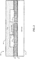
- FIG. 2 shows the cross-section of the multi-axis integrated inertial sensor device.
- device 200 includes a semiconductor substrate 210, which can have a central region and a border region around the central region.
- a three-axis accelerometer 230 can be formed within the central region of the semiconductor substrate 210 and a three-axis gyroscope 220 can be formed within the central region of the semiconductor substrate.
- layers 211 and 212 can include passivation or dielectric layers.
- An optional design involves using a Z travel stop structure in a cap wafer to adjust damping performance in the central area of the chip, where the accelerometer device is disposed.
- the "Z Travel Stop” structure is shown by the lower ceiling of the cap wafer overlying the accel portion compared to the higher ceiling overlying the gyro portion.
- This configuration can be used to mitigate a phenomenon called “accelerometer ringing", which can be undesirable for various applications.
- Certain closed-loop feedback systems might be needed to control sensor ringing.
- the present design can alleviate "Accel ringing" during operation and allow a low damping gyroscope and a high damping accelerometer to coexist within a single package.
- Embodiments of the disclosure relate to a multi-axis integrated MEMS inertial sensor device.
- the device includes an integrated 3-axis gyroscope and 3-axis accelerometer on a single chip, creating a 6-axis inertial sensor device.
- the structure may provide spatially efficient use of the design area of the chip by adding the accelerometer device to the center of the gyroscope device.
- the design architecture can be a rectangular or square shape in geometry, which makes use of the whole chip area and maximizes the sensor size in a defined area.
- the MEMS is centered in the package, which may be beneficial to the sensor's temperature performance.
- the electrical bonding pads of the integrated multi-axis inertial sensor device can be configured in the four corners of the rectangular chip layout. This configuration may assist design symmetry and efficient use of the chip area.
Landscapes
- Physics & Mathematics (AREA)
- General Physics & Mathematics (AREA)
- Engineering & Computer Science (AREA)
- Radar, Positioning & Navigation (AREA)
- Remote Sensing (AREA)
- Microelectronics & Electronic Packaging (AREA)
- Computer Hardware Design (AREA)
- Gyroscopes (AREA)
- Pressure Sensors (AREA)
- Micromachines (AREA)
Claims (9)
- Mehrachsige integrierte MEMS-Trägheitsmessvorrichtung, wobei die Vorrichtung Folgendes umfasst:ein Substratelement mit einem Oberflächenbereich, wobei der Oberflächenbereich einen inneren Abschnitt und einen äußeren Abschnitt aufweist, wobei der äußere Abschnitt den inneren Abschnitt umgibt und der äußere Abschnitt mindestens vier Ecken aufweist;einen ersten MEMS-Trägheitssensor, der über dem inneren Abschnitt des Oberflächenbereichs liegt, wobei der erste MEMS-Trägheitssensor einen dreiachsigen Beschleunigungsmesser umfasst; undeinen zweiten MEMS-Trägheitssensor, der über dem äußeren Abschnitt des Oberflächenbereichs liegt, wobei der zweite MEMS-Trägheitssensor ein dreiachsiges Gyroskop umfasst;dadurch gekennzeichnet dass: die genannte Vorrichtung ferner mindestens ein Bindungsstück umfasst, das über jeder Ecke des äußeren Abschnitts des Oberflächenbereichs angeordnet ist; und
das genannte dreiachsige Gyroskop drei Paare von einachsigen Gyroskopsensoren aufweist, wobei die zwei einachsigen Gyroskopsensoren jedes Paares so konfiguriert sind, dass sie entlang einer gemeinsamen Richtung im Raum abtasten und symmetrisch an gegenüberliegenden Seiten des dreiachsigen Beschleunigungsmessers in einer symmetrischen rechteckigen oder quadratischen Geometrie angeordnet sind, wobei zwei der Paare von einachsigen Gyroskopsensoren entlang einer ersten Achse des Substratelements angeordnet sind und eines der Paare von einachsigen Gyroskopsensoren entlang einer zweiten Achse des Substratelements orthogonal zur ersten Achse des Substratelements angeordnet ist. - Vorrichtung nach Anspruch 1, wobei jeder einachsige Gyroskopsensor Folgendes umfasst: eine jeweilige Prüfmasse (120), die an dem Substratelement innerhalb des äußeren Abschnitts verankert ist, einen jeweiligen Verschiebungssensor (122) und einen jeweiligen Verschiebungstreiber (123), der dafür konfiguriert ist, die Prüfmasse (120) zu verschieben, und wobei jeder jeweilige Verschiebungssensor Verschiebungsdaten als Reaktion auf eine Verschiebung der jeweiligen Prüfmasse durch den jeweiligen Verschiebungstreiber bereitstellt.
- Vorrichtung nach Anspruch 1, wobei der dreiachsige Gyroskop eine Einzelmaskenschichtvorrichtung ist.
- Vorrichtung nach Anspruch 3, wobei der dreiachsige Gyroskop sechs oder mehr Prüfmassen aufweist, die innerhalb des äußeren Abschnitts an dem Substratelement verankert sind.
- Vorrichtung nach Anspruch 1, wobei der innere Abschnitt durch eine geometrische Form gekennzeichnet ist, die aus einer Gruppe ausgewählt wird, die aus Folgendem besteht: etwa rechteckig, etwa quadratisch, etwa vierseitig, und etwa polygonal.
- Vorrichtung nach Anspruch 5, wobei der dreiachsige Beschleunigungsmesser eine Prüfmasse umfasst, die auf dem Halbleitersubstrat innerhalb des inneren Abschnitts verankert ist.
- Vorrichtung nach einem der vorhergehenden Ansprüche, die ferner einen Kappenwafer mit einer Z-Weg-Stoppstruktur umfasst, die räumlich so konfiguriert ist, dass sie mindestens über dem inneren Abschnitt und dem äußeren Abschnitt liegt.
- Vorrichtung nach Anspruch 7, wobei die Z-Weg-Stoppstruktur räumlich über dem inneren Abschnitt angeordnet ist und das dreiachsige Gyroskop eine Prüfmasse umfasst, die an dem Halbleitersubstrat innerhalb des äußeren Abschnitts, der in der Nähe des inneren Abschnitts liegt, verankert ist.
- Vorrichtung nach Anspruch 1, wobei das dreiachsige Gyroskop ein Paar einachsiger Gyroskopsensoren für jede x-, y- und z-Achse umfasst, wobei die zwei einachsigen Gyroskopsensoren jedes Paares symmetrisch an gegenüberliegenden Seiten des dreiachsigen Beschleunigungsmessers angeordnet sind, wobei das x-Achsenpaar einachsiger Gyroskopsensoren entlang einer Achse des Substrats angeordnet ist und das y-Achsenpaar von einachsigen Gyroskopsensoren und das Z-Achsenpaar von einachsigen Gyroskopsensoren entlang einer orthogonalen Achse des Substrats angeordnet sind, wobei jeder einachsige y-Achsen-Gyroskopsensor zwischen dem dreiachsigen Beschleunigungsmesser und einem jeweiligen der einachsigen Z-Achsen-Gyroskopsensoren angeordnet ist.
Applications Claiming Priority (3)
| Application Number | Priority Date | Filing Date | Title |
|---|---|---|---|
| US201361757085P | 2013-01-25 | 2013-01-25 | |
| US201361757088P | 2013-01-25 | 2013-01-25 | |
| US14/162,718 US10132630B2 (en) | 2013-01-25 | 2014-01-23 | Multi-axis integrated MEMS inertial sensing device on single packaged chip |
Publications (3)
| Publication Number | Publication Date |
|---|---|
| EP2759802A2 EP2759802A2 (de) | 2014-07-30 |
| EP2759802A3 EP2759802A3 (de) | 2014-10-01 |
| EP2759802B1 true EP2759802B1 (de) | 2019-01-02 |
Family
ID=50033336
Family Applications (1)
| Application Number | Title | Priority Date | Filing Date |
|---|---|---|---|
| EP14152747.3A Active EP2759802B1 (de) | 2013-01-25 | 2014-01-27 | Mehrachsige integrierte MEMS-Trägheitsmessungsvorrichtung auf Chip mit Einzelgehäuse |
Country Status (3)
| Country | Link |
|---|---|
| US (1) | US10132630B2 (de) |
| EP (1) | EP2759802B1 (de) |
| TW (1) | TWI518302B (de) |
Families Citing this family (25)
| Publication number | Priority date | Publication date | Assignee | Title |
|---|---|---|---|---|
| US10036635B2 (en) | 2013-01-25 | 2018-07-31 | MCube Inc. | Multi-axis MEMS rate sensor device |
| US10046964B2 (en) | 2013-03-07 | 2018-08-14 | MCube Inc. | MEMS structure with improved shielding and method |
| US10273147B2 (en) | 2013-07-08 | 2019-04-30 | Motion Engine Inc. | MEMS components and method of wafer-level manufacturing thereof |
| JP6339669B2 (ja) | 2013-07-08 | 2018-06-06 | モーション・エンジン・インコーポレーテッド | Memsデバイスおよび製造する方法 |
| WO2015013827A1 (en) | 2013-08-02 | 2015-02-05 | Motion Engine Inc. | Mems motion sensor for sub-resonance angular rate sensing |
| WO2015103688A1 (en) | 2014-01-09 | 2015-07-16 | Motion Engine Inc. | Integrated mems system |
| US20170030788A1 (en) | 2014-04-10 | 2017-02-02 | Motion Engine Inc. | Mems pressure sensor |
| US11674803B2 (en) | 2014-06-02 | 2023-06-13 | Motion Engine, Inc. | Multi-mass MEMS motion sensor |
| US11287486B2 (en) | 2014-12-09 | 2022-03-29 | Motion Engine, Inc. | 3D MEMS magnetometer and associated methods |
| US10407299B2 (en) | 2015-01-15 | 2019-09-10 | Motion Engine Inc. | 3D MEMS device with hermetic cavity |
| TWI556169B (zh) | 2015-03-24 | 2016-11-01 | 溫瓌岸 | 泛用型多功能感測器服務平台 |
| CN104807454B (zh) * | 2015-04-29 | 2017-07-18 | 东南大学 | 一种单片集成六自由度微惯性测量单元及其加工方法 |
| DE102016122042B4 (de) | 2015-11-20 | 2022-02-17 | Jena Optronik Gmbh | Sensorbaugruppe zur Lageermittlung eines Objekts |
| US10209157B2 (en) | 2015-12-10 | 2019-02-19 | Invensense, Inc. | Dual-sealed MEMS package with cavity pressure monitoring |
| US10041854B2 (en) * | 2015-12-10 | 2018-08-07 | Panasonic Corporation | Identification of a seal failure in MEMS devices |
| DE102016214962A1 (de) * | 2016-08-11 | 2018-02-15 | Robert Bosch Gmbh | Mikromechanischer Sensorkern für Inertialsensor |
| EP3315975B1 (de) * | 2016-10-26 | 2019-04-24 | NXP USA, Inc. | Haftreibungserkennung und wiederherstellung in einer mikro-elektromechanischen systemvorrichtung |
| US10239746B2 (en) * | 2016-11-11 | 2019-03-26 | Analog Devices, Inc. | Vertical stopper for capping MEMS devices |
| CN107063223B (zh) * | 2017-04-17 | 2019-04-30 | 东南大学 | 单片式谐振加速度计陀螺仪结构 |
| DE102017208357B4 (de) * | 2017-05-18 | 2025-01-02 | Robert Bosch Gmbh | Mikroelektromechanisches Bauelement mit vertikalem Anschlag |
| US11005167B2 (en) * | 2017-11-03 | 2021-05-11 | Antenum Llc | Low profile antenna-conformal one dimensional |
| US11733263B2 (en) | 2018-09-21 | 2023-08-22 | Analog Devices, Inc. | 3-axis accelerometer |
| US11891297B2 (en) * | 2019-07-05 | 2024-02-06 | Aac Acoustic Technologies (Shenzhen) Co., Ltd. | Motion control structure and actuator |
| CN113654552B (zh) * | 2021-06-30 | 2024-12-10 | 贵州航天控制技术有限公司 | 一种能抗大过载的mems惯性测量装置 |
| CN115727827B (zh) * | 2021-09-01 | 2025-12-23 | 美新半导体(天津)有限公司 | 单芯片上的多轴mems传感融合装置 |
Family Cites Families (41)
| Publication number | Priority date | Publication date | Assignee | Title |
|---|---|---|---|---|
| JP4075022B2 (ja) * | 1998-06-24 | 2008-04-16 | アイシン精機株式会社 | 角速度センサ |
| KR100436367B1 (ko) * | 2001-12-14 | 2004-06-19 | 삼성전자주식회사 | 수직 진동 질량체를 갖는 멤스 자이로스코프 |
| US6859751B2 (en) * | 2001-12-17 | 2005-02-22 | Milli Sensor Systems & Actuators, Inc. | Planar inertial measurement units based on gyros and accelerometers with a common structure |
| US6725719B2 (en) | 2002-04-17 | 2004-04-27 | Milli Sensor Systems And Actuators, Inc. | MEMS-integrated inertial measurement units on a common substrate |
| US7122395B2 (en) | 2002-12-23 | 2006-10-17 | Motorola, Inc. | Method of forming semiconductor devices through epitaxy |
| WO2004077073A1 (en) * | 2003-02-24 | 2004-09-10 | University Of Florida | Integrated monolithic tri-axial micromachined accelerometer |
| US7368312B1 (en) * | 2004-10-15 | 2008-05-06 | Morgan Research Corporation | MEMS sensor suite on a chip |
| US7562573B2 (en) * | 2005-07-21 | 2009-07-21 | Evigia Systems, Inc. | Integrated sensor and circuitry and process therefor |
| US7621183B2 (en) * | 2005-11-18 | 2009-11-24 | Invensense Inc. | X-Y axis dual-mass tuning fork gyroscope with vertically integrated electronics and wafer-scale hermetic packaging |
| US20070164378A1 (en) * | 2006-01-13 | 2007-07-19 | Honeywell International Inc. | Integrated mems package |
| US7578189B1 (en) * | 2006-05-10 | 2009-08-25 | Qualtre, Inc. | Three-axis accelerometers |
| US7900512B2 (en) | 2006-07-25 | 2011-03-08 | Denso Corporation | Angular rate sensor |
| US8047075B2 (en) * | 2007-06-21 | 2011-11-01 | Invensense, Inc. | Vertically integrated 3-axis MEMS accelerometer with electronics |
| US20100071467A1 (en) | 2008-09-24 | 2010-03-25 | Invensense | Integrated multiaxis motion sensor |
| US7923790B1 (en) | 2007-03-09 | 2011-04-12 | Silicon Laboratories Inc. | Planar microshells for vacuum encapsulated devices and damascene method of manufacture |
| US8061201B2 (en) | 2007-07-13 | 2011-11-22 | Georgia Tech Research Corporation | Readout method and electronic bandwidth control for a silicon in-plane tuning fork gyroscope |
| US7677099B2 (en) * | 2007-11-05 | 2010-03-16 | Invensense Inc. | Integrated microelectromechanical systems (MEMS) vibrating mass Z-axis rate sensor |
| JP4508230B2 (ja) * | 2007-11-21 | 2010-07-21 | ソニー株式会社 | 慣性センサ及びその検出装置 |
| US8156806B1 (en) * | 2007-12-10 | 2012-04-17 | Milli Sensor Systems & Actuators | Inertial measurement unit for spin-stabilized aerial vehicles, and method of providing guidance information using same |
| US7800190B2 (en) | 2008-06-16 | 2010-09-21 | Honeywell International Inc. | Getter on die in an upper sense plate designed system |
| US8939029B2 (en) | 2008-09-05 | 2015-01-27 | Analog Devices, Inc. | MEMS sensor with movable Z-axis sensing element |
| US7966880B2 (en) * | 2008-10-13 | 2011-06-28 | Hewlett-Packard Development Company, L.P. | Adjusting the damping level of an encapsulated device |
| US8205498B2 (en) | 2008-11-18 | 2012-06-26 | Industrial Technology Research Institute | Multi-axis capacitive accelerometer |
| TW201020548A (en) | 2008-11-18 | 2010-06-01 | Ind Tech Res Inst | Multi-axis capacitive accelerometer |
| GB2467776A (en) | 2009-02-13 | 2010-08-18 | Wolfson Microelectronics Plc | Integrated MEMS transducer and circuitry |
| WO2010107016A1 (ja) | 2009-03-16 | 2010-09-23 | パナソニック電工株式会社 | Memsデバイス |
| IT1394007B1 (it) * | 2009-05-11 | 2012-05-17 | St Microelectronics Rousset | Struttura microelettromeccanica con reiezione migliorata di disturbi di accelerazione |
| US8164171B2 (en) | 2009-05-14 | 2012-04-24 | Megica Corporation | System-in packages |
| FR2945621B1 (fr) * | 2009-05-15 | 2011-08-26 | Commissariat Energie Atomique | Structure de couplage pour gyrometre resonnant |
| US8823007B2 (en) | 2009-10-28 | 2014-09-02 | MCube Inc. | Integrated system on chip using multiple MEMS and CMOS devices |
| US8739626B2 (en) | 2009-08-04 | 2014-06-03 | Fairchild Semiconductor Corporation | Micromachined inertial sensor devices |
| ITTO20091042A1 (it) | 2009-12-24 | 2011-06-25 | St Microelectronics Srl | Giroscopio integrato microelettromeccanico con migliorata struttura di azionamento |
| US8584522B2 (en) * | 2010-04-30 | 2013-11-19 | Qualcomm Mems Technologies, Inc. | Micromachined piezoelectric x-axis gyroscope |
| US8487398B2 (en) | 2010-07-14 | 2013-07-16 | Freescale Semiconductor, Inc. | Capacitor device using an isolated well and method therefor |
| US9455354B2 (en) | 2010-09-18 | 2016-09-27 | Fairchild Semiconductor Corporation | Micromachined 3-axis accelerometer with a single proof-mass |
| CN103492885A (zh) | 2010-12-08 | 2014-01-01 | 晶致材料科技私人有限公司 | 高性能弯曲加速度计 |
| US8878312B2 (en) | 2011-03-01 | 2014-11-04 | Taiwan Semiconductor Manufacturing Company, Ltd. | Electrical bypass structure for MEMS device |
| US9540230B2 (en) | 2011-06-27 | 2017-01-10 | Invensense, Inc. | Methods for CMOS-MEMS integrated devices with multiple sealed cavities maintained at various pressures |
| US20130042686A1 (en) | 2011-08-17 | 2013-02-21 | Sitronix Technology Corp. | Inertia sensing apparatus |
| US9249012B2 (en) | 2013-01-25 | 2016-02-02 | Mcube, Inc. | Method and device of MEMS process control monitoring and packaged MEMS with different cavity pressures |
| US10036635B2 (en) | 2013-01-25 | 2018-07-31 | MCube Inc. | Multi-axis MEMS rate sensor device |
-
2014
- 2014-01-23 US US14/162,718 patent/US10132630B2/en active Active
- 2014-01-27 EP EP14152747.3A patent/EP2759802B1/de active Active
- 2014-01-27 TW TW103103000A patent/TWI518302B/zh active
Non-Patent Citations (1)
| Title |
|---|
| None * |
Also Published As
| Publication number | Publication date |
|---|---|
| TWI518302B (zh) | 2016-01-21 |
| EP2759802A2 (de) | 2014-07-30 |
| US20140311242A1 (en) | 2014-10-23 |
| US10132630B2 (en) | 2018-11-20 |
| EP2759802A3 (de) | 2014-10-01 |
| TW201435306A (zh) | 2014-09-16 |
Similar Documents
| Publication | Publication Date | Title |
|---|---|---|
| EP2759802B1 (de) | Mehrachsige integrierte MEMS-Trägheitsmessungsvorrichtung auf Chip mit Einzelgehäuse | |
| US10036635B2 (en) | Multi-axis MEMS rate sensor device | |
| US8794065B1 (en) | Integrated inertial sensing apparatus using MEMS and quartz configured on crystallographic planes | |
| CN103221778B (zh) | 具有单驱动的微机械单片式三轴陀螺仪 | |
| US9650237B2 (en) | Electromechanical device including a suspended structure and method of fabricating the same | |
| US9075079B2 (en) | Method and structure of an integrated MEMS inertial sensor device using electrostatic quadrature-cancellation | |
| US9095072B2 (en) | Multi-die MEMS package | |
| US10732196B2 (en) | Asymmetric out-of-plane accelerometer | |
| CN103303859B (zh) | 用于集成mems‑cmos装置的方法和结构 | |
| US20140227816A1 (en) | Method to package multiple mems sensors and actuators at different gases and cavity pressures | |
| US20130104651A1 (en) | Inertial sensor with off-axis spring system | |
| US9476711B2 (en) | Angular rate sensor with quadrature error compensation | |
| CN103542844A (zh) | 带有正交误差补偿的角速率传感器 | |
| CN209485368U (zh) | 微机械陀螺仪 | |
| JP2016149539A (ja) | パターン化されたインターポーザを備えるパッケージ化マイクロチップ | |
| Acar | High-performance 6-Axis MEMS inertial sensor based on Through-Silicon Via technology | |
| JP2022052997A (ja) | 物理量センサー及び慣性計測装置 | |
| US11761977B1 (en) | MEMS design with shear force rejection for reduced offset | |
| US8584521B1 (en) | Accurate gyroscope device using MEMS and quartz | |
| US9321629B2 (en) | Method and structure for adding mass with stress isolation to MEMS structures | |
| US20250164520A1 (en) | Anchoring Structure for MEMS Accelerometers with Bend Offset Shift Rejection | |
| WO2025111288A1 (en) | Anchoring structure for mems accelerometers with bend offset shift rejection | |
| US8564075B1 (en) | Package tolerate design and method | |
| JP2008128879A (ja) | 角速度センサ | |
| KR20180016219A (ko) | 충격 특성이 개선된 mems 장치, 이를 포함하는 mems 패키지, 컴퓨팅 시스템, 및 그 제조 방법 |
Legal Events
| Date | Code | Title | Description |
|---|---|---|---|
| PUAI | Public reference made under article 153(3) epc to a published international application that has entered the european phase |
Free format text: ORIGINAL CODE: 0009012 |
|
| 17P | Request for examination filed |
Effective date: 20140127 |
|
| AK | Designated contracting states |
Kind code of ref document: A2 Designated state(s): AL AT BE BG CH CY CZ DE DK EE ES FI FR GB GR HR HU IE IS IT LI LT LU LV MC MK MT NL NO PL PT RO RS SE SI SK SM TR |
|
| AX | Request for extension of the european patent |
Extension state: BA ME |
|
| PUAL | Search report despatched |
Free format text: ORIGINAL CODE: 0009013 |
|
| AK | Designated contracting states |
Kind code of ref document: A3 Designated state(s): AL AT BE BG CH CY CZ DE DK EE ES FI FR GB GR HR HU IE IS IT LI LT LU LV MC MK MT NL NO PL PT RO RS SE SI SK SM TR |
|
| AX | Request for extension of the european patent |
Extension state: BA ME |
|
| RIC1 | Information provided on ipc code assigned before grant |
Ipc: G01C 19/5783 20120101AFI20140828BHEP Ipc: G01P 1/02 20060101ALI20140828BHEP |
|
| R17P | Request for examination filed (corrected) |
Effective date: 20150331 |
|
| RBV | Designated contracting states (corrected) |
Designated state(s): AL AT BE BG CH CY CZ DE DK EE ES FI FR GB GR HR HU IE IS IT LI LT LU LV MC MK MT NL NO PL PT RO RS SE SI SK SM TR |
|
| 17Q | First examination report despatched |
Effective date: 20160304 |
|
| STAA | Information on the status of an ep patent application or granted ep patent |
Free format text: STATUS: EXAMINATION IS IN PROGRESS |
|
| GRAP | Despatch of communication of intention to grant a patent |
Free format text: ORIGINAL CODE: EPIDOSNIGR1 |
|
| STAA | Information on the status of an ep patent application or granted ep patent |
Free format text: STATUS: GRANT OF PATENT IS INTENDED |
|
| INTG | Intention to grant announced |
Effective date: 20180724 |
|
| GRAS | Grant fee paid |
Free format text: ORIGINAL CODE: EPIDOSNIGR3 |
|
| GRAA | (expected) grant |
Free format text: ORIGINAL CODE: 0009210 |
|
| STAA | Information on the status of an ep patent application or granted ep patent |
Free format text: STATUS: THE PATENT HAS BEEN GRANTED |
|
| AK | Designated contracting states |
Kind code of ref document: B1 Designated state(s): AL AT BE BG CH CY CZ DE DK EE ES FI FR GB GR HR HU IE IS IT LI LT LU LV MC MK MT NL NO PL PT RO RS SE SI SK SM TR |
|
| REG | Reference to a national code |
Ref country code: GB Ref legal event code: FG4D |
|
| REG | Reference to a national code |
Ref country code: CH Ref legal event code: EP Ref country code: AT Ref legal event code: REF Ref document number: 1084947 Country of ref document: AT Kind code of ref document: T Effective date: 20190115 |
|
| REG | Reference to a national code |
Ref country code: IE Ref legal event code: FG4D |
|
| REG | Reference to a national code |
Ref country code: DE Ref legal event code: R096 Ref document number: 602014038945 Country of ref document: DE |
|
| REG | Reference to a national code |
Ref country code: NL Ref legal event code: MP Effective date: 20190102 |
|
| REG | Reference to a national code |
Ref country code: LT Ref legal event code: MG4D |
|
| REG | Reference to a national code |
Ref country code: AT Ref legal event code: MK05 Ref document number: 1084947 Country of ref document: AT Kind code of ref document: T Effective date: 20190102 |
|
| PG25 | Lapsed in a contracting state [announced via postgrant information from national office to epo] |
Ref country code: NL Free format text: LAPSE BECAUSE OF FAILURE TO SUBMIT A TRANSLATION OF THE DESCRIPTION OR TO PAY THE FEE WITHIN THE PRESCRIBED TIME-LIMIT Effective date: 20190102 |
|
| PG25 | Lapsed in a contracting state [announced via postgrant information from national office to epo] |
Ref country code: FI Free format text: LAPSE BECAUSE OF FAILURE TO SUBMIT A TRANSLATION OF THE DESCRIPTION OR TO PAY THE FEE WITHIN THE PRESCRIBED TIME-LIMIT Effective date: 20190102 Ref country code: LT Free format text: LAPSE BECAUSE OF FAILURE TO SUBMIT A TRANSLATION OF THE DESCRIPTION OR TO PAY THE FEE WITHIN THE PRESCRIBED TIME-LIMIT Effective date: 20190102 Ref country code: ES Free format text: LAPSE BECAUSE OF FAILURE TO SUBMIT A TRANSLATION OF THE DESCRIPTION OR TO PAY THE FEE WITHIN THE PRESCRIBED TIME-LIMIT Effective date: 20190102 Ref country code: PL Free format text: LAPSE BECAUSE OF FAILURE TO SUBMIT A TRANSLATION OF THE DESCRIPTION OR TO PAY THE FEE WITHIN THE PRESCRIBED TIME-LIMIT Effective date: 20190102 Ref country code: NO Free format text: LAPSE BECAUSE OF FAILURE TO SUBMIT A TRANSLATION OF THE DESCRIPTION OR TO PAY THE FEE WITHIN THE PRESCRIBED TIME-LIMIT Effective date: 20190402 Ref country code: SE Free format text: LAPSE BECAUSE OF FAILURE TO SUBMIT A TRANSLATION OF THE DESCRIPTION OR TO PAY THE FEE WITHIN THE PRESCRIBED TIME-LIMIT Effective date: 20190102 Ref country code: PT Free format text: LAPSE BECAUSE OF FAILURE TO SUBMIT A TRANSLATION OF THE DESCRIPTION OR TO PAY THE FEE WITHIN THE PRESCRIBED TIME-LIMIT Effective date: 20190502 |
|
| REG | Reference to a national code |
Ref country code: DE Ref legal event code: R119 Ref document number: 602014038945 Country of ref document: DE |
|
| PG25 | Lapsed in a contracting state [announced via postgrant information from national office to epo] |
Ref country code: LV Free format text: LAPSE BECAUSE OF FAILURE TO SUBMIT A TRANSLATION OF THE DESCRIPTION OR TO PAY THE FEE WITHIN THE PRESCRIBED TIME-LIMIT Effective date: 20190102 Ref country code: RS Free format text: LAPSE BECAUSE OF FAILURE TO SUBMIT A TRANSLATION OF THE DESCRIPTION OR TO PAY THE FEE WITHIN THE PRESCRIBED TIME-LIMIT Effective date: 20190102 Ref country code: HR Free format text: LAPSE BECAUSE OF FAILURE TO SUBMIT A TRANSLATION OF THE DESCRIPTION OR TO PAY THE FEE WITHIN THE PRESCRIBED TIME-LIMIT Effective date: 20190102 Ref country code: IS Free format text: LAPSE BECAUSE OF FAILURE TO SUBMIT A TRANSLATION OF THE DESCRIPTION OR TO PAY THE FEE WITHIN THE PRESCRIBED TIME-LIMIT Effective date: 20190502 Ref country code: BG Free format text: LAPSE BECAUSE OF FAILURE TO SUBMIT A TRANSLATION OF THE DESCRIPTION OR TO PAY THE FEE WITHIN THE PRESCRIBED TIME-LIMIT Effective date: 20190402 Ref country code: GR Free format text: LAPSE BECAUSE OF FAILURE TO SUBMIT A TRANSLATION OF THE DESCRIPTION OR TO PAY THE FEE WITHIN THE PRESCRIBED TIME-LIMIT Effective date: 20190403 |
|
| REG | Reference to a national code |
Ref country code: CH Ref legal event code: PL |
|
| PG25 | Lapsed in a contracting state [announced via postgrant information from national office to epo] |
Ref country code: LU Free format text: LAPSE BECAUSE OF NON-PAYMENT OF DUE FEES Effective date: 20190127 |
|
| REG | Reference to a national code |
Ref country code: BE Ref legal event code: MM Effective date: 20190131 |
|
| REG | Reference to a national code |
Ref country code: IE Ref legal event code: MM4A |
|
| PG25 | Lapsed in a contracting state [announced via postgrant information from national office to epo] |
Ref country code: DK Free format text: LAPSE BECAUSE OF FAILURE TO SUBMIT A TRANSLATION OF THE DESCRIPTION OR TO PAY THE FEE WITHIN THE PRESCRIBED TIME-LIMIT Effective date: 20190102 Ref country code: AT Free format text: LAPSE BECAUSE OF FAILURE TO SUBMIT A TRANSLATION OF THE DESCRIPTION OR TO PAY THE FEE WITHIN THE PRESCRIBED TIME-LIMIT Effective date: 20190102 Ref country code: MC Free format text: LAPSE BECAUSE OF FAILURE TO SUBMIT A TRANSLATION OF THE DESCRIPTION OR TO PAY THE FEE WITHIN THE PRESCRIBED TIME-LIMIT Effective date: 20190102 Ref country code: CZ Free format text: LAPSE BECAUSE OF FAILURE TO SUBMIT A TRANSLATION OF THE DESCRIPTION OR TO PAY THE FEE WITHIN THE PRESCRIBED TIME-LIMIT Effective date: 20190102 Ref country code: SK Free format text: LAPSE BECAUSE OF FAILURE TO SUBMIT A TRANSLATION OF THE DESCRIPTION OR TO PAY THE FEE WITHIN THE PRESCRIBED TIME-LIMIT Effective date: 20190102 Ref country code: RO Free format text: LAPSE BECAUSE OF FAILURE TO SUBMIT A TRANSLATION OF THE DESCRIPTION OR TO PAY THE FEE WITHIN THE PRESCRIBED TIME-LIMIT Effective date: 20190102 Ref country code: AL Free format text: LAPSE BECAUSE OF FAILURE TO SUBMIT A TRANSLATION OF THE DESCRIPTION OR TO PAY THE FEE WITHIN THE PRESCRIBED TIME-LIMIT Effective date: 20190102 Ref country code: DE Free format text: LAPSE BECAUSE OF NON-PAYMENT OF DUE FEES Effective date: 20190801 Ref country code: EE Free format text: LAPSE BECAUSE OF FAILURE TO SUBMIT A TRANSLATION OF THE DESCRIPTION OR TO PAY THE FEE WITHIN THE PRESCRIBED TIME-LIMIT Effective date: 20190102 |
|
| PLBE | No opposition filed within time limit |
Free format text: ORIGINAL CODE: 0009261 |
|
| STAA | Information on the status of an ep patent application or granted ep patent |
Free format text: STATUS: NO OPPOSITION FILED WITHIN TIME LIMIT |
|
| PG25 | Lapsed in a contracting state [announced via postgrant information from national office to epo] |
Ref country code: SM Free format text: LAPSE BECAUSE OF FAILURE TO SUBMIT A TRANSLATION OF THE DESCRIPTION OR TO PAY THE FEE WITHIN THE PRESCRIBED TIME-LIMIT Effective date: 20190102 Ref country code: BE Free format text: LAPSE BECAUSE OF NON-PAYMENT OF DUE FEES Effective date: 20190131 |
|
| 26N | No opposition filed |
Effective date: 20191003 |
|
| GBPC | Gb: european patent ceased through non-payment of renewal fee |
Effective date: 20190402 |
|
| PG25 | Lapsed in a contracting state [announced via postgrant information from national office to epo] |
Ref country code: LI Free format text: LAPSE BECAUSE OF NON-PAYMENT OF DUE FEES Effective date: 20190131 Ref country code: CH Free format text: LAPSE BECAUSE OF NON-PAYMENT OF DUE FEES Effective date: 20190131 |
|
| PG25 | Lapsed in a contracting state [announced via postgrant information from national office to epo] |
Ref country code: GB Free format text: LAPSE BECAUSE OF NON-PAYMENT OF DUE FEES Effective date: 20190402 Ref country code: IE Free format text: LAPSE BECAUSE OF NON-PAYMENT OF DUE FEES Effective date: 20190127 |
|
| PG25 | Lapsed in a contracting state [announced via postgrant information from national office to epo] |
Ref country code: SI Free format text: LAPSE BECAUSE OF FAILURE TO SUBMIT A TRANSLATION OF THE DESCRIPTION OR TO PAY THE FEE WITHIN THE PRESCRIBED TIME-LIMIT Effective date: 20190102 |
|
| PG25 | Lapsed in a contracting state [announced via postgrant information from national office to epo] |
Ref country code: TR Free format text: LAPSE BECAUSE OF FAILURE TO SUBMIT A TRANSLATION OF THE DESCRIPTION OR TO PAY THE FEE WITHIN THE PRESCRIBED TIME-LIMIT Effective date: 20190102 |
|
| PG25 | Lapsed in a contracting state [announced via postgrant information from national office to epo] |
Ref country code: MT Free format text: LAPSE BECAUSE OF NON-PAYMENT OF DUE FEES Effective date: 20190127 |
|
| PG25 | Lapsed in a contracting state [announced via postgrant information from national office to epo] |
Ref country code: CY Free format text: LAPSE BECAUSE OF FAILURE TO SUBMIT A TRANSLATION OF THE DESCRIPTION OR TO PAY THE FEE WITHIN THE PRESCRIBED TIME-LIMIT Effective date: 20190102 |
|
| PG25 | Lapsed in a contracting state [announced via postgrant information from national office to epo] |
Ref country code: HU Free format text: LAPSE BECAUSE OF FAILURE TO SUBMIT A TRANSLATION OF THE DESCRIPTION OR TO PAY THE FEE WITHIN THE PRESCRIBED TIME-LIMIT; INVALID AB INITIO Effective date: 20140127 |
|
| PG25 | Lapsed in a contracting state [announced via postgrant information from national office to epo] |
Ref country code: MK Free format text: LAPSE BECAUSE OF FAILURE TO SUBMIT A TRANSLATION OF THE DESCRIPTION OR TO PAY THE FEE WITHIN THE PRESCRIBED TIME-LIMIT Effective date: 20190102 |
|
| PGFP | Annual fee paid to national office [announced via postgrant information from national office to epo] |
Ref country code: FR Payment date: 20251219 Year of fee payment: 13 |
|
| PGFP | Annual fee paid to national office [announced via postgrant information from national office to epo] |
Ref country code: IT Payment date: 20260126 Year of fee payment: 13 |