EP2759781B1 - Floor-standing indoor unit of air-conditioning apparatus - Google Patents
Floor-standing indoor unit of air-conditioning apparatus Download PDFInfo
- Publication number
- EP2759781B1 EP2759781B1 EP13190967.3A EP13190967A EP2759781B1 EP 2759781 B1 EP2759781 B1 EP 2759781B1 EP 13190967 A EP13190967 A EP 13190967A EP 2759781 B1 EP2759781 B1 EP 2759781B1
- Authority
- EP
- European Patent Office
- Prior art keywords
- panel
- design panel
- casing
- floor
- indoor unit
- Prior art date
- Legal status (The legal status is an assumption and is not a legal conclusion. Google has not performed a legal analysis and makes no representation as to the accuracy of the status listed.)
- Not-in-force
Links
Images
Classifications
-
- F—MECHANICAL ENGINEERING; LIGHTING; HEATING; WEAPONS; BLASTING
- F24—HEATING; RANGES; VENTILATING
- F24F—AIR-CONDITIONING; AIR-HUMIDIFICATION; VENTILATION; USE OF AIR CURRENTS FOR SCREENING
- F24F13/00—Details common to, or for air-conditioning, air-humidification, ventilation or use of air currents for screening
- F24F13/20—Casings or covers
-
- F—MECHANICAL ENGINEERING; LIGHTING; HEATING; WEAPONS; BLASTING
- F24—HEATING; RANGES; VENTILATING
- F24F—AIR-CONDITIONING; AIR-HUMIDIFICATION; VENTILATION; USE OF AIR CURRENTS FOR SCREENING
- F24F1/00—Room units for air-conditioning, e.g. separate or self-contained units or units receiving primary air from a central station
- F24F1/0007—Indoor units, e.g. fan coil units
- F24F1/0043—Indoor units, e.g. fan coil units characterised by mounting arrangements
- F24F1/005—Indoor units, e.g. fan coil units characterised by mounting arrangements mounted on the floor; standing on the floor
-
- F—MECHANICAL ENGINEERING; LIGHTING; HEATING; WEAPONS; BLASTING
- F24—HEATING; RANGES; VENTILATING
- F24F—AIR-CONDITIONING; AIR-HUMIDIFICATION; VENTILATION; USE OF AIR CURRENTS FOR SCREENING
- F24F13/00—Details common to, or for air-conditioning, air-humidification, ventilation or use of air currents for screening
- F24F13/08—Air-flow control members, e.g. louvres, grilles, flaps or guide plates
- F24F13/082—Grilles, registers or guards
- F24F13/084—Grilles, registers or guards with mounting arrangements, e.g. snap fasteners for mounting to the wall or duct
-
- F—MECHANICAL ENGINEERING; LIGHTING; HEATING; WEAPONS; BLASTING
- F24—HEATING; RANGES; VENTILATING
- F24F—AIR-CONDITIONING; AIR-HUMIDIFICATION; VENTILATION; USE OF AIR CURRENTS FOR SCREENING
- F24F2221/00—Details or features not otherwise provided for
- F24F2221/26—Details or features not otherwise provided for improving the aesthetic appearance
Definitions
- the present invention relates to a floor-standing indoor unit of an air-conditioning apparatus, and more specifically, it relates to a casing of the floor-standing indoor unit and to a mechanism in which a design panel is attached to the casing.
- a shaft that holds a design panel coincides with the center of rotation of the design panel that is opened or closed. In opening the design panel, the design panel is moved upward. Meanwhile, a securing portion has a shape that allows the design panel s to rotate (see Patent Literature 1, for example).
- Patent Literature 1 Japanese Unexamined Patent Application Publication No. 2004-239601 (p. 4 and Fig. 8 )
- JP2010-145010 A discloses a floor-standing indoor unit of an air-conditioning apparatus according to the preamble of claim 1.
- a design panel is removed from a casing by tilting the design panel downward about the bottom end thereof. In doing so, a part of the bottom end of the design panel comes into contact with the floor. Hence, the design panel cannot be provided in such a manner as to cover the bottom end of the casing. This may deteriorate the beauty of design.
- the present invention is made to solve the above problem and to provide a floor-standing indoor unit of an air-conditioning apparatus that includes a design panel provided in such a manner as to extend over the bottom end of a casing and being removable from the casing with no part at the bottom end thereof coming into contact with the floor surface.
- a floor-standing indoor unit of an air-conditioning apparatus includes a casing having an opening in a front face thereof and a base at a bottom thereof, receiving cases provided at two respective sides of a bottom edge of a front face of the casing, a design panel configured to cover the opening of the casing, panel-supporting portions provided on a back face of the design panel and configured to support the design panel while residing in the respective receiving cases when the design panel covers the opening of the casing and to move in the receiving cases when the design panel is tilted with a part being the center of rotation of the design panel, the part being a part of a bottom edge of a back face of the design panel that is in contact with the bottom edge of the front face of the casing, and guiding portions provided in the respective receiving cases and configured to guide the panel-supporting portions to move in an oblique direction.
- Terminal points of the respective guiding portions up to which the panel-supporting portions are guided are each set at such a position that, while the design panel is being tilted, a part at a bottom edge of a front face of the design panel resides at or above a level where a lower surface of the base of the casing resides.
- the part at the front-face bottom edge of the design panel resides at or above the level where the base of the casing resides.
- the design panel is removable from the casing in such a manner as to avoid the contact between the bottom edge thereof and the floor surface. Therefore, the casing can be provided with the design panel extending over the bottom edge of the front face of the casing. Accordingly, a floor-standing indoor unit having excellent design is provided.
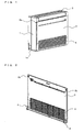
- Fig. 1 is a perspective view illustrating an appearance of a floor-standing indoor unit of an air-conditioning apparatus according to Embodiment.
- Fig. 2 is a perspective view of a design panel of the floor-standing indoor unit illustrated in Fig. 1 that is seen from the back side.
- the floor-standing indoor unit includes a rectangular-parallelpiped casing 1 having an opening in the front face thereof and a base 1a at the bottom thereof, an air outlet 2 provided at the top of the casing 1, an air-sending device and a heat exchanger provided in the casing 1, a design panel 3 covering the opening provided in the front face of the casing 1, an air inlet 4 provided in the design panel 3, and so forth.
- the design panel 3 has catch-receiving portions 5b on two respective sides at the top of the back face thereof. The catch-receiving portions 5b engage with respective catches 5a that are provided on the casing 1.
- the design panel 3 also has panel-supporting portions 6, to be described below, provided on two respective sides at the bottom of the back face thereof.
- the floor-standing indoor unit is connected to an outdoor unit, which is provided outdoor, by a refrigerant pipe.
- the heat exchanger included in the floor-standing indoor unit functions as a condenser in a heating operation and as an evaporator in a cooling operation.
- the air-sending device is activated, and air in the room is taken into the indoor unit through the air inlet 4.
- the air thus taken is made to flow through the heat exchanger, where the air undergoes heat exchange. Consequently, cooling air is blown from the air outlet 2 into the room.
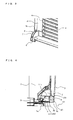
- Fig. 3 is an enlarged perspective view of the design panel 3 according to Embodiment illustrating one of the panel-supporting portions 6.
- Fig. 4 is a sectional view illustrating the panel-supporting portion 6 of the design panel 3 and a corresponding one of receiving cases 9 provided to the casing 1 according to Embodiment.
- each panel-supporting portion 6 is secured to a corresponding one of side frames 3a provided on the right and left sides of the design panel 3 and to a portion of a frame 4a of the air inlet 4 that faces the side frame 3a.
- the panel-supporting portion 6 includes an arm portion 7 having a plate shape, for example, and a shaft member 8 having a cylindrical shape, for example.
- the arm portion 7 projects from the back face of the design panel 3 toward the inner side of the casing 1 and extends obliquely downward.
- the shaft member 8 is provided at the tip of the arm portion 7 and on a side face of the arm portion 7 that faces the air inlet 4.
- the shaft member 8 may have a columnar shape instead of the cylindrical shape.
- the casing 1 also has receiving cases 9 provided on two respective sides at the bottom of the front face thereof.
- the receiving cases 9 receive the respective panel-supporting portions 6.
- the receiving cases 9 each have a box shape with an opening in the front face thereof.
- a guiding portion 10 is provided in the receiving case 9 and extends rearward.
- the guiding portion 10 is a plate having a quadrilateral shape in side view, with an upper side 10a among the four sides thereof being parallel to the bottom surface of the receiving case 9 and another side thereof facing the rear side of the receiving case 9 being formed into an oblique side 10b sloping upward in a direction toward the opening of the receiving case 9.
- the oblique side 10b forms a rail 11 that guides the shaft member 8 of the panel-supporting portion 6 to move in accordance with the angle of tilt of the design panel 3.
- the rail 11 has a rail terminal point 11a where the rail 11 intersects the upper side 10a of the guiding portion 10.
- the rail terminal point 11a is set at such a position that, while the design panel 3 is being tilted, a part 3c (edge) of the design panel 3 that is at a front-face bottom edge (a bottom edge of the front face) of the design panel 3 resides at or above a level where the base 1 a of the casing 1 resides.
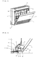
- Fig. 5 is a perspective view of the floor-standing indoor unit illustrated in Fig. 1 with the design panel 3 tilted toward the near side.
- Fig. 6 is a sectional view illustrating a relationship between the panel-supporting portion 6 and the receiving case 9 that is established when the design panel 3 is tilted.
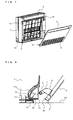
- Fig. 7 is a perspective view of the floor-standing indoor unit with the design panel 3 removed from the casing 1.
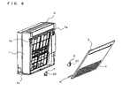
- Fig. 8 is a sectional view illustrating the panel-supporting portion 6 and the receiving case 9 with the design panel 3 removed from the casing 1.
- the shaft members 8 of the panel-supporting portions 6 are locked on the rails 11 of the guiding portions 10 with the lower-frame edge 3b that is in contact with the front-face bottom edge 1 b of the casing 1 functioning as a support. This is because the weight of the design panel 3 that is supported at its center of rotation is applied to the shaft members 8 of the panel-supporting portions 6.
- the shaft members 8 of the panel-supporting portions 6 move upward along the rails 11 of the guiding portions 10 in accordance with the angle of tilt of the design panel 3. Subsequently, as illustrated in Fig. 6 , the shaft members 8 of the panel-supporting portions 6 go over the respective rail terminal points 11a, whereby the design panel 3 is removed from the casing 1 (see Figs. 7 and 8 ).
- the part 3c at the front-face bottom edge of the design panel 3 resides at or above the level where the base 1a of the casing 1 resides (see Fig. 6 ).
- the design panel 3 is removable from the casing 1 in such a manner as to avoid the contact with the floor surface 20.
- each shaft member 8 moves toward and goes over a corresponding one of the rail terminal points 11a forms an arc shape with the lower-frame edge 3b of the design panel 3 that is in contact with the front-face bottom edge 1b of the casing 1 being the center of rotation and the radius of rotation being the distance between the foregoing center of rotation and the center of the shaft member 8, as described above.
- each of the rail terminal points 11a with respect to a corresponding one of the shaft members 8 of the panel-supporting portions 6 is set at such a position that, while the design panel 3 is being tilted, the part 3c at the front-face bottom edge of the design panel 3 resides at or above the level where the base 1a of the casing 1 resides.
- the design panel 3 is removable from the casing 1 in such a manner as to avoid the contact between the part 3c at the front-face bottom edge thereof and the floor surface 20. Therefore, the casing 1 can be provided with the design panel 3 extending over the front-face bottom edge 1b of the casing 1. Accordingly, a floor-standing indoor unit having excellent design is provided.
- the receiving cases 9 having the respective guiding portions 10 are integrally provided to the casing 1 as parts thereof on the two respective sides at the bottom of the front face of the casing 1.
- the receiving cases 9 may be fabricated separately from the casing 1 and may be later attached to the two respective sides at the bottom of the front face of the casing 1.
- the shaft members 8 of the panel-supporting portions 6 are each provided at the tip of a corresponding one of the arm portions 7 and on the side face of the arm portion 7 that faces the air inlet 4.
- each shaft member 8 may be provided on the other side face of the corresponding arm portion 7.
Landscapes
- Engineering & Computer Science (AREA)
- Chemical & Material Sciences (AREA)
- Combustion & Propulsion (AREA)
- Mechanical Engineering (AREA)
- General Engineering & Computer Science (AREA)
- Air Filters, Heat-Exchange Apparatuses, And Housings Of Air-Conditioning Units (AREA)
Applications Claiming Priority (1)
| Application Number | Priority Date | Filing Date | Title |
|---|---|---|---|
| JP2013014764A JP5968238B2 (ja) | 2013-01-29 | 2013-01-29 | 空気調和機の床置き形室内機 |
Publications (2)
| Publication Number | Publication Date |
|---|---|
| EP2759781A1 EP2759781A1 (en) | 2014-07-30 |
| EP2759781B1 true EP2759781B1 (en) | 2015-12-02 |
Family
ID=49513815
Family Applications (1)
| Application Number | Title | Priority Date | Filing Date |
|---|---|---|---|
| EP13190967.3A Not-in-force EP2759781B1 (en) | 2013-01-29 | 2013-10-30 | Floor-standing indoor unit of air-conditioning apparatus |
Country Status (3)
| Country | Link |
|---|---|
| EP (1) | EP2759781B1 (enExample) |
| JP (1) | JP5968238B2 (enExample) |
| CN (1) | CN203595186U (enExample) |
Cited By (1)
| Publication number | Priority date | Publication date | Assignee | Title |
|---|---|---|---|---|
| EP4184065A1 (en) * | 2021-11-18 | 2023-05-24 | Mitsubishi Heavy Industries Thermal Systems, Ltd. | Indoor unit |
Families Citing this family (4)
| Publication number | Priority date | Publication date | Assignee | Title |
|---|---|---|---|---|
| CN105805919A (zh) * | 2016-04-19 | 2016-07-27 | 青岛海尔空调器有限总公司 | 一种立式空调 |
| WO2018154681A1 (ja) * | 2017-02-23 | 2018-08-30 | 三菱電機株式会社 | 空気調和機 |
| CN106871405A (zh) * | 2017-03-30 | 2017-06-20 | 广东美的制冷设备有限公司 | 导风装置、导风控制方法和空调器 |
| MY195538A (en) * | 2018-10-05 | 2023-01-31 | Daikin Res & Development Malaysia Sdn Bhd | A Housing With Hinged Access Panel |
Family Cites Families (5)
| Publication number | Priority date | Publication date | Assignee | Title |
|---|---|---|---|---|
| JPS4727453U (enExample) * | 1971-04-15 | 1972-11-28 | ||
| JP3805285B2 (ja) * | 2002-07-04 | 2006-08-02 | 三菱電機株式会社 | 空気調和機のリモコン収納装置 |
| JP2004239601A (ja) | 2003-01-15 | 2004-08-26 | Sanyo Electric Co Ltd | 壁掛け型空気調和機 |
| WO2007108584A1 (en) * | 2006-03-20 | 2007-09-27 | Lg Electronics, Inc. | Indoor unit for air conditioner |
| JP4698726B2 (ja) * | 2008-12-18 | 2011-06-08 | 三菱電機株式会社 | 床置き形空気調和機 |
-
2013
- 2013-01-29 JP JP2013014764A patent/JP5968238B2/ja not_active Expired - Fee Related
- 2013-10-30 EP EP13190967.3A patent/EP2759781B1/en not_active Not-in-force
- 2013-11-27 CN CN201320761141.6U patent/CN203595186U/zh not_active Expired - Lifetime
Cited By (1)
| Publication number | Priority date | Publication date | Assignee | Title |
|---|---|---|---|---|
| EP4184065A1 (en) * | 2021-11-18 | 2023-05-24 | Mitsubishi Heavy Industries Thermal Systems, Ltd. | Indoor unit |
Also Published As
| Publication number | Publication date |
|---|---|
| JP2014145542A (ja) | 2014-08-14 |
| CN203595186U (zh) | 2014-05-14 |
| JP5968238B2 (ja) | 2016-08-10 |
| EP2759781A1 (en) | 2014-07-30 |
Similar Documents
| Publication | Publication Date | Title |
|---|---|---|
| EP2759781B1 (en) | Floor-standing indoor unit of air-conditioning apparatus | |
| EP2199695B1 (en) | Ceiling mounting type air conditioner | |
| CN103765120B (zh) | 空气调节机 | |
| US9534802B2 (en) | Ventilation device | |
| KR101507163B1 (ko) | 공기 조화기의 실내기 | |
| EP3270074B1 (en) | Ceiling-embedded air conditioner | |
| EP2050365A1 (en) | Showcase | |
| JPWO2019038798A1 (ja) | 天井埋込型空気調和機 | |
| CN105091287A (zh) | 空调机的风向调整装置以及空调机 | |
| ES2367903T3 (es) | Acondicionador de aire. | |
| JP2014145542A5 (enExample) | ||
| KR102789364B1 (ko) | 공기조화기 | |
| KR101611327B1 (ko) | 스텐드형 공기조화기 | |
| JP4265467B2 (ja) | 換気扇 | |
| JP2013148227A (ja) | 風向変更装置及びこれを備えた空気調節装置 | |
| NZ617295B (en) | Floor-standing indoor unit of air-conditioning apparatus | |
| EP1950503A1 (en) | Indoor unit of air conditioner with air inlet via movable front panel and air outlet via bottom/top towards rearside | |
| EP3534085A1 (en) | Indoor unit of air-conditioner | |
| EP3460350A1 (en) | Indoor unit of air-conditioner | |
| KR100600745B1 (ko) | 공기조화기의 실내기 | |
| JP2006239647A (ja) | 除湿機 | |
| JP2007212000A (ja) | 空気調和装置 | |
| KR20240102405A (ko) | 공기조화기의 실내기 | |
| JP6069866B2 (ja) | 空調室内機 | |
| KR20240102397A (ko) | 공기조화기의 실내기 |
Legal Events
| Date | Code | Title | Description |
|---|---|---|---|
| PUAI | Public reference made under article 153(3) epc to a published international application that has entered the european phase |
Free format text: ORIGINAL CODE: 0009012 |
|
| 17P | Request for examination filed |
Effective date: 20140228 |
|
| AK | Designated contracting states |
Kind code of ref document: A1 Designated state(s): AL AT BE BG CH CY CZ DE DK EE ES FI FR GB GR HR HU IE IS IT LI LT LU LV MC MK MT NL NO PL PT RO RS SE SI SK SM TR |
|
| AX | Request for extension of the european patent |
Extension state: BA ME |
|
| GRAP | Despatch of communication of intention to grant a patent |
Free format text: ORIGINAL CODE: EPIDOSNIGR1 |
|
| INTG | Intention to grant announced |
Effective date: 20150519 |
|
| GRAS | Grant fee paid |
Free format text: ORIGINAL CODE: EPIDOSNIGR3 |
|
| GRAA | (expected) grant |
Free format text: ORIGINAL CODE: 0009210 |
|
| AK | Designated contracting states |
Kind code of ref document: B1 Designated state(s): AL AT BE BG CH CY CZ DE DK EE ES FI FR GB GR HR HU IE IS IT LI LT LU LV MC MK MT NL NO PL PT RO RS SE SI SK SM TR |
|
| REG | Reference to a national code |
Ref country code: GB Ref legal event code: FG4D |
|
| REG | Reference to a national code |
Ref country code: AT Ref legal event code: REF Ref document number: 763808 Country of ref document: AT Kind code of ref document: T Effective date: 20151215 Ref country code: CH Ref legal event code: EP |
|
| REG | Reference to a national code |
Ref country code: IE Ref legal event code: FG4D |
|
| REG | Reference to a national code |
Ref country code: DE Ref legal event code: R096 Ref document number: 602013003994 Country of ref document: DE |
|
| REG | Reference to a national code |
Ref country code: NL Ref legal event code: MP Effective date: 20160302 |
|
| REG | Reference to a national code |
Ref country code: LT Ref legal event code: MG4D |
|
| REG | Reference to a national code |
Ref country code: AT Ref legal event code: MK05 Ref document number: 763808 Country of ref document: AT Kind code of ref document: T Effective date: 20151202 |
|
| PG25 | Lapsed in a contracting state [announced via postgrant information from national office to epo] |
Ref country code: LT Free format text: LAPSE BECAUSE OF FAILURE TO SUBMIT A TRANSLATION OF THE DESCRIPTION OR TO PAY THE FEE WITHIN THE PRESCRIBED TIME-LIMIT Effective date: 20151202 Ref country code: ES Free format text: LAPSE BECAUSE OF FAILURE TO SUBMIT A TRANSLATION OF THE DESCRIPTION OR TO PAY THE FEE WITHIN THE PRESCRIBED TIME-LIMIT Effective date: 20151202 Ref country code: NO Free format text: LAPSE BECAUSE OF FAILURE TO SUBMIT A TRANSLATION OF THE DESCRIPTION OR TO PAY THE FEE WITHIN THE PRESCRIBED TIME-LIMIT Effective date: 20160302 |
|
| PG25 | Lapsed in a contracting state [announced via postgrant information from national office to epo] |
Ref country code: AT Free format text: LAPSE BECAUSE OF FAILURE TO SUBMIT A TRANSLATION OF THE DESCRIPTION OR TO PAY THE FEE WITHIN THE PRESCRIBED TIME-LIMIT Effective date: 20151202 Ref country code: FI Free format text: LAPSE BECAUSE OF FAILURE TO SUBMIT A TRANSLATION OF THE DESCRIPTION OR TO PAY THE FEE WITHIN THE PRESCRIBED TIME-LIMIT Effective date: 20151202 Ref country code: NL Free format text: LAPSE BECAUSE OF FAILURE TO SUBMIT A TRANSLATION OF THE DESCRIPTION OR TO PAY THE FEE WITHIN THE PRESCRIBED TIME-LIMIT Effective date: 20151202 Ref country code: PL Free format text: LAPSE BECAUSE OF FAILURE TO SUBMIT A TRANSLATION OF THE DESCRIPTION OR TO PAY THE FEE WITHIN THE PRESCRIBED TIME-LIMIT Effective date: 20151202 Ref country code: GR Free format text: LAPSE BECAUSE OF FAILURE TO SUBMIT A TRANSLATION OF THE DESCRIPTION OR TO PAY THE FEE WITHIN THE PRESCRIBED TIME-LIMIT Effective date: 20160303 Ref country code: RS Free format text: LAPSE BECAUSE OF FAILURE TO SUBMIT A TRANSLATION OF THE DESCRIPTION OR TO PAY THE FEE WITHIN THE PRESCRIBED TIME-LIMIT Effective date: 20151202 Ref country code: SE Free format text: LAPSE BECAUSE OF FAILURE TO SUBMIT A TRANSLATION OF THE DESCRIPTION OR TO PAY THE FEE WITHIN THE PRESCRIBED TIME-LIMIT Effective date: 20151202 Ref country code: LV Free format text: LAPSE BECAUSE OF FAILURE TO SUBMIT A TRANSLATION OF THE DESCRIPTION OR TO PAY THE FEE WITHIN THE PRESCRIBED TIME-LIMIT Effective date: 20151202 |
|
| PG25 | Lapsed in a contracting state [announced via postgrant information from national office to epo] |
Ref country code: IS Free format text: LAPSE BECAUSE OF FAILURE TO SUBMIT A TRANSLATION OF THE DESCRIPTION OR TO PAY THE FEE WITHIN THE PRESCRIBED TIME-LIMIT Effective date: 20151202 |
|
| PG25 | Lapsed in a contracting state [announced via postgrant information from national office to epo] |
Ref country code: CZ Free format text: LAPSE BECAUSE OF FAILURE TO SUBMIT A TRANSLATION OF THE DESCRIPTION OR TO PAY THE FEE WITHIN THE PRESCRIBED TIME-LIMIT Effective date: 20151202 |
|
| PG25 | Lapsed in a contracting state [announced via postgrant information from national office to epo] |
Ref country code: EE Free format text: LAPSE BECAUSE OF FAILURE TO SUBMIT A TRANSLATION OF THE DESCRIPTION OR TO PAY THE FEE WITHIN THE PRESCRIBED TIME-LIMIT Effective date: 20151202 Ref country code: PT Free format text: LAPSE BECAUSE OF FAILURE TO SUBMIT A TRANSLATION OF THE DESCRIPTION OR TO PAY THE FEE WITHIN THE PRESCRIBED TIME-LIMIT Effective date: 20160404 Ref country code: SK Free format text: LAPSE BECAUSE OF FAILURE TO SUBMIT A TRANSLATION OF THE DESCRIPTION OR TO PAY THE FEE WITHIN THE PRESCRIBED TIME-LIMIT Effective date: 20151202 Ref country code: SM Free format text: LAPSE BECAUSE OF FAILURE TO SUBMIT A TRANSLATION OF THE DESCRIPTION OR TO PAY THE FEE WITHIN THE PRESCRIBED TIME-LIMIT Effective date: 20151202 Ref country code: RO Free format text: LAPSE BECAUSE OF FAILURE TO SUBMIT A TRANSLATION OF THE DESCRIPTION OR TO PAY THE FEE WITHIN THE PRESCRIBED TIME-LIMIT Effective date: 20151202 Ref country code: IS Free format text: LAPSE BECAUSE OF FAILURE TO SUBMIT A TRANSLATION OF THE DESCRIPTION OR TO PAY THE FEE WITHIN THE PRESCRIBED TIME-LIMIT Effective date: 20160402 |
|
| REG | Reference to a national code |
Ref country code: DE Ref legal event code: R097 Ref document number: 602013003994 Country of ref document: DE |
|
| PLBE | No opposition filed within time limit |
Free format text: ORIGINAL CODE: 0009261 |
|
| STAA | Information on the status of an ep patent application or granted ep patent |
Free format text: STATUS: NO OPPOSITION FILED WITHIN TIME LIMIT |
|
| PG25 | Lapsed in a contracting state [announced via postgrant information from national office to epo] |
Ref country code: DK Free format text: LAPSE BECAUSE OF FAILURE TO SUBMIT A TRANSLATION OF THE DESCRIPTION OR TO PAY THE FEE WITHIN THE PRESCRIBED TIME-LIMIT Effective date: 20151202 |
|
| 26N | No opposition filed |
Effective date: 20160905 |
|
| PG25 | Lapsed in a contracting state [announced via postgrant information from national office to epo] |
Ref country code: SI Free format text: LAPSE BECAUSE OF FAILURE TO SUBMIT A TRANSLATION OF THE DESCRIPTION OR TO PAY THE FEE WITHIN THE PRESCRIBED TIME-LIMIT Effective date: 20151202 |
|
| PG25 | Lapsed in a contracting state [announced via postgrant information from national office to epo] |
Ref country code: BE Free format text: LAPSE BECAUSE OF FAILURE TO SUBMIT A TRANSLATION OF THE DESCRIPTION OR TO PAY THE FEE WITHIN THE PRESCRIBED TIME-LIMIT Effective date: 20151202 |
|
| REG | Reference to a national code |
Ref country code: DE Ref legal event code: R119 Ref document number: 602013003994 Country of ref document: DE |
|
| REG | Reference to a national code |
Ref country code: CH Ref legal event code: PL |
|
| PG25 | Lapsed in a contracting state [announced via postgrant information from national office to epo] |
Ref country code: MC Free format text: LAPSE BECAUSE OF FAILURE TO SUBMIT A TRANSLATION OF THE DESCRIPTION OR TO PAY THE FEE WITHIN THE PRESCRIBED TIME-LIMIT Effective date: 20151202 |
|
| REG | Reference to a national code |
Ref country code: IE Ref legal event code: MM4A |
|
| REG | Reference to a national code |
Ref country code: FR Ref legal event code: ST Effective date: 20170630 |
|
| PG25 | Lapsed in a contracting state [announced via postgrant information from national office to epo] |
Ref country code: FR Free format text: LAPSE BECAUSE OF NON-PAYMENT OF DUE FEES Effective date: 20161102 Ref country code: DE Free format text: LAPSE BECAUSE OF NON-PAYMENT OF DUE FEES Effective date: 20170503 Ref country code: CH Free format text: LAPSE BECAUSE OF NON-PAYMENT OF DUE FEES Effective date: 20161031 Ref country code: LI Free format text: LAPSE BECAUSE OF NON-PAYMENT OF DUE FEES Effective date: 20161031 |
|
| PG25 | Lapsed in a contracting state [announced via postgrant information from national office to epo] |
Ref country code: LU Free format text: LAPSE BECAUSE OF NON-PAYMENT OF DUE FEES Effective date: 20161030 |
|
| PG25 | Lapsed in a contracting state [announced via postgrant information from national office to epo] |
Ref country code: IE Free format text: LAPSE BECAUSE OF NON-PAYMENT OF DUE FEES Effective date: 20161030 |
|
| PG25 | Lapsed in a contracting state [announced via postgrant information from national office to epo] |
Ref country code: HU Free format text: LAPSE BECAUSE OF FAILURE TO SUBMIT A TRANSLATION OF THE DESCRIPTION OR TO PAY THE FEE WITHIN THE PRESCRIBED TIME-LIMIT; INVALID AB INITIO Effective date: 20131030 |
|
| GBPC | Gb: european patent ceased through non-payment of renewal fee |
Effective date: 20171030 |
|
| PG25 | Lapsed in a contracting state [announced via postgrant information from national office to epo] |
Ref country code: CY Free format text: LAPSE BECAUSE OF FAILURE TO SUBMIT A TRANSLATION OF THE DESCRIPTION OR TO PAY THE FEE WITHIN THE PRESCRIBED TIME-LIMIT Effective date: 20151202 Ref country code: MK Free format text: LAPSE BECAUSE OF FAILURE TO SUBMIT A TRANSLATION OF THE DESCRIPTION OR TO PAY THE FEE WITHIN THE PRESCRIBED TIME-LIMIT Effective date: 20151202 Ref country code: MT Free format text: LAPSE BECAUSE OF NON-PAYMENT OF DUE FEES Effective date: 20161031 Ref country code: HR Free format text: LAPSE BECAUSE OF FAILURE TO SUBMIT A TRANSLATION OF THE DESCRIPTION OR TO PAY THE FEE WITHIN THE PRESCRIBED TIME-LIMIT Effective date: 20151202 |
|
| PG25 | Lapsed in a contracting state [announced via postgrant information from national office to epo] |
Ref country code: GB Free format text: LAPSE BECAUSE OF NON-PAYMENT OF DUE FEES Effective date: 20171030 Ref country code: BG Free format text: LAPSE BECAUSE OF FAILURE TO SUBMIT A TRANSLATION OF THE DESCRIPTION OR TO PAY THE FEE WITHIN THE PRESCRIBED TIME-LIMIT Effective date: 20151202 |
|
| PG25 | Lapsed in a contracting state [announced via postgrant information from national office to epo] |
Ref country code: TR Free format text: LAPSE BECAUSE OF FAILURE TO SUBMIT A TRANSLATION OF THE DESCRIPTION OR TO PAY THE FEE WITHIN THE PRESCRIBED TIME-LIMIT Effective date: 20151202 Ref country code: AL Free format text: LAPSE BECAUSE OF FAILURE TO SUBMIT A TRANSLATION OF THE DESCRIPTION OR TO PAY THE FEE WITHIN THE PRESCRIBED TIME-LIMIT Effective date: 20151202 |
|
| P01 | Opt-out of the competence of the unified patent court (upc) registered |
Effective date: 20230512 |
|
| PGFP | Annual fee paid to national office [announced via postgrant information from national office to epo] |
Ref country code: IT Payment date: 20230913 Year of fee payment: 11 |
|
| PG25 | Lapsed in a contracting state [announced via postgrant information from national office to epo] |
Ref country code: IT Free format text: LAPSE BECAUSE OF NON-PAYMENT OF DUE FEES Effective date: 20241030 |