EP2759446A1 - Elektrisch rotatorische Verstelleinheit, insbesondere für indirekte Sichtsysteme für Fahrzeuge - Google Patents
Elektrisch rotatorische Verstelleinheit, insbesondere für indirekte Sichtsysteme für Fahrzeuge Download PDFInfo
- Publication number
- EP2759446A1 EP2759446A1 EP20140152778 EP14152778A EP2759446A1 EP 2759446 A1 EP2759446 A1 EP 2759446A1 EP 20140152778 EP20140152778 EP 20140152778 EP 14152778 A EP14152778 A EP 14152778A EP 2759446 A1 EP2759446 A1 EP 2759446A1
- Authority
- EP
- European Patent Office
- Prior art keywords
- unit according
- electric rotary
- adjustment unit
- coupling elements
- rotated
- Prior art date
- Legal status (The legal status is an assumption and is not a legal conclusion. Google has not performed a legal analysis and makes no representation as to the accuracy of the status listed.)
- Granted
Links
Images



Classifications
-
- B—PERFORMING OPERATIONS; TRANSPORTING
- B60—VEHICLES IN GENERAL
- B60R—VEHICLES, VEHICLE FITTINGS, OR VEHICLE PARTS, NOT OTHERWISE PROVIDED FOR
- B60R1/00—Optical viewing arrangements; Real-time viewing arrangements for drivers or passengers using optical image capturing systems, e.g. cameras or video systems specially adapted for use in or on vehicles
- B60R1/02—Rear-view mirror arrangements
- B60R1/06—Rear-view mirror arrangements mounted on vehicle exterior
- B60R1/062—Rear-view mirror arrangements mounted on vehicle exterior with remote control for adjusting position
- B60R1/07—Rear-view mirror arrangements mounted on vehicle exterior with remote control for adjusting position by electrically powered actuators
- B60R1/072—Rear-view mirror arrangements mounted on vehicle exterior with remote control for adjusting position by electrically powered actuators for adjusting the mirror relative to its housing
-
- B—PERFORMING OPERATIONS; TRANSPORTING
- B60—VEHICLES IN GENERAL
- B60R—VEHICLES, VEHICLE FITTINGS, OR VEHICLE PARTS, NOT OTHERWISE PROVIDED FOR
- B60R1/00—Optical viewing arrangements; Real-time viewing arrangements for drivers or passengers using optical image capturing systems, e.g. cameras or video systems specially adapted for use in or on vehicles
- B60R1/02—Rear-view mirror arrangements
- B60R1/06—Rear-view mirror arrangements mounted on vehicle exterior
- B60R1/062—Rear-view mirror arrangements mounted on vehicle exterior with remote control for adjusting position
- B60R1/07—Rear-view mirror arrangements mounted on vehicle exterior with remote control for adjusting position by electrically powered actuators
- B60R1/074—Rear-view mirror arrangements mounted on vehicle exterior with remote control for adjusting position by electrically powered actuators for retracting the mirror arrangements to a non-use position alongside the vehicle
-
- F—MECHANICAL ENGINEERING; LIGHTING; HEATING; WEAPONS; BLASTING
- F16—ENGINEERING ELEMENTS AND UNITS; GENERAL MEASURES FOR PRODUCING AND MAINTAINING EFFECTIVE FUNCTIONING OF MACHINES OR INSTALLATIONS; THERMAL INSULATION IN GENERAL
- F16D—COUPLINGS FOR TRANSMITTING ROTATION; CLUTCHES; BRAKES
- F16D11/00—Clutches in which the members have interengaging parts
- F16D11/14—Clutches in which the members have interengaging parts with clutching members movable only axially
-
- F—MECHANICAL ENGINEERING; LIGHTING; HEATING; WEAPONS; BLASTING
- F16—ENGINEERING ELEMENTS AND UNITS; GENERAL MEASURES FOR PRODUCING AND MAINTAINING EFFECTIVE FUNCTIONING OF MACHINES OR INSTALLATIONS; THERMAL INSULATION IN GENERAL
- F16D—COUPLINGS FOR TRANSMITTING ROTATION; CLUTCHES; BRAKES
- F16D28/00—Electrically-actuated clutches
-
- F—MECHANICAL ENGINEERING; LIGHTING; HEATING; WEAPONS; BLASTING
- F16—ENGINEERING ELEMENTS AND UNITS; GENERAL MEASURES FOR PRODUCING AND MAINTAINING EFFECTIVE FUNCTIONING OF MACHINES OR INSTALLATIONS; THERMAL INSULATION IN GENERAL
- F16D—COUPLINGS FOR TRANSMITTING ROTATION; CLUTCHES; BRAKES
- F16D7/00—Slip couplings, e.g. slipping on overload, for absorbing shock
- F16D7/04—Slip couplings, e.g. slipping on overload, for absorbing shock of the ratchet type
-
- H—ELECTRICITY
- H02—GENERATION; CONVERSION OR DISTRIBUTION OF ELECTRIC POWER
- H02K—DYNAMO-ELECTRIC MACHINES
- H02K7/00—Arrangements for handling mechanical energy structurally associated with dynamo-electric machines, e.g. structural association with mechanical driving motors or auxiliary dynamo-electric machines
- H02K7/14—Structural association with mechanical loads, e.g. with hand-held machine tools or fans
Definitions
- the invention relates to an electrically rotary adjustment unit, in particular for indirect vision systems for vehicles according to the preamble of claim 1.
- Electrically rotary adjustment units for folding and / or adjusting of indirect vision systems on vehicles, for example, from EP 1 755 923 B1 , of the DE 199 53 484 C2 and the EP 2 436 559 A1 known.
- the electric rotary drive is arranged between a base part and a part to be rotated, so that the electric rotary drive must be designed for the transmission and reception of forces and moments acting between the base part and the rotating part. Consequently, comparatively large and heavy components result and thus a comparatively large and heavy electrically rotary adjustment unit.
- the electric rotary drive is activated only for a short time or for a period of time during which care can be taken that no excessive forces act on the base part and the rotating part. Consequently, the electric rotary drive can be designed correspondingly small and for comparatively small forces and moments.
- the coupling device comprises first coupling elements and at least one decoupling element, which is arranged on the part to be rotated.
- Associated second coupling elements are provided on the base part, wherein the first and second coupling elements are in engagement with one another when the base part and the rotating part are coupled.
- the output member has a Geoetrie, which causes the two coupling elements are separated from each other upon actuation of the electric rotary drive, so that the base part and rotating part are decoupled from each other.
- the at least one decoupling element is a decoupling pin and the at least one driver element is a driving pin.
- the uncoupling pins slide along the inclined sections and thus push the driven part and the part to be twisted apart in the axial direction, so that the two coupling elements are separated from each other and the base part and part to be rotated are decoupled from each other.
- a V-shaped groove is also conceivable in which a decoupling pin with a hemispherical end slides along and thus increases the distance between the driven part and the rotating part and separates the two coupling elements from one another.
- the coupling between the base part and rotating part is maintained in the neutral position and the decoupling upon activation of the electric rotary drive can only be done against the resistance of the spring element or the elastic element.
- Claim 5 has an advantageous and simple embodiment of the two coupling elements in the form of a dog clutch to the object.
- the annular configuration of the output element according to claim 6 lends itself to rotational movements in an advantageous manner.
- the engagement and disengagement of the two coupling elements is supported. Due to the oblique flanks of the trapezoidal coupling elements, the decoupling elements slide more easily into each other or apart.
- the advantageous embodiment of the invention according to claim 13 defines the maximum angle of rotation, i. the angle at the e.g. a mirror is completely folded.
- the achievement of this maximum angle of rotation or of the stop is detected by monitoring the current absorbed by the electric rotary drive current. Upon reaching the stop, the current increases and this can be detected by a sensor and control device. If this is the case, the direction of rotation is reversed briefly, so that the two coupling elements can be engaged again.
- the first and second coupling elements are designed so that only when rotated by a certain angle, the coupling elements can interlock again. As a result, a minimum angle of rotation between two zero positions is determined.
- Due to the advantageous embodiment of the invention according to claim 23 is allowed that the device automatically gets into the Abklappwolf when exposed to excessive forces, for example, in collision with an obstacle.
- a rotary electric drive and a stepper motor can be used, which drives the driven part directly or via a transmission.
- the stepper motor can be placed directly in the tubular base part instead of the transmission.
- Fig. 1 shown exploded view of the first embodiment of the invention comprises a base part 1 and a part to be rotated 3, which is rotatably mounted on an axle 5.
- the axle 5 is mounted in the base part 1.
- the base part 1 is connected to an electric rotary drive 7, which comprises a Wolfrom gear 9 that is penetrated by the axle 5.
- the Wolfrom gearbox 9 drives a ring-shaped output element 11.
- the tubular base part 1 comprises a first open end 13 and an opposite second open end 15.
- Axially facing first coupling elements 17 are arranged at the first open end 13 and configured in the form of protrusions or teeth of a first width 18 and a second width 19 are.
- the number of coupling elements of the first width 18 is greater than the number of coupling elements of the second width 19.
- three first coupling elements of the second width 19 are provided, which are distributed symmetrically over the circumference of the first open end 13. Between the first coupling elements of the second width 19 four coupling elements of the first width 18 are arranged on the circumference of the first open end 13 of the base part 1 - see Fig. 5 ,
- the part 3 to be rotated comprises a first rotary element 21 having the second coupling element 23, which are formed complementary to the first coupling elements 17. That is, the second coupling elements 23 have recesses of first width 24, which serve to receive the first coupling elements first width 18, and recesses second width 25, which serve to receive the second coupling elements 19 second width.
- first coupling elements 17 on the base part 1 and associated complementary second coupling elements 23 on the first rotating elements 21 of the rotating part 3 engage only at three specific angular positions or three specific rotational positions and thus base part 1 and rotatably coupled to rotate part 3 with each other.
- the first rotary element 21 also includes three uncoupling pins 27, which are offset radially inwardly and axially forwards relative to the second coupling elements 23.
- the three uncoupling pins 27 are arranged distributed symmetrically over the edge of the first rotary member 21 and extend axially away from it.
- an annular detent surface 29 is provided which engages with an associated counter-latching surface 31 on a second rotary member 33.
- the electric rotary drive 7 comprises an electric motor 35 with drive worm 36.
- the Wolfrom gear 9 comprises a central sun gear 43 which is non-rotatably connected to a central worm wheel 41.
- the Wolfrom gear 9 is driven by the drive worm 36, which engages the worm wheel 41.
- the central sun gear 43 drives three associated planetary gears 45, which in turn engage in a respect to the base member 1 stationary ring gear 47 and in an internal toothing in the driven part 11.
- the Wolfrom gear 9 is arranged on the tubular base part 1.
- the electric motor 35 with drive worm 36 is arranged transversely to the base part 1 and the drive worm 36 engages via an opening in the base part 1 into the worm wheel 41. Covering elements 49, the electric motor 35 and the drive screw 36 is covered and protected against the weather.
- the annular output member 11 has, as mentioned, an internal toothing, in which the planet gears 45 of the Wolfrom gear 9 engage.
- the output member 11 comprises a first edge 51 and an opposite second edge 53.
- On the first edge 51 symmetrically distributed over the circumference three driving pins 55 are formed, which extend in the axial direction of the first edge 51 away and the first rotary member 21 with the Disconnecting pin 27 facing.
- a lower plateau surface 57 is in each case arranged on the left and on the right, followed by two inclined surfaces 59 and, in turn, followed by two upper plateau surfaces 61.
- the two upper plateau surfaces 61 terminate on the left and right sides on the flanks of the driving pins 55.
- the uncoupling pins 27 slide on rotation of the driven part 11 by the electric rotary drive 7 on the lower plateau surfaces 57 to the inclined surfaces 59 and reach on the upper plateau surfaces 61 in contact with the flanks of the driving pins 55th
- the Wolfrom gear 9, the driven part 11 and the largest part of the first rotary member 21 are arranged in the interior of the tubular base part 1.
- the individual components are braced against each other via the axle element 5 and an elastic element acting on the base part 1 in the form of a spiral spring 63.
- the driven part 11 is in this case mounted rotatably in the interior of the base part 1 via a bearing ring 65.
- the Wolfrom gear 9 is self-locking, ie in the de-energized state, the planet gears remain 45 and do not turn further.
- Fig. 6 shows the current consumption of the electric motor 35 as a function of the rotation angle ⁇ of the electric motor 35 and the output member 11 is the maximum rotation angle ⁇ by a mechanical stop - not shown - set and fixed.
- the base part 1 and the first rotary part 3 are connected to one another in a rotationally fixed manner via the two coupling elements 17 and 23. If the electric rotary drive 7 is activated, the uncoupling pins 27 first grind onto the lower plateau surfaces 57 of the driven part 11 - phase (1) in FIG Fig.
- the first and second coupling elements 17, 23 engage again, so that the base part 1 and the part 3 to be rotated are again coupled to one another in a rotationally fixed manner.
- the electric rotary drive 7 is deactivated and is mechanically decoupled from the part 3 to be rotated - zero position.
- the second embodiment differs from the structure essentially only by the configuration of the driven part 110, in which with respect to the driven part 11 of the first embodiment no upper plateau surfaces 61 are provided, ie the inclined surfaces 59 terminate directly on the flanks of the driving pin 55.
- that Gear designed as a non-self-locking gear ie the gear can be rotated in the de-energized state.
- Fig. 8 shows analogously to Fig. 6 In the zero position, ie with non-active electric rotary drive 7, the base part 1 and the first rotary member 3 via the two coupling elements 17 and 23 are rotatably connected to each other. If the electric rotary drive 7 is activated, the uncoupling pins 27 first grind onto the lower plateau surfaces 57 of the driven part 11 - phase (1) in FIG Fig.
- phase (2) Thereafter slide the uncoupling pin 27 in phase (2) along the inclined surfaces 59 and press the part to be rotated 3 and the output member 11 axially apart and thus solve the first coupling elements 17 of the second Coupling elements 23.
- the decoupling pins 27 come into abutment with the driving pins 55 on the driven element 11.
- the rotation of the driven part 11 is transmitted via the driving pins 55 to the uncoupling pins 27 and thus to the first rotary element 21 and the part to be rotated 3.
- the rotation is done, for example, the folding of a mirror - phase (3).
- phase (3) the free ends of the two decoupling elements 17 and 23 slide along each other.
Landscapes
- Engineering & Computer Science (AREA)
- Mechanical Engineering (AREA)
- General Engineering & Computer Science (AREA)
- Multimedia (AREA)
- Power Engineering (AREA)
- Physics & Mathematics (AREA)
- Electromagnetism (AREA)
- Rear-View Mirror Devices That Are Mounted On The Exterior Of The Vehicle (AREA)
- Mechanical Operated Clutches (AREA)
- Retarders (AREA)
- One-Way And Automatic Clutches, And Combinations Of Different Clutches (AREA)
Abstract
Description
- Die Erfindung betrifft eine elektrisch rotatorische Verstelleinheit, insbesondere für indirekte Sichtsysteme für Fahrzeuge gemäß dem Oberbegriff des Anspruchs 1.
- Elektrisch rotatorische Verstelleinheiten zum Einklappen und/oder Verstellen von indirekten Sichtsystemen an Fahrzeugen sind beispielsweise aus der
EP 1 755 923 B1 , derDE 199 53 484 C2 und derEP 2 436 559 A1 bekannt. Bei diesen Verstelleinheiten ist der elektrische Drehantrieb zwischen einem Basisteil und einem zu drehenden Teil angeordnet, so dass der elektrische Drehantrieb für die Übertragung und Aufnahme der zwischen Basisteil und zu drehendem Teil wirkenden Kräfte und Momente ausgelegt werden muss. Folglich ergeben sich vergleichsweise große und schwere Komponenten und damit eine vergleichsweise große und schwere elektrisch rotatorische Verstelleinheit. - Es ist daher Aufgabe der vorliegenden Erfindung eine elektrisch rotatorische Verstelleinheit, insbesondere für indirekte Sichtsysteme von Fahrzeugen anzugeben, die klein erbaut und leichtere Komponenten ermöglicht.
- Die Lösung dieser Aufgabe erfolgt durch die Merkmale des Anspruchs 1.
- Durch das Vorsehen einer Kupplungsvorrichtung, die in Nullstellung, bei der der elektrische Drehantrieb desaktiviert ist, Basisteil und zu drehendes Teil drehfest miteinander koppelt und dem elektrischen Drehantrieb von dem zu drehenden Teil entkoppelt und bei Aktivierung des elektrischen Drehantrieb Basisteil und zu drehendes Teil voneinander entkoppelt und den elektrischen Drehantrieb mit dem zu drehenden Teil koppelt wird erreicht, dass die im Einsatz auftretenden Kräfte und Momente direkt zwischen Basisteil und zu drehendem Teil über die Kupplungsvorrichtung übertragen werden. Diese direkte und unmittelbare Kopplung zwischen Basisteil und zu drehendem Teil wird nur dann aufgehoben, wenn der elektrische Drehantrieb zum Beispiel zum Abklappen eines Spiegels in eine Parkposition aktiviert wird. Der elektrische Drehantrieb wird nur für kurze Zeit oder für eine Zeitdauer aktiviert, während der dafür Sorge getragen werden kann, dass keine übergroßen Kräfte auf Basisteil und zu drehendes Teil einwirken. Folglich kann der elektrische Drehantrieb entsprechend klein und für vergleichsweise geringe Kräfte und Momente ausgelegt werden.
- Gemäß der vorteilhaften Ausgestaltung der Erfindung nach Anspruch 2 umfasst die Kupplungsvorrichtung erste Kupplungselemente sowie wenigstens ein Entkupplungselement, das an dem zu drehenden Teil angeordnet ist. An dem Basisteil sind zugeordnete zweite Kupplungselemente vorgesehen, wobei die ersten und zweiten Kupplungselemente bei Kopplung von Basisteil und zu drehendem Teil miteinander in Eingriff stehen. Das Abtriebteil weist eine Geoetrie auf, die bewirkt, das bei Betätigung des elektrischen Drehantriebs die beiden Kupplungselemente voneinander getrennt werden, so dass Basisteil und zu drehendes Teil voneinander entkoppelt werden.
- Gemäß der vorteilhaften Ausgestaltung der Erfindung nach Anspruch 3 ist das wenigstens eine Entkupplungselement eine Entkupplungszapfen und das wenigstens eine Mitnehmerelement ist ein Mitnehmerzapfen. Bei Betätigung des elektrischen Drehantriebs gleiten die Entkupplungszapfen an den schrägverlaufenden Abschnitten entlang und drücken damit Abtriebteil und zu verdrehendes Teil in axialer Richtung auseinander, so dass die beiden Kupplungselemente voneinander getrennt und Basisteil und zu drehendes Teil voneinander entkoppelt werden. Anstelle von schräg verlaufenden Abschnitten ist auch eine V-förmig verlaufende Nut denkbar in der ein Entkuppflungszapfen mit halbkugelförmigem Ende entlang gleitet und so den Abstand zwischen Abtriebteil und zu drehendem Teil vergrößert und die beiden Kupplungselement voneinander trennt.
- Durch die vorteilhafte Ausgestaltung der Erfindung nach Anspruch 4 wird in der Nullstellung die Kopplung zwischen Basisteil und zu drehendem Teil aufrechterhalten und die Entkopplung bei Aktivierung des elektrischen Drehantriebs kann nur gegen den Widerstand des Federelements bzw. des elastischen Elements erfolgen.
- Anspruch 5 hat eine vorteilhafte und einfache Ausgestaltung der beiden Kupplungselemente in Form einer Klauenkupplung zum Gegenstand.
- Die ringförmige Ausgestaltung des Abtriebselements gemäß Anspruch 6 bietet sich für Drehbewegungen in vorteilhafter Weise an.
- Durch die vorteilhafte Ausgestaltung der Erfindung nach Anspruch 7 mit einer Mehrzahl von , vorzugsweise drei, Mitnehmerzapfen und einer Mehrzahl von schräg verlaufenden Abschnitten wird eine stabile Konstruktion ermöglicht, bei der keine Kippmomente auftreten. Dies gilt insbesondere dann, wenn jedem Mitnehmerzapfen an dem Abtriebteil ein Entkupplungszapfen an dem zu drehenden Teil zugeordnet ist.
- Durch die vorteilhafte Ausgestaltung der Erfindung nach Anspruch 8 wird erreicht, dass die einzelnen Komponenten mit geringeren Fertigungstolleranzen gefertigt werden müssen. Durch die Plateaufläche bewegt sich das Abtriebteil erst um einen kleinen Winkel bevor der Entkopplungszapfen der schräg verlaufenden Abschnitt erreicht wird und der Entkopplungsvorgang beginnt.
- Durch die vorteilhafte Ausgestaltung der Erfindung nach Anspruch 9 wird es möglich, dass bei Desaktivierung des elektrischen Drehantriebs der Entkopplungszapfen an der Schrägfläche durch die Federkraft des elastischen Elements wieder nach unten gleitet und die beiden Kupplungselemente selbsttätig wieder in Eingriff gelangen. Somit gelangt die Verstelleinheit selbsttätig wieder in Nullstellung, d.h. Basisteil und zu drehender Teil sind miteinander drehfest gekoppelt.
- Durch die vorteilhafte Ausgestaltung der Erfindung nach Anspruch 10 ein zur Verstellung z. B. eines Spiegels ausreichendes Drehmoment zur Verfügung gestellt und gleichzeitig wird ein geringes Bauvolumen ermöglicht. Zudem kann auf vorhandene gängige Komponenten - Wolfrom-Planetengetriebe - zurückgegriffen werden.
- Durch die vorteilhafte Ausgestaltung der Erfindung nach Anspruch 11 wird ermöglicht, dass bei Desaktivierung des elektrischen Antriebs die beiden Kupplungselemente durch das elastische Element wieder in Eingriff gelangen.
- Durch die vorteilhafte Ausgestaltung der Erfindung nach Anspruch 12 wird das Ein- und Auskuppeln der beiden Kupplungselemente unterstützt. Durch die schrägen Flanken der trapezförmigen Kupplungselemente gleiten die Entkupplungselemente leichter ineinander oder auseinander.
- Durch die vorteilhafte Ausgestaltung der Erfindung nach Anspruch 13 wird der maximale Drehwinkel definiert, d.h. der Winkel bei dem z.B. ein Spiegel vollständig eingeklappt ist.
- Durch die vorteilhafte Ausgestaltung der Erfindung nach Anspruch 14 wird die Erreichung dieses maximalen Drehwinkels bzw. des Anschlags durch die Überwachung der von dem elektrischen Drehantrieb aufgenommenen Stromstärke detektiert. Bei Erreichen des Anschlags steigt die Stromstärke an und dies kann durch eine Sensor- und Steuervorrichtung erfasst werden. Ist dies der Fall, wird die Drehrichtung kurz umgedreht, so dass die beiden Kupplungselemente wieder in Eingriff gelangen können.
- Durch die vorteilhaften Ausgestaltungen der Erfindung nach Anspruch 15 sind die ersten und zweiten Kupplungselemente so ausgelegt, dass erst bei Verdrehung um einen bestimmten Winkel die Kupplungselemente wieder ineinandergreifen können. Hierdurch wird ein minimaler Verdrehwinkel zwischen zwei Nullstellungen festgelegt.
- Gemäß der vorteilhaften Ausgestaltung der Erfindung nach den Ansprüchen 16 und 17 wird das Erreichen dieses bestimmten Winkels Ψ dadurch erfasst, dass die verringerte Stromaufnahme des elektrischen Drehantriebs bei Erreichen der Stellung bei der die Kupplungselemente wieder ineinander eingreifen können, erfasst wird.
- Die vorteilhafte Ausgestaltung der Erfindung nach den Ansprüchen Anspruch 18 bis 22 ergibt sich eine einfache Montage und eine kompakte Bauform.
- Durch die vorteilhafte Ausgestaltung der Erfindung nach Anspruch 23 wird ermöglicht, dass die Vorrichtung bei Einwirkung von übermäßigen Kräften z.B. bei Kollision mit einem Hindernis selbsttätig in die Abklappstellung gelangt.
- Als elektrischer Drehantrieb kann auch ein Schrittmotor verwendet werden, der das Abtriebteil direkt oder auch über ein Getriebe antreibt. Bei direktem Antrieb ohne Getriebe, kann der Schrittmotor anstelle des Getriebes direkt in dem rohrförmigen Basisteil angeordnet werden.
- Weitere Einzelheiten, Merkmale und Vorteile der Erfindung ergeben sich aus der nachfolgenden Beschreibung bevorzugter Ausführungsformen anhand der Zeichnungen.
- Es zeigt:
-
Fig. 1 eine Explosionsdarstellung einer beispielhaften ersten Ausführungsform der Erfindung, -
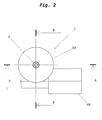
Fig. 2 zeigt eine Aufsicht auf die erste Ausführungsform der Erfindung, -
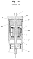
Fig. 3a einen Schnitt entlang A-A inFig. 2 in gekoppeltem Zustand (Nullstellung), -
Fig. 3b einen Schnitt entlang A-A in entkoppelten Zustand (elektrischer Drehantrieb aktiv), -
Fig. 4 einen Schnitt entlang B-B inFig. 2 , -
Fig. 5 zeigt eine perspektivische Darstellung der ersten und zweiten Kupplungselemente der ersten Ausführungsform, -
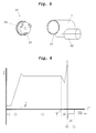
Fig. 6 zeigt die Stromaufnahme des elektrischen Drehantriebs als Funktion des Drehwinkels bei einem selbsthemmenden Getriebe und einem Abtriebteil gemäßFig. 1 , -
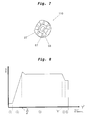
Fig. 7 zeigt eine alternative Ausgestaltung des Abtriebteils gemäß einer zweiten Ausführungsform der Erfindung für eine selbsttätige Kopplung von Basisteil und zu drehendem Teil aufgrund einer Federvorspannung, und -
Fig. 8 zeigt die Stromaufnahme des elektrischen Drehantriebs als Funktion des Drehwinkels bei einem nicht selbsthemmenden Getriebe mit einem Abtriebteil gemäßFig. 7 . - Die in
Fig. 1 gezeigte Explosionsdarstellung der ersten Ausführungsform der Erfindung umfasst ein Basisteil 1 und ein zu drehendes Teil 3, das auf einem Achselement 5 drehbar angeordnet ist. Das Achselement 5 ist in dem Basisteil 1 gelagert. Das Basisteil 1 ist mit einem elektrischen Drehantrieb 7 verbunden, der ein Wolfrom-Getriebe 9 umfasst, dass von dem Achselement 5 durchsetzt wird. Das Wolfrom-Getriebe 9 treibt ein ringförmig ausgestaltetes Abtriebselement 11 an. - Das rohrförmige Basisteil 1 umfasst ein erstes offenes Ende 13 und ein gegenüberliegendes zweites offenes Ende 15. An dem ersten offenen Ende 13 sind in Axialrichtung weisende erste Kupplungselemente 17 angeordnet, die in Form von Vorsprüngen oder Zähnen einer ersten Breite 18 und einer zweiten Breite 19 ausgestaltet sind. Die Anzahl der Kupplungselemente der ersten Breite 18 ist größer als die Anzahl der Kupplungselemente zweiter Breite 19. Es sind konkret drei erste Kupplungselemente zweiter Breite 19 vorgesehen, die symmetrisch über den Umfang des ersten offenen Endes 13 verteilt sind. Zwischen den ersten Kupplungselementen zweiter Breite 19 sind jeweils vier Kupplungselemente erster Breite 18 auf dem Umfang des ersten offenen Endes 13 des Basisteils 1 angeordnet - siehe
Fig. 5 . - Das zu drehende Teil 3 umfasst ein erstes Drehelement 21 das zweite Kupplungselement 23 aufweist, die komplementär zu den ersten Kupplungselementen 17 ausgebildet sind. D.h. die zweiten Kupplungselemente 23 weisen Vertiefungen erster Breite 24 auf, die zur Aufnahme der ersten Kupplungselemente erster Breite 18 dienen, und Vertiefungen zweiter Breite 25 auf, die zur Aufnahme der zweiten Kupplungselemente 19 zweiter Breite dienen. Durch diese Anordnung von ersten Kupplungselementen 17 auf dem Basisteil 1 und zugeordneten komplementären zweiten Kupplungselementen 23 auf dem ersten Drehelemente 21 des zu drehenden Teils 3 können die ersten und zweiten Kupplungselemente 17, 23 nur bei drei bestimmten Winkelpositionen bzw. bei drei bestimmten Drehpositionen ineinander eingreifen und damit Basisteil 1 und zu drehendes Teil 3 drehfest miteinander koppeln. Das erste Drehelement 21 umfasst auch drei Entkupplungszapfen 27, die gegenüber den zweiten Kupplungselementen 23 radial nach innen und axial nach vorne abgesetzt sind. Die drei Entkupplungszapfen 27 sind symmetrisch über den Rand des ersten Drehteils 21 verteilt angeordnet und erstrecken sich axial von diesem weg. Auf der von den Entkupplungszapfen 27 abgewandten Seite des ersten Drehelements 21 ist eine kreisringförmige Rastfläche 29 vorgesehen, die mit einer zugeordneten Gegenrastfläche 31 auf einem zweiten Drehelement 33 in Eingriff steht.
- Der elektrische Drehantrieb 7 umfasst einen Elektromotor 35 mit Antriebsschnecke 36. Das Wolfrom-Getriebe 9 umfasst ein zentrales Sonnenzahnrad 43, das drehfest mit einem zentralen Schneckenrad 41 verbunden ist. Das Wolfrom-Getriebe 9 wird durch die Antriebsschnecke 36 angetrieben, die in das Schneckenrad 41 eingreift. Das zentrale Sonnenzahnrad 43 treibt drei zugeordnete Planetenzahnräder 45 an, die wiederum in ein bezüglich des Basisteils 1 ortsfestes Hohlrad 47 sowie in eine Innenverzahnung in dem Abtriebteil 11 eingreifen. Wie aus den
Fig. 3 und4 zu ersehen ist, ist das Wolfrom-Getriebe 9 an dem rohrförmigen Basisteil 1 angeordnet. Der Elektromotor 35 mit Antriebsschnecke 36 ist quer zu dem Basisteil 1 angeordnet und die Antriebsschnecke 36 greift über eine Öffnung in dem Basisteil 1 in das Schneckenrad 41 ein. Über Abdeckelemente 49 wird der Elektromotor 35 und die Antriebsschnecke 36 abgedeckt und gegen Witterungseinflüsse geschützt. - Das kreisringförmige Abtriebteil 11 weist, wie erwähnt, eine Innenverzahnung auf, in das die Planetenzahnräder 45 des Wolfrom-Getriebes 9 eingreifen. Das Abtriebselement 11 umfasst einen ersten Rand 51 und einen gegenüberliegenden zweiten Rand 53. Auf dem ersten Rand 51 sind symmetrisch über den Umfang verteilt drei Mitnehmerzapfen 55 ausgebildet, die sich in axialer Richtung von dem ersten Rand 51 weg erstrecken und dem ersten Drehelement 21 mit den Entkupplungszapfen 27 zugewandt sind. Zwischen den drei Mitnehmerzapfen 55 ist jeweils eine untere Plateaufläche 57 links und rechts gefolgt von zwei Schrägflächen 59 und die wiederum gefolgt zwei oberen Plateauflächen 61 angeordnet. Die beiden oberen Plateauflächen 61 enden jeweils links und rechts an den Flanken der Mitnehmerzapfen 55. Die Entkupplungszapfen 27 gleiten bei Drehung des Abtriebteils 11 durch den elektrischen Drehantrieb 7 auf den unteren Plateauflächen 57 zu den Schrägflächen 59 und gelangen auf den oberen Plateauflächen 61 in Kontakt mit den Flanken der Mitnehmerzapfen 55.
- Wie aus
Fig. 3 und4 zu ersehen ist, sind das Wolfrom-Getriebe 9, das Abtriebteil 11 sowie der größte Teil des ersten Drehelements 21 im Inneren des rohrförmigen Basisteils 1 angeordnet. Die einzelnen Komponenten werden über das Achselement 5 und eine am Basisteil 1 angreifendes elastisches Element in Form einer Spiralfeder 63 gegeneinander verspannt. Das Abtriebteil 11 ist hierbei über einen Lagerring 65 drehbar im Inneren des Basisteils 1 gelagert. Das Wolfrom-Getriebe 9 ist selbsthemmend, d. h. im stromlosen Zustand bleiben die Planetenzahnräder 45 stehen und drehen sich nicht weiter. - Nachfolgend wird die Funktionsweise der ersten Ausführungsform gemäß den
Fig. 1 bis 4 anhand des Diagramms inFig. 6 beschrieben.Fig. 6 zeigt die Stromaufnahme des Elektromotors 35 als Funktion des Drehwinkels ϕ des Elektromotors 35 bzw. des Abtriebteils 11 dar. Der maximale Drehwinkel ψ wird durch einen mechanischen Anschlag - nicht dargestellt - eingestellt und festgelegt. In der Nullstellung, d.h. bei nicht aktivem elektrischen Drehantrieb 7 sind das Basisteil 1 und das erste Drehteil 3 über die beiden Kopplungselemente 17 und 23 drehfest miteinander verbunden. Wird der elektrische Drehantrieb 7 aktiviert schleifen die Entkupplungszapfen 27 zunächst auf den unteren Plateauflächen 57 des Abtriebteils 11 - Phase (1) inFig. 6 . Danach gleiten die Entkupplungszapfen 27 in Phase (2) entlang der Schrägflächen 59 und drücken das zu drehende Teil 3 und das Abtriebteil 11 axial auseinander und lösen somit die ersten Kupplungselemente 17 von den zweiten Kupplungselementen 23 - Entkupplungswinkel Φ. Nach dem Entkoppeln der beiden Kupplungselemente 17 und 23 erreichen die Entkupplungszapfen 27 die oberen Plateauflächen 61 und geraten in Anschlag mit den Mitnehmerzapfen 55 auf dem Abtriebselement 11. Die Drehung des Abtriebteils 11 überträgt sich über die Mitnehmerzapfen 55 auf die Entkupplungszapfen 27 und damit auf das erste Drehelement 21 und das zu drehende Teil 3. Damit erfolgt das Verdrehen z.B. das Abklappen eines Spiegels - Phase (3). In Phase (3) gleiten die freien Enden der beiden Kupplungselemente 17 und 23 aneinander entlang. Bei Erreichen der Winkelposition ψ der beiden Kupplungselemente 17, 23 bei der sie wieder einkuppeln könnten - Phase (6) - sinkt die Stromaufnahme des elektrischen Drehantriebs 7, da die Reibung zwischen den beiden Kupplungselementen 17 und 23 sinkt. Wird der mechanische Anschlag in Punkt (7) erreicht steigt die Stromaufnahme stark an - Phase (7). Dieser Stromanstieg wird durch eine Sensor- und Steuervorrichtung - nicht dargestellt - erfasst und es wird die Drehrichtung des Elektromotors 36 und damit des Abtriebteils umgekehrt - Phase (8). Durch Umkehrung der Drehrichtung gleiten die Entkupplungszapfen 27 von den oberen Plateauflächen 61 entlang der Schrägflächen 59 wieder "hinab" zu den unteren Plateauflächen 57 des Abtriebteils11 - Phase (9). Aufgrund der Federvorspannung über die Spiralfeder 63 geraten die ersten und zweiten Kupplungselemente 17, 23 wieder in Eingriff, so dass Basisteil 1 und zu drehendes Teil 3 wieder drehfest miteinander gekoppelt sind. Der elektrische Drehantrieb 7 wird desaktiviert und ist von dem zu drehenden Teil 3 mechanisch entkoppelt - Nullstellung. - Anhand von
Fig. 7 und 8 wird eine zweite Ausführungsform der Erfindung beschreiben. Die zweite Ausführungsform unterscheidet sich vom Aufbau her im Wesentlichen nur durch die Ausgestaltung des Abtriebteils 110, bei dem gegenüber dem Abtriebteil 11 der ersten Ausführungsform keine oberen Plateauflächen 61 vorgesehen sind, d. h. die Schrägflächen 59 enden unmittelbar an den Flanken der Mitnehmerzapfen 55. Zusätzlich ist das Getriebe als nicht-selbsthemmendes Getriebe ausgelegt, d. h. das Getriebe kann im stromlosen Zustand verdreht werden. - Der Übergang zwischen Nullstellung, Basisteil 1 und zu drehendes Teil 3 sind über die beiden Kupplungselemente 17, 23 drehfest miteinander verbunden und der elektrische Drehantrieb 7 ist desaktiviert, und entkoppelten Zustand bei dem der elektrische Drehantrieb 7 aktiv ist und wieder zurück zur Nullstellung wird nachfolgend anhand von
Fig. 8 beschreiben.Fig. 8 zeigt analog zuFig. 6 die Stromaufnahme des Elektromotors 35 als Funktion des Drehwinkels des Elektromotors 35 bzw. des Abtriebteils 11. In der Nullstellung, d.h. bei nicht aktivem elektrischen Drehantrieb 7 sind das Basisteil 1 und das erste Drehteil 3 über die beiden Kopplungselemente 17 und 23 drehfest miteinander verbunden. Wird der elektrische Drehantrieb 7 aktiviert schleifen die Entkupplungszapfen 27 zunächst auf den unteren Plateauflächen 57 des Abtriebteils 11 - Phase (1) inFig. 8 . Danach gleiten die Entkupplungszapfen 27 in Phase (2) entlang der Schrägflächen 59 und drücken das zu drehende Teil 3 und das Abtriebteil 11 axial auseinander und lösen somit die ersten Kupplungselemente 17 von den zweiten Kupplungselementen 23. Am Ende der Schrägflächen 59 geraten die Entkupplungszapfen 27 in Anschlag mit den Mitnehmerzapfen 55 auf dem Abtriebselement 11. Die Drehung des Abtriebteils 11 überträgt sich über die Mitnehmerzapfen 55 auf die Entkupplungszapfen 27 und damit auf das erste Drehelement 21 und das zu drehende Teil 3. Damit erfolgt das Verdrehen z.B. das Abklappen eines Spiegels - Phase (3). In Phase (3) gleiten die freien Enden der beiden Entkupplungselemente 17 und 23 aneinander entlang. Bei Erreichen der ersten Winkelposition der beiden Kupplungselemente 17, 23 bei der sie wieder einkuppeln könnten - Phase (4) - sinkt die Stromaufnahme des elektrischen Drehantriebs 7, da die Reibung zwischen den beiden Kupplungselementen 17 und 23 sinkt. Dieser Stromabfall wird durch Sensor- und Steuervorrichtung erfasst und der elektrische Drehantrieb 7 wird abgeschaltet - Phase (5). Aufgrund der Schrägflächen 59 und der Federvorspannung durch die Spiralfeder 63 werden Abtriebteil 110 und zu drehendes Teil in axialer Richtung zusammengedrückt, die Entkupplungszapfen 27 gleiten entlang der Schrägflächen 59 "hinab" zu den unteren Plateauflächen 57, so dass die beiden Kupplungselemente 17 und 23 selbsttätig wieder in Eingriff gelangen und Basisteil und zu drehendes Teil wieder drehfest miteinander gekoppelt sind; die Nullstellung ist wieder erreicht. - Da das Erfassen des Stromabfalls in Phase (4) in
Fig. 8 unter Umständen schwierig und aufwendig ist, kann auch bei der zweiten Ausführungsform noch zusätzlich ein mechanischer Anschlag vorgesehen werden, so dass lediglich ein starker Stromanstieg bei Erreichen des mechanischen Anschlags wie bei der ersten Ausführungsform nachFig. 6 nötig ist. Die Nullstellung wird dann wieder selbsttätig aufgrund der fehlenden oberen Plateauflächen an dem Abtriebteil 110 durch die Federvorspannung der Spiralfeder 63 erreicht. - Durch die bei beiden beispielhaften Ausführungsformen vorgesehene Aufteilung des zu drehenden Teils 3 in ein erstes Drehelement 21 mit Rastfläche 29 und zweites Drehelement 33 mit Gegenrastfläche 31 wird die Funktion einer Notraste bereitgestellt, d. h. im Falle einer Kollision z. B. eines Spiegels mit einem Hindernis klappt der Spiegel durch Rastfläche 29 und Gegenrastfläche 31 ohne Belastung des elektrischen Drehantriebs 7 in Abklappstellung. Das Drehmoment bei der diese Notraste auslöst wird durch die geometrische Ausgestaltung von Rastfläche 29 und Gegenrastfläche 31 und durch die Stärke der Spiralfeder 63 festgelegt.
-
- 1
- Basisteil
- 3
- zu drehendes Teil
- 5
- Achselement
- 7
- elektrischer Drehantrieb
- 9
- Wolfrom-Getriebe
- 11
- Abriebteil
- 13
- erstes offenes Ende von 1
- 15
- zweites offenes Ende von 1
- 17
- erste Kupplungselemente
- 18
- erste Kupplungselemente erster Breite
- 19
- erste Kupplungselemente zweiter Breite
- 21
- erstes Drehelement
- 23
- zweite Kupplungelemente
- 24
- Vertiefungen erster Breite
- 25
- Vertiefungen zweiter Breite
- 27
- Entkupplungselement, Entkupplungszapfen an 21
- 29
- Rastfläche
- 31
- Gegenrastfläche
- 33
- zweites Drehelement
- 35
- Elektromotor
- 36
- Antriebsschnecke
- 41
- Schneckenrad
- 43
- Sonnenzahnrad
- 45
- Planetenzahnräder
- 47
- Hohlrad
- 49
- Abdeckung
- 51
- erster Rand von 11
- 53
- zweiter Rand von 11
- 55
- Mitnehmerelement, Mitnehmerzapfen an 11 und 110
- 57
- untere Plateauflächen
- 59
- schräg verlaufender Abschnitt, Schrägflächen
- 61
- obere Plateauflächen
- 63
- Spiralfeder
- 65
- Lagerring
- 110
- Abtriebteil
Claims (23)
- Elektrisch rotatorische Verstelleinheit, insbesondere für indirekte Sichtsysteme für Fahrzeuge, mit
einem Basisteil (1),
einem zu drehenden Teil (3), das axial drehbar gelagert ist,
einem mit dem Basisteil (1) verbundenen elektrischen Drehantrieb (7), der mit dem zu drehenden Teil (3) koppelbar ist, um das zu drehende Teil (3) elektromotorisch zu verdrehen, dadurch gekennzeichnet,
dass zwischen Basisteil (1) und zu drehendem Teil (3) eine Kupplungsvorrichtung vorgesehen (11; 110, 17, 23) ist, die in Nullstellung, bei der der elektrische Drehantrieb (7) desaktiviert ist, Basisteil (1) und zu drehendes Teil (3) drehfest miteinander koppelt und den elektrischen Drehantrieb (7) von dem zu drehenden Teil (3) entkoppelt, und
dass die Kupplungsvorrichtung (11; 110, 17, 23) bei Aktivierung des elektrischen Drehantriebs (7) Basisteil (1) und zu drehendes Teil (3) voneinander entkoppelt und den elektrischen Drehantrieb (7) mit dem zu drehenden Teil (3) koppelt. - Elektrisch rotatorische Verstelleinheit nach Anspruch 1, dadurch gekennzeichnet,
dass das Basisteil (1) erste Kupplungselemente (17) aufweist,
dass das zu drehende Teil (3) zweite Kupplungselemente (23) sowie wenigstens ein Entkupplungselement (27) aufweist,
dass zwischen zu drehendem Teil (3) und Basisteil (1) ein axial gelagertes Abtriebteil (11; 110) vorgesehen ist, das mit dem elektrischen Drehantrieb (7) gekoppelt ist und wenigstens einen Mitnehmerelement (55) aufweist,
dass das Abtriebteil eine Geometrie (55, 57, 59, 61) aufweist, die im Zusammenwirken mit dem wenigstens einen Entkupplungselement (27) bei Verdrehung des Abtriebteils (11; 110) bis zu einen Entkupplungswinkel (Φ) zu drehendes Teil (3) und Basisteil (1) in axialer Richtung auseinanderdrückt und damit die beiden Kupplungselemente (17, 23) entkuppelt,
dass bei weiterer Verdrehung des Abtriebteils (11; 110) um einen Winkel (ϕ), mit ϕ>Φ, das wenigstens eine Entkupplungselement (27) in Eingriff mit dem wenigstens einen Mitnehmerelement (55) gelangt, so dass das zu drehende Teil (3) durch den elektrischen Drehantrieb (7) verdreht wird, und
dass in Nullstellung der elektrische Drehantrieb (7) von dem zu drehendem Teil (3) entkoppelt ist. - Elektrisch rotatorische Verstelleinheit nach Anspruch 2, dadurch gekennzeichnet,
dass das wenigstens eine Entkupplungselement ein Entkupplungszapfen (27) und das Mitnehmerelement ein Mitnehmerzapfen (55) ist, die sich axial aufeinander zu erstrecken,
dass das Abtriebteil (11;110) wenigstens einen schräg verlaufenden Abschnitt (59) aufweist,
dass der wenigstens eine schräg verlaufende Abschnitt (59) bei Verdrehung des Abtriebteils (11; 110) bis zu dem Entkupplungswinkel (Φ) gegen den wenigstens einen Entkupplungszapfen (27) am zu drehenden Teil (3) drückt und zu drehendes Teil (3) und Basisteil (1) in axialer Richtung auseinanderdrückt und damit die beiden Kupplungselemente (17, 23) entkuppelt,
dass bei weiterer Verdrehung des Abtriebteilss (11; 110) um einen Winkel (Φ), mit ϕ>Φ, der wenigstens eine Entkupplungszapfen (27) in Eingriff mit dem wenigstens einen Mitnehmerzapfen (55) gelangt, so dass das zu drehende Teil (3) durch den elektrischen Drehantrieb (7) verdreht wird. - Elektrisch rotatorische Verstelleinheit nach einem der vorhergehenden Ansprüche, dadurch gekennzeichnet, dass zu drehendes Teil (3) und Basisteil (1) über ein elastisches Element, insbesondere in Form einer Spiralfeder (63), gegeneinander verspannt sind.
- Elektrisch rotatorische Verstelleinheit nach einem der vorhergehenden Ansprüche, dadurch gekennzeichnet, dass die Kupplungselemente (17, 23) Elemente einer Klauenkupplung sind.
- Elektrisch rotatorische Verstelleinheit nach einem der vorhergehenden Ansprüche 2 bis 4, dass das Abtriebteil (11; 110) ringförmig ausgebildet ist und einen ersten und einen zweiten Rand (51, 53) aufweist, und dass auf dem ersten Rand (51) der wenigstens eine schräg verlaufende Abschnitt (59) und der wenigstens einen Mitnehmerzapfen (55) ausgebildet sind.
- Elektrisch rotatorische Verstelleinheit nach Anspruch 6, dass das Abtriebteil (11; 110) eine Mehrzahl von Mitnehmerzapfen (55), vorzugsweise drei, und eine Mehrzahl, von schräg verlaufenden Abschnitten (59) umfasst und dass die schräg verlaufenden Abschnitte (59) zwischen den Mitnehmerzapfen (55) ausgebildet sind.
- Elektrisch rotatorische Verstelleinheit nach einem der vorhergehenden Ansprüche 2 bis 6, dadurch gekennzeichnet, dass ausgehend von der Nullstellung vor dem wenigstens einen schräg verlaufenden Abschnitt (59) eine Plateaufläche (57) vorgesehen ist.
- Elektrisch rotatorische Verstelleinheit nach einem der vorhergehenden Ansprüche 2 bis 7, dadurch gekennzeichnet, dass der wenigstens eine schräg verlaufende Abschnitt (59) an dem wenigstens einen Mitnehmerzapfen (55) endet.
- Elektrisch rotatorische Verstelleinheit nach einem der vorhergehenden Ansprüche, dadurch gekennzeichnet, dass der elektrische Drehantrieb (7) ein Getriebe, vorzugsweise ein Planetengetriebe und insbesondere ein Wolfrom-Planetengetriebe (9) umfasst, das mit dem Abtriebteil (11; 110) verbunden ist.
- Elektrisch rotatorische Verstelleinheit nach Anspruch 10, dadurch gekennzeichnet, dass das Getriebe (9) nicht selbsthemmend ist.
- Elektrisch rotatorische Verstelleinheit nach einem der vorhergehenden Ansprüche, dadurch gekennzeichnet, dass die Entkupplungselemente (17, 23) im Wesentlichen trapezförmige Zähne und komplementäre trapezförmige Vertiefungen aufweisen.
- Elektrisch rotatorische Verstelleinheit nach einem der vorhergehenden Ansprüche, dadurch gekennzeichnet, dass durch einen mechanischen Anschlag ein maximaler Verdrehwinkel (Ω) des zu drehenden Teils (3) festgelegt ist.
- Elektrisch rotatorische Verstelleinheit nach Anspruch 13, dadurch gekennzeichnet, dass eine Sensor- und Steuervorrichtung vorgesehen ist, mittels der der Stromanstieg des elektrischen Drehantriebs (7) und damit das Erreichen des Anschlags erfassbar ist, und dass die Sensor- und Steuervorrichtung das Abtriebteil (11) zurückdreht, bis die beiden Kupplungselemente (17, 23) wieder einkuppeln und damit die Nullstellung wieder erreicht ist.
- Elektrisch rotatorische Verstelleinheit nach einem der vorhergehenden Ansprüche 1 bis 10, dadurch gekennzeichnet, dass die Kupplungselemente (17, 23) in Umfangsrichtung unterschiedliche Breite aufweisen, und dass mehr Kupplungselemente einer ersten Breite (18, 24) und weniger Kupplungselemente einer zweiten Breite (19, 25) vorgesehen sind, dass die Kupplungselemente (17, 23) erst nach Verdrehen um einen bestimmten Winkel (ψ) wieder in Nullstellung einrasten können.
- Elektrisch rotatorische Verstelleinheit nach Anspruch 15, dadurch gekennzeichnet, dass eine Sensor- und Steuervorrichtung vorgesehen ist, die bei Erreichen des bestimmten Winkels (ψ) das Abtriebteil (11) zurückdreht, bis die beiden Kupplungselemente (17, 23) wieder einkuppeln und damit die Nullstellung wieder erreicht ist.
- Elektrisch rotatorische Verstelleinheit nach Anspruch 16, dadurch gekennzeichnet, dass das Erreichen des bestimmten Winkels (ψ) durch die die Sensor- und Steuervorrichtung dadurch ermittelt wird, dass ein Stromabfall des elektrischen Drehantriebs (7) erfasst wird.
- Elektrisch rotatorische Verstelleinheit nach einem der vorhergehenden Ansprüche, dadurch gekennzeichnet,
dass ein Achselement (5) vorgesehen ist,
dass das Achselement (5) drehbar in dem Basisteil (1) gelagert ist, und
dass das zu drehende Teil (5) drehbar an dem Achselement (5) gelagert ist. - Elektrisch rotatorische Verstelleinheit nach einem der vorhergehenden Ansprüche 2 bis 18, dadurch gekennzeichnet, dass zu drehendes Teil (3), Basisteil (1) und Abtriebteil (11; 110) einen im Wesentlichen kreisförmigen Querschnitt aufweisen.
- Elektrisch rotatorische Verstelleinheit nach einem der vorhergehenden Ansprüche, dadurch gekennzeichnet, dass das Basisteil (1) rohrförmig ausgebildet ist und ein erstes und ein zweites offenes Ende (13, 15) aufweisen.
- Elektrisch rotatorische Verstelleinheit nach Anspruch 20, dadurch gekennzeichnet, dass die ersten Kupplungselemente (17) im Randbereich des ersten offenen Endes (13) angeordnet sind.
- Elektrisch rotatorische Verstelleinheit nach Anspruch 20 oder 21, dadurch gekennzeichnet, dass das Abtriebteil (11; 110) und der elektrische Drehantrieb (7) oder zumindest das Abtriebteil (11; 110) und das Getriebe (9) im Inneren des rohrförmigen Basisteils (1) angeordnet sind.
- Elektrisch rotatorische Verstelleinheit nach einem der vorhergehenden Ansprüche 2 bis 22, dadurch gekennzeichnet, dass das zu drehende Teil (3) ein erstes Drehelement (21) mit dem wenigstens einen Entkupplungszapfen (27), den ersten Kupplungselementen (17) und Rastflächen (29) und ein zweites Drehelement (33) mit zugehörigen Gegenrastflächen (31) aufweist.
Applications Claiming Priority (1)
| Application Number | Priority Date | Filing Date | Title |
|---|---|---|---|
| DE102013201434.1A DE102013201434B3 (de) | 2013-01-29 | 2013-01-29 | Elektrisch rotatorische Verstelleinheit sowie indirektes Sichtsystem für Fahrzeuge mit einer solchen Verstelleinheit |
Publications (2)
| Publication Number | Publication Date |
|---|---|
| EP2759446A1 true EP2759446A1 (de) | 2014-07-30 |
| EP2759446B1 EP2759446B1 (de) | 2016-05-25 |
Family
ID=50000855
Family Applications (1)
| Application Number | Title | Priority Date | Filing Date |
|---|---|---|---|
| EP14152778.8A Active EP2759446B1 (de) | 2013-01-29 | 2014-01-28 | Elektrisch rotatorische Verstelleinheit, insbesondere für indirekte Sichtsysteme für Fahrzeuge |
Country Status (9)
| Country | Link |
|---|---|
| US (1) | US9610896B2 (de) |
| EP (1) | EP2759446B1 (de) |
| JP (1) | JP5969521B2 (de) |
| KR (1) | KR101619291B1 (de) |
| CN (1) | CN103963709B (de) |
| DE (1) | DE102013201434B3 (de) |
| ES (1) | ES2588534T3 (de) |
| PL (1) | PL2759446T3 (de) |
| RU (1) | RU2601991C2 (de) |
Cited By (1)
| Publication number | Priority date | Publication date | Assignee | Title |
|---|---|---|---|---|
| WO2020260521A1 (en) | 2019-06-28 | 2020-12-30 | Cnh Industrial Belgium Nv | Remote retractable mirror |
Families Citing this family (12)
| Publication number | Priority date | Publication date | Assignee | Title |
|---|---|---|---|---|
| DE102014201139A1 (de) * | 2014-01-22 | 2015-07-23 | Robert Bosch Gmbh | Verfahren und Vorrichtung zum Einklappen zumindest eines Außenspiegels eines Fahrzeugs |
| DE102015117778A1 (de) * | 2015-04-30 | 2016-11-03 | Huf Hülsbeck & Fürst Gmbh & Co. Kg | Kameraeinrichtung für ein Kraftfahrzeug |
| DE102016102508B4 (de) | 2016-02-12 | 2020-03-19 | Ficosa International Gmbh | Schwenkeinrichtung |
| NL2018838B1 (nl) * | 2017-05-03 | 2018-11-14 | Mci Mirror Controls Int Netherlands B V | Verstelinstrument en werkwijze |
| US10981509B2 (en) * | 2017-05-11 | 2021-04-20 | SMR Patents S.à r.l. | Drive mechanism and rear view device |
| CN107489704B (zh) * | 2017-08-27 | 2018-11-27 | 杭州富阳飞尚装饰工程有限公司 | 一种基于齿轮传动的离合器 |
| CN110725871B (zh) * | 2017-09-01 | 2020-10-23 | 玉环县兴发动力有限公司 | 一种齿牙传动的离合器 |
| CN117841850A (zh) * | 2018-02-11 | 2024-04-09 | 比亚迪股份有限公司 | 用于调节显示终端的执行机构、车载显示终端和车辆 |
| HUE067020T2 (hu) | 2018-02-11 | 2024-09-28 | Byd Co Ltd | Mûködtetõ szerkezet kijelzõ terminál és jármû beállításához |
| TWI684715B (zh) * | 2018-07-03 | 2020-02-11 | 洪仁哲 | 離合器齒輪裝置 |
| CN112963458B (zh) * | 2021-04-01 | 2025-05-09 | 中信戴卡股份有限公司 | 一种传动轴自动连接和脱开装置及试验设备 |
| CN113525237A (zh) * | 2021-07-16 | 2021-10-22 | 江门市宏力后视镜实业有限公司 | 一种卡车后视镜折叠器 |
Citations (7)
| Publication number | Priority date | Publication date | Assignee | Title |
|---|---|---|---|---|
| EP0881124A2 (de) * | 1997-05-29 | 1998-12-02 | Britax Rainsfords Pty. Limited | Betätigungsmechanismus für einen Rückblickspiegel |
| EP1129907A2 (de) * | 2000-02-29 | 2001-09-05 | Bühler Motor GmbH | Aussenrückblickspiegel für ein Kfz. |
| DE19953484C2 (de) | 1999-11-06 | 2002-03-07 | Oechsler Ag | Ausrastbarer Schwenkantrieb |
| EP1908635A2 (de) * | 2006-10-04 | 2008-04-09 | Ichikoh Industries, Ltd. | Fahrzeugaußenspiegelvorrichtung |
| US20080149803A1 (en) * | 2006-12-25 | 2008-06-26 | Kabushiki Kaisha Tokai-Rika-Denki-Seisakusho | Vehicular mirror device |
| EP1755923B1 (de) | 2004-04-22 | 2010-03-24 | MCi (Mirror Controls International) Netherland B.V. | Gelenkstellglied, insbesondere für eine kotflügelspiegeleinheit |
| EP2436559A1 (de) | 2010-10-01 | 2012-04-04 | Magna Auteca AG | Antriebsanordnung für einen Aussenrückspiegel eines Fahrzeugs |
Family Cites Families (15)
| Publication number | Priority date | Publication date | Assignee | Title |
|---|---|---|---|---|
| DE2436559A1 (de) * | 1974-07-30 | 1976-02-19 | Bosch Gmbh Robert | Abgasentgiftungsanlage einer brennkraftmaschine |
| JPH028435A (ja) | 1988-06-21 | 1990-01-11 | Kumagai Gumi Co Ltd | 部材の締付連結方法およびその装置 |
| NL8902300A (nl) * | 1989-09-14 | 1991-04-02 | Iku Holding Montfoort Bv | Omklapmechanisme voor een spiegelhuis van een achteruitkijkspiegel voor een voertuig. |
| JPH0399664U (de) * | 1990-01-31 | 1991-10-18 | ||
| US6243218B1 (en) * | 1999-09-29 | 2001-06-05 | Donnelly Corporation | Mirror actuator |
| DE10031330B4 (de) * | 2000-07-03 | 2005-10-06 | Donnelly Hohe Gmbh & Co. Kg | Schwenkbarer Außenspiegel für ein Kraftfahrzeug |
| JP2005193818A (ja) * | 2004-01-08 | 2005-07-21 | Ishizaki Honten:Kk | 電動ミラー |
| NL1025437C2 (nl) | 2004-02-06 | 2005-08-09 | Iku Holding Montfoort Bv | Scharnieractuator. |
| WO2005075249A1 (en) * | 2004-02-06 | 2005-08-18 | Eaton Automotive B.V. | Hinge actuator and method for adjusting two parts of a hinge actuator relative to each other |
| JP2008296721A (ja) | 2007-05-31 | 2008-12-11 | Ichikoh Ind Ltd | 車両用アウトサイドミラー装置 |
| DE602007009516D1 (de) * | 2007-07-19 | 2010-11-11 | Smr Patents Sarl | Vorrichtung zum Anpassen der Ausrichtung eines Spiegels eines Kraftfahrzeugs |
| US7686274B2 (en) | 2008-04-17 | 2010-03-30 | Lang-Mekra North America Llc | Pivoting detent joint |
| NL2002145C (en) * | 2008-10-28 | 2010-04-29 | Mci Mirror Controls Int Nl Bv | Drive unit for mirror adjustment mechanism. |
| JP5324410B2 (ja) * | 2009-12-11 | 2013-10-23 | 株式会社村上開明堂 | 車両用ドアミラーの手動格納・電動格納共用ベース、手動格納式車両用ドアミラー、電動格納式車両用ドアミラー、手動格納式または電動格納式ドアミラーの選択的製造方法 |
| JP5418356B2 (ja) * | 2010-03-26 | 2014-02-19 | 市光工業株式会社 | 車両用アウトサイドミラー装置 |
-
2013
- 2013-01-29 DE DE102013201434.1A patent/DE102013201434B3/de active Active
-
2014
- 2014-01-16 CN CN201410021545.0A patent/CN103963709B/zh active Active
- 2014-01-22 JP JP2014009039A patent/JP5969521B2/ja not_active Expired - Fee Related
- 2014-01-27 US US14/165,304 patent/US9610896B2/en not_active Expired - Fee Related
- 2014-01-28 PL PL14152778.8T patent/PL2759446T3/pl unknown
- 2014-01-28 RU RU2014102710/11A patent/RU2601991C2/ru not_active IP Right Cessation
- 2014-01-28 EP EP14152778.8A patent/EP2759446B1/de active Active
- 2014-01-28 ES ES14152778.8T patent/ES2588534T3/es active Active
- 2014-01-29 KR KR1020140011486A patent/KR101619291B1/ko not_active Expired - Fee Related
Patent Citations (7)
| Publication number | Priority date | Publication date | Assignee | Title |
|---|---|---|---|---|
| EP0881124A2 (de) * | 1997-05-29 | 1998-12-02 | Britax Rainsfords Pty. Limited | Betätigungsmechanismus für einen Rückblickspiegel |
| DE19953484C2 (de) | 1999-11-06 | 2002-03-07 | Oechsler Ag | Ausrastbarer Schwenkantrieb |
| EP1129907A2 (de) * | 2000-02-29 | 2001-09-05 | Bühler Motor GmbH | Aussenrückblickspiegel für ein Kfz. |
| EP1755923B1 (de) | 2004-04-22 | 2010-03-24 | MCi (Mirror Controls International) Netherland B.V. | Gelenkstellglied, insbesondere für eine kotflügelspiegeleinheit |
| EP1908635A2 (de) * | 2006-10-04 | 2008-04-09 | Ichikoh Industries, Ltd. | Fahrzeugaußenspiegelvorrichtung |
| US20080149803A1 (en) * | 2006-12-25 | 2008-06-26 | Kabushiki Kaisha Tokai-Rika-Denki-Seisakusho | Vehicular mirror device |
| EP2436559A1 (de) | 2010-10-01 | 2012-04-04 | Magna Auteca AG | Antriebsanordnung für einen Aussenrückspiegel eines Fahrzeugs |
Cited By (3)
| Publication number | Priority date | Publication date | Assignee | Title |
|---|---|---|---|---|
| WO2020260521A1 (en) | 2019-06-28 | 2020-12-30 | Cnh Industrial Belgium Nv | Remote retractable mirror |
| EP3756951A1 (de) | 2019-06-28 | 2020-12-30 | CNH Industrial Belgium N.V. | Aus der ferne ausziehbarer spiegel |
| US11789231B2 (en) | 2019-06-28 | 2023-10-17 | Cnh Industrial America Llc | Remote retractable mirror |
Also Published As
| Publication number | Publication date |
|---|---|
| CN103963709A (zh) | 2014-08-06 |
| RU2601991C2 (ru) | 2016-11-10 |
| EP2759446B1 (de) | 2016-05-25 |
| ES2588534T3 (es) | 2016-11-03 |
| KR20140097045A (ko) | 2014-08-06 |
| US9610896B2 (en) | 2017-04-04 |
| DE102013201434B3 (de) | 2014-05-28 |
| RU2014102710A (ru) | 2015-08-10 |
| PL2759446T3 (pl) | 2016-11-30 |
| US20140211333A1 (en) | 2014-07-31 |
| CN103963709B (zh) | 2017-05-10 |
| KR101619291B1 (ko) | 2016-05-10 |
| JP5969521B2 (ja) | 2016-08-17 |
| JP2014159267A (ja) | 2014-09-04 |
Similar Documents
| Publication | Publication Date | Title |
|---|---|---|
| EP2759446B1 (de) | Elektrisch rotatorische Verstelleinheit, insbesondere für indirekte Sichtsysteme für Fahrzeuge | |
| EP2852510B1 (de) | Beschlag für einen fahrzeugsitz und fahrzeugsitz | |
| DE102008023759A1 (de) | Lenkvorrichtung für ein Kraftfahrzeug mit einem Lenkrad, einer Lenkwelle und einem Überlagerungsgetriebe | |
| EP2318184B1 (de) | Schaltbares getriebe in einer handwerkzeugmaschine | |
| DE102018221992B4 (de) | Lenkvorrichtung für fahrzeuge | |
| EP1728005B1 (de) | Exzentergetriebe | |
| EP1530523B1 (de) | Armlehne | |
| EP1451035B1 (de) | Armlehne | |
| WO2012028283A1 (de) | Verstellantrieb für verstelleinrichtungen eines kraftfahrzeugsitzes | |
| EP2015958B1 (de) | Verstellbeschlag für eine kraftfahrzeugkomponente und verfahren zur sicherung der arretierung eines verstellbeschlags | |
| EP2906442A1 (de) | Vorrichtung zum verstellen einer kraftfahrzeuginnenausstattungskomponente | |
| EP2655773B1 (de) | Schwenk-vorrichtung | |
| EP3339667B1 (de) | Lageranordnung, befestigungsvorrichtung hiermit, sowie anbauteil für fahrzeuge mit dieser befestigungsvorrichtung | |
| DE19861276B4 (de) | Spindel- oder Schneckenantrieb für Verstelleinrichtungen in Kraftfahrzeugen | |
| EP2326783B1 (de) | Antriebsvorrichtung für ein-/ausstiegsvorrichtungen mit kupplung | |
| EP3190254B1 (de) | Scherenantrieb | |
| DE19734815C1 (de) | Antriebsvorrichtung für ein verstellbares Fahrzeugteil | |
| EP2467611B1 (de) | Radial wirkende rotationsarretierung | |
| WO2014187458A1 (de) | Freilauf | |
| EP2580086B1 (de) | Beschlag für einen fahrzeugsitz | |
| WO2020064044A1 (de) | Getriebeeinheit für ein kraftfahrzeuggetriebe mit einem drehbar auf einer zwischenwelle angeordneten stirnrad | |
| DE102005061791A1 (de) | Verriegelungseinheit, insbesondere für eine Überlagerungslenkung | |
| DE102006058430A1 (de) | Fensterheberantrieb | |
| DE102005025346A1 (de) | Kunststoff-Rutschkupplung | |
| DE102017216521B4 (de) | Anschlagmodul für einen fahrzeugsitz sowie fahrzeugsitz |
Legal Events
| Date | Code | Title | Description |
|---|---|---|---|
| PUAI | Public reference made under article 153(3) epc to a published international application that has entered the european phase |
Free format text: ORIGINAL CODE: 0009012 |
|
| 17P | Request for examination filed |
Effective date: 20140128 |
|
| AK | Designated contracting states |
Kind code of ref document: A1 Designated state(s): AL AT BE BG CH CY CZ DE DK EE ES FI FR GB GR HR HU IE IS IT LI LT LU LV MC MK MT NL NO PL PT RO RS SE SI SK SM TR |
|
| AX | Request for extension of the european patent |
Extension state: BA ME |
|
| R17P | Request for examination filed (corrected) |
Effective date: 20141120 |
|
| RBV | Designated contracting states (corrected) |
Designated state(s): AL AT BE BG CH CY CZ DE DK EE ES FI FR GB GR HR HU IE IS IT LI LT LU LV MC MK MT NL NO PL PT RO RS SE SI SK SM TR |
|
| 17Q | First examination report despatched |
Effective date: 20150326 |
|
| GRAP | Despatch of communication of intention to grant a patent |
Free format text: ORIGINAL CODE: EPIDOSNIGR1 |
|
| INTG | Intention to grant announced |
Effective date: 20151203 |
|
| GRAS | Grant fee paid |
Free format text: ORIGINAL CODE: EPIDOSNIGR3 |
|
| GRAA | (expected) grant |
Free format text: ORIGINAL CODE: 0009210 |
|
| AK | Designated contracting states |
Kind code of ref document: B1 Designated state(s): AL AT BE BG CH CY CZ DE DK EE ES FI FR GB GR HR HU IE IS IT LI LT LU LV MC MK MT NL NO PL PT RO RS SE SI SK SM TR |
|
| REG | Reference to a national code |
Ref country code: GB Ref legal event code: FG4D Free format text: NOT ENGLISH |
|
| REG | Reference to a national code |
Ref country code: CH Ref legal event code: EP |
|
| REG | Reference to a national code |
Ref country code: IE Ref legal event code: FG4D Free format text: LANGUAGE OF EP DOCUMENT: GERMAN Ref country code: AT Ref legal event code: REF Ref document number: 802003 Country of ref document: AT Kind code of ref document: T Effective date: 20160615 |
|
| REG | Reference to a national code |
Ref country code: DE Ref legal event code: R096 Ref document number: 502014000814 Country of ref document: DE |
|
| REG | Reference to a national code |
Ref country code: NL Ref legal event code: FP |
|
| REG | Reference to a national code |
Ref country code: SE Ref legal event code: TRGR |
|
| REG | Reference to a national code |
Ref country code: LT Ref legal event code: MG4D |
|
| PG25 | Lapsed in a contracting state [announced via postgrant information from national office to epo] |
Ref country code: LT Free format text: LAPSE BECAUSE OF FAILURE TO SUBMIT A TRANSLATION OF THE DESCRIPTION OR TO PAY THE FEE WITHIN THE PRESCRIBED TIME-LIMIT Effective date: 20160525 Ref country code: NO Free format text: LAPSE BECAUSE OF FAILURE TO SUBMIT A TRANSLATION OF THE DESCRIPTION OR TO PAY THE FEE WITHIN THE PRESCRIBED TIME-LIMIT Effective date: 20160825 Ref country code: FI Free format text: LAPSE BECAUSE OF FAILURE TO SUBMIT A TRANSLATION OF THE DESCRIPTION OR TO PAY THE FEE WITHIN THE PRESCRIBED TIME-LIMIT Effective date: 20160525 |
|
| REG | Reference to a national code |
Ref country code: ES Ref legal event code: FG2A Ref document number: 2588534 Country of ref document: ES Kind code of ref document: T3 Effective date: 20161103 |
|
| PG25 | Lapsed in a contracting state [announced via postgrant information from national office to epo] |
Ref country code: PT Free format text: LAPSE BECAUSE OF FAILURE TO SUBMIT A TRANSLATION OF THE DESCRIPTION OR TO PAY THE FEE WITHIN THE PRESCRIBED TIME-LIMIT Effective date: 20160926 Ref country code: GR Free format text: LAPSE BECAUSE OF FAILURE TO SUBMIT A TRANSLATION OF THE DESCRIPTION OR TO PAY THE FEE WITHIN THE PRESCRIBED TIME-LIMIT Effective date: 20160826 Ref country code: RS Free format text: LAPSE BECAUSE OF FAILURE TO SUBMIT A TRANSLATION OF THE DESCRIPTION OR TO PAY THE FEE WITHIN THE PRESCRIBED TIME-LIMIT Effective date: 20160525 Ref country code: LV Free format text: LAPSE BECAUSE OF FAILURE TO SUBMIT A TRANSLATION OF THE DESCRIPTION OR TO PAY THE FEE WITHIN THE PRESCRIBED TIME-LIMIT Effective date: 20160525 |
|
| REG | Reference to a national code |
Ref country code: FR Ref legal event code: PLFP Year of fee payment: 4 |
|
| PG25 | Lapsed in a contracting state [announced via postgrant information from national office to epo] |
Ref country code: RO Free format text: LAPSE BECAUSE OF FAILURE TO SUBMIT A TRANSLATION OF THE DESCRIPTION OR TO PAY THE FEE WITHIN THE PRESCRIBED TIME-LIMIT Effective date: 20160525 Ref country code: DK Free format text: LAPSE BECAUSE OF FAILURE TO SUBMIT A TRANSLATION OF THE DESCRIPTION OR TO PAY THE FEE WITHIN THE PRESCRIBED TIME-LIMIT Effective date: 20160525 Ref country code: EE Free format text: LAPSE BECAUSE OF FAILURE TO SUBMIT A TRANSLATION OF THE DESCRIPTION OR TO PAY THE FEE WITHIN THE PRESCRIBED TIME-LIMIT Effective date: 20160525 Ref country code: CZ Free format text: LAPSE BECAUSE OF FAILURE TO SUBMIT A TRANSLATION OF THE DESCRIPTION OR TO PAY THE FEE WITHIN THE PRESCRIBED TIME-LIMIT Effective date: 20160525 Ref country code: SK Free format text: LAPSE BECAUSE OF FAILURE TO SUBMIT A TRANSLATION OF THE DESCRIPTION OR TO PAY THE FEE WITHIN THE PRESCRIBED TIME-LIMIT Effective date: 20160525 |
|
| PG25 | Lapsed in a contracting state [announced via postgrant information from national office to epo] |
Ref country code: SM Free format text: LAPSE BECAUSE OF FAILURE TO SUBMIT A TRANSLATION OF THE DESCRIPTION OR TO PAY THE FEE WITHIN THE PRESCRIBED TIME-LIMIT Effective date: 20160525 |
|
| REG | Reference to a national code |
Ref country code: DE Ref legal event code: R097 Ref document number: 502014000814 Country of ref document: DE |
|
| PLBE | No opposition filed within time limit |
Free format text: ORIGINAL CODE: 0009261 |
|
| STAA | Information on the status of an ep patent application or granted ep patent |
Free format text: STATUS: NO OPPOSITION FILED WITHIN TIME LIMIT |
|
| 26N | No opposition filed |
Effective date: 20170228 |
|
| PG25 | Lapsed in a contracting state [announced via postgrant information from national office to epo] |
Ref country code: SI Free format text: LAPSE BECAUSE OF FAILURE TO SUBMIT A TRANSLATION OF THE DESCRIPTION OR TO PAY THE FEE WITHIN THE PRESCRIBED TIME-LIMIT Effective date: 20160525 Ref country code: BE Free format text: LAPSE BECAUSE OF NON-PAYMENT OF DUE FEES Effective date: 20170131 |
|
| REG | Reference to a national code |
Ref country code: CH Ref legal event code: PL |
|
| PG25 | Lapsed in a contracting state [announced via postgrant information from national office to epo] |
Ref country code: MC Free format text: LAPSE BECAUSE OF FAILURE TO SUBMIT A TRANSLATION OF THE DESCRIPTION OR TO PAY THE FEE WITHIN THE PRESCRIBED TIME-LIMIT Effective date: 20160525 |
|
| PG25 | Lapsed in a contracting state [announced via postgrant information from national office to epo] |
Ref country code: CH Free format text: LAPSE BECAUSE OF NON-PAYMENT OF DUE FEES Effective date: 20170131 Ref country code: LI Free format text: LAPSE BECAUSE OF NON-PAYMENT OF DUE FEES Effective date: 20170131 |
|
| REG | Reference to a national code |
Ref country code: IE Ref legal event code: MM4A |
|
| PG25 | Lapsed in a contracting state [announced via postgrant information from national office to epo] |
Ref country code: LU Free format text: LAPSE BECAUSE OF NON-PAYMENT OF DUE FEES Effective date: 20170128 |
|
| REG | Reference to a national code |
Ref country code: FR Ref legal event code: PLFP Year of fee payment: 5 |
|
| REG | Reference to a national code |
Ref country code: BE Ref legal event code: MM Effective date: 20170131 |
|
| PG25 | Lapsed in a contracting state [announced via postgrant information from national office to epo] |
Ref country code: IE Free format text: LAPSE BECAUSE OF NON-PAYMENT OF DUE FEES Effective date: 20170128 |
|
| PG25 | Lapsed in a contracting state [announced via postgrant information from national office to epo] |
Ref country code: MT Free format text: LAPSE BECAUSE OF FAILURE TO SUBMIT A TRANSLATION OF THE DESCRIPTION OR TO PAY THE FEE WITHIN THE PRESCRIBED TIME-LIMIT Effective date: 20160525 |
|
| PG25 | Lapsed in a contracting state [announced via postgrant information from national office to epo] |
Ref country code: AL Free format text: LAPSE BECAUSE OF FAILURE TO SUBMIT A TRANSLATION OF THE DESCRIPTION OR TO PAY THE FEE WITHIN THE PRESCRIBED TIME-LIMIT Effective date: 20160525 |
|
| PGFP | Annual fee paid to national office [announced via postgrant information from national office to epo] |
Ref country code: PL Payment date: 20181203 Year of fee payment: 6 |
|
| PGFP | Annual fee paid to national office [announced via postgrant information from national office to epo] |
Ref country code: FR Payment date: 20190122 Year of fee payment: 6 Ref country code: GB Payment date: 20190124 Year of fee payment: 6 |
|
| PGFP | Annual fee paid to national office [announced via postgrant information from national office to epo] |
Ref country code: SK Payment date: 20190315 Year of fee payment: 11 |
|
| PG25 | Lapsed in a contracting state [announced via postgrant information from national office to epo] |
Ref country code: HU Free format text: LAPSE BECAUSE OF FAILURE TO SUBMIT A TRANSLATION OF THE DESCRIPTION OR TO PAY THE FEE WITHIN THE PRESCRIBED TIME-LIMIT; INVALID AB INITIO Effective date: 20140128 |
|
| PG25 | Lapsed in a contracting state [announced via postgrant information from national office to epo] |
Ref country code: BG Free format text: LAPSE BECAUSE OF FAILURE TO SUBMIT A TRANSLATION OF THE DESCRIPTION OR TO PAY THE FEE WITHIN THE PRESCRIBED TIME-LIMIT Effective date: 20160525 |
|
| PG25 | Lapsed in a contracting state [announced via postgrant information from national office to epo] |
Ref country code: CY Free format text: LAPSE BECAUSE OF NON-PAYMENT OF DUE FEES Effective date: 20160525 |
|
| PG25 | Lapsed in a contracting state [announced via postgrant information from national office to epo] |
Ref country code: MK Free format text: LAPSE BECAUSE OF FAILURE TO SUBMIT A TRANSLATION OF THE DESCRIPTION OR TO PAY THE FEE WITHIN THE PRESCRIBED TIME-LIMIT Effective date: 20160525 |
|
| REG | Reference to a national code |
Ref country code: AT Ref legal event code: MM01 Ref document number: 802003 Country of ref document: AT Kind code of ref document: T Effective date: 20190128 |
|
| PG25 | Lapsed in a contracting state [announced via postgrant information from national office to epo] |
Ref country code: AT Free format text: LAPSE BECAUSE OF NON-PAYMENT OF DUE FEES Effective date: 20190128 |
|
| PG25 | Lapsed in a contracting state [announced via postgrant information from national office to epo] |
Ref country code: HR Free format text: LAPSE BECAUSE OF FAILURE TO SUBMIT A TRANSLATION OF THE DESCRIPTION OR TO PAY THE FEE WITHIN THE PRESCRIBED TIME-LIMIT Effective date: 20160525 |
|
| PG25 | Lapsed in a contracting state [announced via postgrant information from national office to epo] |
Ref country code: IS Free format text: LAPSE BECAUSE OF FAILURE TO SUBMIT A TRANSLATION OF THE DESCRIPTION OR TO PAY THE FEE WITHIN THE PRESCRIBED TIME-LIMIT Effective date: 20160925 |
|
| REG | Reference to a national code |
Ref country code: SE Ref legal event code: EUG |
|
| REG | Reference to a national code |
Ref country code: NL Ref legal event code: MM Effective date: 20200201 |
|
| GBPC | Gb: european patent ceased through non-payment of renewal fee |
Effective date: 20200128 |
|
| REG | Reference to a national code |
Ref country code: SE Ref legal event code: EUG |
|
| PG25 | Lapsed in a contracting state [announced via postgrant information from national office to epo] |
Ref country code: FR Free format text: LAPSE BECAUSE OF NON-PAYMENT OF DUE FEES Effective date: 20200131 Ref country code: SE Free format text: LAPSE BECAUSE OF NON-PAYMENT OF DUE FEES Effective date: 20200129 Ref country code: GB Free format text: LAPSE BECAUSE OF NON-PAYMENT OF DUE FEES Effective date: 20200128 Ref country code: NL Free format text: LAPSE BECAUSE OF NON-PAYMENT OF DUE FEES Effective date: 20200201 |
|
| PG25 | Lapsed in a contracting state [announced via postgrant information from national office to epo] |
Ref country code: PL Free format text: LAPSE BECAUSE OF NON-PAYMENT OF DUE FEES Effective date: 20200128 |
|
| P01 | Opt-out of the competence of the unified patent court (upc) registered |
Effective date: 20230510 |
|
| PGFP | Annual fee paid to national office [announced via postgrant information from national office to epo] |
Ref country code: ES Payment date: 20240216 Year of fee payment: 11 |
|
| PGFP | Annual fee paid to national office [announced via postgrant information from national office to epo] |
Ref country code: DE Payment date: 20240104 Year of fee payment: 11 |
|
| PGFP | Annual fee paid to national office [announced via postgrant information from national office to epo] |
Ref country code: TR Payment date: 20240123 Year of fee payment: 11 |
|
| PGFP | Annual fee paid to national office [announced via postgrant information from national office to epo] |
Ref country code: IT Payment date: 20250131 Year of fee payment: 12 |
|
| REG | Reference to a national code |
Ref country code: DE Ref legal event code: R119 Ref document number: 502014000814 Country of ref document: DE |
|
| PG25 | Lapsed in a contracting state [announced via postgrant information from national office to epo] |
Ref country code: DE Free format text: LAPSE BECAUSE OF NON-PAYMENT OF DUE FEES Effective date: 20250801 |
|
| REG | Reference to a national code |
Ref country code: ES Ref legal event code: FD2A Effective date: 20260304 |
|
| PG25 | Lapsed in a contracting state [announced via postgrant information from national office to epo] |
Ref country code: ES Free format text: LAPSE BECAUSE OF NON-PAYMENT OF DUE FEES Effective date: 20250129 |