EP2759270A1 - Medizinisches Instrument - Google Patents
Medizinisches Instrument Download PDFInfo
- Publication number
- EP2759270A1 EP2759270A1 EP14152440.5A EP14152440A EP2759270A1 EP 2759270 A1 EP2759270 A1 EP 2759270A1 EP 14152440 A EP14152440 A EP 14152440A EP 2759270 A1 EP2759270 A1 EP 2759270A1
- Authority
- EP
- European Patent Office
- Prior art keywords
- locking
- perforated disc
- medical instrument
- shaft
- instrument according
- Prior art date
- Legal status (The legal status is an assumption and is not a legal conclusion. Google has not performed a legal analysis and makes no representation as to the accuracy of the status listed.)
- Granted
Links
Images





Classifications
-
- A—HUMAN NECESSITIES
- A61—MEDICAL OR VETERINARY SCIENCE; HYGIENE
- A61B—DIAGNOSIS; SURGERY; IDENTIFICATION
- A61B17/00—Surgical instruments, devices or methods
- A61B17/00234—Surgical instruments, devices or methods for minimally invasive surgery
-
- A—HUMAN NECESSITIES
- A61—MEDICAL OR VETERINARY SCIENCE; HYGIENE
- A61B—DIAGNOSIS; SURGERY; IDENTIFICATION
- A61B17/00—Surgical instruments, devices or methods
- A61B17/28—Surgical forceps
- A61B17/29—Forceps for use in minimally invasive surgery
-
- A—HUMAN NECESSITIES
- A61—MEDICAL OR VETERINARY SCIENCE; HYGIENE
- A61B—DIAGNOSIS; SURGERY; IDENTIFICATION
- A61B17/00—Surgical instruments, devices or methods
- A61B17/28—Surgical forceps
- A61B17/29—Forceps for use in minimally invasive surgery
- A61B17/2909—Handles
-
- A—HUMAN NECESSITIES
- A61—MEDICAL OR VETERINARY SCIENCE; HYGIENE
- A61B—DIAGNOSIS; SURGERY; IDENTIFICATION
- A61B17/00—Surgical instruments, devices or methods
- A61B2017/0046—Surgical instruments, devices or methods with a releasable handle; with handle and operating part separable
-
- A—HUMAN NECESSITIES
- A61—MEDICAL OR VETERINARY SCIENCE; HYGIENE
- A61B—DIAGNOSIS; SURGERY; IDENTIFICATION
- A61B17/00—Surgical instruments, devices or methods
- A61B17/28—Surgical forceps
- A61B17/29—Forceps for use in minimally invasive surgery
- A61B2017/2901—Details of shaft
- A61B2017/2904—Details of shaft curved, but rigid
-
- A—HUMAN NECESSITIES
- A61—MEDICAL OR VETERINARY SCIENCE; HYGIENE
- A61B—DIAGNOSIS; SURGERY; IDENTIFICATION
- A61B17/00—Surgical instruments, devices or methods
- A61B17/28—Surgical forceps
- A61B17/29—Forceps for use in minimally invasive surgery
- A61B17/2909—Handles
- A61B2017/291—Handles the position of the handle being adjustable with respect to the shaft
-
- A—HUMAN NECESSITIES
- A61—MEDICAL OR VETERINARY SCIENCE; HYGIENE
- A61B—DIAGNOSIS; SURGERY; IDENTIFICATION
- A61B17/00—Surgical instruments, devices or methods
- A61B17/28—Surgical forceps
- A61B17/29—Forceps for use in minimally invasive surgery
- A61B2017/2926—Details of heads or jaws
- A61B2017/2927—Details of heads or jaws the angular position of the head being adjustable with respect to the shaft
- A61B2017/2929—Details of heads or jaws the angular position of the head being adjustable with respect to the shaft with a head rotatable about the longitudinal axis of the shaft
-
- A—HUMAN NECESSITIES
- A61—MEDICAL OR VETERINARY SCIENCE; HYGIENE
- A61B—DIAGNOSIS; SURGERY; IDENTIFICATION
- A61B17/00—Surgical instruments, devices or methods
- A61B17/28—Surgical forceps
- A61B17/29—Forceps for use in minimally invasive surgery
- A61B2017/2946—Locking means
-
- Y—GENERAL TAGGING OF NEW TECHNOLOGICAL DEVELOPMENTS; GENERAL TAGGING OF CROSS-SECTIONAL TECHNOLOGIES SPANNING OVER SEVERAL SECTIONS OF THE IPC; TECHNICAL SUBJECTS COVERED BY FORMER USPC CROSS-REFERENCE ART COLLECTIONS [XRACs] AND DIGESTS
- Y10—TECHNICAL SUBJECTS COVERED BY FORMER USPC
- Y10T—TECHNICAL SUBJECTS COVERED BY FORMER US CLASSIFICATION
- Y10T74/00—Machine element or mechanism
Definitions
- the invention relates to a medical instrument with a shaft, at the proximal end of a handle is arranged, wherein the shaft is rotatably mounted about its longitudinal axis relative to the handle, or a distal shaft main part against a proximal part of the shaft, which acts as a connecting element rotatable is, and can be fixed relative to the handle via a locking mechanism in different rotational positions.
- Medical instruments with a shaft rotatable about its longitudinal axis are known in particular for instruments with an at least partially curved shaft from practice.
- the invention has the object , a medical instrument with a shaft rotatable about its longitudinal axis in such a way that this instrument allows for easy handling a variety of safe and positionally accurate rotations of the shaft relative to the handle, but at the same time occupies the smallest possible space.
- the locking mechanism is designed as a latching mechanism having at least one apertured perforated disc and locking elements, wherein the locking elements and / or the at least one perforated disc are spring-loaded relative to each other and at least one locking element for fixing the shaft engages in a corresponding recess of the at least one perforated disc.
- a plate with a contour for example radially or radially extending recesses, can also be used.
- at least one locking element for fixing the shaft would engage in a corresponding recess or a recess in the contour of the perforated disc.
- the design of the locking mechanism as a latching mechanism with spring-loaded locking elements which engage in recesses of a perforated disc represents a simple and safe to use adjustment and fixing possibility for rotating the shaft, which allows a variety of positionally accurate fixing stages.
- the locking elements are spring loaded towards the at least one perforated disc and that the distance between two adjacent locking elements from each other from the distance between two juxtaposed recesses distinguishes at least one perforated disc.
- the distance between two adjacent locking elements from each other to half the distance between two juxtaposed recesses of the perforated disc doubles the number of this perforated disc to be realized fixing stages. In this embodiment, only half of the latching elements always engage in the recesses.
- the locking mechanism in the position of the locking mechanism which fixes the shaft, a pair of detent elements always engage in two corresponding recesses of the at least one perforated disc in order to ensure a stable and torsionally rigid fixation.
- the locking mechanism has a plurality of locking element pairs arranged next to one another in order to enable a plurality of fixing steps.
- the distance between two adjacently arranged locking element pairs from each other from the distance between two juxtaposed recesses of at least one perforated disc differs, thus depending on the unequal distances on the one hand the locking element pairs from each other and on the other hand, the recesses of the perforated disc from each other, the number of possible fixation levels at the same perforated disc can be significantly increased.
- the recesses of the at least one perforated disc in the axial direction of the shaft are designed to extend and the locking elements are arranged axially to the longitudinal axis of the shaft.
- the locking elements are mounted in at least one parallel to the at least one perforated disc locking disk.
- a detent disc provided with detent elements is arranged in each case.
- the latching elements or the at least one perforated disc for releasing the locking mechanism are mutually movable away from each other.
- the lifting of the lock according to the invention is carried out in that the at least one locking disc in the axial direction of the shaft of the at least one perforated disc is movable away.
- the at least one locking disc at least in the locking mechanism releasing position on, for example, designed as a ball catch locking device with respect to the axial Displacement is fixable.
- the at least one perforated disc is rotatable about an adjusting device about the longitudinal axis of the shaft.
- the at least one locking disk on the adjusting device in the axial direction of the shaft is displaceable.
- the recesses of the perforated disc are designed to extend in the radial direction of the perforated disc and the locking elements are arranged radially star-shaped around the perforated disc.
- this design has a larger diameter in the radial direction than the axial alignment of the latching elements, however, this arrangement of the latching elements allows a shortened design in the axial direction.
- the shaft is releasably fixable via a coupling mechanism to the handle, whereby the possibility exists to set the inventively designed shaft depending on the purpose of different handling.
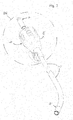
- FIG. 1 shows in side view a medical instrument 1 with a shaft 2, at the proximal end of a handle 3 is arranged. How to continue Fig. 1 can be seen, the shaft 2 is formed in the region of its distal end 4 with respect to the longitudinal axis 5 of the shaft 2 angled. Of course, other designs of the shaft are possible.
- the shaft 2 is mounted rotatably about its longitudinal axis 5 on the handle 3 and fixed relative to the handle 3 via a locking mechanism 6 in different rotational positions.
- the shaft 2 can be fixed releasably to the handle via a coupling mechanism 7 arranged on the shaft 2 on the proximal side, wherein the locking mechanism 6 is arranged at the proximal end of the shaft 2.
- the locking mechanism 6 is formed in the illustrated embodiments as a latching mechanism having at least one perforated disc 9 provided with recesses 9 and locking elements 10, wherein the locking elements 10 and / or the at least one perforated disc 9 are spring-loaded relative to each other and at least one locking element 10 for fixing the Shank 2 engages in a corresponding recess 8 of the at least one perforated disc 9.
- the recesses 8 of the at least one perforated disc 9 are formed to extend in the axial direction of the shaft 2 and the locking elements 10 are arranged axially to the longitudinal axis 5 of the shaft 2.
- This embodiment makes it possible to form the diameter of the medical instrument 1 as low as possible in the region of the locking mechanism 6, which is advantageous in particular when using the medical instrument 1 for endoscopic purposes.
- the locking elements 10 are mounted leading in the illustrated embodiments in locking discs 11.
- the Locking washers 11 ensure a precise alignment of the locking elements 10 relative to the corresponding recesses 8 of the perforated disc. 9
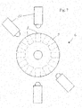
- the recesses 8 of the perforated disc 9 are formed extending in the radial direction of the perforated disc 9 and arranged the locking elements 10 radially star-shaped around the perforated disc 9.
- this design has a larger diameter in the radial direction than the axial alignment of the locking elements 10 in accordance Fig. 3a to Fig. 6b
- this arrangement allows the locking elements 10 a shortened design of the medical instrument 1 in the axial direction.
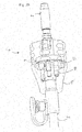
- Fig. 4 and 5 engages in the shaft 2 fixing position in each case a pair of locking elements 10 corresponding recesses 8 of the perforated disc 9 and thus prevents further rotation of the shaft 2 about its longitudinal axis 5. All locking elements 10 are not shown on a spring element in the direction of the perforated disc 9 spring-loaded to ensure a safe locking of the locking elements 10 with the recesses 8 of the perforated disc 9.
- the locking elements 10 are arranged so that not all the locking elements 10 simultaneously receiving in the recesses 8 of the perforated disc 9.
- Fig. 5 it can be seen, takes a two locking elements 10 existing locking element pair 10 an intermediate position. This assumption of the intermediate position is made possible by the spring mounting of the locking elements 10, are pushed back by the locking elements 10, which do not interfere with the perforated disc 9.
- the distance d r of two juxtaposed locking elements 10 from each other which in Fig. 6b is shown
- the distance d a two juxtaposed recesses 8 of the perforated disc 9, which in Fig. 5 is different can be realized for example in two pairs of locking elements, so four individual locking elements, and twelve recesses 8 in the perforated disc 9 a total of twenty-four fixing stages.
- the locking disc 11 or the perforated disc 9 are arranged relative to each other movable away on the shaft 2.
- the release of the lock takes place as in Fig. 4 represented by the fact that the locking disc 11 in the axial direction of the shaft 2 of the perforated disc 9 is movable away.
- the shaft 2 can be easily rotated in the unlocked position to a new position, the locking plate 11, as seen from Fig. 4 seen, at least in the locking mechanism 6 releasing position via a, for example, designed as a ball catch locking device 12 with respect to the axial displaceability is fixed.
- the locking device 12 is designed so that the locking disk 11 is axially fixed both in the locking mechanism 6 releasing and in the locking position.
- the shaft 2 notches 13, in which engages the locking device 12 in the respective position.
- the perforated disc 9 is rotatable about the longitudinal axis 5 of the shaft 2 via a setting device 14, preferably designed as a rotary wheel.
- the adjusting device 14 is preferably designed so that the axial displacement of the locking disk 11 can be carried out via the adjusting device 14.
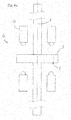
- the in the pictures Fig. 6a and 6b illustrated alternative embodiment for forming the locking mechanism 6 differs from the arrangement according to Fig. 4 and 5 in that in this second embodiment of the locking mechanism 6, the locking elements 10 are mounted in locking discs 11, which are viewed in the axial direction of the shaft 2, in front of and behind the perforated disc 9 are arranged. To increase the number of possible fixation levels, the two locking discs 11, as shown Fig. 6b can be seen, various patterns for the arrangement of the locking elements 10.
- the latching between the locking elements 10 and the recesses 8 of the perforated disc 9 at the in Fig. 6a and 6b embodiment shown also be achieved in that the perforated disc 9 is mounted displaceably in the axial direction on the shaft 2 and can be moved in the direction of the two locking discs 11.
- a medical instrument 1 constructed as described above is distinguished by the fact that the shaft 2 can be rotated more securely and accurately in position into a plurality of fixed positions about its longitudinal axis 5 with simple handling.
Landscapes
- Health & Medical Sciences (AREA)
- Surgery (AREA)
- Life Sciences & Earth Sciences (AREA)
- Biomedical Technology (AREA)
- Nuclear Medicine, Radiotherapy & Molecular Imaging (AREA)
- Engineering & Computer Science (AREA)
- Heart & Thoracic Surgery (AREA)
- Medical Informatics (AREA)
- Molecular Biology (AREA)
- Animal Behavior & Ethology (AREA)
- General Health & Medical Sciences (AREA)
- Public Health (AREA)
- Veterinary Medicine (AREA)
- Ophthalmology & Optometry (AREA)
- Surgical Instruments (AREA)
Abstract
Description
- Die Erfindung betrifft ein medizinisches Instrument mit einem Schaft, an dessen proximalem Ende eine Handhabe angeordnet ist, wobei der Schaft um seine Längsachse gegenüber der Handhabe verdrehbar gelagert ist, beziehungsweise ein distales Schafthauptteil gegenüber einem proximalen Teil des Schaftes, der als ein Verbindungselement wirkt, verdrehbar ist, und über einen Arretiermechanismus in verschiedenen Drehstellungen relativ zur Handhabe festlegbar ist.
- Medizinische Instrumente mit einem um seine Längsachse drehbaren Schaft sind insbesondere bei Instrumenten mit einem zumindest teilweise gebogenen Schaft aus der Praxis bekannt.
- Bei diesen bekannten Instrumenten erfolgt die Fixierung des Schaftes mittels Reibschluss oder Formschluss. Die Formschluss-Fixierungen, bei denen miteinander korrespondierende Formteile ineinandergreifen, weisen in der Regel nur eine geringe Anzahl an Verstellstufen auf.
- Die Reibschluss-Fixierung des Schaftes weist zwar den Vorteil auf, dass das Verdrehen des Schaftes stufenlos erfolgen kann, jedoch weist diese Art der Fixierung auch die Nachteile auf, dass einerseits ein relativ hoher Kraftaufwand erforderlich ist, um die Bauteile fixierend gegeneinander zu verspannen und andererseits die Reibschluss-Fixierung sehr verschleißanfällig ist und darüber hinaus Funktionsprobleme bei Feuchtigkeit aufweisen kann.
- Davon ausgehend liegt der Erfindung die Aufgabe zugrunde, ein medizinisches Instrument mit einem um seine Längsachse drehbaren Schaft so auszugestalten, dass dieses Instrument bei einfacher Handhabung eine Vielzahl sicherer und positionsgenauer Drehungen des Schaftes gegenüber der Handhabe ermöglicht, gleichzeitig jedoch einen möglichst geringen Bauraum einnimmt.
- Die Lösung dieser Aufgabenstellung ist erfindungsgemäß dadurch gekennzeichnet, dass der Arretiermechanismus als Rastmechanismus ausgebildet ist, der mindestens eine mit Ausnehmungen versehene Lochscheibe sowie Rastelemente aufweist, wobei die Rastelemente und/oder die mindestens eine Lochscheibe relativ zueinander federbelastet sind und mindestens ein Rastelement zum Fixieren des Schaftes in eine entsprechende Ausnehmung der mindestens einen Lochscheibe eingreift. Alternativ zu der Lochscheibe kann auch eine Platte mit einer Kontur, z.B. strahlenförmig beziehungsweise radial verlaufenden Ausnehmungen, verwendet werden. Dabei würde wiederum mindestens ein Rastelement zum Fixieren des Schaftes in eine entsprechende Ausnehmung bzw. einen Rücksprung in der Kontur der Lochscheibe eingreifen.
- Die Ausbildung des Arretiermechanismus als Rastmechanismus mit federbelasteten Rastelementen, die in Ausnehmungen einer Lochscheibe eingreifen, stellt eine einfach und sicher zu handhabende Verstell- und Fixiermöglichkeit zum Verdrehen des Schaftes dar, die eine Vielzahl von positionsgenauen Fixierungsstufen ermöglicht.
- Um die Anzahl an Raststufen bei gleicher Lochscheibe zu erhöhen, wird gemäß einer bevorzugten Ausführungsform der Erfindung vorgeschlagen, dass die Rastelemente in Richtung auf die mindestens eine Lochscheibe federbelastet sind und, dass der Abstand zweier nebeneinander angeordneter Rastelemente voneinander sich vom Abstand zweier nebeneinander angeordneter Ausnehmungen der mindestens einen Lochscheibe unterscheidet. Bei der Ausbildung des Abstandes zweier nebeneinanderliegender Rastelemente voneinander auf den halben Abstand zweier nebeneinander angeordneter Ausnehmungen der Lochscheibe verdoppelt sich die Anzahl der mit dieser Lochscheibe zu verwirklichenden Fixierungsstufen. In dieser Ausführungsform rasten immer nur die Hälfte der Rastelemente in die Ausnehmungen ein.
- Gemäß einer praktischen Ausführungsform der Erfindung wird vorgeschlagen, dass in der den Schaft fixierenden Stellung des Arretiermechanismus immer ein aus zwei Rastelementen bestehendes Rastelementepaar in zwei entsprechende Ausnehmungen der mindestens einen Lochscheibe eingreift, um eine stabile und torsionssteife Fixierung zu gewährleisten. Vorteilhafterweise weist der Arretiermechanismus mehrere nebeneinander angeordnete Rastelementepaare auf, um mehrere Fixierungsstufen zu ermöglichen.
- Auch bei der Verrastung mittels der paarweise in die Ausnehmungen der Lochscheibe eingreifenden Rastelementepaare wird mit der Erfindung vorgeschlagen, dass der Abstand zweier nebeneinander angeordneter Rastelementepaare voneinander sich vom Abstand zweier nebeneinander angeordneter Ausnehmungen der mindestens einen Lochscheibe unterscheidet, damit in Abhängigkeit der ungleichen Abstände einerseits der Rastelementepaare voneinander und andererseits der Ausnehmungen der Lochscheibe voneinander lässt sich die Anzahl der möglichen Fixierungsstufen bei gleicher Lochscheibe deutlich erhöhen.
- Um den Durchmesser der medizinischen Instrumente auch im Bereich des Arretiermechanismus möglichst gering ausbilden zu können, wird mit der Erfindung vorgeschlagen, dass die Ausnehmungen der mindestens einen Lochscheibe in Axialrichtung des Schaftes verlaufend ausgebildet sind und die Rastelemente axial zur Längsachse des Schaftes angeordnet sind.
- Zur Anordnung der Rastelemente wird mit einer praktischen Ausführungsform der Erfindung vorgeschlagen, das die Rastelemente in mindestens einer parallel zur mindestens einen Lochscheibe angeordneten Rastscheibe gelagert sind.
- Gemäß einer alternativen Ausführungsform der Erfindung wird weiterhin vorgeschlagen, dass in Axialrichtung des Schaftes betrachtet, vor und hinter der mindestens einen Lochscheibe jeweils eine mit Rastelementen versehene Rastscheibe angeordnet ist.
- Weiterhin wird mit der Erfindung vorgeschlagen, dass die Rastelemente oder die mindestens eine Lochscheibe zum Lösen der Arretiermechanismus relativ zueinander voneinander fort bewegbar sind. Vorteilhafterweise erfolgt das Aufheben der Arretierung erfindungsgemäß dadurch, dass die mindestens eine Rastscheibe in Axialrichtung des Schaftes von der mindestens einen Lochscheibe fort bewegbar ist.
- Um den Schaft in der nicht arretierten Position möglichst einfach in eine neue Position verdrehen zu können, wird gemäß einer vorteilhaften Ausgestaltungsform der Erfindung vorgeschlagen, dass die mindestens eine Rastscheibe zumindest in der die Arretiermechanismus freigebenden Stellung über eine, beispielsweise als Kugelraste ausgebildete Sperrvorrichtung bezüglich der axialen Verschiebbarkeit fixierbar ist.
- Zum manuellen Betätigen des Arretiermechanismus wird mit der Erfindung vorgeschlagen, dass die mindestens eine Lochscheibe über eine Stelleinrichtung um die Längsachse des Schaftes drehbar ist.
- Um die Handhabung des erfindungsgemäßen Arretiermechanismus besonders einfach auszugestalten, wird weiterhin vorgeschlagen, dass auch die mindestens eine Rastscheibe über die Stelleinrichtung in Axialrichtung des Schaftes verschiebbar ist.
- Schließlich wird mit einer alternativen Ausführungsform der Erfindung vorgeschlagen, dass die Ausnehmungen der Lochscheibe in Radialrichtung der Lochscheibe verlaufend ausgebildet sind und die Rastelemente radial sternförmig um die Lochscheibe angeordnet sind. Diese Bauform weist zwar in radialer Richtung einen größeren Durchmesser auf als die axiale Ausrichtung der Rastelemente, jedoch ermöglicht diese Anordnung der Rastelemente eine verkürzte Bauform in axialer Richtung.
- Weiterhin wird mit der Erfindung vorgeschlagen, dass der Schaft über einen Kopplungsmechanismus lösbar an der Handhabe festlegbar ist, wodurch die Möglichkeit besteht, den erfindungsgemäß ausgebildeten Schaft je nach Verwendungszweck an unterschiedlichen Handhaben festzulegen.
- Weitere Merkmale und Vorteile der Erfindung ergeben sich anhand der zugehörigen Zeichnungen, in denen verschiedene Ausführungsbeispiele eines erfindungsgemäßen medizinischen Instruments nur beispielhaft dargestellt sind, ohne die Erfindung auf diese Ausführungsbeispiele zu beschränken. In den Zeichnungen zeigt:
- Fig. 1
- eine Seitenansicht eines erfindungsgemäßen medizinischen Instruments;
- Fig. 2
- eine perspektivische Ansicht des vom medizinischen Instrument gelösten Schaftes;
- Fig. 3a
- eine vergrößerte Darstellung des Details III gemäß
Fig. 2 in einer teilweise transparenten perspektivischen Ansicht in nicht verrasteter Stellung - Fig. 3b
- eine vergrößerte Darstellung des Details III gemäß
Fig. 2 in einer teilweise transparenten perspektivischen Ansicht in verrasteter Stellung - Fig. 4
- eine perspektivische Vorderansicht des Arretiermechanismus gemäß
Fig. 3 ; - Fig. 5
- eine Rückansicht der Darstellung gemäß
Fig. 4 ; - Fig. 6a
- eine schematische Seitenansicht einer alternativen Ausführungsform des Arretiermechanismus;
- Fig. 6b
- eine schematische Vorderansicht der Rastscheiben des Arretiermechanismus gemäß
Fig. 6a und - Fig. 7
- eine schematische Vorderansicht einer weiteren alternativen Ausführungsform des Arretiermechanismus.
- Die Abbildung
Fig. 1 zeigt in der Seitenansicht ein medizinisches Instrument 1 mit einem Schaft 2, an dessen proximalem Ende eine Handhabe 3 angeordnet ist. Wie weiterhin ausFig. 1 ersichtlich, ist der Schaft 2 im Bereich seines distalen Endes 4 gegenüber der Längsachse 5 des Schaftes 2 abgewinkelt ausgebildet. Es sind natürlich auch andere Gestaltungen des Schaftes möglich. - Um das, gemäß dieser Ausführungsform abgewinkelte, distale Ende 4 des Schaftes 2 und somit auch ein in dem hohlen Schaft 2 angeordnetes, nicht dargestelltes, medizinisches Werkzeug positionsgenau positionieren zu können, ist der Schaft 2 um seine Längsachse 5 verdrehbar an der Handhabe 3 gelagert und über einen Arretiermechanismus 6 in verschiedenen Drehstellungen relativ zur Handhabe 3 festlegbar.
- Bei den in den Abbildungen
Fig. 2 bis Fig. 7 dargestellten Ausführungsformen ist der Schaft 2 über einen proximalseitig am Schaft 2 angeordneten Kopplungsmechanismus 7 lösbar an der Handhabe festlegbar, wobei der Arretiermechanismus 6 am proximalen Ende des Schaftes 2 angeordnet ist. - Alternativ ist es selbstverständlich auch möglich, den Arretiermechanismus 6 direkt an der Handhabe 3 anzuordnen.
- Der Arretiermechanismus 6 ist bei den dargestellten Ausführungsformen als Rastmechanismus ausgebildet, der mindestens eine mit Ausnehmungen 8 versehene Lochscheibe 9 sowie Rastelemente 10 aufweist, wobei die Rastelemente 10 und/oder die mindestens eine Lochscheibe 9 relativ zueinander federbelastet sind und mindestens ein Rastelement 10 zum Fixieren des Schaftes 2 in eine entsprechende Ausnehmung 8 der mindestens einen Lochscheibe 9 eingreift.
- Um eine stabile und torsionssteife Fixierung des Schaftes 2 in der den Schaft 2 fixierenden Stellung des Arretiermechanismus 6 zu gewährleisten, greift bei den dargestellten Ausführungsformen immer ein aus zwei Rastelementen 10 bestehendes Rastelementepaar 10 in zwei entsprechende Ausnehmungen 8 der mindestens einen Lochscheibe 9 ein.
- Bei den in den Abbildungen
Fig. 3a bis 6b dargestellten Ausführungsformen sind die Ausnehmungen 8 der mindestens einen Lochscheibe 9 in Axialrichtung des Schaftes 2 verlaufend ausgebildet und die Rastelemente 10 axial zur Längsachse 5 des Schaftes 2 angeordnet. Dieses Ausgestaltungsform ermöglicht es, den Durchmesser des medizinischen Instrumente 1 auch im Bereich des Arretiermechanismus 6 möglichst gering ausbilden zu können, was insbesondere bei der Verwendung des medizinischen Instruments 1 für endoskopische Zwecke vorteilhaft ist. - Wie weiterhin aus den Abbildungen
Fig. 3a bis Fig. 6b ersichtlich, sind die Rastelemente 10 bei den dargestellten Ausführungsformen in Rastscheiben 11 führend gelagert. Die Rastscheiben 11 gewährleisten eine zielgenaue Ausrichtung der Rastelemente 10 relativ zu den korrespondierenden Ausnehmungen 8 der Lochscheibe 9. - Bei der in
Fig. 7 dargestellten alternativen Ausführungsform sind die Ausnehmungen 8 der Lochscheibe 9 in Radialrichtung der Lochscheibe 9 verlaufend ausgebildet und die Rastelemente 10 radial sternförmig um die Lochscheibe 9 angeordnet. Diese Bauform weist zwar in radialer Richtung einen größeren Durchmesser auf als die axiale Ausrichtung der Rastelemente 10 gemäßFig. 3a bis Fig. 6b , jedoch ermöglicht diese Anordnung der Rastelemente 10 eine verkürzte Bauform des medizinischen Instruments 1 in axialer Richtung. - Wie aus
Fig. 4 und5 ersichtlich, greift in der den Schaft 2 fixierenden Stellung jeweils ein Rastelementepaar 10 entsprechende Ausnehmungen 8 der Lochscheibe 9 ein und verhindert so ein weiteres Verdrehen des Schaftes 2 um dessen Längsachse 5. Alle Rastelemente 10 sind dabei über ein nicht dargestelltes Federelement in Richtung auf die Lochscheibe 9 federbelastet, um ein sicheres Verrasten der Rastelemente 10 mit den Ausnehmungen 8 der Lochscheibe 9 zu gewährleisten. - Um möglichst viele positionsgenaue Fixierstufen mit ein und derselben Lochscheibe 9 verwirklichen zu können, sind die Rastelemente 10 so angeordnet, dass nicht alle Rastelemente 10 gleichzeitig Aufnahme in den Ausnehmungen 8 der Lochscheibe 9 finden. Wie insbesondere aus
Fig. 5 ersichtlich, nimmt ein aus zwei Rastelementen 10 bestehendes Rastelementepaar 10 eine Zwischenposition ein. Diese Einnahme der Zwischenposition wird durch die Federlagerung der Rastelemente 10 ermöglicht, durch die Rastelemente 10, die nicht mit der Lochscheibe 9 in Eingriff treten, zurückgeschoben werden. - Dadurch, dass sich der Abstand dr zweier nebeneinander angeordneter Rastelemente 10 voneinander, was in
Fig. 6b abgebildet ist, vom Abstand da zweier nebeneinander angeordneter Ausnehmungen 8 der Lochscheibe 9, was inFig. 5 abgebildet ist, unterscheidet, lassen sich beispielsweise bei zwei Rastelementepaaren, also vier einzelnen Rastelementen, und zwölf Ausnehmungen 8 in der Lochscheibe 9 insgesamt vierundzwanzig Fixierungsstufen verwirklichen. - Zum Lösen des Arretiermechanismus 6 sind die Rastscheibe 11 oder die Lochscheibe 9 relativ zueinander voneinander fort bewegbar auf dem Schaft 2 angeordnet. Vorteilhafter-weise erfolgt das Aufheben der Arretierung wie in
Fig. 4 dargestellt dadurch, dass die Rastscheibe 11 in Axialrichtung des Schaftes 2 von der Lochscheibe 9 fort bewegbar ist. - Damit der Schaft 2 in der nicht arretierten Position möglichst einfach in eine neue Position verdreht werden kann, ist die Rastscheibe 11, wie aus
Fig. 4 ersichtlich, zumindest in der die Arretiermechanismus 6 freigebenden Stellung über eine, beispielsweise als Kugelraste ausgebildete Sperrvorrichtung 12 bezüglich der axialen Verschiebbarkeit fixierbar ist. Vorteilhafterweise ist die Sperreinrichtung 12 aber so ausgebildet, dass die Rastscheibe 11 sowohl in der den Arretiermechanismus 6 freigebenden als auch in der arretierenden Position axial fixierbar ist. Hierzu weist der Schaft 2 Kerben 13 auf, in die die Sperreinrichtung 12 in der jeweiligen Position eingreift. - Zum manuellen Betätigen des Arretiermechanismus 6 gemäß
Fig. 4 und5 ist die Lochscheibe 9 über eine, vorzugsweise als Drehrad ausgebildete Stelleinrichtung 14 um die Längsachse 5 des Schaftes 2 drehbar. - Um die Handhabung des Arretiermechanismus 6 besonders einfach auszugestalten, ist die Stelleinrichtung 14 vorzugsweise so ausgebildet, dass auch das axiale Verschieben der Rastscheibe 11 über die Stelleinrichtung 14 erfolgen kann.
- Die in den Abbildungen
Fig. 6a und6b dargestellte alternative Ausführungsform zur Ausbildung des Arretiermechanimus 6 unterscheidet sich von der Anordnung gemäßFig. 4 und5 dadurch, dass bei dieser zweiten Ausführungsform des Arretiermechanismus 6 die Rastelemente 10 in Rastscheiben 11 gelagert sind, die in Axialrichtung des Schaftes 2 betrachtet, vor und hinter der Lochscheibe 9 angeordnet sind. Um die Anzahl der möglichen Fixierungsstufen zu erhöhen, weisen die beiden Rastscheiben 11, wie ausFig. 6b ersichtlich, verschiedene Muster zur Anordnung der Rastelemente 10 auf. - Alternativ zu der Federbelastung der Rastelemente 10 kann die Verrastung zwischen den Rastelementen 10 und den Ausnehmungen 8 der Lochscheibe 9 bei der in
Fig. 6a und6b dargestellten Ausführungsform auch dadurch erreicht werden, dass die Lochscheibe 9 in Axialrichtung verschiebbar auf dem Schaft 2 gelagert ist und so in Richtung der beiden Rastscheiben 11 verschoben werden kann. - Ein wie voranstehend beschrieben aufgebautes medizinisches Instrument 1 zeichnet sich dadurch aus, dass der Schaft 2 bei einfacher Handhabung sicherer und positionsgenau in eine Vielzahl fester Positionen um seine Längsachse 5 verdreht werden kann.
-
- 1
- medizinisches Instrument
- 2
- Schaft
- 3
- Handhabe
- 4
- distales Ende (Schaft)
- 5
- Längsachse
- 6
- Arretiermechanismus
- 7
- Kopplungsmechanismus
- 8
- Ausnehmung
- 9
- Lochscheibe
- 10
- Rastelement / Rastelementepaar
- 11
- Rastscheibe
- 12
- Sperreinrichtung
- 13
- Kerbe
- 14
- Stelleinrichtung
- dr
- Abstand (Rastelemente)
- da
- Abstand (Ausnehmungen)
Claims (16)
- Medizinisches Instrument mit einem Schaft (2), an dessen proximalem Ende eine Handhabe (3) angeordnet ist, wobei der Schaft (2) um seine Längsachse (5) verdrehbar gegenüber der Handhabe (2) gelagert ist und über einen Arretiermechanismus (6) in verschiedenen Drehstellungen relativ zur Handhabe (3) festlegbar ist,
dadurch gekennzeichnet,
dass der Arretiermechanismus (6) als Rastmechanismus ausgebildet ist, der mindestens eine mit Ausnehmungen (8) versehene Lochscheibe (9) sowie Rastelemente (10) aufweist, wobei die Rastelemente (10) und/oder die mindestens eine Lochscheibe (9) relativ zueinander federbelastet sind und mindestens ein Rastelement (10) zum Fixieren des Schaftes (2) in eine entsprechende Ausnehmung (8) der mindestens einen Lochscheibe (9) eingreift. - Medizinisches Instrument nach Anspruch 1, dadurch gekennzeichnet, dass die Rastelemente (10) in Richtung auf die mindestens eine Lochscheibe (9) federbelastet sind und, dass der Abstand (dr) zweier nebeneinander angeordneter Rastelemente (10) voneinander sich vom Abstand (da) zweier nebeneinander angeordneter Ausnehmungen (8) der mindestens einen Lochscheibe (9) unterscheidet.
- Medizinisches Instrument nach Anspruch 2, dadurch gekennzeichnet, dass in der den Schaft (2) fixierenden Stellung des Arretiermechanismus (6) immer ein aus zwei Rastelementen (10) bestehendes Rastelementepaar (10) in zwei entsprechende Ausnehmungen (8) der mindestens einen Lochscheibe (9) eingreift.
- Medizinisches Instrument nach Anspruch 3, dadurch gekennzeichnet, dass der Arretiermechanismus (6) mehrere nebeneinander angeordnete Rastelementepaare (10) aufweist.
- Medizinisches Instrument nach Anspruch 4, dadurch gekennzeichnet, dass der Abstand (dr) zweier nebeneinander angeordneter Rastelementepaare (10) voneinander sich vom Abstand (da) zweier nebeneinander angeordneter Ausnehmungen (8) der mindestens einen Lochscheibe (9) unterscheidet.
- Medizinisches Instrument nach einem der Ansprüche 1 bis 5, dadurch gekennzeichnet, dass die Ausnehmungen (8) der mindestens einen Lochscheibe (9) in Axialrichtung des Schaftes (2) verlaufend ausgebildet sind und die Rastelemente (10) axial zur Längsachse (5) des Schaftes (2) angeordnet sind.
- Medizinisches Instrument nach Anspruch 6, dadurch gekennzeichnet, dass die Rastelemente (10) in mindestens einer parallel zur mindestens einen Lochscheibe (9) angeordneten Rastscheibe (11) gelagert sind.
- Medizinisches Instrument nach Anspruch 7, dadurch gekennzeichnet, dass in Axialrichtung des Schaftes (2) betrachtet, vor und hinter der mindestens einen Lochscheibe (9) jeweils eine mit Rastelementen (10) versehene Rastscheibe (11) angeordnet ist.
- Medizinisches Instrument nach einem der Ansprüche 1 bis 8, dadurch gekennzeichnet, dass die Rastelemente (10) oder die mindestens eine Lochscheibe (9) zum Lösen des Arretiermechanismus (6) relativ zueinander voneinander fort bewegbar sind.
- Medizinisches Instrument nach den Ansprüchen 7 und 9, dadurch gekennzeichnet, dass die mindestens eine Rastscheibe (11) in Axialrichtung des Schaftes (2) von der mindestens einen Lochscheibe (9) fort bewegbar ist.
- Medizinisches Instrument nach Anspruch 10, dadurch gekennzeichnet, dass die mindestens eine Rastscheibe (11) zumindest in der die Arretiermechanismus (6) freigebenden Stellung über eine Sperrvorrichtung (12) bezüglich der axialen Verschiebbarkeit fixierbar ist.
- Medizinisches Instrument nach Anspruch 11, dadurch gekennzeichnet, dass die Sperrvorrichtung (12) als Kugelraste ausgebildet ist.
- Medizinisches Instrument nach einem der Ansprüche 1 bis 12, dadurch gekennzeichnet, dass die mindestens eine Lochscheibe (9) über eine Stelleinrichtung (14) um die Längsachse (5) des Schaftes (2) drehbar ist.
- Medizinisches Instrument nach Anspruch 13, dadurch gekennzeichnet, dass die mindestens eine Rastscheibe (11) über die Stelleinrichtung (14) in Axialrichtung des Schaftes (2) verschiebbar ist.
- Medizinisches Instrument nach einem der Ansprüche 1 bis 4, dadurch gekennzeichnet, dass die Ausnehmungen (8) der Lochscheibe (9) in Radialrichtung der Lochscheibe (9) verlaufend ausgebildet sind und die Rastelemente (10) radial sternförmig um die Lochscheibe (9) angeordnet sind.
- Medizinisches Instrument nach einem der Ansprüche 1 bis 4, dadurch gekennzeichnet, dass der Schaft (2) über einen Kopplungsmechanismus (7) lösbar an der Handhabe (3) festlegbar ist.
Applications Claiming Priority (1)
| Application Number | Priority Date | Filing Date | Title |
|---|---|---|---|
| DE102013100759.7A DE102013100759A1 (de) | 2013-01-25 | 2013-01-25 | Medizinisches Instrument |
Publications (2)
| Publication Number | Publication Date |
|---|---|
| EP2759270A1 true EP2759270A1 (de) | 2014-07-30 |
| EP2759270B1 EP2759270B1 (de) | 2018-08-29 |
Family
ID=50072872
Family Applications (1)
| Application Number | Title | Priority Date | Filing Date |
|---|---|---|---|
| EP14152440.5A Active EP2759270B1 (de) | 2013-01-25 | 2014-01-24 | Medizinisches Instrument |
Country Status (3)
| Country | Link |
|---|---|
| US (1) | US9445792B2 (de) |
| EP (1) | EP2759270B1 (de) |
| DE (1) | DE102013100759A1 (de) |
Cited By (1)
| Publication number | Priority date | Publication date | Assignee | Title |
|---|---|---|---|---|
| EP4321107A1 (de) * | 2022-08-09 | 2024-02-14 | Aesculap AG | Medizinisches motorhandstück mit rast- und/oder anschlageinheit |
Citations (5)
| Publication number | Priority date | Publication date | Assignee | Title |
|---|---|---|---|---|
| US5176702A (en) * | 1991-04-04 | 1993-01-05 | Symbiosis Corporation | Ratchet locking mechanism for surgical instruments |
| EP2316358A1 (de) * | 2009-10-31 | 2011-05-04 | Richard Wolf GmbH | Medizinisches Instrument |
| US20110166575A1 (en) * | 2010-01-04 | 2011-07-07 | Zyga Technology, Inc. | Sacroiliac fusion system |
| DE102010024136A1 (de) * | 2010-06-17 | 2011-12-22 | Olympus Winter & Ibe Gmbh | Uterusmanipulator mit verstellbarer Portiokappe |
| EP2489315A1 (de) * | 2011-02-15 | 2012-08-22 | Karl Storz GmbH & Co. KG | Medizinisches Instrument |
Family Cites Families (18)
| Publication number | Priority date | Publication date | Assignee | Title |
|---|---|---|---|---|
| US745722A (en) * | 1902-10-09 | 1903-12-01 | Chester M Freeman | Dental tool. |
| US4471781A (en) * | 1982-02-03 | 1984-09-18 | Ethicon, Inc. | Surgical instrument with rotatable front housing and latch mechanism |
| US5376078B1 (en) * | 1992-12-10 | 1997-06-24 | Linvatec Corp | Rotatable surgical cutting instrument with positionally adjustable window |
| GB9805372D0 (en) * | 1998-03-14 | 1998-05-06 | Renishaw Plc | Indexing mechanism |
| US7955323B2 (en) * | 2000-06-24 | 2011-06-07 | Greatbatch Medical S.A. | Instrument holder and method for a surgical instrument having a park position |
| US20040147909A1 (en) * | 2002-12-20 | 2004-07-29 | Gyrus Ent L.L.C. | Surgical instrument |
| US7909873B2 (en) * | 2006-12-15 | 2011-03-22 | Soteira, Inc. | Delivery apparatus and methods for vertebrostenting |
| US7828808B2 (en) * | 2004-06-07 | 2010-11-09 | Novare Surgical Systems, Inc. | Link systems and articulation mechanisms for remote manipulation of surgical or diagnostic tools |
| US7947034B2 (en) * | 2004-07-30 | 2011-05-24 | Tyco Healthcare Group Lp | Flexible shaft extender and method of using same |
| DE102004054866B3 (de) * | 2004-11-12 | 2006-08-03 | Deutsches Zentrum für Luft- und Raumfahrt e.V. | Vorrichtung zum Anschließen von konventionellen oder laparoskopischen Instrumenten an einen Roboter |
| US20060287643A1 (en) * | 2005-06-16 | 2006-12-21 | Marsh Surgical, Inc. | Surgical instrument with detachable sleeve assembly |
| US20060287642A1 (en) * | 2005-06-16 | 2006-12-21 | Alfred Perlin | Laparoscopic surgical instrument having lockable handles with a latch feature |
| JP5043842B2 (ja) * | 2005-07-27 | 2012-10-10 | タイコ ヘルスケア グループ リミテッド パートナーシップ | 電気機械的手術装置用のシャフト |
| US7568603B2 (en) * | 2006-01-31 | 2009-08-04 | Ethicon Endo-Surgery, Inc. | Motor-driven surgical cutting and fastening instrument with articulatable end effector |
| DE102006010316A1 (de) * | 2006-03-07 | 2007-09-13 | Karl Storz Gmbh & Co. Kg | Kupplungsmechanismus |
| US8992422B2 (en) * | 2006-03-23 | 2015-03-31 | Ethicon Endo-Surgery, Inc. | Robotically-controlled endoscopic accessory channel |
| DE102007021658A1 (de) * | 2007-05-04 | 2008-11-06 | Karl Storz Gmbh & Co. Kg | Zerlegbares medizinisches Zangensystem |
| US7886637B2 (en) * | 2009-01-30 | 2011-02-15 | Black & Decker Inc. | Multiple pin retention for universal socket |
-
2013
- 2013-01-25 DE DE102013100759.7A patent/DE102013100759A1/de not_active Withdrawn
-
2014
- 2014-01-24 EP EP14152440.5A patent/EP2759270B1/de active Active
- 2014-01-24 US US14/163,769 patent/US9445792B2/en active Active
Patent Citations (5)
| Publication number | Priority date | Publication date | Assignee | Title |
|---|---|---|---|---|
| US5176702A (en) * | 1991-04-04 | 1993-01-05 | Symbiosis Corporation | Ratchet locking mechanism for surgical instruments |
| EP2316358A1 (de) * | 2009-10-31 | 2011-05-04 | Richard Wolf GmbH | Medizinisches Instrument |
| US20110166575A1 (en) * | 2010-01-04 | 2011-07-07 | Zyga Technology, Inc. | Sacroiliac fusion system |
| DE102010024136A1 (de) * | 2010-06-17 | 2011-12-22 | Olympus Winter & Ibe Gmbh | Uterusmanipulator mit verstellbarer Portiokappe |
| EP2489315A1 (de) * | 2011-02-15 | 2012-08-22 | Karl Storz GmbH & Co. KG | Medizinisches Instrument |
Cited By (2)
| Publication number | Priority date | Publication date | Assignee | Title |
|---|---|---|---|---|
| EP4321107A1 (de) * | 2022-08-09 | 2024-02-14 | Aesculap AG | Medizinisches motorhandstück mit rast- und/oder anschlageinheit |
| DE102022119980A1 (de) * | 2022-08-09 | 2024-02-15 | Aesculap Ag | Medizinisches Motorhandstück mit Rast- und/oder Anschlageinheit |
Also Published As
| Publication number | Publication date |
|---|---|
| US9445792B2 (en) | 2016-09-20 |
| EP2759270B1 (de) | 2018-08-29 |
| DE102013100759A1 (de) | 2014-07-31 |
| US20140214011A1 (en) | 2014-07-31 |
Similar Documents
| Publication | Publication Date | Title |
|---|---|---|
| DE112013002802B4 (de) | Gewichtsgerät mit Gewichtseinstellungseinrichtung | |
| DE102011011244A1 (de) | Medizinisches Instrument | |
| EP2759270B1 (de) | Medizinisches Instrument | |
| DE4425705C2 (de) | Endoskopisches Instrument | |
| DE1447380B2 (de) | Schaltvorrichtung zur kinematischen verbindung einer sich stetig drehenden antriebswelle mit einer abtriebswelle | |
| DE1165988B (de) | Pankratisches Objektiv | |
| DE19815198A1 (de) | Kombiniertes Normal- und Feinsärad | |
| EP0541921B1 (de) | Dosiervorrichtung für eine Sämaschine | |
| DE102014209165A1 (de) | Schaltvorrichtung sowie Kraftfahrzeug | |
| EP0428029B1 (de) | Schliesseinrichtung | |
| DE112013006363B4 (de) | Endoskop | |
| DE102017129057A1 (de) | Winkelverstellbares Scharnier | |
| DE102020122235A1 (de) | Ausrichtvorrichtung zum Ausrichten und Positionieren mindestens eines Drahts | |
| EP4125765B1 (de) | Fussrotationsvorrichtung | |
| DE102014213134B4 (de) | Scheibenanordnung mit einstellbarer axialer Dicke sowie Schaltanordnung mit der Scheibenanordnung | |
| DE102010034261A1 (de) | Vorrichtung zum Erfassen eines Positionswinkels eines drehbaren Bauteils eines Fahrzeugs sowie Fahrzeug mit einer derartigen Vorrichtung | |
| DE1428524A1 (de) | Doppelzylinderschloss | |
| DE457588C (de) | Gelenkbolzensicherung | |
| DE553775C (de) | Malschloss | |
| DE369752C (de) | Schloss mit Zahnstangenriegel | |
| DE1243763B (de) | Doppelter Stufendrehschalter | |
| DE3937611A1 (de) | Schliesseinrichtung | |
| DE202011052144U1 (de) | Schwenkgelenk | |
| DE659741C (de) | Elastische Verbindung mit verstellbarer Winkellage, insbesondere fuer Zuendmagnete | |
| DE1447380C (de) | Schaltvorrichtung zur kinematischen Verbindung einer sich stetig drehen den Antriebswelle mit einer Abtriebs welle |
Legal Events
| Date | Code | Title | Description |
|---|---|---|---|
| PUAI | Public reference made under article 153(3) epc to a published international application that has entered the european phase |
Free format text: ORIGINAL CODE: 0009012 |
|
| 17P | Request for examination filed |
Effective date: 20140124 |
|
| AK | Designated contracting states |
Kind code of ref document: A1 Designated state(s): AL AT BE BG CH CY CZ DE DK EE ES FI FR GB GR HR HU IE IS IT LI LT LU LV MC MK MT NL NO PL PT RO RS SE SI SK SM TR |
|
| R17P | Request for examination filed (corrected) |
Effective date: 20150108 |
|
| RBV | Designated contracting states (corrected) |
Designated state(s): AL AT BE BG CH CY CZ DE DK EE ES FI FR GB GR HR HU IE IS IT LI LT LU LV MC MK MT NL NO PL PT RO RS SE SI SK SM TR |
|
| RAP1 | Party data changed (applicant data changed or rights of an application transferred) |
Owner name: KARL STORZ SE & CO. KG |
|
| RIC1 | Information provided on ipc code assigned before grant |
Ipc: A61B 17/00 20060101ALN20180419BHEP Ipc: A61B 17/29 20060101AFI20180419BHEP |
|
| GRAP | Despatch of communication of intention to grant a patent |
Free format text: ORIGINAL CODE: EPIDOSNIGR1 |
|
| STAA | Information on the status of an ep patent application or granted ep patent |
Free format text: STATUS: GRANT OF PATENT IS INTENDED |
|
| INTG | Intention to grant announced |
Effective date: 20180607 |
|
| RIC1 | Information provided on ipc code assigned before grant |
Ipc: A61B 17/29 20060101AFI20180529BHEP Ipc: A61B 17/00 20060101ALN20180529BHEP |
|
| RIN1 | Information on inventor provided before grant (corrected) |
Inventor name: MERZ, ROBIN Inventor name: KAERCHER, DANIEL |
|
| GRAS | Grant fee paid |
Free format text: ORIGINAL CODE: EPIDOSNIGR3 |
|
| GRAA | (expected) grant |
Free format text: ORIGINAL CODE: 0009210 |
|
| STAA | Information on the status of an ep patent application or granted ep patent |
Free format text: STATUS: THE PATENT HAS BEEN GRANTED |
|
| AK | Designated contracting states |
Kind code of ref document: B1 Designated state(s): AL AT BE BG CH CY CZ DE DK EE ES FI FR GB GR HR HU IE IS IT LI LT LU LV MC MK MT NL NO PL PT RO RS SE SI SK SM TR |
|
| REG | Reference to a national code |
Ref country code: GB Ref legal event code: FG4D Free format text: NOT ENGLISH |
|
| REG | Reference to a national code |
Ref country code: CH Ref legal event code: EP |
|
| REG | Reference to a national code |
Ref country code: AT Ref legal event code: REF Ref document number: 1034210 Country of ref document: AT Kind code of ref document: T Effective date: 20180915 |
|
| REG | Reference to a national code |
Ref country code: IE Ref legal event code: FG4D Free format text: LANGUAGE OF EP DOCUMENT: GERMAN |
|
| REG | Reference to a national code |
Ref country code: DE Ref legal event code: R096 Ref document number: 502014009287 Country of ref document: DE |
|
| REG | Reference to a national code |
Ref country code: NL Ref legal event code: MP Effective date: 20180829 |
|
| REG | Reference to a national code |
Ref country code: LT Ref legal event code: MG4D |
|
| PG25 | Lapsed in a contracting state [announced via postgrant information from national office to epo] |
Ref country code: LT Free format text: LAPSE BECAUSE OF FAILURE TO SUBMIT A TRANSLATION OF THE DESCRIPTION OR TO PAY THE FEE WITHIN THE PRESCRIBED TIME-LIMIT Effective date: 20180829 Ref country code: GR Free format text: LAPSE BECAUSE OF FAILURE TO SUBMIT A TRANSLATION OF THE DESCRIPTION OR TO PAY THE FEE WITHIN THE PRESCRIBED TIME-LIMIT Effective date: 20181130 Ref country code: BG Free format text: LAPSE BECAUSE OF FAILURE TO SUBMIT A TRANSLATION OF THE DESCRIPTION OR TO PAY THE FEE WITHIN THE PRESCRIBED TIME-LIMIT Effective date: 20181129 Ref country code: NL Free format text: LAPSE BECAUSE OF FAILURE TO SUBMIT A TRANSLATION OF THE DESCRIPTION OR TO PAY THE FEE WITHIN THE PRESCRIBED TIME-LIMIT Effective date: 20180829 Ref country code: NO Free format text: LAPSE BECAUSE OF FAILURE TO SUBMIT A TRANSLATION OF THE DESCRIPTION OR TO PAY THE FEE WITHIN THE PRESCRIBED TIME-LIMIT Effective date: 20181129 Ref country code: IS Free format text: LAPSE BECAUSE OF FAILURE TO SUBMIT A TRANSLATION OF THE DESCRIPTION OR TO PAY THE FEE WITHIN THE PRESCRIBED TIME-LIMIT Effective date: 20181229 Ref country code: RS Free format text: LAPSE BECAUSE OF FAILURE TO SUBMIT A TRANSLATION OF THE DESCRIPTION OR TO PAY THE FEE WITHIN THE PRESCRIBED TIME-LIMIT Effective date: 20180829 Ref country code: FI Free format text: LAPSE BECAUSE OF FAILURE TO SUBMIT A TRANSLATION OF THE DESCRIPTION OR TO PAY THE FEE WITHIN THE PRESCRIBED TIME-LIMIT Effective date: 20180829 Ref country code: SE Free format text: LAPSE BECAUSE OF FAILURE TO SUBMIT A TRANSLATION OF THE DESCRIPTION OR TO PAY THE FEE WITHIN THE PRESCRIBED TIME-LIMIT Effective date: 20180829 |
|
| PG25 | Lapsed in a contracting state [announced via postgrant information from national office to epo] |
Ref country code: LV Free format text: LAPSE BECAUSE OF FAILURE TO SUBMIT A TRANSLATION OF THE DESCRIPTION OR TO PAY THE FEE WITHIN THE PRESCRIBED TIME-LIMIT Effective date: 20180829 Ref country code: AL Free format text: LAPSE BECAUSE OF FAILURE TO SUBMIT A TRANSLATION OF THE DESCRIPTION OR TO PAY THE FEE WITHIN THE PRESCRIBED TIME-LIMIT Effective date: 20180829 Ref country code: HR Free format text: LAPSE BECAUSE OF FAILURE TO SUBMIT A TRANSLATION OF THE DESCRIPTION OR TO PAY THE FEE WITHIN THE PRESCRIBED TIME-LIMIT Effective date: 20180829 |
|
| PG25 | Lapsed in a contracting state [announced via postgrant information from national office to epo] |
Ref country code: EE Free format text: LAPSE BECAUSE OF FAILURE TO SUBMIT A TRANSLATION OF THE DESCRIPTION OR TO PAY THE FEE WITHIN THE PRESCRIBED TIME-LIMIT Effective date: 20180829 Ref country code: PL Free format text: LAPSE BECAUSE OF FAILURE TO SUBMIT A TRANSLATION OF THE DESCRIPTION OR TO PAY THE FEE WITHIN THE PRESCRIBED TIME-LIMIT Effective date: 20180829 Ref country code: CZ Free format text: LAPSE BECAUSE OF FAILURE TO SUBMIT A TRANSLATION OF THE DESCRIPTION OR TO PAY THE FEE WITHIN THE PRESCRIBED TIME-LIMIT Effective date: 20180829 Ref country code: RO Free format text: LAPSE BECAUSE OF FAILURE TO SUBMIT A TRANSLATION OF THE DESCRIPTION OR TO PAY THE FEE WITHIN THE PRESCRIBED TIME-LIMIT Effective date: 20180829 Ref country code: ES Free format text: LAPSE BECAUSE OF FAILURE TO SUBMIT A TRANSLATION OF THE DESCRIPTION OR TO PAY THE FEE WITHIN THE PRESCRIBED TIME-LIMIT Effective date: 20180829 |
|
| PG25 | Lapsed in a contracting state [announced via postgrant information from national office to epo] |
Ref country code: DK Free format text: LAPSE BECAUSE OF FAILURE TO SUBMIT A TRANSLATION OF THE DESCRIPTION OR TO PAY THE FEE WITHIN THE PRESCRIBED TIME-LIMIT Effective date: 20180829 Ref country code: SM Free format text: LAPSE BECAUSE OF FAILURE TO SUBMIT A TRANSLATION OF THE DESCRIPTION OR TO PAY THE FEE WITHIN THE PRESCRIBED TIME-LIMIT Effective date: 20180829 Ref country code: SK Free format text: LAPSE BECAUSE OF FAILURE TO SUBMIT A TRANSLATION OF THE DESCRIPTION OR TO PAY THE FEE WITHIN THE PRESCRIBED TIME-LIMIT Effective date: 20180829 |
|
| REG | Reference to a national code |
Ref country code: DE Ref legal event code: R097 Ref document number: 502014009287 Country of ref document: DE |
|
| PLBE | No opposition filed within time limit |
Free format text: ORIGINAL CODE: 0009261 |
|
| STAA | Information on the status of an ep patent application or granted ep patent |
Free format text: STATUS: NO OPPOSITION FILED WITHIN TIME LIMIT |
|
| 26N | No opposition filed |
Effective date: 20190531 |
|
| PG25 | Lapsed in a contracting state [announced via postgrant information from national office to epo] |
Ref country code: MC Free format text: LAPSE BECAUSE OF FAILURE TO SUBMIT A TRANSLATION OF THE DESCRIPTION OR TO PAY THE FEE WITHIN THE PRESCRIBED TIME-LIMIT Effective date: 20180829 Ref country code: SI Free format text: LAPSE BECAUSE OF FAILURE TO SUBMIT A TRANSLATION OF THE DESCRIPTION OR TO PAY THE FEE WITHIN THE PRESCRIBED TIME-LIMIT Effective date: 20180829 |
|
| REG | Reference to a national code |
Ref country code: CH Ref legal event code: PL |
|
| PG25 | Lapsed in a contracting state [announced via postgrant information from national office to epo] |
Ref country code: LU Free format text: LAPSE BECAUSE OF NON-PAYMENT OF DUE FEES Effective date: 20190124 |
|
| REG | Reference to a national code |
Ref country code: BE Ref legal event code: MM Effective date: 20190131 |
|
| REG | Reference to a national code |
Ref country code: IE Ref legal event code: MM4A |
|
| PG25 | Lapsed in a contracting state [announced via postgrant information from national office to epo] |
Ref country code: BE Free format text: LAPSE BECAUSE OF NON-PAYMENT OF DUE FEES Effective date: 20190131 |
|
| PG25 | Lapsed in a contracting state [announced via postgrant information from national office to epo] |
Ref country code: CH Free format text: LAPSE BECAUSE OF NON-PAYMENT OF DUE FEES Effective date: 20190131 Ref country code: LI Free format text: LAPSE BECAUSE OF NON-PAYMENT OF DUE FEES Effective date: 20190131 |
|
| PG25 | Lapsed in a contracting state [announced via postgrant information from national office to epo] |
Ref country code: IE Free format text: LAPSE BECAUSE OF NON-PAYMENT OF DUE FEES Effective date: 20190124 |
|
| REG | Reference to a national code |
Ref country code: AT Ref legal event code: MM01 Ref document number: 1034210 Country of ref document: AT Kind code of ref document: T Effective date: 20190124 |
|
| PG25 | Lapsed in a contracting state [announced via postgrant information from national office to epo] |
Ref country code: TR Free format text: LAPSE BECAUSE OF FAILURE TO SUBMIT A TRANSLATION OF THE DESCRIPTION OR TO PAY THE FEE WITHIN THE PRESCRIBED TIME-LIMIT Effective date: 20180829 |
|
| PG25 | Lapsed in a contracting state [announced via postgrant information from national office to epo] |
Ref country code: AT Free format text: LAPSE BECAUSE OF NON-PAYMENT OF DUE FEES Effective date: 20190124 |
|
| PG25 | Lapsed in a contracting state [announced via postgrant information from national office to epo] |
Ref country code: MT Free format text: LAPSE BECAUSE OF FAILURE TO SUBMIT A TRANSLATION OF THE DESCRIPTION OR TO PAY THE FEE WITHIN THE PRESCRIBED TIME-LIMIT Effective date: 20180829 Ref country code: PT Free format text: LAPSE BECAUSE OF FAILURE TO SUBMIT A TRANSLATION OF THE DESCRIPTION OR TO PAY THE FEE WITHIN THE PRESCRIBED TIME-LIMIT Effective date: 20181229 |
|
| PG25 | Lapsed in a contracting state [announced via postgrant information from national office to epo] |
Ref country code: CY Free format text: LAPSE BECAUSE OF FAILURE TO SUBMIT A TRANSLATION OF THE DESCRIPTION OR TO PAY THE FEE WITHIN THE PRESCRIBED TIME-LIMIT Effective date: 20180829 |
|
| PG25 | Lapsed in a contracting state [announced via postgrant information from national office to epo] |
Ref country code: HU Free format text: LAPSE BECAUSE OF FAILURE TO SUBMIT A TRANSLATION OF THE DESCRIPTION OR TO PAY THE FEE WITHIN THE PRESCRIBED TIME-LIMIT; INVALID AB INITIO Effective date: 20140124 |
|
| PG25 | Lapsed in a contracting state [announced via postgrant information from national office to epo] |
Ref country code: MK Free format text: LAPSE BECAUSE OF FAILURE TO SUBMIT A TRANSLATION OF THE DESCRIPTION OR TO PAY THE FEE WITHIN THE PRESCRIBED TIME-LIMIT Effective date: 20180829 |
|
| P01 | Opt-out of the competence of the unified patent court (upc) registered |
Effective date: 20230528 |
|
| PGFP | Annual fee paid to national office [announced via postgrant information from national office to epo] |
Ref country code: GB Payment date: 20260126 Year of fee payment: 13 |
|
| PGFP | Annual fee paid to national office [announced via postgrant information from national office to epo] |
Ref country code: DE Payment date: 20260127 Year of fee payment: 13 |
|
| PGFP | Annual fee paid to national office [announced via postgrant information from national office to epo] |
Ref country code: IT Payment date: 20260123 Year of fee payment: 13 |
|
| PGFP | Annual fee paid to national office [announced via postgrant information from national office to epo] |
Ref country code: FR Payment date: 20260126 Year of fee payment: 13 |