EP2757079A1 - Hausgerätevorrichtung - Google Patents
Hausgerätevorrichtung Download PDFInfo
- Publication number
- EP2757079A1 EP2757079A1 EP13382020.9A EP13382020A EP2757079A1 EP 2757079 A1 EP2757079 A1 EP 2757079A1 EP 13382020 A EP13382020 A EP 13382020A EP 2757079 A1 EP2757079 A1 EP 2757079A1
- Authority
- EP
- European Patent Office
- Prior art keywords
- coating
- structuring
- plate unit
- domestic appliance
- appliance device
- Prior art date
- Legal status (The legal status is an assumption and is not a legal conclusion. Google has not performed a legal analysis and makes no representation as to the accuracy of the status listed.)
- Granted
Links
Images
Classifications
-
- C—CHEMISTRY; METALLURGY
- C03—GLASS; MINERAL OR SLAG WOOL
- C03C—CHEMICAL COMPOSITION OF GLASSES, GLAZES OR VITREOUS ENAMELS; SURFACE TREATMENT OF GLASS; SURFACE TREATMENT OF FIBRES OR FILAMENTS MADE FROM GLASS, MINERALS OR SLAGS; JOINING GLASS TO GLASS OR OTHER MATERIALS
- C03C23/00—Other surface treatment of glass not in the form of fibres or filaments
- C03C23/0005—Other surface treatment of glass not in the form of fibres or filaments by irradiation
- C03C23/0025—Other surface treatment of glass not in the form of fibres or filaments by irradiation by a laser beam
-
- F—MECHANICAL ENGINEERING; LIGHTING; HEATING; WEAPONS; BLASTING
- F24—HEATING; RANGES; VENTILATING
- F24C—DOMESTIC STOVES OR RANGES ; DETAILS OF DOMESTIC STOVES OR RANGES, OF GENERAL APPLICATION
- F24C15/00—Details
- F24C15/10—Tops, e.g. hot plates; Rings
Definitions
- the invention relates to a household appliance device according to the preamble of claim 1.
- the object of the invention is in particular to provide a generic device with improved properties in terms of improved comfort.
- the object is achieved by the features of claim 1, while advantageous embodiments and modifications of the invention can be taken from the dependent claims.
- the invention is based on a domestic appliance device, in particular a hob device, with at least one at least partially transparent plate unit which has at least one partial area which is provided for a coating.
- the plate unit has at least one structuring which is arranged in an interior of the plate unit along at least part of at least one edge of the partial region.
- a coating is arranged in the at least one subregion.
- the edge of the subregion forms an edge of the coating.
- a "household appliance” is to be understood in particular as a device, in particular electrical, alternatively and / or additionally gas and / or oil-operated, which is intended to be used in a household, in particular housework, advantageously a cooking process and / or a cleaning process, to perform and / or to assist and / or which is intended to store food, especially under controlled conditions.
- a "plate unit” should in particular be understood to mean a unit which has a thickness which is not more than 20%, in particular not more than 10%, advantageously not more than 3%, preferably not more than 1%, of a length and corresponds to a width of the unit.
- a “thickness” of the disk unit should in particular be understood to mean a shortest side edge of a smallest imaginary cuboid which completely encloses the disk unit.
- the “length” or “width” of the disk unit should be understood to mean, in particular, the lengths of the further side edges of the smallest imaginary cuboid.
- the plate unit has a thickness which is less than 2 cm, in particular less than 1 cm, advantageously less than 0.5 cm.
- the plate unit is at least partially “transparent”
- the plate unit in at least one direction, in particular at least substantially parallel to the thickness, and in at least one spatial area, in particular in each spatial area, in at least one wavelength range , in particular for at least 10%, advantageously for at least 30%, particularly advantageously for at least 60%, preferably for at least 95%, of the visible light between 380 nm and 780 nm a transparency of at least 10%, in particular at least 30%, advantageously at least 50 %, preferably at least 70%, where "transparency” refers in particular to the proportion of the light which scatters and / or penetrates directly through the plate unit.
- the plate unit is at least partially translucent.
- the plate unit is formed of an at least glass-like material, in particular of glass ceramic and / or borosilicate glass, alternatively of window glass, safety glass, plexiglass and / or other material that appears suitable to a person skilled in the art.
- the plate unit is at least substantially formed by a clear material.
- the portion is formed by a part of a surface of the disk unit.
- a "coating" is to be understood in particular as a structure formed from a single layer or from several layers, which is applied to the plate unit, in particular by means of a printing process, a spraying process and / or by means of a physical and / or chemical deposition process.
- the coating has a thickness which corresponds to a maximum of 30%, in particular a maximum of 10%, advantageously a maximum of 3%, preferably a maximum of 1%, of a thickness of the plate unit.
- the coating preferably has a transparency of not more than 30%, in particular not more than 10%, advantageously not more than 3%, at least in the region of visible light.
- a "structuring" is to be understood in particular as an object perceptible to the naked eye.
- the structuring as a one-, two- and / or three-dimensional, in particular line-like and / or planar, object, in particular at least substantially parallel to the Coating is arranged, formed.
- the structuring is intended to reduce transparency of the disk unit across the structuring.
- the structuring is intended to increase a light scattering.
- the fact that the structuring is arranged in an "interior" of the plate unit is to be understood in particular to mean that the structuring is surrounded, in particular enclosed, by material of the plate unit, at least essentially around it.
- An "edge" of the subregion is to be understood in particular to mean a group of at least one surface which forms at least one boundary line of the subregion in a, preferably orthogonal, projection onto a surface of which the subregion forms.
- the structure is arranged "along" a portion of the edge, should be understood in particular that the structure of the edge within the section with intervals of not more than 5 mm, in particular not more than 1 mm, preferably not more than 0.3 mm, preferably not more than 0 , 1 mm, at least selectively cuts.
- the structure preferably follows the edge of the subarea.
- the structure is at most 10 cm, in particular at most 5 cm, advantageously at most 2 cm, particularly advantageously at most 1 cm, away from the edge.
- the structure extends, in particular continuously, along at least 3 cm, in particular at least 10 cm, advantageously at least 20 cm, of the edge.
- the plate unit has at least two, in particular at least three, advantageously at least four, structures which are arranged in an interior of the plate unit, wherein at least two of the structures are arranged at different distances to a surface of the plate unit.
- provided is to be understood in particular specially shaped, designed and / or equipped.
- the fact that an object is intended for a specific function should in particular mean that the object fulfills and / or executes this specific function in at least one application and / or operating state.
- a domestic appliance device with at least one at least partially transparent plate unit which has at least one partial area which is provided for a coating
- the plate unit has at least one structuring, in particular a coating and / or a laser processing, which is arranged on a side of the plate unit opposite the partial area along at least part of at least one edge of the partial area.
- the inventive design in particular a high level of comfort can be achieved.
- an improved design freedom can be achieved.
- an oblique view into an area which lies behind the portion provided with the coating can be avoided.
- a highlighting of a functional area, in particular of an input and / or display area can be improved.
- the coating forms an outer surface.
- the coating is arranged on a visible side of the plate unit.
- An "outer surface" is to be understood in particular as meaning an area of the household appliance device that is housed in an at least one normal operating state, which differs in particular from an operating state with an open household appliance door and / or in which a domestic appliance having a domestic appliance device is accommodated in an installation niche Field of view of an operator is and / or can be touched directly.
- a visually appealing embodiment can be achieved.
- the embodiment of the invention finds particularly advantageous use.
- the at least one partial area at least substantially surround a viewing area.
- a "viewing area” is to be understood in particular as an area which is intended to provide an operator with an outside view of an area behind the plate unit, in particular an operator interface and / or a functional space, in particular cooking space, washroom, storage room or the like grant.
- the structuring is intended to framing the viewing area at least substantially.
- an advantageous application of the invention can be achieved.
- a high level of comfort can be achieved.
- the structuring is formed by means of a laser beam.
- the structuring is designed as an internal laser engraving.
- the structuring of material manipulated by at least one laser beam of the disk unit is formed.
- the patterning of gas bubbles formed by laser bombardment in the material of the plate unit is formed.
- a flexible, simple, efficient and / or cost-effective embodiment can be achieved.
- the structuring in a generation of Disk unit for example, by introducing foreign material into it, is generated.
- the structuring is produced by ion beams, in particular ion beam implantation, in which energy is introduced in addition to foreign material, in particular.
- the structuring is arranged at least partially, in particular at least 30%, advantageously at least 50%, particularly advantageously at least 70%, preferably at least 90%, in the subregion.
- the fact that a part of the structuring is arranged "in" the subregion should in particular mean that this part lies in a, preferably orthogonal, projection on a surface having the subregion in the subregion.
- a good gravitational projection especially at oblique view, can be achieved.
- the structuring be at least partially, in particular at least 10%, advantageously at least 20%, advantageously at least 30%, and / or at most 50%, in particular at most 30%, outside the partial area, in particular in the field of vision, is arranged.
- the fact that a part of the structuring is arranged "outside" the subregion should in particular mean that this part lies in a, preferably orthogonal, projection on a surface having the subregion, outside the subregion.
- a first structuring which is further away from the surface with the partial area, has a larger proportion than a second structuring, which lies in the partial area, than the second structuring.
- an optically pleasing transition between the partial area and the viewing area can be achieved.
- the coating is at least substantially formed by an at least email-like material.
- An "enamel-like” material is to be understood as meaning, in particular, a material which, at least in a hardened state, has a glassy and / or enamel appearance.
- the coating is formed from molten glass and / or ceramic frits which have been applied to the portion and fused into a uniform layer.
- a homogeneous and / or hard surface can be achieved.
- a high color diversity of the surface can be achieved.
- a ceramic appearance of the disk unit may be generated.
- a high Overall rigidity and / or flexibility of the disk unit can be achieved.
- the coating of a preferably thermally, in particular up to temperatures of 300 ° C, stable, polymer, in particular a resin formed.
- the coating has a Mohs hardness of at least 5, advantageously at least 6, preferably at least 7.
- the plate unit is designed as a hob plate.
- the plate unit is designed as a door unit, wherein the structuring is provided in particular to avoid an insight into a door construction and / or suspension.
- the domestic appliance is designed as a cooking appliance, in particular an oven and / or microwave oven, as a washing appliance, in particular as a washing machine, tumble dryer and / or dishwasher, or as a storage appliance, in particular as a refrigerator and / or freezer.
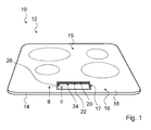
- FIG. 1 shows a designed as an induction hob home appliance 10 with a designed as an induction hob device household appliance device 12.
- the home appliance device 12 has a transparent plate unit 14.
- the plate unit 14 has a portion 16 on which a coating 18 is arranged.
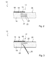
- the plate unit 14 has three structurings 20, 22, 24 which are arranged in an interior of the plate unit 14 along an edge 17 of the partial region 16 ( FIG. 2 ).
- the coating 18 forms an outer surface 15.
- the coating 18 is arranged on an upper side of the plate unit 14.
- the coating 18 is formed by enamel.
- the sub-area 16 frames a viewing area 26.
- the edge 17 forms a border of the viewing area 26.
- Under the plate unit 14, a touch display (not shown) is arranged in the viewing area 26, which leads to an operation of the domestic appliance 10 or an adjustment of heating powers of cooking zones is provided.
- the portion 16 is formed except for the viewing area 26 from the top of the disk unit 14.
- the structurings 20, 22, 24 are each arranged at 60% in the subregion 16.
- the structurings 20, 22, 24 are each arranged 40% outside the partial region 16.
- the structurings 20, 22, 24 each have, across the edge 17, an extension which is greater than a thickness of the plate unit 14.
- the structurings 20, 22, 24 each have an extension transverse to the edge 17 which is smaller than a double one a thickness of the disk unit 14.
- the disk unit 14 has a thickness of 4 mm.
- the structuring 20, 22, 24 are each formed like a ribbon.
- the structurings 20, 22, 24 each form an area that appears at least closed.
- the basic shape of the plate unit 14 is first prepared and the portion 16 of the plate unit 14 is provided with the coating 18.
- the coating 18 is produced by applying a thin layer of frits into the partial region 16, wherein the frits are advantageously embedded in a carrier mass, in particular a solution. By heating, the carrier mass is evaporated and the frits are fused together. Subsequently, ie after the coating 18, the structurings 20, 22, 24 are introduced into the plate unit 14 by means of a laser beam 28.
- the laser beam 28 penetrates from a side facing away from the coating 18 side of the disk unit 14.
- the structurings 20, 22, 24 are produced in sequence, wherein the structurings 20, 22, which are closer to the coating 18, are introduced in front of the structurings 22, 24, which are farther from the coating 18. In this case, lateral positions of the structuring 20, 22, 24 are adapted to a position of the coating 18, so that positional deviations of the coating 18 are compensated.
- the structurings 20, 22, 24 are formed congruent with each other in their shape and their position.
- a clearly demarcated window can be created by the structurings 20, 22, 24, as a result of which any slight irregularities present on a boundary of the coating 18 can be concealed.
- the structurings which lie closer to the coating have a lower area continuity and thus a higher direct transparency than structurings which are farther from the coating.
- the structuring be introduced by laser or another method before applying the coating.
- the structurings have the same width, with structurings that are farther away from the coating, with a larger proportion in the partial area and / or that the structurings have different widths, wherein an equally wide area of the respective areas Structuring lies outside of the subarea and wherein structurings that are farther away from the coating than others of the structurings have a wider area that lies in the subarea.
Landscapes
- Chemical & Material Sciences (AREA)
- Engineering & Computer Science (AREA)
- Combustion & Propulsion (AREA)
- Mechanical Engineering (AREA)
- General Engineering & Computer Science (AREA)
- Physics & Mathematics (AREA)
- Optics & Photonics (AREA)
- Health & Medical Sciences (AREA)
- Toxicology (AREA)
- Life Sciences & Earth Sciences (AREA)
- Chemical Kinetics & Catalysis (AREA)
- General Chemical & Material Sciences (AREA)
- Geochemistry & Mineralogy (AREA)
- Materials Engineering (AREA)
- Organic Chemistry (AREA)
- Induction Heating Cooking Devices (AREA)
- Electric Ovens (AREA)
Abstract
Description
- Die Erfindung geht aus von einer Hausgerätevorrichtung nach dem Oberbegriff des Anspruchs 1.
- Es ist bekannt, Kochplatten mit Beschichtungen zu versehen, wobei Bereiche der Kochfeldplatte, unter denen ein Display angeordnet ist, freigelassen werden.
- Die Aufgabe der Erfindung besteht insbesondere darin, eine gattungsgemäße Vorrichtung mit verbesserten Eigenschaften hinsichtlich eines verbesserten Komforts bereitzustellen. Die Aufgabe wird erfindungsgemäß durch die Merkmale des Patentanspruchs 1 gelöst, während vorteilhafte Ausgestaltungen und Weiterbildungen der Erfindung den Unteransprüchen entnommen werden können.
- Die Erfindung geht aus von einer Hausgerätevorrichtung, insbesondere einer Kochfeldvorrichtung, mit zumindest einer zumindest teilweise transparenten Platteneinheit, die zumindest einen Teilbereich aufweist, der für eine Beschichtung vorgesehen ist.
- Es wird vorgeschlagen, dass die Platteneinheit zumindest eine Strukturierung aufweist, die in einem Inneren der Platteneinheit entlang zumindest eines Teils zumindest eines Randes des Teilbereichs angeordnet ist. Insbesondere ist in dem zumindest einen Teilbereich eine Beschichtung angeordnet. Vorzugsweise bildet der Rand des Teilbereichs einen Rand der Beschichtung. Unter einer "Hausgerätevorrichtung" soll insbesondere ein, insbesondere funktionstüchtiger, Bestandteil, insbesondere eine Konstruktions- und/oder Funktionskomponente, eines Hausgeräts verstanden werden. Unter einem "Hausgerät" soll insbesondere ein, insbesondere elektrisches, alternativ und/oder zusätzlich gas- und/oder ölbetriebenes, Gerät verstanden werden, das dazu vorgesehen ist, in einem Haushalt eingesetzt zu werden, insbesondere eine Hausarbeit, vorteilhaft einen Garvorgang und/oder einen Reinigungsvorgang, zu verrichten und/oder zu unterstützen und/oder das dazu vorgesehen ist, Lebensmittel, insbesondere unter kontrollierten Bedingungen, aufzubewahren. Unter einer "Platteneinheit" soll insbesondere eine Einheit verstanden werden, die eine Dicke aufweist, die maximal 20 %, insbesondere maximal 10 %, vorteilhaft maximal 3 %, vorzugsweise maximal 1 %, einer Länge und einer Breite der Einheit entspricht. Unter einer "Dicke" der Platteneinheit soll insbesondere eine kürzeste Seitenkante eines kleinsten gedachten Quaders, der die Platteneinheit komplett umfasst, verstanden werden. Unter der "Länge" bzw. der "Breite" der Platteneinheit sollen insbesondere die Längen der weiteren Seitenkanten des kleinsten gedachten Quaders verstanden werden. Insbesondere weist die Platteneinheit eine Dicke auf, die kleiner ist als 2 cm, insbesondere kleiner ist als 1 cm, vorteilhaft kleiner ist als 0,5 cm. Darunter, dass die Platteneinheit zumindest teilweise "transparent" ist, soll insbesondere verstanden werden, dass die Platteneinheit in zumindest einer Richtung, insbesondere zumindest im Wesentlichen parallel zur Dicke, und in zumindest einem räumlichen Bereich, insbesondere in jedem räumlichen Bereich, in zumindest einem Wellenlängenbereich, insbesondere für zumindest 10 %, vorteilhaft für zumindest 30 %, besonders vorteilhaft für zumindest 60 %, vorzugsweise für zumindest 95 %, des sichtbaren Lichts zwischen 380 nm und 780 nm eine Transparenz von zumindest 10 %, insbesondere zumindest 30 %, vorteilhaft zumindest 50 %, vorzugsweise zumindest 70 % aufweist, wobei "Transparenz" insbesondere den Anteil des Lichts bezeichnet, der gestreut und/oder auf direktem Weg durch die Platteneinheit dringt. Insbesondere ist die Platteneinheit zumindest teilweise transluzent ausgebildet. Insbesondere ist die Platteneinheit aus einem zumindest glasartigen Material, insbesondere aus Glaskeramik und/oder Borosilikatglas, alternativ aus Fensterglas, Sicherheitsglas, Plexiglas und/oder anderem, einem Fachmann als geeignet erscheinenden Material, gebildet. Insbesondere ist die Platteneinheit zumindest im Wesentlichen von einem klaren Material gebildet. Insbesondere ist der Teilbereich von einem Teil einer Oberfläche der Platteneinheit gebildet. Unter einer "Beschichtung" soll insbesondere eine aus einer einzelnen Schicht oder aus mehreren Schichten gebildete Struktur verstanden werden, die auf die Platteneinheit, insbesondere mittels eines Druckverfahrens, eines Sprühverfahrens und/oder mittels eines physikalischen und/oder chemischen Abscheideverfahrens, aufgebracht ist. Insbesondere weist die Beschichtung eine Dicke auf, die maximal 30 %, insbesondere maximal 10 %, vorteilhaft maximal 3 %, vorzugsweise maximal 1 %, einer Dicke der Platteneinheit entspricht. Vorzugsweise weist die Beschichtung zumindest im Bereich des sichtbaren Lichts eine Transparenz von maximal 30 %, insbesondere maximal 10 %, vorteilhaft maximal 3 %, auf. Unter einer "Strukturierung" soll insbesondere ein mit bloßem Auge wahrnehmbares Objekt verstanden werden. Insbesondere ist die Strukturierung als ein-, zwei- und/oder dreidimensionales, insbesondere linienartiges und/oder flächiges, Objekt, das insbesondere zumindest im Wesentlichen parallel zu der Beschichtung angeordnet ist, ausgebildet. Insbesondere ist die Strukturierung dazu vorgesehen, eine Transparenz der Platteneinheit quer zur Strukturierung zu verringern. Insbesondere ist die Strukturierung dazu vorgesehen, eine Lichtstreuung zu vergrößern. Darunter, dass die Strukturierung in einem "Inneren" der Platteneinheit angeordnet ist, soll insbesondere verstanden werden, dass die Strukturierung zumindest im Wesentlichen ringsum von Material der Platteneinheit umgeben, insbesondere umschlossen, ist. Unter einem "Rand" des Teilbereichs soll insbesondere eine Gruppe von zumindest einer Fläche verstanden werden, die in einer, vorzugsweise orthogonalen, Projektion auf eine Oberfläche von der der Teilbereich gebildet, zumindest eine Begrenzungslinie des Teilbereichs bildet. Darunter, dass die Struktur "entlang" eines Teilstücks des Rands angeordnet ist, soll insbesondere verstanden werden, dass die Struktur den Rand innerhalb des Teilstücks mit Abständen von maximal 5 mm, insbesondere maximal 1 mm, vorteilhaft maximal 0,3 mm, vorzugsweise maximal 0,1 mm, zumindest punktuell schneidet. Vorzugsweise folgt die Struktur dem Rand des Teilbereichs. Insbesondere ist die Struktur maximal 10 cm, insbesondere maximal 5 cm, vorteilhaft maximal 2 cm, besonders vorteilhaft maximal 1 cm, von dem Rand entfernt. Insbesondere erstreckt sich die Struktur, insbesondere kontinuierlich, entlang zumindest 3 cm, insbesondere zumindest 10 cm, vorteilhaft zumindest 20 cm, des Rands. Insbesondere weist die Platteneinheit zumindest zwei, insbesondere zumindest drei, vorteilhaft zumindest vier, Strukturen auf, die in einem Inneren der Platteneinheit angeordnet sind, wobei zumindest zwei der Strukturen in unterschiedlichen Abständen zu einer Oberfläche der Platteneinheit angeordnet sind. Unter "vorgesehen" soll insbesondere speziell ausgeformt, ausgelegt und/oder ausgestattet verstanden werden. Darunter, dass ein Objekt zu einer bestimmten Funktion vorgesehen ist, soll insbesondere verstanden werden, dass das Objekt diese bestimmte Funktion in zumindest einem Anwendungs- und/oder Betriebszustand erfüllt und/oder ausführt.
- Alternativ und/oder zusätzlich wird eine Hausgerätevorrichtung mit zumindest einer zumindest teilweise transparenten Platteneinheit, die zumindest einen Teilbereich aufweist, der für eine Beschichtung vorgesehen ist, vorgeschlagen, wobei die Platteneinheit zumindest eine Strukturierung, insbesondere eine Beschichtung und/oder eine Laserbearbeitung, aufweist, die an einer dem Teilbereich gegenüberliegenden Seite der Platteneinheit entlang zumindest eines Teils zumindest eines Randes des Teilbereichs angeordnet ist.
- Durch die erfindungsgemäße Ausgestaltung kann insbesondere ein hoher Komfort erreicht werden. Insbesondere kann eine verbesserte gestalterische Freiheit erreicht werden. Insbesondere kann ein schräger Einblick in einen Bereich, der hinter dem mit der Beschichtung versehenen Teilbereich liegt, vermieden werden. Es kann insbesondere eine Hervorhebung eines Funktionsbereichs, insbesondere eines Eingabe- und/oder Anzeigebereichs verbessert werden.
- Weiterhin wird vorgeschlagen, dass die Beschichtung eine Außenfläche bildet. Insbesondere ist die Beschichtung auf einer Sichtseite der der Platteneinheit angeordnet ist. Unter einer "Außenfläche" soll insbesondere eine Fläche der Hausgerätevorrichtung verstanden werden, die insbesondere in zumindest einem normalen Betriebszustand, der sich insbesondere von einem Betriebszustand mit geöffneter Hausgerätetür unterscheidet und/oder in dem ein die Hausgerätevorrichtung aufweisendes Hausgerät in einer Einbaunische untergebracht ist, in einem Sichtfeld eines Bedieners liegt und/oder die unmittelbar berührt werden kann. Es kann insbesondere eine optisch ansprechende Ausgestaltung erreicht werden. Insbesondere findet die erfindungsgemäße Ausgestaltung besonders vorteilhaften Einsatz.
- Ferner wird vorgeschlagen, dass der zumindest eine Teilbereich einen Sichtbereich zumindest im Wesentlichen umrahmt. Unter einem "Sichtbereich" soll insbesondere ein Bereich verstanden werden, der dazu vorgesehen ist, einem Bediener von außen Einblick in einen Bereich hinter der Platteneinheit, insbesondere auf eine Bedienerschnittstelle und/oder in einen Funktionsraum, insbesondere Garraum, Waschraum, Lagerraum oder Ähnliches, zu gewähren. Insbesondere ist die Strukturierung dazu vorgesehen, den Sichtbereich zumindest im Wesentlichen einzurahmen. Es kann insbesondere eine vorteilhafte Anwendung der Erfindung erreicht werden. Es kann insbesondere ein hoher Komfort erreicht werden.
- Weiterhin wird vorgeschlagen, dass die Strukturierung mittels eines Laserstrahls gebildet ist. Insbesondere ist die Strukturierung als Laserinnengravur ausgebildet. Insbesondere ist die Strukturierung von durch zumindest einen Laserstrahl manipuliertem Material der Platteneinheit gebildet. Insbesondere ist die Strukturierung von Gasbläschen gebildet, die durch Laserbeschuss in dem Material der Platteneinheit erzeugt wurden. Es kann insbesondere eine flexible, einfache, effiziente und/oder kostengünstige Ausgestaltung erreicht werden. Alternativ ist es denkbar, dass die Strukturierung bei einer Erzeugung der Platteneinheit, beispielsweise durch Einbringung von Fremdmaterial in diese, erzeugt wird. Weiterhin ist es denkbar, dass die Strukturierung durch Ionenstrahlen, insbesondere lonenstrahlimplantation, bei der insbesondere neben Fremdmaterial Energie eingebracht wird, erzeugt ist.
- Ferner wird vorgeschlagen, dass die Strukturierung zumindest teilweise, insbesondere zu mindestens 30 %, vorteilhaft zu mindestens 50 %, besonders vorteilhaft zu mindestens 70 %, vorzugsweise zu mindestens 90 %, in dem Teilbereich angeordnet ist. Darunter, dass ein Teil der Strukturierung "in" dem Teilbereich angeordnet ist, soll insbesondere verstanden werden, dass dieser Teil in einer, vorzugsweise orthogonalen, Projektion auf eine den Teilbereich aufweisenden Oberfläche, in dem Teilbereich liegt. Es kann insbesondere eine gute Sichtversperrung, insbesondere bei schrägem Einblick, erreicht werden.
- Weiterhin wird vorgeschlagen, dass die Strukturierung zumindest teilweise, insbesondere zu mindestens 10 %, vorteilhaft zu mindestens 20 %, vorteilhaft zu mindestens 30 %, und/oder zu maximal 50 %, insbesondere zu maximal 30 %, außerhalb des Teilbereichs, insbesondere im Sichtbereich, angeordnet ist. Darunter, dass ein Teil der Strukturierung "außerhalb" des Teilbereichs angeordnet ist, soll insbesondere verstanden werden, dass dieser Teil in einer, vorzugsweise orthogonalen, Projektion auf eine den Teilbereich aufweisende Oberfläche, außerhalb des Teilbereichs liegt. Insbesondere ist es denkbar, dass eine erste Strukturierung, die von der Oberfläche mit dem Teilbereich weiter entfernt ist, als eine zweite Strukturierung einen größeren Anteil aufweist, der in dem Teilbereich liegt, als die zweite Strukturierung. Es kann insbesondere ein optisch angenehmer Übergang zwischen dem Teilbereich und dem Sichtbereich erreicht werden.
- Ferner wird vorgeschlagen, dass die Beschichtung zumindest im Wesentlichen von einem zumindest emailartigen Material gebildet ist. Unter einem "emailartigen" Material soll insbesondere ein Material verstanden werden, dass zumindest in einem ausgehärteten Zustand ein glasartiges und/oder emailnes Erscheinungsbild aufweist. Insbesondere ist die Beschichtung aus geschmolzenen Glas- und/oder Keramikfritten gebildet, die auf den Teilbereich aufgebracht und zu einer einheitlichen Schicht verschmolzen wurden. Es kann insbesondere eine homogene und/oder harte Oberfläche erreicht werden. Insbesondere kann eine hohe Farbenvielfalt der Oberfläche erreicht werden. Insbesondere kann ein keramischer Anschein der Platteneinheit erzeugt werden. Insbesondere kann eine hohe Gesamtsteifigkeit und/oder -flexibilität der Platteneinheit erreicht werden. Alternativ sind Ausgestaltungen denkbar, wobei die Beschichtung aus einem, vorzugsweise thermisch, insbesondere bis zu Temperaturen von 300 °C, stabilen, Polymer, insbesondere einem Harz, gebildet. Vorzugsweise weist die Beschichtung einen Härtegrad nach Mohs von zumindest 5, vorteilhaft zumindest 6, vorzugsweise zumindest 7 , auf.
- Es werden Hausgeräte vorgeschlagen, die eine erfindungsgemäße Hausgerätevorrichtung aufweisen. Vorteilhaft ist die Platteneinheit als Kochfeldplatte ausgebildet. Alternativ ist es denkbar, dass die Platteneinheit als Türeinheit ausgebildet ist, wobei die Strukturierung insbesondere dazu vorgesehen ist, einen Einblick in eine Türkonstruktion und/oder-aufhängung zu vermeiden. Insbesondere ist das Hausgerät als Gargerät, insbesondere Backofen und/oder Mikrowellenofen, als Waschgerät, insbesondere als Waschmaschine, Wäschetrockner und/oder Geschirrspüler, oder als Lagergerät, insbesondere als Kühl- und/oder Gefriergerät, ausgebildet.
- Weitere Vorteile ergeben sich aus der folgenden Zeichnungsbeschreibung. In der Zeichnung ist ein Ausführungsbeispiel der Erfindung dargestellt. Die Zeichnung, die Beschreibung und die Ansprüche enthalten zahlreiche Merkmale in Kombination. Der Fachmann wird die Merkmale zweckmäßigerweise auch einzeln betrachten und zu sinnvollen weiteren Kombinationen zusammenfassen.
- Es zeigen in schematischer Ansicht:
- Fig. 1
- ein erfindungsgemäßes Induktionskochfeld mit einer erfindungsgemäßen Kochfeldvorrichtung in einer Ansicht von oben,
- Fig. 2
- eine Darstellung eines Schnitts durch die Kochfeldvorrichtung entlang der Linie II-II in
Figur 1 und - Fig. 3
- einen Herstellungsschritt einer erfindungsgemäßen Kochfeldvorrichtung.
-
Figur 1 zeigt ein als Induktionskochfeld ausgebildetes Hausgerät 10 mit einer als Induktionskochfeldvorrichtung ausgebildeten Hausgerätevorrichtung 12. Die Hausgerätevorrichtung 12 weist eine transparente Platteneinheit 14 auf. Die Platteneinheit 14 weist einen Teilbereich 16 auf, auf dem eine Beschichtung 18 angeordnet ist. Die Platteneinheit 14 weist drei Strukturierungen 20, 22, 24 auf, die in einem Inneren der Platteneinheit 14 entlang eines Randes 17 des Teilbereichs 16 angeordnet ist (Figur 2 ). - Die Beschichtung 18 bildet eine Außenfläche 15 aus. Die Beschichtung 18 ist auf einer Oberseite der Platteneinheit 14 angeordnet. Die Beschichtung 18 ist von Email gebildet. Der Teilbereich 16 umrahmt einen Sichtbereich 26. Der Rand 17 bildet eine Umrandung des Sichtbereichs 26. Unter der Platteneinheit 14 ist in dem Sichtbereich 26 ein Touch-Display angeordnet (nicht dargestellt), das zu einer Bedienung des Hausgeräts 10 bzw. einer Einstellung von Heizleistungen von Kochzonen vorgesehen ist. Der Teilbereich 16 ist bis auf den Sichtbereich 26 von der Oberseite der Platteneinheit 14 gebildet.
- Die Strukturierungen 20, 22, 24 sind jeweils zu 60 % in dem Teilbereich 16 angeordnet. Die Strukturierungen 20, 22, 24 sind jeweils zu 40 % außerhalb des Teilbereichs 16 angeordnet. Die Strukturierungen 20, 22, 24 weisen quer zum Rand 17 jeweils eine Erstreckung auf, die größer ist als eine Dicke der Platteneinheit 14. Die Strukturierungen 20, 22, 24 weisen quer zum Rand 17 jeweils eine Erstreckung auf, die kleiner ist als ein doppeltes einer Dicke der Platteneinheit 14. Die Platteneinheit 14 weist eine Dicke von 4 mm auf. Die Strukturierungen 20, 22, 24 sind jeweils bandartig ausgebildet. Die Strukturierungen 20, 22, 24 bilden jeweils eine zumindest geschlossen erscheinende Fläche.
- Bei einer Herstellung wird zuerst die Grundform der Platteneinheit 14 hergestellt und der Teilbereich 16 der Platteneinheit 14 mit der Beschichtung 18 versehen. Die Beschichtung 18 wird hergestellt durch Aufbringen einer dünnen Schicht Fritten in den Teilbereich 16, wobei die Fritten vorteilhaft in einer Trägermasse, insbesondere einer Lösung, eingebettet sind. Durch Erhitzen wird die Trägermasse verdampft und die Fritten miteinander verschmolzen. Anschließend, also nach der Beschichtung 18, werden die Strukturierungen 20, 22, 24 mittels eines Laserstrahls 28 in die Platteneinheit 14 eingebracht. Der Laserstrahl 28 dringt dabei von einer von der Beschichtung 18 abgewandten Seite der Platteneinheit 14 ein. Die Strukturierungen 20, 22, 24 werden der Reihe nach erzeugt, wobei die Strukturierungen 20, 22, die näher an der Beschichtung 18 liegen, vor den Strukturierungen 22, 24, die weiter von der Beschichtung 18 entfernt sind, eingebracht werden. Dabei werden laterale Positionen der Strukturierungen 20, 22, 24 an eine Position der Beschichtung 18 angepasst, so dass Positionsabweichungen der Beschichtung 18 ausgeglichen werden. Die Strukturierungen 20, 22, 24 sind in ihrer Form und ihrer Position deckungsgleich zueinander ausgebildet.
- Weiterhin kann durch die Strukturierungen 20, 22, 24 ein klar abgegrenztes Fenster geschaffen werden, wodurch eventuell vorhandene leichte Unregelmäßigkeiten an einer Berandung der Beschichtung 18 verdeckt werden können.
- In weiteren Ausgestaltungen ist es denkbar, dass die Strukturierungen, die näher an der Beschichtung liegen, eine geringere Flächenkontinuität und somit eine höhere direkte Transparenz aufweisen als Strukturierungen, die weiter von der Beschichtung entfernt sind.
- Ferner ist es denkbar, dass die Strukturierung durch Laser oder ein anderes Verfahren vor einem Aufbringen der Beschichtung eingebracht werden.
- Weiterhin ist es denkbar, dass die Strukturierungen, eine gleiche Breite aufweisen, wobei Strukturierungen, die weiter von der Beschichtung entfernt sind, mit einem größeren Anteil in dem Teilbereich liegen und/oder dass die Strukturierungen unterschiedliche Breiten aufweisen, wobei ein jeweils gleich breiter Bereich der Strukturierungen außerhalb des Teilbereichs liegt und wobei Strukturierungen, die weiter von der Beschichtung entfernt sind als andere der Strukturierungen, einen breiteren Bereich aufweisen, der in dem Teilbereich liegt.
-
- 10
- Hausgerät
- 12
- Hausgerätevorrichtung
- 14
- Platteneinheit
- 15
- Außenfläche
- 16
- Teilbereich
- 17
- Rand
- 18
- Beschichtung
- 20
- Strukturierung
- 22
- Strukturierung
- 24
- Strukturierung
- 26
- Sichtbereich
- 28
- Laserstrahl
Claims (10)
- Hausgerätevorrichtung, insbesondere Kochfeldvorrichtung, mit zumindest einer zumindest teilweise transparenten Platteneinheit (14), die zumindest einen Teilbereich (16) aufweist, der für eine Beschichtung (18) vorgesehen ist, dadurch gekennzeichnet, dass die Platteneinheit (14) zumindest eine Strukturierung (20, 22, 24) aufweist, die in einem Inneren der Platteneinheit (14) entlang zumindest eines Teils zumindest eines Randes (17) des Teilbereichs (16) angeordnet ist.
- Hausgerätevorrichtung nach Anspruch 1, dadurch gekennzeichnet, dass die Beschichtung (18) eine Außenfläche (15) ausbildet.
- Hausgerätevorrichtung nach einem der vorhergehenden Ansprüche, dadurch gekennzeichnet, dass der zumindest eine Teilbereich (16) einen Sichtbereich (26) umrahmt.
- Hausgerätevorrichtung nach einem der vorhergehenden Ansprüche, dadurch gekennzeichnet, dass die Strukturierung (20, 22, 24) mittels eines Laserstrahls (28) gebildet ist.
- Hausgerätevorrichtung nach einem der vorhergehenden Ansprüche, dadurch gekennzeichnet, dass die Strukturierung (20, 22, 24) zumindest teilweise in dem Teilbereich (16) angeordnet ist.
- Hausgerätevorrichtung nach einem der vorhergehenden Ansprüche, dadurch gekennzeichnet, dass die Strukturierung (20, 22, 24) zumindest teilweise außerhalb des Teilbereichs (16) angeordnet ist.
- Hausgerätevorrichtung nach einem der vorhergehenden Ansprüche, dadurch gekennzeichnet, dass die Beschichtung (18) zumindest im Wesentlichen von einem zumindest emailartigen Material gebildet ist.
- Hausgerät, insbesondere Kochfeld, mit einer Hausgerätevorrichtung (12) nach einem der vorhergehenden Ansprüche.
- Verfahren zur Herstellung einer Hausgerätevorrichtung (12) nach einem der Ansprüche 1 bis 7.
- Verfahren nach Anspruch 9, dadurch gekennzeichnet, dass die Strukturierung (20, 22, 24) nach Aufbringung der Beschichtung (18) erzeugt wird.
Priority Applications (1)
| Application Number | Priority Date | Filing Date | Title |
|---|---|---|---|
| EP13382020.9A EP2757079B1 (de) | 2013-01-21 | 2013-01-21 | Kochfeldvorrichtung |
Applications Claiming Priority (1)
| Application Number | Priority Date | Filing Date | Title |
|---|---|---|---|
| EP13382020.9A EP2757079B1 (de) | 2013-01-21 | 2013-01-21 | Kochfeldvorrichtung |
Publications (2)
| Publication Number | Publication Date |
|---|---|
| EP2757079A1 true EP2757079A1 (de) | 2014-07-23 |
| EP2757079B1 EP2757079B1 (de) | 2020-04-22 |
Family
ID=47632951
Family Applications (1)
| Application Number | Title | Priority Date | Filing Date |
|---|---|---|---|
| EP13382020.9A Active EP2757079B1 (de) | 2013-01-21 | 2013-01-21 | Kochfeldvorrichtung |
Country Status (1)
| Country | Link |
|---|---|
| EP (1) | EP2757079B1 (de) |
Citations (5)
| Publication number | Priority date | Publication date | Assignee | Title |
|---|---|---|---|---|
| DE202006004064U1 (de) * | 2006-03-13 | 2006-07-27 | Secqtec Gmbh & Co. Kg | Laserbeschriftete Glaskeramikscheiben |
| EP1867613A1 (de) * | 2006-06-16 | 2007-12-19 | Schott AG | Kochfeld mit einer Glaskeramikplatte als Kochfläche |
| EP2236312A2 (de) * | 2009-04-03 | 2010-10-06 | BSH Bosch und Siemens Hausgeräte GmbH | Platte mit einem durchsichtigen Grundkörper für ein Haushaltsgerät und Verfahren zur Herstellung der Platte |
| WO2011020718A1 (de) * | 2009-08-17 | 2011-02-24 | BSH Bosch und Siemens Hausgeräte GmbH | Hausgeräte-abdeckplatte mit fabry-perot interferenzschicht |
| WO2012131511A1 (de) * | 2011-03-30 | 2012-10-04 | BSH Bosch und Siemens Hausgeräte GmbH | Kochfeldplatte mit einer an der unterseite angebrachten beschichtung |
Family Cites Families (2)
| Publication number | Priority date | Publication date | Assignee | Title |
|---|---|---|---|---|
| DE102010045149A1 (de) * | 2010-09-11 | 2012-03-15 | Bayer Material Science Ag | Beschichtung auf Polyurethanbasis für Anzeigebereiche |
| DE102012206930A1 (de) * | 2011-05-03 | 2012-11-08 | BSH Bosch und Siemens Hausgeräte GmbH | Hausgeräteplatte |
-
2013
- 2013-01-21 EP EP13382020.9A patent/EP2757079B1/de active Active
Patent Citations (5)
| Publication number | Priority date | Publication date | Assignee | Title |
|---|---|---|---|---|
| DE202006004064U1 (de) * | 2006-03-13 | 2006-07-27 | Secqtec Gmbh & Co. Kg | Laserbeschriftete Glaskeramikscheiben |
| EP1867613A1 (de) * | 2006-06-16 | 2007-12-19 | Schott AG | Kochfeld mit einer Glaskeramikplatte als Kochfläche |
| EP2236312A2 (de) * | 2009-04-03 | 2010-10-06 | BSH Bosch und Siemens Hausgeräte GmbH | Platte mit einem durchsichtigen Grundkörper für ein Haushaltsgerät und Verfahren zur Herstellung der Platte |
| WO2011020718A1 (de) * | 2009-08-17 | 2011-02-24 | BSH Bosch und Siemens Hausgeräte GmbH | Hausgeräte-abdeckplatte mit fabry-perot interferenzschicht |
| WO2012131511A1 (de) * | 2011-03-30 | 2012-10-04 | BSH Bosch und Siemens Hausgeräte GmbH | Kochfeldplatte mit einer an der unterseite angebrachten beschichtung |
Also Published As
| Publication number | Publication date |
|---|---|
| EP2757079B1 (de) | 2020-04-22 |
Similar Documents
| Publication | Publication Date | Title |
|---|---|---|
| WO2006076972A1 (de) | Hausgeräteeinstelleinheit | |
| EP2573204A1 (de) | Verfahren zur Herstellung einer Hausgeräteplatte | |
| DE102007028543A1 (de) | Vogelschutzvorrichtung | |
| WO2010023073A2 (de) | Haushaltsgerät, insbesondere dunstabzugsvorrichtung oder gargerät, sowie verfahren zu dessen herstellung | |
| EP2333421B1 (de) | Anzeigeflächenelement für ein Hausgerät | |
| EP2072478A1 (de) | Hausgerätebauteil und Verfahren zum Bearbeiten eines Hausgerätebauteils | |
| DE102004015751A1 (de) | Haushaltsgerät, insbesondere Gargerät | |
| DE102004044183A1 (de) | Verblendungsteil für Haushaltsgerät, Haushaltsgerät und Verfahren zur Herstellung eines Verblendungsteils | |
| EP3064119A1 (de) | Haushaltgerät mit berührungsempfindlicher anzeige | |
| EP2757079B1 (de) | Kochfeldvorrichtung | |
| EP2757319A1 (de) | Hausgerätevorrichtung | |
| DE102014214105A1 (de) | Hausgerätekomponentenherstellverfahren zur Herstellung einer Hausgerätekomponente und Hausgerätekomponente | |
| EP3853528A1 (de) | Haushaltsgerät mit einem rauheitsreduzierungselement in einer vertiefung einer komponente aus einem transparenten material, sowie verfahren zum herstellen eines haushaltsgeräts | |
| EP2063179B1 (de) | Bedieneinheit für ein Hausgerät und Verfahren zum Herstellen einer Bedieneinheit | |
| EP2757321B1 (de) | Kochfeld | |
| WO2012085821A1 (de) | Hausgerätevorrichtung | |
| EP2236312A2 (de) | Platte mit einem durchsichtigen Grundkörper für ein Haushaltsgerät und Verfahren zur Herstellung der Platte | |
| DE102019215458B4 (de) | Anzeigevorrichtung für ein Haushaltsgerät, Haushaltsgerät mit Anzeigevorrichtung und Herstellungsverfahren für eine Anzeigevorrichtung | |
| WO2012028986A1 (de) | Haushaltsgerät mit einer aus einem durchsichtigen material ausgebildeten platte sowie verfahren zum herstellen einer derartigen platte | |
| EP1283105A1 (de) | Frontblende eines Elektrogerätes | |
| EP2573203A1 (de) | Verfahren zur Herstellung einer Hausgeräteplatte | |
| EP3182017B1 (de) | Haushaltgerät | |
| DE102012206930A1 (de) | Hausgeräteplatte | |
| DE102007031479A1 (de) | Haushaltsgerät mit einem Bedienmodul | |
| EP2757320B1 (de) | Kochfeldvorrichtung mit mehreren Beschichtung |
Legal Events
| Date | Code | Title | Description |
|---|---|---|---|
| PUAI | Public reference made under article 153(3) epc to a published international application that has entered the european phase |
Free format text: ORIGINAL CODE: 0009012 |
|
| 17P | Request for examination filed |
Effective date: 20130121 |
|
| AK | Designated contracting states |
Kind code of ref document: A1 Designated state(s): AL AT BE BG CH CY CZ DE DK EE ES FI FR GB GR HR HU IE IS IT LI LT LU LV MC MK MT NL NO PL PT RO RS SE SI SK SM TR |
|
| AX | Request for extension of the european patent |
Extension state: BA ME |
|
| R17P | Request for examination filed (corrected) |
Effective date: 20150123 |
|
| RBV | Designated contracting states (corrected) |
Designated state(s): AL AT BE BG CH CY CZ DE DK EE ES FI FR GB GR HR HU IE IS IT LI LT LU LV MC MK MT NL NO PL PT RO RS SE SI SK SM TR |
|
| RAP1 | Party data changed (applicant data changed or rights of an application transferred) |
Owner name: BSH HAUSGERAETE GMBH |
|
| 17Q | First examination report despatched |
Effective date: 20160420 |
|
| STAA | Information on the status of an ep patent application or granted ep patent |
Free format text: STATUS: EXAMINATION IS IN PROGRESS |
|
| REG | Reference to a national code |
Ref country code: DE Ref legal event code: R079 Ref document number: 502013014614 Country of ref document: DE Free format text: PREVIOUS MAIN CLASS: C03C0023000000 Ipc: F24C0015100000 |
|
| GRAP | Despatch of communication of intention to grant a patent |
Free format text: ORIGINAL CODE: EPIDOSNIGR1 |
|
| STAA | Information on the status of an ep patent application or granted ep patent |
Free format text: STATUS: GRANT OF PATENT IS INTENDED |
|
| INTG | Intention to grant announced |
Effective date: 20191122 |
|
| RIC1 | Information provided on ipc code assigned before grant |
Ipc: F24C 15/10 20060101AFI20191108BHEP Ipc: C03C 23/00 20060101ALI20191108BHEP |
|
| GRAS | Grant fee paid |
Free format text: ORIGINAL CODE: EPIDOSNIGR3 |
|
| GRAA | (expected) grant |
Free format text: ORIGINAL CODE: 0009210 |
|
| STAA | Information on the status of an ep patent application or granted ep patent |
Free format text: STATUS: THE PATENT HAS BEEN GRANTED |
|
| AK | Designated contracting states |
Kind code of ref document: B1 Designated state(s): AL AT BE BG CH CY CZ DE DK EE ES FI FR GB GR HR HU IE IS IT LI LT LU LV MC MK MT NL NO PL PT RO RS SE SI SK SM TR |
|
| REG | Reference to a national code |
Ref country code: GB Ref legal event code: FG4D Free format text: NOT ENGLISH |
|
| REG | Reference to a national code |
Ref country code: CH Ref legal event code: EP |
|
| REG | Reference to a national code |
Ref country code: DE Ref legal event code: R096 Ref document number: 502013014614 Country of ref document: DE |
|
| REG | Reference to a national code |
Ref country code: IE Ref legal event code: FG4D Free format text: LANGUAGE OF EP DOCUMENT: GERMAN |
|
| REG | Reference to a national code |
Ref country code: AT Ref legal event code: REF Ref document number: 1260619 Country of ref document: AT Kind code of ref document: T Effective date: 20200515 |
|
| REG | Reference to a national code |
Ref country code: LT Ref legal event code: MG4D |
|
| REG | Reference to a national code |
Ref country code: NL Ref legal event code: MP Effective date: 20200422 |
|
| PG25 | Lapsed in a contracting state [announced via postgrant information from national office to epo] |
Ref country code: FI Free format text: LAPSE BECAUSE OF FAILURE TO SUBMIT A TRANSLATION OF THE DESCRIPTION OR TO PAY THE FEE WITHIN THE PRESCRIBED TIME-LIMIT Effective date: 20200422 Ref country code: SE Free format text: LAPSE BECAUSE OF FAILURE TO SUBMIT A TRANSLATION OF THE DESCRIPTION OR TO PAY THE FEE WITHIN THE PRESCRIBED TIME-LIMIT Effective date: 20200422 Ref country code: LT Free format text: LAPSE BECAUSE OF FAILURE TO SUBMIT A TRANSLATION OF THE DESCRIPTION OR TO PAY THE FEE WITHIN THE PRESCRIBED TIME-LIMIT Effective date: 20200422 Ref country code: NL Free format text: LAPSE BECAUSE OF FAILURE TO SUBMIT A TRANSLATION OF THE DESCRIPTION OR TO PAY THE FEE WITHIN THE PRESCRIBED TIME-LIMIT Effective date: 20200422 Ref country code: PT Free format text: LAPSE BECAUSE OF FAILURE TO SUBMIT A TRANSLATION OF THE DESCRIPTION OR TO PAY THE FEE WITHIN THE PRESCRIBED TIME-LIMIT Effective date: 20200824 Ref country code: GR Free format text: LAPSE BECAUSE OF FAILURE TO SUBMIT A TRANSLATION OF THE DESCRIPTION OR TO PAY THE FEE WITHIN THE PRESCRIBED TIME-LIMIT Effective date: 20200723 Ref country code: NO Free format text: LAPSE BECAUSE OF FAILURE TO SUBMIT A TRANSLATION OF THE DESCRIPTION OR TO PAY THE FEE WITHIN THE PRESCRIBED TIME-LIMIT Effective date: 20200722 Ref country code: IS Free format text: LAPSE BECAUSE OF FAILURE TO SUBMIT A TRANSLATION OF THE DESCRIPTION OR TO PAY THE FEE WITHIN THE PRESCRIBED TIME-LIMIT Effective date: 20200822 |
|
| PG25 | Lapsed in a contracting state [announced via postgrant information from national office to epo] |
Ref country code: RS Free format text: LAPSE BECAUSE OF FAILURE TO SUBMIT A TRANSLATION OF THE DESCRIPTION OR TO PAY THE FEE WITHIN THE PRESCRIBED TIME-LIMIT Effective date: 20200422 Ref country code: BG Free format text: LAPSE BECAUSE OF FAILURE TO SUBMIT A TRANSLATION OF THE DESCRIPTION OR TO PAY THE FEE WITHIN THE PRESCRIBED TIME-LIMIT Effective date: 20200722 Ref country code: LV Free format text: LAPSE BECAUSE OF FAILURE TO SUBMIT A TRANSLATION OF THE DESCRIPTION OR TO PAY THE FEE WITHIN THE PRESCRIBED TIME-LIMIT Effective date: 20200422 Ref country code: HR Free format text: LAPSE BECAUSE OF FAILURE TO SUBMIT A TRANSLATION OF THE DESCRIPTION OR TO PAY THE FEE WITHIN THE PRESCRIBED TIME-LIMIT Effective date: 20200422 |
|
| PG25 | Lapsed in a contracting state [announced via postgrant information from national office to epo] |
Ref country code: AL Free format text: LAPSE BECAUSE OF FAILURE TO SUBMIT A TRANSLATION OF THE DESCRIPTION OR TO PAY THE FEE WITHIN THE PRESCRIBED TIME-LIMIT Effective date: 20200422 |
|
| REG | Reference to a national code |
Ref country code: DE Ref legal event code: R097 Ref document number: 502013014614 Country of ref document: DE |
|
| PG25 | Lapsed in a contracting state [announced via postgrant information from national office to epo] |
Ref country code: DK Free format text: LAPSE BECAUSE OF FAILURE TO SUBMIT A TRANSLATION OF THE DESCRIPTION OR TO PAY THE FEE WITHIN THE PRESCRIBED TIME-LIMIT Effective date: 20200422 Ref country code: IT Free format text: LAPSE BECAUSE OF FAILURE TO SUBMIT A TRANSLATION OF THE DESCRIPTION OR TO PAY THE FEE WITHIN THE PRESCRIBED TIME-LIMIT Effective date: 20200422 Ref country code: EE Free format text: LAPSE BECAUSE OF FAILURE TO SUBMIT A TRANSLATION OF THE DESCRIPTION OR TO PAY THE FEE WITHIN THE PRESCRIBED TIME-LIMIT Effective date: 20200422 Ref country code: SM Free format text: LAPSE BECAUSE OF FAILURE TO SUBMIT A TRANSLATION OF THE DESCRIPTION OR TO PAY THE FEE WITHIN THE PRESCRIBED TIME-LIMIT Effective date: 20200422 Ref country code: RO Free format text: LAPSE BECAUSE OF FAILURE TO SUBMIT A TRANSLATION OF THE DESCRIPTION OR TO PAY THE FEE WITHIN THE PRESCRIBED TIME-LIMIT Effective date: 20200422 Ref country code: CZ Free format text: LAPSE BECAUSE OF FAILURE TO SUBMIT A TRANSLATION OF THE DESCRIPTION OR TO PAY THE FEE WITHIN THE PRESCRIBED TIME-LIMIT Effective date: 20200422 Ref country code: ES Free format text: LAPSE BECAUSE OF FAILURE TO SUBMIT A TRANSLATION OF THE DESCRIPTION OR TO PAY THE FEE WITHIN THE PRESCRIBED TIME-LIMIT Effective date: 20200422 |
|
| PG25 | Lapsed in a contracting state [announced via postgrant information from national office to epo] |
Ref country code: PL Free format text: LAPSE BECAUSE OF FAILURE TO SUBMIT A TRANSLATION OF THE DESCRIPTION OR TO PAY THE FEE WITHIN THE PRESCRIBED TIME-LIMIT Effective date: 20200422 Ref country code: SK Free format text: LAPSE BECAUSE OF FAILURE TO SUBMIT A TRANSLATION OF THE DESCRIPTION OR TO PAY THE FEE WITHIN THE PRESCRIBED TIME-LIMIT Effective date: 20200422 |
|
| PLBE | No opposition filed within time limit |
Free format text: ORIGINAL CODE: 0009261 |
|
| STAA | Information on the status of an ep patent application or granted ep patent |
Free format text: STATUS: NO OPPOSITION FILED WITHIN TIME LIMIT |
|
| 26N | No opposition filed |
Effective date: 20210125 |
|
| PG25 | Lapsed in a contracting state [announced via postgrant information from national office to epo] |
Ref country code: SI Free format text: LAPSE BECAUSE OF FAILURE TO SUBMIT A TRANSLATION OF THE DESCRIPTION OR TO PAY THE FEE WITHIN THE PRESCRIBED TIME-LIMIT Effective date: 20200422 |
|
| PG25 | Lapsed in a contracting state [announced via postgrant information from national office to epo] |
Ref country code: MC Free format text: LAPSE BECAUSE OF FAILURE TO SUBMIT A TRANSLATION OF THE DESCRIPTION OR TO PAY THE FEE WITHIN THE PRESCRIBED TIME-LIMIT Effective date: 20200422 |
|
| REG | Reference to a national code |
Ref country code: CH Ref legal event code: PL |
|
| GBPC | Gb: european patent ceased through non-payment of renewal fee |
Effective date: 20210121 |
|
| PG25 | Lapsed in a contracting state [announced via postgrant information from national office to epo] |
Ref country code: LU Free format text: LAPSE BECAUSE OF NON-PAYMENT OF DUE FEES Effective date: 20210121 |
|
| REG | Reference to a national code |
Ref country code: BE Ref legal event code: MM Effective date: 20210131 |
|
| PG25 | Lapsed in a contracting state [announced via postgrant information from national office to epo] |
Ref country code: LI Free format text: LAPSE BECAUSE OF NON-PAYMENT OF DUE FEES Effective date: 20210131 Ref country code: GB Free format text: LAPSE BECAUSE OF NON-PAYMENT OF DUE FEES Effective date: 20210121 Ref country code: CH Free format text: LAPSE BECAUSE OF NON-PAYMENT OF DUE FEES Effective date: 20210131 |
|
| PG25 | Lapsed in a contracting state [announced via postgrant information from national office to epo] |
Ref country code: IE Free format text: LAPSE BECAUSE OF NON-PAYMENT OF DUE FEES Effective date: 20210121 |
|
| REG | Reference to a national code |
Ref country code: AT Ref legal event code: MM01 Ref document number: 1260619 Country of ref document: AT Kind code of ref document: T Effective date: 20210121 |
|
| PG25 | Lapsed in a contracting state [announced via postgrant information from national office to epo] |
Ref country code: AT Free format text: LAPSE BECAUSE OF NON-PAYMENT OF DUE FEES Effective date: 20210121 |
|
| PG25 | Lapsed in a contracting state [announced via postgrant information from national office to epo] |
Ref country code: BE Free format text: LAPSE BECAUSE OF NON-PAYMENT OF DUE FEES Effective date: 20210131 |
|
| REG | Reference to a national code |
Ref country code: DE Ref legal event code: R084 Ref document number: 502013014614 Country of ref document: DE |
|
| PG25 | Lapsed in a contracting state [announced via postgrant information from national office to epo] |
Ref country code: HU Free format text: LAPSE BECAUSE OF FAILURE TO SUBMIT A TRANSLATION OF THE DESCRIPTION OR TO PAY THE FEE WITHIN THE PRESCRIBED TIME-LIMIT; INVALID AB INITIO Effective date: 20130121 |
|
| PG25 | Lapsed in a contracting state [announced via postgrant information from national office to epo] |
Ref country code: CY Free format text: LAPSE BECAUSE OF FAILURE TO SUBMIT A TRANSLATION OF THE DESCRIPTION OR TO PAY THE FEE WITHIN THE PRESCRIBED TIME-LIMIT Effective date: 20200422 |
|
| PG25 | Lapsed in a contracting state [announced via postgrant information from national office to epo] |
Ref country code: MK Free format text: LAPSE BECAUSE OF FAILURE TO SUBMIT A TRANSLATION OF THE DESCRIPTION OR TO PAY THE FEE WITHIN THE PRESCRIBED TIME-LIMIT Effective date: 20200422 |
|
| PG25 | Lapsed in a contracting state [announced via postgrant information from national office to epo] |
Ref country code: MT Free format text: LAPSE BECAUSE OF FAILURE TO SUBMIT A TRANSLATION OF THE DESCRIPTION OR TO PAY THE FEE WITHIN THE PRESCRIBED TIME-LIMIT Effective date: 20200422 |
|
| PG25 | Lapsed in a contracting state [announced via postgrant information from national office to epo] |
Ref country code: TR Free format text: LAPSE BECAUSE OF FAILURE TO SUBMIT A TRANSLATION OF THE DESCRIPTION OR TO PAY THE FEE WITHIN THE PRESCRIBED TIME-LIMIT Effective date: 20200422 |
|
| PGFP | Annual fee paid to national office [announced via postgrant information from national office to epo] |
Ref country code: DE Payment date: 20260131 Year of fee payment: 14 |
|
| PGFP | Annual fee paid to national office [announced via postgrant information from national office to epo] |
Ref country code: FR Payment date: 20260127 Year of fee payment: 14 |