EP2756955A1 - Liquid discharge device and liquid transport method - Google Patents
Liquid discharge device and liquid transport method Download PDFInfo
- Publication number
- EP2756955A1 EP2756955A1 EP12831492.9A EP12831492A EP2756955A1 EP 2756955 A1 EP2756955 A1 EP 2756955A1 EP 12831492 A EP12831492 A EP 12831492A EP 2756955 A1 EP2756955 A1 EP 2756955A1
- Authority
- EP
- European Patent Office
- Prior art keywords
- ink
- liquid
- flow channel
- unit
- accommodation unit
- Prior art date
- Legal status (The legal status is an assumption and is not a legal conclusion. Google has not performed a legal analysis and makes no representation as to the accuracy of the status listed.)
- Granted
Links
Images



Classifications
-
- B—PERFORMING OPERATIONS; TRANSPORTING
- B41—PRINTING; LINING MACHINES; TYPEWRITERS; STAMPS
- B41J—TYPEWRITERS; SELECTIVE PRINTING MECHANISMS, i.e. MECHANISMS PRINTING OTHERWISE THAN FROM A FORME; CORRECTION OF TYPOGRAPHICAL ERRORS
- B41J2/00—Typewriters or selective printing mechanisms characterised by the printing or marking process for which they are designed
- B41J2/005—Typewriters or selective printing mechanisms characterised by the printing or marking process for which they are designed characterised by bringing liquid or particles selectively into contact with a printing material
- B41J2/01—Ink jet
- B41J2/17—Ink jet characterised by ink handling
- B41J2/175—Ink supply systems ; Circuit parts therefor
- B41J2/17596—Ink pumps, ink valves
-
- B—PERFORMING OPERATIONS; TRANSPORTING
- B41—PRINTING; LINING MACHINES; TYPEWRITERS; STAMPS
- B41J—TYPEWRITERS; SELECTIVE PRINTING MECHANISMS, i.e. MECHANISMS PRINTING OTHERWISE THAN FROM A FORME; CORRECTION OF TYPOGRAPHICAL ERRORS
- B41J2/00—Typewriters or selective printing mechanisms characterised by the printing or marking process for which they are designed
- B41J2/005—Typewriters or selective printing mechanisms characterised by the printing or marking process for which they are designed characterised by bringing liquid or particles selectively into contact with a printing material
- B41J2/01—Ink jet
- B41J2/17—Ink jet characterised by ink handling
- B41J2/175—Ink supply systems ; Circuit parts therefor
-
- B—PERFORMING OPERATIONS; TRANSPORTING
- B41—PRINTING; LINING MACHINES; TYPEWRITERS; STAMPS
- B41J—TYPEWRITERS; SELECTIVE PRINTING MECHANISMS, i.e. MECHANISMS PRINTING OTHERWISE THAN FROM A FORME; CORRECTION OF TYPOGRAPHICAL ERRORS
- B41J29/00—Details of, or accessories for, typewriters or selective printing mechanisms not otherwise provided for
- B41J29/38—Drives, motors, controls or automatic cut-off devices for the entire printing mechanism
Definitions
- the present disclosure relates to a liquid ejecting apparatus and a liquid transfer method.
- an ink jet printer which ejects a liquid such as an ink on various mediums such as papers or films and performs an image printing has been known.
- the ink jet printer includes an accommodation unit which accommodates the liquid and a head unit which ejects the liquid on the mediums. Then, if the liquid amount inside the head unit decreases due to the liquid ejection, the liquid is fed from the accommodation unit (for example, Patent Literature 1).
- Patent Literature 1 Japanese Unexamined Patent Application Publication No. 2005-246908
- the ink jet printer is unused for a long period of time, there are cases where the liquid which is accommodated in the accommodation unit precipitates. Then, if the liquid precipitates, a density difference occurs between the upper side and the lower side in the accommodation unit. As a result, if printing an image using such a liquid after precipitation, the image quality thereof may be unstable.
- the present invention is made under such circumstances and is aimed to make the density of a liquid which is ejected by a head unit uniformed as much as possible and to improve stability in a print image quality.
- a liquid ejecting apparatus which is characterized by including a head unit that ejects a liquid onto a medium, a first liquid accommodation unit that accommodates the liquid, a second liquid accommodation unit that is different from the first liquid accommodation unit, a first flow channel that communicates with the first liquid accommodation unit and the head unit, a second flow channel that communicates with the first flow channel and the second liquid accommodation unit, and a liquid supply unit that delivers the liquid from the first liquid accommodation unit to the second liquid accommodation unit through the first flow channel and the second flow channel and that returns the liquid from the second liquid accommodation unit to the first liquid accommodation unit through the second flow channel and the first flow channel.
- a liquid ejecting apparatus which is characterized by including a head unit that ejects a liquid onto a medium, a first liquid accommodation unit that accommodates the liquid, a second liquid accommodation unit that is different from the first liquid accommodation unit, a first flow channel that communicates with the first liquid accommodation unit and the head unit, a second flow channel that communicates with the first flow channel and the second liquid accommodation unit, and a liquid supply unit that delivers the liquid from the first liquid accommodation unit to the second liquid accommodation unit through the first flow channel and the second flow channel and that returns the liquid from the second liquid accommodation unit to the first liquid accommodation unit through the second flow channel and the first flow channel.
- density of the liquid which is ejected by the head unit is made to be as uniform as possible so as to improve the stability of printed image quality.
- liquid ejecting apparatus may further include an on-off valve that opens or closes an outflow of the liquid which is accommodated in the first liquid accommodation unit, being provided on the first flow channel.
- the first flow channel may be connected to the second flow channel at a position further to the head unit side than a position of the on-off valve.
- the density of the liquid may be further improved.
- the first flow channel and the second flow channel may be plurally provided respectively.
- a plurality of the first flow channels and the second flow channels may include a first dedicated delivery flow channel and a second dedicated delivery flow channel where the liquid flows only during a delivery between the delivery and a return of the liquid; and a first dedicated return flow channel and a second dedicated return flow channel where the liquid flows only during the return.
- the liquid supply unit may deliver the liquid from the first liquid accommodation unit to the second liquid accommodation unit through the first dedicated delivery flow channel and the second dedicated delivery flow channel, and may also return the liquid from the second liquid accommodation unit to the first liquid accommodation unit through the first dedicated return flow channel and the second dedicated return flow channel.
- the density of the liquid may be further improved.
- a liquid transfer method preparing for a liquid ejecting apparatus that includes a head unit which ejects a liquid onto a medium; a first liquid accommodation unit which accommodates the liquid; a second liquid accommodation unit which is different from the first liquid accommodation unit; a first flow channel which communicates with the first liquid accommodation unit and the head unit; a second flow channel which communicates with the first flow channel and the second liquid accommodation unit; and a liquid supply unit.
- the liquid supply unit that delivers the liquid from the first liquid accommodation unit to the second liquid accommodation unit through the first flow channel and the second flow channel and that returns the liquid from the second liquid accommodation unit to the first liquid accommodation unit through the second flow channel and the first flow channel.
- the density of the liquid which is ejected by the head unit may be as uniform as possible and consequently stability in printed image quality may be improved.
- an inkjet printer 1 (hereinafter referred to as a "printer 1") will be exemplified as a liquid ejecting apparatus for description.
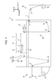
- Fig. 1 is a schematic cross-sectional view of the printer 1.
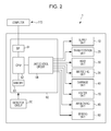
- Fig. 2 is a block diagram of the printer 1.
- arrows in Fig. 1 indicates the direction as a reference.
- a "forward-backward direction” indicates the direction perpendicular to the paper surface in Fig. 1 .
- roller sheet continuous sheet
- a pigmented ink is pigment particles forming a dyestuff that are dispersed inside a solvent.
- the pigmented ink has a tendency for the pigment particles to precipitate, if neglected for a long period of time.
- the printer 1 includes a transportation unit 20 as an example of a transportation part; a supply unit 10; a platen 29 as an example of a medium support part; a winding unit 90, along a transportation route on which the transportation unit 20 transports a roll sheet 2, and further includes a head unit 30 which performs printing in a printing region R on the transportation route; an ink feeding unit 35 which feeds the ink; a carriage unit 40 as an example of a head moving part; a heater unit 70 as an example of a heat supply part; an air blowing unit 80 which blows air to the roll sheet 2 on the platen 29; a controller 60 which controls the units or the like and administers an operation as the printer 1; and a detector group 50.
- the supply unit 10 supplies the roll sheet 2 to the transportation unit 20.
- the supply unit 10 includes a scroll 18 which supports the roll sheet 2 to be rotatably wound and a transition roller 19 which winds the roll sheet 2 drawn from the scroll 18 and guides the roll sheet to the transportation unit 20.
- the transportation unit 20 transports the roll sheet 2 supplied from the supply unit 10 along a predetermined transportation route.
- the transportation unit 20 includes a transition roller 21 which positions on the right in the horizontal direction with respect to the transition roller 19; a transition roller 22 which positions diagonally downward to the right when seen from the transition roller 21; a first transportation roller 23 which positions diagonally upward to the right (upstream side of the transportation direction when seen from the platen 29) when seen from the transition roller 22; a second transportation roller 24 which positions on the right (downstream side of the transportation direction when seen from the platen 29) when seen from the first transportation roller 23; an inversion roller 25 which positions vertically downward when seen from the second transportation roller 24; a transition roller 26 which positions on the right when seen from the inversion roller 25; and a delivery roller 27 which positions upward when seen from the transition roller 26.
- the transition roller 21 is a roller which winds from the left side and loosens downward the roll sheet 2 supplied from the transition roller 19.
- the transition roller 22 is a roller which winds from the left side and transports diagonally upward to the right the roll sheet 2 supplied from the transition roller 21.
- the first transportation roller 23 includes a first drive roller 23a which is driven by a motor (not illustrated) and a first driven roller 23b which is placed opposing the first drive roller 23a while pinching the roll sheet 2.
- the transportation roller 23 pulls up the roll sheet 2 which is loosened downward and transports the sheet to the printing region R which opposes the platen 29.
- the transportation roller 23 is set to temporarily stop the transportation while image printing is not performed with respect to the roll sheet 2 portion on the printing region R.
- the first driven roller 23b is rotated according to the rotation drive of the first drive roller 23a by the drive control of the controller 60.
- the transportation volume (length of the roll sheet portion) of the roll sheet 2 which is positioned on the platen 29 may be adjusted.
- the transportation unit 20, as described above, includes a mechanism which transports by loosening downward the roll sheet 2 portion wound across the transition rollers 21 and 22 and the first transportation roller 23.
- the loosening of the roll sheet 2 is monitored by the controller 60 based on a detection signal from a loosening detection sensor (not illustrated).
- a loosening detection sensor detects the roll sheet 2 portion which is loosened across the transition rollers 21 and 22 and the first transportation roller 23
- the transportation unit 20 may transport the roll sheet 2 in a loosening state since an appropriately large tension is applied to the portion.
- the transportation unit 20 temporarily stops the transportation of the roll sheet 2 since an excessively large tension is applied to the portion and the tension may be adjusted to an appropriate magnitude.
- the second transportation roller 24 includes a second drive roller 24a which is driven by a motor (not illustrated) and a second driven roller 24b which is placed opposing with respect to the second drive roller 24a while pinching the roll sheet 2.
- the transportation roller 24 transports the roll sheet 2 portion on which the image is recorded by the head unit 30, horizontally to the right along the supporting surface of the platen 29, and then transports vertically downward. As a result, the transportation direction of the roll sheet 2 is converted.
- the second driven roller 24b is rotated according to the rotation drive of the second drive roller 24a by the drive control of the controller 60. Thus, a predetermined tension applied with respect to the roll sheet 2 portion which positions on the platen 29 may be adjusted.
- the inversion roller 25 winds the roll sheet 2 supplied from the second transportation roller 24 from the left upper side and transports diagonally upward to the right.
- the transition roller 26 winds the roll sheet 2 supplied from the inversion roller 25 from the left lower side and transports upward.
- the delivery roller 27 winds the roll sheet 2 supplied from the transition roller 26 from the left lower side and delivers the sheet to a winding unit 90.
- the roll sheet 2 sequentially passes through each roller and thereby the transportation route is formed in order to transport the roll sheet 2.
- the roll sheet 2 is intermittently transported along the transportation route by the transportation unit 20 in region units corresponding to the printing region R.
- the head unit 30 ejects ink onto the roll sheet 2 portion which is sent into the printing region R (on the platen 29) by the transportation unit 20.
- the head unit 30 includes a head 31.
- the head 31, at the lower surface thereof, has rows of nozzles which line up in the row direction.
- the embodiment includes the row of nozzles respectively formed from a plurality of nozzles #1 to #N per color, white (W), cyan (C), magenta (M), yellow (Y), black (K) and the like.
- the respective nozzles #1 to #N in the rows of nozzles are arranged linearly in the crossing direction (row direction) which crosses the transportation direction of the roll sheet 2.
- the respective rows of the nozzles are placed in parallel apart from each other along the transportation direction.
- the respective nozzles #1 to #N have a piezoelectric element (not illustrated) as a drive element in order to eject ink droplets. If a voltage of a predetermined time width is applied to between electrodes provided at both of ends of the piezoelectric element, the piezoelectric element expands in response to the application time of the voltage and deforms a side wall of the flow channel of the ink. As a result, the volume of the flow channel of the ink contracts in response to the expansion of the piezoelectric element and the ink which corresponds to the contraction becomes ink droplets which are ejected from the respective nozzles #1 to #N of each color.
- the ink feeding unit 35 feeds the ink to the head unit 30 and is plurally provided per ink colors.
- the ink feeding unit 35 is connected to the head unit 30 (head 31) via an ink supply tube. For that reason, the head 31 ejects the ink supplied from the ink feeding unit 35 with respect to the roll sheet 2 portion which is positioned on the platen 29 and thereby image printing may be performed.
- the ink feeding unit 35 will be described in detail later.
- the carriage unit 40 moves the head unit 30 (head 31).
- the carriage unit 40 includes a guide rail 41 (illustrated by two-dot chain line in Fig. 1 ) which extends in the left-right direction, a carriage 42 which is supported so as to reciprocate in the left-right direction (moving direction) along the guide rail 41, and a motor (not illustrated).
- the carriage 42 includes four sub-carriages and a plurality of heads 31 is provided for each of the sub-carriages.
- the carriage 42 is configured so as to integrally move with the head 31 by the drive of the motor (not illustrated).
- the position (position in the left-right direction) of the carriage 42 (head 31 or each nozzle row) in the guide rail 41 may be obtained in such a manner that the controller 60 detects a rising edge and a falling edge in pulse signals output from an encoder which is provided at a motor (not illustrated) and counts the edges.
- the carriage 42 when cleaning the head 31 after image printing, the carriage 42, being integrated with the head 31, moves in the transportation direction (upstream side) when seen from the platen 29 at the upstream side in the transportation direction along the guide rail 41 and stops at a home position HP where the cleaning is performed (refer to Fig. 1 ).
- a cleaning unit (not illustrated) is provided at the home position HP.
- the cleaning unit includes a cap and a suction pump. If the carriage 42 positions at the home position HP, the cap (not illustrated) comes into contact with a lower surface (nozzle surface) of the head 31. If the suction pump (not illustrated) is operated in such an adhered state, the ink inside the head 31 is suctioned together with thickened ink or paper dust. Thus, a clogged nozzle is restored from the non-ejecting state and thereby the cleaning of the head is completed.
- the platen 29 supports the roll sheet 2 portion which positions in the printing region R on the transportation route and heats the portion. As illustrated in Fig. 1 , the platen 29 is provided corresponding to the printing region R on the transportation route and arranged at a region along the transportation route between the first transportation roller 23 and the second transportation roller 24. Thus, the platen 29 may heat the roll sheet 2 portion, receiving the supply of a heat generated by the heater unit 70.
- the heater unit 70 is intended to heat the roll sheet 2 and includes a heater (not illustrated).
- the heater has nichrome wires and is configured so that the nichrome wires are arranged to have a constant distance from a supporting surface of the platen 29. For that reason, the heater, being electrically connected and the nichrome wires themselves generating heat, may transmit the heat to the roll sheet 2 portion which positions on the supporting surface of the platen 29. Since the heater is configured so that the nichrome wires are built-in all over the platen 29, the heat may be uniformly transmitted with respect to the roll sheet 2 portion on the platen 29. In the embodiment, the roll sheet 2 portion is uniformly heated such that the temperature of the roll sheet 2 portion on the platen 29 becomes 45°C. As a result, the ink which impacts the roll sheet 2 portion may be dried.
- the air blowing unit 80 includes fans 81 as an example of a blower and a motor (not illustrated) which rotates the fans 81.
- the fans 81 by rotating, send air to the roll sheet 2 on the platen 29 and dry the ink which impacts the roll sheet 2.
- a plurality of the fans 81 are provided in a cover (not illustrated) which is provided at the main body and capable of opening and closing. Then, each of the fans 81 positions upward from the platen 29 when the cover is closed and opposes the supporting surface (roll sheet 2 on the platen 29) of the platen 29.
- the winding unit 90 winds the roll sheet 2 (roll sheet which finishes image printing) supplied by the transportation unit 20.
- the winding unit 90 includes a transition roller 91 which transports the roll sheet 2 supplied from the delivery roller 27 from the left upper side diagonally downward to the right and a winding drive shaft 92 which is rotatably supported and winds the roll sheet 2 supplied from the transition roller 91.
- the controller 60 is a control unit for controlling the printer 1. As illustrated in Fig. 2 , the controller 60 includes an interface unit 61, a CPU 62, a memory 63 and a unit control circuit 64.
- the interface unit 61 sends and receives data between a host computer 110 which is an external device and the printer 1.
- the CPU 62 is an arithmetic processing unit to control the entire printer 1.
- the memory 63 secures a region of the CPU 62 which stores programs, working space or the like. The CPU 62 controls each unit using the unit control circuit 64 according to the programs stored in the memory 63.
- the detector group 50 monitors situations inside the printer 1 and, for example, includes a rotary-type encoder which is attached to the transportation roller and used in controlling the transportation of the medium or the like, a sheet detecting sensor which detects whether the transported medium is present or absent, and a linear-type encoder which detects the position of the carriage 42 (or head 31) in the moving direction (left-right direction).
- a rotary-type encoder which is attached to the transportation roller and used in controlling the transportation of the medium or the like
- a sheet detecting sensor which detects whether the transported medium is present or absent
- a linear-type encoder which detects the position of the carriage 42 (or head 31) in the moving direction (left-right direction).
- Fig. 3 is a view illustrating the configuration example of the ink feeding unit 35.
- the ink feeding unit 35 supplies an ink to a head unit 30 and is plurally provided per each color. That is, each ink feeding unit 35 feeds the ink of different color to a corresponding head 31.
- each ink feeding unit 35 which supplies white ink (W) is exemplified for description.
- the white ink is water-based ink for which white titanium oxide (titanium oxide) is used as a pigment and is used for printing background color (white color) of a color image when printing on a transparent medium.
- the ink feeding unit 35 includes an ink cartridge IC, a sub ink tank ST as an example of a first liquid accommodation unit, a spare ink tank SST as an example of a second liquid accommodation unit, a first ink supply tube 34 which supplies the ink flowed out of the ink cartridge IC to the sub ink tank ST or the spare ink tank SST, a second ink supply tube 36 as an example of a first flow channel which allows the sub ink tank ST to communicate with the head unit 30, a third ink supply tube 37 as an example of a second flow channel which allows the second ink supply tube 36 to communicate with the spare ink tank SST, and a supply pump P as an example of a liquid supply unit.
- the ink cartridge IC accommodates the ink for supplying to the head unit 30.
- the ink cartridge IC includes an outlet port ICo where the first ink supply tube 34 is connected and which is provided at the lower side portion in the vertical direction. Then, the ink cartridge IC is configured to be detachably attached to the printer main body.
- the sub ink tank ST temporarily accommodates the ink which is supplied to the head unit 30 from the ink cartridge IC.
- the sub ink tank ST includes an inlet port STi where the first ink supply tube 34 is connected and which is provided at the upper side portion, and a plurality of openings STo where a plurality of the second ink supply tubes 36 is respectively connected and which is provided at the lower side portion.
- the sub ink tank ST is fixed inside the printer. That is, the sub ink tank ST is configured not to be detachably attached to the printer main body unlike the ink cartridge IC.
- the ink accommodated in the sub ink tank ST is neglected for a long period of time, the ink is apt to precipitate. As illustrated in Fig. 3 , such precipitation may cause a density difference between the upper side and the lower side in the vertical direction inside the sub ink tank ST. Particularly, if the ink is a pigmented ink such as white ink, the density due to the precipitation markedly occurs. Then, if the ink after precipitation is used for printing an image, as time goes by, the image is gradually changed to have a different density compared to the initial image and accordingly the printed image quality may be degraded.
- the ink since the ink reciprocates between the sub ink tank ST and the spare ink tank SST, the precipitated ink inside the sub ink tank ST is stirred and thereby the uniformity of the density of the ink is improved. The details will be described later.
- the ink accommodated in the sub ink tank ST precipitates, the ink accommodated in the ink cartridge IC may well precipitate.
- the ink cartridge IC is detachably attached to the printer main body, a user may detach the ink cartridge IC from the main body, shaking up and down, and thereby may eliminate the precipitation of the ink.
- the spare ink tank SST temporarily accommodates the ink delivered from the sub ink tank ST in order to return the ink to sub ink tank ST.
- the spare ink tank SST includes an inlet port SSTi where the first ink supply tube 34 is connected and which is provided at the upper side portion in the vertical direction, and a plurality of openings SSTo where a plurality of the third ink supply tubes 37 are respectively connected and which is provided at the lower side portion in the vertical direction.
- the ink accommodated in the sub ink tank ST precipitates after the passage of an extended period of time, density difference occurs between the upper side and the lower side in the vertical direction inside the sub ink tank ST as illustrated in Fig. 3 .
- the ink accommodated in the sub ink tank ST is sequentially delivered to the spare ink tank SST by the supply pump P.
- the spare ink tank SST may temporarily accommodate the ink delivered from the sub ink tank ST by successively admitting the ink from the opening SSTo. Then, if the movement of the ink accommodated in the sub ink tank ST is all completed, the ink accommodated in the spare ink tank SST is returned to the sub ink tank ST again by the supply pump P before precipitation.
- the ink is stirred by reciprocating between the sub ink tank ST and the spare ink tank SST and thereby uniformity of the density of the ink may be improved.
- the first ink supply tube 34 is a flow channel formed so as to supply the ink from the ink cartridge IC to the sub ink tank ST or the spare ink tank SST and includes a supply pump PO and a valve 34V on the flow channel.
- a first ink supply tube 341 which connects the outlet port ICo of the ink cartridge IC to the inlet port STi of the sub ink tank ST
- a first ink supply tube 342 which connects the outlet port ICo of the ink cartridge IC to the inlet port SSTi of the spare ink tank SST.
- the valve 34V is an on-off valve in order to open or close the flow channel of the first ink supply tube 34 and performs an opening-closing operation in response to the control signal from the controller 60 when replacing the ink cartridge IC or when supplying the ink to the sub ink tank ST or the spare ink tank SST.
- a valve 341V is provided on the flow channel of the first ink supply tube 341 and a valve 342V is provided on the flow channel of the first ink supply tube 342.
- valves 341V and 342V are check valves and thereby the ink may not flow back from the sub ink tank ST or the spare ink tank SST to the ink cartridge IC.
- the supply pump P0 supplies compressed air in response to the control signal from the controller 60, suctioning the ink inside the ink cartridge IC, and thereby sends the ink into the sub ink tank ST or the spare ink tank SST.
- the second ink supply tube 36 is a flow channel formed so as to supply the ink from the sub ink tank ST to the head unit 30. Then, a valve 36Vu of the upstream side and a valve 36Vd of the downstream side are provided on the flow channel.
- each tube allows the sub ink tank ST to respectively communicate with the head unit 30.
- a carriage 42 according to the embodiment includes four sub-carriages, each sub-carriage having a plurality of the heads 31 and allowing each of the sub-carriages to correspond to the ink supply tube, and supplies white ink to the respective heads 31.
- valves 36Vu and 36Vd are on-off valves in order to open or close the flow channel of the second ink supply tube 36 and performs an opening-closing operation in response to the control signal from the controller 60 when allowing the ink to move between the sub ink tank ST and the spare ink tank SST.
- a third ink supply tube 37 is a flow channel formed so as to allow the spare ink tank SST to communicate with the first ink supply tube 36. Then, a valve 37V and the supply pump P as an example of the liquid supply unit are provided on the flow channel.
- each tube is connected to each of the second ink supply tubes 361 to 364. Accordingly, the sub ink tank ST and the spare ink tank SST may be communicated with each other.
- the valve 37V is the on-off valve in order to open or close the flow channel of the third ink supply tube 37 and performs an opening-closing operation in response to the control signal from the controller 60 when allowing the ink to move between the sub ink tank ST and the spare ink tank SST.
- valves 371V to 374V respectively corresponding to a plurality of the third ink supply tubes 371 to 374.
- the supply pump P supplies compressed air and thereby allows the ink to flow between the sub ink tank ST and the spare ink tank SST. That is, the supply pump P supplies the compressed air in response to the control signal from the controller 60, suctioning the ink inside the sub ink tank ST, delivering the ink into the spare ink tank SST, and suctioning the ink inside the spare ink tank SST, and thereby may return the ink to the sub ink tank ST.
- a supply pump P1 which suctions the ink inside the sub ink tank ST and delivers the ink into the spare ink tank SST
- a supply pump P2 which suctions the ink inside the spare ink tank SST and returns the ink to the sub ink tank ST.
- the supply pump P1 is provided on the flow channel formed by connecting the second ink supply tube 361 to the third ink supply tube 371 and on the flow channel formed by connecting the second ink supply tube 364 to the third ink supply tube 374.
- the supply pump P2 is provided on the flow channel formed by connecting the second ink supply tube 362 to the third ink supply tube 372 and on the flow channel formed by connecting the second ink supply tube 363 to the third ink supply tube 373. That is, the flow channel formed by connecting the second ink supply tube 361 to the third ink supply tube 371 and the flow channel formed by connecting the second ink supply tube 364 to the third ink supply tube 374 may form a dedicated delivery flow channel for delivering the ink from the sub ink tank ST to the spare ink tank SST.
- the flow channel formed by connecting the second ink supply tube 362 to the third ink supply tube 372 and the flow channel formed by connecting the second ink supply tube 363 to the third ink supply tube 373 may form a dedicated returning flow channel for returning the ink from the spare ink tank SST to the sub ink tank ST.
- a controller 60 Various operations of the printer 1 are realized mainly by a controller 60.
- a CPU 62 processes a program stored in a memory 63.
- the program is configured by a code for performing various operations which is to be described below.
- a sensor (not illustrated) detects whether residual quantity of the ink is small inside the sub ink tank ST.
- a controller 60 performs a control for feeding the ink inside the ink cartridge IC to the sub ink tank ST, based on a detection signal from the sensor.
- the controller 60 controls opening and closing operations of each valve, closing valves 342V, 36Vu and 37V, and opens a valve 341V.
- the controller 60 controls opening and closing operations of each valve, closing valves 342V, 36Vu and 37V, and opens a valve 341V.
- flow channels of a first ink supply tube 342, a plurality of second ink supply tubes 36 and a plurality of third ink supply tubes 37 are closed, and the flow channel of a first ink supply tube 341 is open.
- the controller 60 drives a supply pump P0 to suction the ink inside the ink cartridge IC and to deliver the ink to the sub ink tank ST.
- the ink flowed out of the ink cartridge IC flows through the first ink supply tube 341 to be accommodated in the sub ink tank ST.
- the ink in order to improve the uniformity of the density of the ink accommodated in the sub ink tank ST, the ink is made to reciprocate between the sub ink tank ST and a spare ink tank SST and thereby the precipitated ink is stirred.
- the agitating operation will be described.
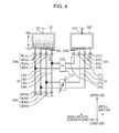
- Fig. 4 illustrates a state where a delivery of the ink is started from the sub ink tank ST to the spare ink tank SST.
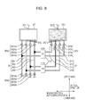
- Fig. 5 illustrates a state where a return of the ink is started from the spare ink tank SST to the sub ink tank ST.
- Fig. 6 illustrates a state of the sub ink tank ST after being stirred.
- the controller 60 controls opening and closing operations of each valve, closing valves 341V, 342V, 361Vd to 364Vd, and opens valves 361Vu to 364Vu and 371V to 374V.
- flow channels on the downstream side from the sub ink tank ST to the head unit 30 among the first ink supply tubes 341 and 342 and the second ink supply tubes 361 to 364 are closed.
- Flow channels on the upstream side from the sub ink tank ST to the spare ink tank SST among the second ink supply tubes 361 to 364 and flow channels of the third ink supply tubes 371 to 374 are open.
- the controller 60 drives only the supply pump P1 to sequentially deliver the ink inside the sub ink tank ST toward the spare ink tank SST.
- the ink flowed out of openings STo of both left and right ends flows to the respective third ink supply tubes 371 and 374 via the second ink supply tubes 361 and 364, and is successively accommodated in the spare ink tank SST.
- a sensor (not illustrated) detects whether all of the ink inside the sub ink tank ST removed. At this time, as illustrated in Fig. 5 , the ink delivered from the sub ink tank ST, being slightly mixed, is accommodated in the spare ink tank SST.
- the controller 60 stops the drive of the supply pump P1 and starts the drive of the supply pump P2 in order to immediately return the ink inside the spare ink tank SST to sub ink tank ST, based on the detection signal from the sensor (not illustrated).
- the controller 60 continuously drives only the supply pump P2 to suction the ink inside the spare ink tank SST and sequentially return the ink toward the sub ink tank ST.
- the ink flowed out of a central opening SSTo flows to the respective second ink supply tubes 362 and 363 via the respective third ink supply tubes 372 and 373 and is successively accommodated in the sub ink tank ST.
- the controller 60 drives the supply pump P2 until the ink inside the spare ink tank SST is removed (until detected by a sensor, not illustrated detects).
- the controller 60 driving the supply pumps P1 and P2, controls to adjust pressure difference between inside the sub ink tank St and inside the spare ink tank SST, the ink reciprocates between the sub ink tank ST and the spare ink tank SST. Then, such a reciprocating movement stirs the precipitated ink inside the sub ink tank ST and thereby the uniformity of the density of the ink may be improved.
- the controller 60 controls opening and closing operations of each valve, closing valves 371V to 374V, and opens valves 361Vu to 364Vu and 361Vd to 364Vd.
- the ink after being agitated flows out of the respective openings STo of the sub ink tank ST, flowing to the respective second ink supply tubes 36, and is supplied to the head unit 30 (head 31).
- the operation example where the reciprocating movement between the sub ink tank ST and the spare ink tank SST is performed only once is described as above.
- the reciprocating movement may be performed twice or more. The more reciprocating movement is repeated, the more the uniformity of the density of the ink is improved.
- the printer 1 includes the head unit 30 which ejects the ink to the roll sheet 2; the sub ink tank ST which accommodates the ink; the spare ink tank SST which is different from the sub ink tank ST; the second ink supply tube 36 which allows the sub ink tank ST to communicate with the head unit 30; the third ink supply tube 37 which allows the second ink supply tube 36 to communicate with the spare ink tank SST; and the supply pump P which delivers the ink from the sub ink tank ST to the spare ink tank SST via the second ink supply tube 36 and the third ink supply tube 37, and returns the ink from the spare ink tank SST to the sub ink tank ST via the third ink supply tube 37 and the second ink supply tube 36.
- the precipitated ink is mixed to improve the uniformity of the density of the ink. For that reason, even if precipitation of the ink occurs due to long term neglecting of the ink, an image which has uniform density may be printed and thereby printed image quality may be stably improved.
- the ink cartridge IC is detachably attached to the printer main body, a user may detach the ink cartridge IC from the main body and shake the ink cartridge IC up and down to solve the precipitation of the ink.
- the invention according to the present embodiment is effective in a case where the precipitation of the ink occurs in the sub ink tank ST.
- Fig. 7 is an explanatory view of a first comparative example.
- An ink feeding unit 35 according to the comparative example allows a sub ink tank ST to communicate with a spare ink tank SST using only a third ink supply tube 37 and a valve 37V and a supply pump P are provided on a flow channel of the third ink supply tube 37.
- a controller 60 closes valves 361Vu to 364Vu, opens a valve 37V and drives the supply pump P to suction an ink inside a sub ink tank ST, to deliver the ink to a spare ink tank SST, to suction the ink inside the spare ink tank SST and to sequentially return the ink toward the sub ink tank ST.
- the precipitated ink is mixed and thereby the uniformity of the density of the ink may be improved.
- the ink which is present between the sub ink tank ST and the valve 361Vu among the inks which are present inside the second ink supply tube 361 does not reciprocate between the sub ink tank ST and the spare ink tank SST and has a tendency to remain at the position.
- the printer 1 includes a valve 36Vu which is provided on the second ink supply tube 36 and opens or closes the flowing out of the ink accommodated in the sub ink tank ST, and the second ink supply tube 36 is set to be connected to the third ink supply tube 37 at a position of a head unit 30 side than the position of the valve 36Vu.
- the embodiment allows that the ink which is present between the sub ink tank ST and the valve 361Vu among the inks which are present inside the second ink supply tube 361 reaches the spare ink tank SST via the third ink supply tube 371.
- the remaining ink may reciprocate between the sub ink tank ST and the spare ink tank SST due to a agitating operation thereafter.
- all the precipitated ink may be mixed to improve uniformity of the density of the ink.
- Fig. 8 is an explanatory view of a second comparative example.
- An ink feeding unit 35 according to the comparative example unlike the embodiment, simultaneously drives supply pumps P1 and P2 when ink is allowed to reciprocate between a sub ink tank ST and a spare ink tank SST.
- the pumps delivers the ink using all of four second ink supply tubes 36 and third ink supply tubes 37, and returns the ink using all of the four third ink supply tubes 37 and the second ink supply tubes 36.
- the precipitated ink may be mixed to improve the uniformity of the density of the ink.
- the ink flows through second ink supply tubes 361 to 364, flows through third ink supply tubes 371 to 374 and reaches the spare ink tank SST.
- some ink may not reach the spare ink tank SST and may remain inside the second ink supply tubes 361 to 364 and the third ink supply tubes 371 to 374.
- the supply pumps P1 and P2 are operated to return the ink inside the spare ink tank SST to the sub ink tank ST, the remaining ink may not be mixed inside the spare ink tank SST and may return to the sub ink tank ST without change.
- a plurality of second ink supply tubes 36 and third ink supply tubes 37 are respectively provided.
- second ink supply tubes 361 and 364 and third ink supply tubes 371 and 374 are provided through which a liquid flows only when delivering the liquid
- second ink supply tubes 362 and 363 and third ink supply tubes 372 and 373 are provided through which the liquid flows only when returning the liquid.
- the supply pump P delivers the liquid from the sub ink tank ST to the spare ink tank SST via the second ink supply tubes 361 and 364 and the third ink supply tubes 371 and 374, and returns the liquid from the spare ink tank SST to the sub ink tank ST via the second ink supply tubes 362 and 363 and the third ink supply tubes 372 and 373.
- the embodiment may use four second ink supply tubes 36 and four third ink supply tubes 37 by dividing the tubes into two tubes each. Accordingly, a dedicated delivery flow channel for delivering the ink from the sub ink tank ST to the spare ink tank SST and a dedicated returning flow channel for returning the ink from the spare ink tank SST to the sub ink tank ST may be formed.
- the remaining ink may reach the spare ink tank SST due to the agitating operation thereafter.
- the remaining ink may reciprocate between the sub ink tank ST and the spare ink tank SST.
- all the precipitated ink may be mixed and the uniformity of the density of the ink may be more improved.
- the embodiment mainly describes a liquid ejecting apparatus, but includes a disclosure of a liquid transfer method or the like.
- the embodiment is to facilitate understanding of the invention and is not construed as limiting the invention.
- the invention may be modified and improved without departing from the spirit. It is obvious that the invention includes equivalents thereof. In particular, even the embodiment described below may be included in the invention.
- an ink jet type printer is exemplified as a liquid ejecting apparatus, but not limited thereto.
- a liquid ejecting apparatus which ejects another liquid besides ink may also be exemplified.
- Various liquid ejecting apparatuses which include a liquid ejecting head to eject a micro-droplet may be adaptable.
- the droplet means a state of the liquid which is ejected from the liquid ejecting apparatus and includes being granular, tear-like and pulled into a thread-like tail.
- the so-called liquid may be a material which the liquid ejecting apparatus may eject.
- a substance may be acceptable if the substance is in a state of liquid phase.
- Liquid-like bodies with high or low viscosity sol, gel water, other inorganic solvents, organic solvents, solutions, liquid resins and liquid metals (metallic melt) may be included.
- anything in which particles of functional material formed from solids such as pigments or metal particles are dissolved, dispersed or mixed in a solvent may be included.
- an ink as described in the embodiment, a liquid crystal or the like may be mentioned as a typical example of the liquid.
- the ink includes various liquid compositions such as a general water-based ink, oil-based ink, gel ink, hot melt ink or the like.
- the liquid ejecting apparatus for example, there may be a liquid ejecting apparatus that ejects liquid containing, in the form of dispersed or dissolved material, electrode materials or coloring materials or the like used in manufacturing a liquid crystal display, an EL (electroluminescence) display, a plane emission display, a color filter or the like; a liquid ejecting apparatus that ejects liquid which becomes a sample by being used as a precision pipette; printing equipment; a micro-dispenser or the like.
- a liquid ejecting apparatus that ejects liquid containing, in the form of dispersed or dissolved material, electrode materials or coloring materials or the like used in manufacturing a liquid crystal display, an EL (electroluminescence) display, a plane emission display, a color filter or the like
- a liquid ejecting apparatus that ejects liquid which becomes a sample by being used as a precision pipette
- printing equipment a micro-dispenser or the like.
- a liquid ejecting apparatus that ejects a pinpoint of lubricant to precision machinery such as timepieces or cameras; a liquid ejecting apparatus that ejects transparent resin liquid of ultraviolet curable resin onto a substrate in order to form a fine semi-spherical lens (optical lens) which is used in optical communication element or the like; and a liquid ejecting apparatus that ejects an etching liquid such as acid, alkali or the like in order to etch the substrate or the like may be employed.
- the invention may be adaptable to any one of the above apparatuses.
- the agitating operation may be started before starting the printing operation after power-up.
- the agitating operation may be started every time when a predetermined time elapses.
- a computer 60 obtains timekeeping information (power-off period) from the timer, reads out predetermined period information (for example, two months) from a memory 63 and compares the information. Then, the computer 60 determines whether the power-off period is equivalent to or more than a predetermined period (two months) and if equivalent to or more than the predetermined period, performs a process for the agitating operation.
- timekeeping information power-off period
- predetermined period information for example, two months
- 1 liquid ejecting apparatus 2 roll sheet, 10 supply unit, 18 scroll, 19 transition roller, 20 transportation unit, 21 transition roller, 22 transition roller, 23 first transportation roller, 24 second transportation roller, 25 inversion roller, 26 transition roller, 27 delivery roller, 29 platen, 30 head unit, 31 head, 34 first ink supply tube, 34V valve, 35 ink feeding unit, 36 second ink supply tube, 36V valve, 37 third ink supply tube, 37V valve, 40 carriage unit, 41 guide rail, 42 carriage, 50 detector group, 60 controller, 70 heater unit, 80 air blowing unit, 81 fans, 90 winding unit, 91 transition roller, 92 winding drive shaft, 110 host computer, IC ink cartridge, ST sub ink tank, SST spare ink tank, P supply pump.
Landscapes
- Ink Jet (AREA)
Abstract
Description
- The present disclosure relates to a liquid ejecting apparatus and a liquid transfer method.
- As an example of a liquid ejecting apparatus, an ink jet printer which ejects a liquid such as an ink on various mediums such as papers or films and performs an image printing has been known. The ink jet printer includes an accommodation unit which accommodates the liquid and a head unit which ejects the liquid on the mediums. Then, if the liquid amount inside the head unit decreases due to the liquid ejection, the liquid is fed from the accommodation unit (for example, Patent Literature 1).
- Patent Literature 1: Japanese Unexamined Patent Application Publication No.
2005-246908 - If the ink jet printer is unused for a long period of time, there are cases where the liquid which is accommodated in the accommodation unit precipitates. Then, if the liquid precipitates, a density difference occurs between the upper side and the lower side in the accommodation unit. As a result, if printing an image using such a liquid after precipitation, the image quality thereof may be unstable.
- The present invention is made under such circumstances and is aimed to make the density of a liquid which is ejected by a head unit uniformed as much as possible and to improve stability in a print image quality.
- According to a principal aspect of the invention, there is provided a liquid ejecting apparatus which is characterized by including a head unit that ejects a liquid onto a medium, a first liquid accommodation unit that accommodates the liquid, a second liquid accommodation unit that is different from the first liquid accommodation unit, a first flow channel that communicates with the first liquid accommodation unit and the head unit, a second flow channel that communicates with the first flow channel and the second liquid accommodation unit, and a liquid supply unit that delivers the liquid from the first liquid accommodation unit to the second liquid accommodation unit through the first flow channel and the second flow channel and that returns the liquid from the second liquid accommodation unit to the first liquid accommodation unit through the second flow channel and the first flow channel.
- The other aspects of the invention will be made clear, based on the description and the accompanying drawings.
-
- [
Fig. 1] Fig. 1 is a perspective view illustrating a configuration of aprinter 1. - [
Fig. 2] Fig. 2 is a block diagram illustrating a configuration of theprinter 1. - [
Fig. 3] Fig. 3 is an explanatory view of a configuration example of anink feeding unit 35. - [
Fig. 4] Fig. 4 is an explanatory view of an example operation for agitating inks, illustrating a state where a sub-ink tank ST starts to deliver inks to a spare ink tank SST. - [
Fig. 5] Fig. 5 is an explanatory view of an example operation for agitating inks, illustrating a state where a sub-ink tank ST starts to send inks back to a spare ink tank SST. - [
Fig. 6] Fig. 6 is an explanatory view of an example operation for agitating inks, illustrating a state of a sub-ink tank ST after being stirred. - [
Fig. 7] Fig. 7 is an explanatory view of a first comparative example. - [
Fig. 8] Fig. 8 is an explanatory view of a second comparative example. - The description and the accompanying drawings will disclose at least the following aspects.
- That is, there is provided a liquid ejecting apparatus which is characterized by including a head unit that ejects a liquid onto a medium, a first liquid accommodation unit that accommodates the liquid, a second liquid accommodation unit that is different from the first liquid accommodation unit, a first flow channel that communicates with the first liquid accommodation unit and the head unit, a second flow channel that communicates with the first flow channel and the second liquid accommodation unit, and a liquid supply unit that delivers the liquid from the first liquid accommodation unit to the second liquid accommodation unit through the first flow channel and the second flow channel and that returns the liquid from the second liquid accommodation unit to the first liquid accommodation unit through the second flow channel and the first flow channel.
- According to the liquid ejecting apparatus, density of the liquid which is ejected by the head unit is made to be as uniform as possible so as to improve the stability of printed image quality.
- In addition, the liquid ejecting apparatus may further include an on-off valve that opens or closes an outflow of the liquid which is accommodated in the first liquid accommodation unit, being provided on the first flow channel.
- The first flow channel may be connected to the second flow channel at a position further to the head unit side than a position of the on-off valve.
- According to the liquid ejecting apparatus, the density of the liquid may be further improved.
- In addition, in the liquid ejecting apparatus, the first flow channel and the second flow channel may be plurally provided respectively. A plurality of the first flow channels and the second flow channels may include a first dedicated delivery flow channel and a second dedicated delivery flow channel where the liquid flows only during a delivery between the delivery and a return of the liquid; and a first dedicated return flow channel and a second dedicated return flow channel where the liquid flows only during the return. The liquid supply unit may deliver the liquid from the first liquid accommodation unit to the second liquid accommodation unit through the first dedicated delivery flow channel and the second dedicated delivery flow channel, and may also return the liquid from the second liquid accommodation unit to the first liquid accommodation unit through the first dedicated return flow channel and the second dedicated return flow channel.
- According to the liquid ejecting apparatus, the density of the liquid may be further improved.
- In addition, there is provided a liquid transfer method preparing for a liquid ejecting apparatus that includes a head unit which ejects a liquid onto a medium; a first liquid accommodation unit which accommodates the liquid; a second liquid accommodation unit which is different from the first liquid accommodation unit; a first flow channel which communicates with the first liquid accommodation unit and the head unit; a second flow channel which communicates with the first flow channel and the second liquid accommodation unit; and a liquid supply unit.
- The liquid supply unit that delivers the liquid from the first liquid accommodation unit to the second liquid accommodation unit through the first flow channel and the second flow channel and that returns the liquid from the second liquid accommodation unit to the first liquid accommodation unit through the second flow channel and the first flow channel.
- According to the liquid transfer method, the density of the liquid which is ejected by the head unit may be as uniform as possible and consequently stability in printed image quality may be improved.
- In the embodiments below, an inkjet printer 1 (hereinafter referred to as a "
printer 1") will be exemplified as a liquid ejecting apparatus for description. - A configuration example of a
printer 1 will be described with reference toFigs. 1 and2 .Fig. 1 is a schematic cross-sectional view of theprinter 1.Fig. 2 is a block diagram of theprinter 1. - In the following description, when referring to as an "upward-downward direction" and a "left-right direction", arrows in
Fig. 1 indicates the direction as a reference. In addition, a "forward-backward direction" indicates the direction perpendicular to the paper surface inFig. 1 . - In addition, the present embodiment will be described using a sheet or a film (hereinafter referred to as a "roll sheet (continuous sheet)") which is wound up in roll state as a medium on which the
printer 1 records an image. - Furthermore, the embodiment will be described using an ink (for example, pigmented ink) as an example of a liquid which is used in order for the
printer 1 to record the image on the roll sheet. A pigmented ink is pigment particles forming a dyestuff that are dispersed inside a solvent. The pigmented ink has a tendency for the pigment particles to precipitate, if neglected for a long period of time. - As illustrated in
Figs. 1 and2 , theprinter 1 according to the embodiment includes atransportation unit 20 as an example of a transportation part; asupply unit 10; aplaten 29 as an example of a medium support part; awinding unit 90, along a transportation route on which thetransportation unit 20 transports aroll sheet 2, and further includes ahead unit 30 which performs printing in a printing region R on the transportation route; anink feeding unit 35 which feeds the ink; acarriage unit 40 as an example of a head moving part; aheater unit 70 as an example of a heat supply part; an air blowingunit 80 which blows air to theroll sheet 2 on theplaten 29; acontroller 60 which controls the units or the like and administers an operation as theprinter 1; and adetector group 50. - The
supply unit 10 supplies theroll sheet 2 to thetransportation unit 20. Thesupply unit 10 includes ascroll 18 which supports theroll sheet 2 to be rotatably wound and atransition roller 19 which winds theroll sheet 2 drawn from thescroll 18 and guides the roll sheet to thetransportation unit 20. - The
transportation unit 20 transports theroll sheet 2 supplied from thesupply unit 10 along a predetermined transportation route. As illustrated inFig. 1 , thetransportation unit 20 includes atransition roller 21 which positions on the right in the horizontal direction with respect to thetransition roller 19; atransition roller 22 which positions diagonally downward to the right when seen from thetransition roller 21; afirst transportation roller 23 which positions diagonally upward to the right (upstream side of the transportation direction when seen from the platen 29) when seen from thetransition roller 22; asecond transportation roller 24 which positions on the right (downstream side of the transportation direction when seen from the platen 29) when seen from thefirst transportation roller 23; aninversion roller 25 which positions vertically downward when seen from thesecond transportation roller 24; atransition roller 26 which positions on the right when seen from theinversion roller 25; and adelivery roller 27 which positions upward when seen from thetransition roller 26. - The
transition roller 21 is a roller which winds from the left side and loosens downward theroll sheet 2 supplied from thetransition roller 19. - The
transition roller 22 is a roller which winds from the left side and transports diagonally upward to the right theroll sheet 2 supplied from thetransition roller 21. - The
first transportation roller 23 includes afirst drive roller 23a which is driven by a motor (not illustrated) and a first drivenroller 23b which is placed opposing thefirst drive roller 23a while pinching theroll sheet 2. Thetransportation roller 23 pulls up theroll sheet 2 which is loosened downward and transports the sheet to the printing region R which opposes theplaten 29. Thetransportation roller 23 is set to temporarily stop the transportation while image printing is not performed with respect to theroll sheet 2 portion on the printing region R. Furthermore, the first drivenroller 23b is rotated according to the rotation drive of thefirst drive roller 23a by the drive control of thecontroller 60. Thus, the transportation volume (length of the roll sheet portion) of theroll sheet 2 which is positioned on theplaten 29 may be adjusted. - The
transportation unit 20, as described above, includes a mechanism which transports by loosening downward theroll sheet 2 portion wound across thetransition rollers first transportation roller 23. The loosening of theroll sheet 2 is monitored by thecontroller 60 based on a detection signal from a loosening detection sensor (not illustrated). In detail, if the loosening detection sensor detects theroll sheet 2 portion which is loosened across thetransition rollers first transportation roller 23, thetransportation unit 20 may transport theroll sheet 2 in a loosening state since an appropriately large tension is applied to the portion. In contrast, if the loosening detection sensor does not detect theroll sheet 2 portion which is loosened, thetransportation unit 20 temporarily stops the transportation of theroll sheet 2 since an excessively large tension is applied to the portion and the tension may be adjusted to an appropriate magnitude. - The
second transportation roller 24 includes a second drive roller 24a which is driven by a motor (not illustrated) and a second drivenroller 24b which is placed opposing with respect to the second drive roller 24a while pinching theroll sheet 2. Thetransportation roller 24 transports theroll sheet 2 portion on which the image is recorded by thehead unit 30, horizontally to the right along the supporting surface of theplaten 29, and then transports vertically downward. As a result, the transportation direction of theroll sheet 2 is converted. Furthermore, the second drivenroller 24b is rotated according to the rotation drive of the second drive roller 24a by the drive control of thecontroller 60. Thus, a predetermined tension applied with respect to theroll sheet 2 portion which positions on theplaten 29 may be adjusted. - The
inversion roller 25 winds theroll sheet 2 supplied from thesecond transportation roller 24 from the left upper side and transports diagonally upward to the right. - The
transition roller 26 winds theroll sheet 2 supplied from theinversion roller 25 from the left lower side and transports upward. - The
delivery roller 27 winds theroll sheet 2 supplied from thetransition roller 26 from the left lower side and delivers the sheet to a windingunit 90. - As described above, the
roll sheet 2 sequentially passes through each roller and thereby the transportation route is formed in order to transport theroll sheet 2. In addition, theroll sheet 2 is intermittently transported along the transportation route by thetransportation unit 20 in region units corresponding to the printing region R. - The
head unit 30 ejects ink onto theroll sheet 2 portion which is sent into the printing region R (on the platen 29) by thetransportation unit 20. Thehead unit 30 includes ahead 31. - The
head 31, at the lower surface thereof, has rows of nozzles which line up in the row direction. The embodiment includes the row of nozzles respectively formed from a plurality ofnozzles # 1 to #N per color, white (W), cyan (C), magenta (M), yellow (Y), black (K) and the like. Therespective nozzles # 1 to #N in the rows of nozzles are arranged linearly in the crossing direction (row direction) which crosses the transportation direction of theroll sheet 2. The respective rows of the nozzles are placed in parallel apart from each other along the transportation direction. - The
respective nozzles # 1 to #N have a piezoelectric element (not illustrated) as a drive element in order to eject ink droplets. If a voltage of a predetermined time width is applied to between electrodes provided at both of ends of the piezoelectric element, the piezoelectric element expands in response to the application time of the voltage and deforms a side wall of the flow channel of the ink. As a result, the volume of the flow channel of the ink contracts in response to the expansion of the piezoelectric element and the ink which corresponds to the contraction becomes ink droplets which are ejected from therespective nozzles # 1 to #N of each color. - When the ink amount inside the
head unit 30 is decreased due to the ejection of the ink by thehead 31, theink feeding unit 35 feeds the ink to thehead unit 30 and is plurally provided per ink colors. Theink feeding unit 35 is connected to the head unit 30 (head 31) via an ink supply tube. For that reason, thehead 31 ejects the ink supplied from theink feeding unit 35 with respect to theroll sheet 2 portion which is positioned on theplaten 29 and thereby image printing may be performed. Theink feeding unit 35 will be described in detail later. - The
carriage unit 40 moves the head unit 30 (head 31). Thecarriage unit 40 includes a guide rail 41 (illustrated by two-dot chain line inFig. 1 ) which extends in the left-right direction, acarriage 42 which is supported so as to reciprocate in the left-right direction (moving direction) along theguide rail 41, and a motor (not illustrated). In the embodiment, thecarriage 42 includes four sub-carriages and a plurality ofheads 31 is provided for each of the sub-carriages. - The
carriage 42 is configured so as to integrally move with thehead 31 by the drive of the motor (not illustrated). The position (position in the left-right direction) of the carriage 42 (head 31 or each nozzle row) in theguide rail 41 may be obtained in such a manner that thecontroller 60 detects a rising edge and a falling edge in pulse signals output from an encoder which is provided at a motor (not illustrated) and counts the edges. - Then, when cleaning the
head 31 after image printing, thecarriage 42, being integrated with thehead 31, moves in the transportation direction (upstream side) when seen from theplaten 29 at the upstream side in the transportation direction along theguide rail 41 and stops at a home position HP where the cleaning is performed (refer toFig. 1 ). - A cleaning unit (not illustrated) is provided at the home position HP. The cleaning unit includes a cap and a suction pump. If the
carriage 42 positions at the home position HP, the cap (not illustrated) comes into contact with a lower surface (nozzle surface) of thehead 31. If the suction pump (not illustrated) is operated in such an adhered state, the ink inside thehead 31 is suctioned together with thickened ink or paper dust. Thus, a clogged nozzle is restored from the non-ejecting state and thereby the cleaning of the head is completed. - The
platen 29 supports theroll sheet 2 portion which positions in the printing region R on the transportation route and heats the portion. As illustrated inFig. 1 , theplaten 29 is provided corresponding to the printing region R on the transportation route and arranged at a region along the transportation route between thefirst transportation roller 23 and thesecond transportation roller 24. Thus, theplaten 29 may heat theroll sheet 2 portion, receiving the supply of a heat generated by theheater unit 70. - The
heater unit 70 is intended to heat theroll sheet 2 and includes a heater (not illustrated). The heater has nichrome wires and is configured so that the nichrome wires are arranged to have a constant distance from a supporting surface of theplaten 29. For that reason, the heater, being electrically connected and the nichrome wires themselves generating heat, may transmit the heat to theroll sheet 2 portion which positions on the supporting surface of theplaten 29. Since the heater is configured so that the nichrome wires are built-in all over theplaten 29, the heat may be uniformly transmitted with respect to theroll sheet 2 portion on theplaten 29. In the embodiment, theroll sheet 2 portion is uniformly heated such that the temperature of theroll sheet 2 portion on theplaten 29 becomes 45°C. As a result, the ink which impacts theroll sheet 2 portion may be dried. - The
air blowing unit 80 includesfans 81 as an example of a blower and a motor (not illustrated) which rotates thefans 81. Thefans 81, by rotating, send air to theroll sheet 2 on theplaten 29 and dry the ink which impacts theroll sheet 2. As illustrated inFig. 1 , a plurality of thefans 81 are provided in a cover (not illustrated) which is provided at the main body and capable of opening and closing. Then, each of thefans 81 positions upward from theplaten 29 when the cover is closed and opposes the supporting surface (rollsheet 2 on the platen 29) of theplaten 29. - The winding
unit 90 winds the roll sheet 2 (roll sheet which finishes image printing) supplied by thetransportation unit 20. The windingunit 90 includes atransition roller 91 which transports theroll sheet 2 supplied from thedelivery roller 27 from the left upper side diagonally downward to the right and a windingdrive shaft 92 which is rotatably supported and winds theroll sheet 2 supplied from thetransition roller 91. - The
controller 60 is a control unit for controlling theprinter 1. As illustrated inFig. 2 , thecontroller 60 includes aninterface unit 61, aCPU 62, amemory 63 and aunit control circuit 64. Theinterface unit 61 sends and receives data between ahost computer 110 which is an external device and theprinter 1. TheCPU 62 is an arithmetic processing unit to control theentire printer 1. Thememory 63 secures a region of theCPU 62 which stores programs, working space or the like. TheCPU 62 controls each unit using theunit control circuit 64 according to the programs stored in thememory 63. - The
detector group 50 monitors situations inside theprinter 1 and, for example, includes a rotary-type encoder which is attached to the transportation roller and used in controlling the transportation of the medium or the like, a sheet detecting sensor which detects whether the transported medium is present or absent, and a linear-type encoder which detects the position of the carriage 42 (or head 31) in the moving direction (left-right direction). - Herein, a configuration example of an
ink feeding unit 35 will be described with reference toFig. 3. Fig. 3 is a view illustrating the configuration example of theink feeding unit 35. - The
ink feeding unit 35 supplies an ink to ahead unit 30 and is plurally provided per each color. That is, eachink feeding unit 35 feeds the ink of different color to a correspondinghead 31. In addition, herein, as eachink feeding unit 35 has the same configuration, theink feeding unit 35 which supplies white ink (W) is exemplified for description. The white ink is water-based ink for which white titanium oxide (titanium oxide) is used as a pigment and is used for printing background color (white color) of a color image when printing on a transparent medium. - The
ink feeding unit 35 includes an ink cartridge IC, a sub ink tank ST as an example of a first liquid accommodation unit, a spare ink tank SST as an example of a second liquid accommodation unit, a firstink supply tube 34 which supplies the ink flowed out of the ink cartridge IC to the sub ink tank ST or the spare ink tank SST, a secondink supply tube 36 as an example of a first flow channel which allows the sub ink tank ST to communicate with thehead unit 30, a thirdink supply tube 37 as an example of a second flow channel which allows the secondink supply tube 36 to communicate with the spare ink tank SST, and a supply pump P as an example of a liquid supply unit. - The ink cartridge IC accommodates the ink for supplying to the
head unit 30. As illustrated inFig. 3 , the ink cartridge IC includes an outlet port ICo where the firstink supply tube 34 is connected and which is provided at the lower side portion in the vertical direction. Then, the ink cartridge IC is configured to be detachably attached to the printer main body. - The sub ink tank ST temporarily accommodates the ink which is supplied to the
head unit 30 from the ink cartridge IC. - As illustrated in
Fig. 3 , the sub ink tank ST includes an inlet port STi where the firstink supply tube 34 is connected and which is provided at the upper side portion, and a plurality of openings STo where a plurality of the secondink supply tubes 36 is respectively connected and which is provided at the lower side portion. - The sub ink tank ST is fixed inside the printer. That is, the sub ink tank ST is configured not to be detachably attached to the printer main body unlike the ink cartridge IC.
- Here, if the ink accommodated in the sub ink tank ST is neglected for a long period of time, the ink is apt to precipitate. As illustrated in
Fig. 3 , such precipitation may cause a density difference between the upper side and the lower side in the vertical direction inside the sub ink tank ST. Particularly, if the ink is a pigmented ink such as white ink, the density due to the precipitation markedly occurs. Then, if the ink after precipitation is used for printing an image, as time goes by, the image is gradually changed to have a different density compared to the initial image and accordingly the printed image quality may be degraded. - In contrast, in the embodiment, since the ink reciprocates between the sub ink tank ST and the spare ink tank SST, the precipitated ink inside the sub ink tank ST is stirred and thereby the uniformity of the density of the ink is improved. The details will be described later.
- In addition, if the ink accommodated in the sub ink tank ST precipitates, the ink accommodated in the ink cartridge IC may well precipitate. However, since the ink cartridge IC is detachably attached to the printer main body, a user may detach the ink cartridge IC from the main body, shaking up and down, and thereby may eliminate the precipitation of the ink.
- The spare ink tank SST temporarily accommodates the ink delivered from the sub ink tank ST in order to return the ink to sub ink tank ST.
- As illustrated in
Fig. 3 , the spare ink tank SST includes an inlet port SSTi where the firstink supply tube 34 is connected and which is provided at the upper side portion in the vertical direction, and a plurality of openings SSTo where a plurality of the thirdink supply tubes 37 are respectively connected and which is provided at the lower side portion in the vertical direction. - Here, as described above, since the ink accommodated in the sub ink tank ST precipitates after the passage of an extended period of time, density difference occurs between the upper side and the lower side in the vertical direction inside the sub ink tank ST as illustrated in
Fig. 3 . In such a case, the ink accommodated in the sub ink tank ST is sequentially delivered to the spare ink tank SST by the supply pump P. The spare ink tank SST may temporarily accommodate the ink delivered from the sub ink tank ST by successively admitting the ink from the opening SSTo. Then, if the movement of the ink accommodated in the sub ink tank ST is all completed, the ink accommodated in the spare ink tank SST is returned to the sub ink tank ST again by the supply pump P before precipitation. - In this manner, the ink is stirred by reciprocating between the sub ink tank ST and the spare ink tank SST and thereby uniformity of the density of the ink may be improved.
- In addition, an operation example for agitating the ink will be described in detail later.
- The first
ink supply tube 34 is a flow channel formed so as to supply the ink from the ink cartridge IC to the sub ink tank ST or the spare ink tank SST and includes a supply pump PO and avalve 34V on the flow channel. - In the embodiment, as illustrated in
Fig. 3 , there are provided a firstink supply tube 341 which connects the outlet port ICo of the ink cartridge IC to the inlet port STi of the sub ink tank ST, and a firstink supply tube 342 which connects the outlet port ICo of the ink cartridge IC to the inlet port SSTi of the spare ink tank SST. - The
valve 34V is an on-off valve in order to open or close the flow channel of the firstink supply tube 34 and performs an opening-closing operation in response to the control signal from thecontroller 60 when replacing the ink cartridge IC or when supplying the ink to the sub ink tank ST or the spare ink tank SST. - In the embodiment, a
valve 341V is provided on the flow channel of the firstink supply tube 341 and a valve 342V is provided on the flow channel of the firstink supply tube 342. - In addition, the
valves 341V and 342V are check valves and thereby the ink may not flow back from the sub ink tank ST or the spare ink tank SST to the ink cartridge IC. - The supply pump P0 supplies compressed air in response to the control signal from the
controller 60, suctioning the ink inside the ink cartridge IC, and thereby sends the ink into the sub ink tank ST or the spare ink tank SST. - AS illustrated in
Fig. 3 , the secondink supply tube 36 is a flow channel formed so as to supply the ink from the sub ink tank ST to thehead unit 30. Then, a valve 36Vu of the upstream side and a valve 36Vd of the downstream side are provided on the flow channel. - In the embodiment, as illustrated in
Fig. 3 , four secondink supply tubes 361 to 364 are provided as the flow channel for supplying white ink and each tube allows the sub ink tank ST to respectively communicate with thehead unit 30. To provide the four secondink supply tubes 361 to 364 in this manner is because acarriage 42 according to the embodiment includes four sub-carriages, each sub-carriage having a plurality of theheads 31 and allowing each of the sub-carriages to correspond to the ink supply tube, and supplies white ink to the respective heads 31. - The valves 36Vu and 36Vd are on-off valves in order to open or close the flow channel of the second
ink supply tube 36 and performs an opening-closing operation in response to the control signal from thecontroller 60 when allowing the ink to move between the sub ink tank ST and the spare ink tank SST. - In the embodiment, as illustrated in
Fig. 3 , there are provided valves 361Vu to 364Vu of the upstream side and valves 361Vd to 364Vd of the downstream side respectively corresponding to a plurality of the secondink supply tubes 361 to 364. - As illustrated in
Fig. 3 , a thirdink supply tube 37 is a flow channel formed so as to allow the spare ink tank SST to communicate with the firstink supply tube 36. Then, avalve 37V and the supply pump P as an example of the liquid supply unit are provided on the flow channel. - In the embodiment, as illustrated in
Fig. 3 , four thirdink supply tubes 371 to 374 are provided as the flow channel for supplying white ink and each tube is connected to each of the secondink supply tubes 361 to 364. Accordingly, the sub ink tank ST and the spare ink tank SST may be communicated with each other. - The
valve 37V is the on-off valve in order to open or close the flow channel of the thirdink supply tube 37 and performs an opening-closing operation in response to the control signal from thecontroller 60 when allowing the ink to move between the sub ink tank ST and the spare ink tank SST. - In the embodiment, as illustrated in
Fig. 3 , there are providedvalves 371V to 374V respectively corresponding to a plurality of the thirdink supply tubes 371 to 374. - The supply pump P supplies compressed air and thereby allows the ink to flow between the sub ink tank ST and the spare ink tank SST. That is, the supply pump P supplies the compressed air in response to the control signal from the
controller 60, suctioning the ink inside the sub ink tank ST, delivering the ink into the spare ink tank SST, and suctioning the ink inside the spare ink tank SST, and thereby may return the ink to the sub ink tank ST. - In the embodiment, as illustrated in
Fig. 3 , there are provided a supply pump P1 which suctions the ink inside the sub ink tank ST and delivers the ink into the spare ink tank SST, and a supply pump P2 which suctions the ink inside the spare ink tank SST and returns the ink to the sub ink tank ST. The supply pump P1 is provided on the flow channel formed by connecting the secondink supply tube 361 to the thirdink supply tube 371 and on the flow channel formed by connecting the secondink supply tube 364 to the thirdink supply tube 374. The supply pump P2 is provided on the flow channel formed by connecting the secondink supply tube 362 to the thirdink supply tube 372 and on the flow channel formed by connecting the secondink supply tube 363 to the thirdink supply tube 373. That is, the flow channel formed by connecting the secondink supply tube 361 to the thirdink supply tube 371 and the flow channel formed by connecting the secondink supply tube 364 to the thirdink supply tube 374 may form a dedicated delivery flow channel for delivering the ink from the sub ink tank ST to the spare ink tank SST. In contrast, the flow channel formed by connecting the secondink supply tube 362 to the thirdink supply tube 372 and the flow channel formed by connecting the secondink supply tube 363 to the thirdink supply tube 373 may form a dedicated returning flow channel for returning the ink from the spare ink tank SST to the sub ink tank ST. - Next, an operation example related to ink feeding of a
printer 1 will be described. - Various operations of the
printer 1 are realized mainly by acontroller 60. In particular, in the embodiment, aCPU 62 processes a program stored in amemory 63. Then, the program is configured by a code for performing various operations which is to be described below. - First, an operation example for supplying an ink from an ink cartridge IC to a sub ink tank ST will be described.
- A sensor (not illustrated) detects whether residual quantity of the ink is small inside the sub ink tank ST. A
controller 60 performs a control for feeding the ink inside the ink cartridge IC to the sub ink tank ST, based on a detection signal from the sensor. - First, the
controller 60 controls opening and closing operations of each valve, closing valves 342V, 36Vu and 37V, and opens avalve 341V. As a result, flow channels of a firstink supply tube 342, a plurality of secondink supply tubes 36 and a plurality of thirdink supply tubes 37 are closed, and the flow channel of a firstink supply tube 341 is open. - Next, the
controller 60 drives a supply pump P0 to suction the ink inside the ink cartridge IC and to deliver the ink to the sub ink tank ST. As a result, the ink flowed out of the ink cartridge IC flows through the firstink supply tube 341 to be accommodated in the sub ink tank ST. - If the ink accommodated in the sub ink tank ST remains unused for a long period of time, precipitation of the ink occurs.
- In the embodiment, with respect to the precipitation, in order to improve the uniformity of the density of the ink accommodated in the sub ink tank ST, the ink is made to reciprocate between the sub ink tank ST and a spare ink tank SST and thereby the precipitated ink is stirred. Herein, the agitating operation will be described.
- Next, an operation example for agitating the precipitated ink inside the sub ink tank ST will be described with reference to
Figs. 3 to 6 .Fig. 4 illustrates a state where a delivery of the ink is started from the sub ink tank ST to the spare ink tank SST.Fig. 5 illustrates a state where a return of the ink is started from the spare ink tank SST to the sub ink tank ST.Fig. 6 illustrates a state of the sub ink tank ST after being stirred. - As illustrated in
Fig. 3 , thecontroller 60 controls opening and closing operations of each valve, closingvalves 341V, 342V, 361Vd to 364Vd, and opens valves 361Vu to 364Vu and 371V to 374V. As a result, flow channels on the downstream side from the sub ink tank ST to thehead unit 30 among the firstink supply tubes ink supply tubes 361 to 364 are closed. Flow channels on the upstream side from the sub ink tank ST to the spare ink tank SST among the secondink supply tubes 361 to 364 and flow channels of the thirdink supply tubes 371 to 374 are open. - Next, as illustrated in
Fig. 4 , thecontroller 60 drives only the supply pump P1 to sequentially deliver the ink inside the sub ink tank ST toward the spare ink tank SST. As a result, the ink flowed out of openings STo of both left and right ends flows to the respective thirdink supply tubes ink supply tubes - Then, a sensor (not illustrated) detects whether all of the ink inside the sub ink tank ST removed. At this time, as illustrated in
Fig. 5 , the ink delivered from the sub ink tank ST, being slightly mixed, is accommodated in the spare ink tank SST. - The
controller 60 stops the drive of the supply pump P1 and starts the drive of the supply pump P2 in order to immediately return the ink inside the spare ink tank SST to sub ink tank ST, based on the detection signal from the sensor (not illustrated). - As illustrated in
Fig. 5 , thecontroller 60 continuously drives only the supply pump P2 to suction the ink inside the spare ink tank SST and sequentially return the ink toward the sub ink tank ST. As a result, the ink flowed out of a central opening SSTo flows to the respective secondink supply tubes ink supply tubes controller 60 drives the supply pump P2 until the ink inside the spare ink tank SST is removed (until detected by a sensor, not illustrated detects). - In this manner, since the
controller 60, driving the supply pumps P1 and P2, controls to adjust pressure difference between inside the sub ink tank St and inside the spare ink tank SST, the ink reciprocates between the sub ink tank ST and the spare ink tank SST. Then, such a reciprocating movement stirs the precipitated ink inside the sub ink tank ST and thereby the uniformity of the density of the ink may be improved. - As illustrated in
Fig. 6 , thecontroller 60 controls opening and closing operations of each valve, closingvalves 371V to 374V, and opens valves 361Vu to 364Vu and 361Vd to 364Vd. As a result, the ink after being agitated (ink after the density is uniformized) flows out of the respective openings STo of the sub ink tank ST, flowing to the respective secondink supply tubes 36, and is supplied to the head unit 30 (head 31). - In addition, in the embodiment, the operation example where the reciprocating movement between the sub ink tank ST and the spare ink tank SST is performed only once is described as above. However, the reciprocating movement may be performed twice or more. The more reciprocating movement is repeated, the more the uniformity of the density of the ink is improved.
- As described above, the
printer 1 according to the embodiment includes thehead unit 30 which ejects the ink to theroll sheet 2; the sub ink tank ST which accommodates the ink; the spare ink tank SST which is different from the sub ink tank ST; the secondink supply tube 36 which allows the sub ink tank ST to communicate with thehead unit 30; the thirdink supply tube 37 which allows the secondink supply tube 36 to communicate with the spare ink tank SST; and the supply pump P which delivers the ink from the sub ink tank ST to the spare ink tank SST via the secondink supply tube 36 and the thirdink supply tube 37, and returns the ink from the spare ink tank SST to the sub ink tank ST via the thirdink supply tube 37 and the secondink supply tube 36. Accordingly, since the ink is allowed to reciprocate between the sub ink tank ST and the spare ink tank SST, the precipitated ink is mixed to improve the uniformity of the density of the ink. For that reason, even if precipitation of the ink occurs due to long term neglecting of the ink, an image which has uniform density may be printed and thereby printed image quality may be stably improved. In addition, if precipitation occurs, since the ink cartridge IC is detachably attached to the printer main body, a user may detach the ink cartridge IC from the main body and shake the ink cartridge IC up and down to solve the precipitation of the ink. On the other hand, since the sub ink tank ST is not detachable from the main body, the relevant maintenance work may not be performed. Accordingly, the invention according to the present embodiment is effective in a case where the precipitation of the ink occurs in the sub ink tank ST. - Hereinafter, a comparative example will firstly be described and then the effectiveness of the
printer 1 according to the embodiment will be described. -
Fig. 7 is an explanatory view of a first comparative example. Anink feeding unit 35 according to the comparative example, unlike the embodiment, allows a sub ink tank ST to communicate with a spare ink tank SST using only a thirdink supply tube 37 and avalve 37V and a supply pump P are provided on a flow channel of the thirdink supply tube 37. Then, acontroller 60 closes valves 361Vu to 364Vu, opens avalve 37V and drives the supply pump P to suction an ink inside a sub ink tank ST, to deliver the ink to a spare ink tank SST, to suction the ink inside the spare ink tank SST and to sequentially return the ink toward the sub ink tank ST. As a result, since the ink reciprocates between the sub ink tank ST and the spare ink tank SST, the precipitated ink is mixed and thereby the uniformity of the density of the ink may be improved. - Here, as illustrated in
Fig. 7 , in the comparative example, for example, the ink which is present between the sub ink tank ST and the valve 361Vu among the inks which are present inside the secondink supply tube 361 does not reciprocate between the sub ink tank ST and the spare ink tank SST and has a tendency to remain at the position. - In contrast, the
printer 1 according to the embodiment includes a valve 36Vu which is provided on the secondink supply tube 36 and opens or closes the flowing out of the ink accommodated in the sub ink tank ST, and the secondink supply tube 36 is set to be connected to the thirdink supply tube 37 at a position of ahead unit 30 side than the position of the valve 36Vu. For that reason, as illustrated inFig. 4 , the embodiment allows that the ink which is present between the sub ink tank ST and the valve 361Vu among the inks which are present inside the secondink supply tube 361 reaches the spare ink tank SST via the thirdink supply tube 371. As a result, the remaining ink may reciprocate between the sub ink tank ST and the spare ink tank SST due to a agitating operation thereafter. Thus, all the precipitated ink may be mixed to improve uniformity of the density of the ink. -
Fig. 8 is an explanatory view of a second comparative example. Anink feeding unit 35 according to the comparative example, unlike the embodiment, simultaneously drives supply pumps P1 and P2 when ink is allowed to reciprocate between a sub ink tank ST and a spare ink tank SST. Thus, the pumps delivers the ink using all of four secondink supply tubes 36 and thirdink supply tubes 37, and returns the ink using all of the four thirdink supply tubes 37 and the secondink supply tubes 36. As a result, the precipitated ink may be mixed to improve the uniformity of the density of the ink. - Here, as illustrated in
Fig. 8 , in the comparative example, for example, if the supply pumps P1 and P2 are operated in order to deliver the ink inside the sub ink tank ST to the spare ink tank SST, the ink flows through secondink supply tubes 361 to 364, flows through thirdink supply tubes 371 to 374 and reaches the spare ink tank SST. However, some ink may not reach the spare ink tank SST and may remain inside the secondink supply tubes 361 to 364 and the thirdink supply tubes 371 to 374. As a result, if the supply pumps P1 and P2 are operated to return the ink inside the spare ink tank SST to the sub ink tank ST, the remaining ink may not be mixed inside the spare ink tank SST and may return to the sub ink tank ST without change. - In contrast, in the
printer 1 according to the embodiment, a plurality of secondink supply tubes 36 and thirdink supply tubes 37 are respectively provided. Among a plurality of the secondink supply tubes 36 and the thirdink supply tubes 37, between delivering and returning the liquid, secondink supply tubes ink supply tubes ink supply tubes ink supply tubes ink supply tubes ink supply tubes ink supply tubes ink supply tubes ink supply tubes 36 and four thirdink supply tubes 37 by dividing the tubes into two tubes each. Accordingly, a dedicated delivery flow channel for delivering the ink from the sub ink tank ST to the spare ink tank SST and a dedicated returning flow channel for returning the ink from the spare ink tank SST to the sub ink tank ST may be formed. For that reason, for example, in a case where the supply pumps P1 and P2 are operated in order to deliver the ink inside the sub ink tank ST to the spare ink tank SST, even if the ink remains inside the secondink supply tubes 361 to 364 and the thirdink supply tubes 371 to 374, the remaining ink may reach the spare ink tank SST due to the agitating operation thereafter. As a result, the remaining ink may reciprocate between the sub ink tank ST and the spare ink tank SST. Thus, all the precipitated ink may be mixed and the uniformity of the density of the ink may be more improved. - The embodiment mainly describes a liquid ejecting apparatus, but includes a disclosure of a liquid transfer method or the like. In addition, the embodiment is to facilitate understanding of the invention and is not construed as limiting the invention. The invention may be modified and improved without departing from the spirit. It is obvious that the invention includes equivalents thereof. In particular, even the embodiment described below may be included in the invention.
- In the above-described embodiment, an ink jet type printer is exemplified as a liquid ejecting apparatus, but not limited thereto. For example, a liquid ejecting apparatus which ejects another liquid besides ink may also be exemplified. Various liquid ejecting apparatuses which include a liquid ejecting head to eject a micro-droplet may be adaptable. Furthermore, the droplet means a state of the liquid which is ejected from the liquid ejecting apparatus and includes being granular, tear-like and pulled into a thread-like tail. In addition, the so-called liquid may be a material which the liquid ejecting apparatus may eject. For example, a substance may be acceptable if the substance is in a state of liquid phase. Liquid-like bodies with high or low viscosity, sol, gel water, other inorganic solvents, organic solvents, solutions, liquid resins and liquid metals (metallic melt) may be included. In addition, without being limited to liquid as a state of substance, anything in which particles of functional material formed from solids such as pigments or metal particles are dissolved, dispersed or mixed in a solvent may be included. Further, an ink as described in the embodiment, a liquid crystal or the like may be mentioned as a typical example of the liquid. Herein, the ink includes various liquid compositions such as a general water-based ink, oil-based ink, gel ink, hot melt ink or the like. As a specific example of the liquid ejecting apparatus, for example, there may be a liquid ejecting apparatus that ejects liquid containing, in the form of dispersed or dissolved material, electrode materials or coloring materials or the like used in manufacturing a liquid crystal display, an EL (electroluminescence) display, a plane emission display, a color filter or the like; a liquid ejecting apparatus that ejects liquid which becomes a sample by being used as a precision pipette; printing equipment; a micro-dispenser or the like. In addition, a liquid ejecting apparatus that ejects a pinpoint of lubricant to precision machinery such as timepieces or cameras; a liquid ejecting apparatus that ejects transparent resin liquid of ultraviolet curable resin onto a substrate in order to form a fine semi-spherical lens (optical lens) which is used in optical communication element or the like; and a liquid ejecting apparatus that ejects an etching liquid such as acid, alkali or the like in order to etch the substrate or the like may be employed. The invention may be adaptable to any one of the above apparatuses.
- In the embodiment, a case where a agitating operation is started by an
ink feeding unit 35 when ahead unit 30 stops a printing operation is exemplified for description, but not limited thereto. - For example, the agitating operation may be started before starting the printing operation after power-up.
- In addition, by providing a timer to count periods when power-off state continues, the agitating operation may be started every time when a predetermined time elapses.
- In detail, a
computer 60 obtains timekeeping information (power-off period) from the timer, reads out predetermined period information (for example, two months) from amemory 63 and compares the information. Then, thecomputer 60 determines whether the power-off period is equivalent to or more than a predetermined period (two months) and if equivalent to or more than the predetermined period, performs a process for the agitating operation. - In this manner, even if the precipitation of an ink occurs inside a sub ink tank ST, uniformity of the density of the ink may be obtained at an appropriate time. Reference Signs List
- 1 liquid ejecting apparatus, 2 roll sheet, 10 supply unit, 18 scroll, 19 transition roller, 20 transportation unit, 21 transition roller, 22 transition roller, 23 first transportation roller, 24 second transportation roller, 25 inversion roller, 26 transition roller, 27 delivery roller, 29 platen, 30 head unit, 31 head, 34 first ink supply tube, 34V valve, 35 ink feeding unit, 36 second ink supply tube, 36V valve, 37 third ink supply tube, 37V valve, 40 carriage unit, 41 guide rail, 42 carriage, 50 detector group, 60 controller, 70 heater unit, 80 air blowing unit, 81 fans, 90 winding unit, 91 transition roller, 92 winding drive shaft, 110 host computer, IC ink cartridge, ST sub ink tank, SST spare ink tank, P supply pump.
Claims (4)
- A liquid ejecting apparatus comprising:a head unit that ejects a liquid onto a medium;a first liquid accommodation unit that accommodates the liquid;a second liquid accommodation unit that is different from the first liquid accommodation unit;a first flow channel that communicates with the first liquid accommodation unit and the head unit;a second flow channel that communicates with the first flow channel and the second liquid accommodation unit; anda liquid supply unit that delivers the liquid from the first liquid accommodation unit to the second liquid accommodation unit through the first flow channel and the second flow channel and that returns the liquid from the second liquid accommodation unit to the first liquid accommodation unit through the second flow channel and the first flow channel.
- The liquid ejecting apparatus according to claim 1 further comprising:an on-off valve that opens or closes an outflow of the liquid which is accommodated in the first liquid accommodation unit, being provided on the first flow channel,wherein the first flow channel is connected to the second flow channel at a position further to the head unit side than a position of the on-off valve.
- The liquid ejecting apparatus according to claim 1 or 2,
wherein the first flow channel and the second flow channel are plurally provided respectively,
wherein a plurality of the first flow channels and the second flow channels includes a first dedicated delivery flow channel and a second dedicated delivery flow channel where the liquid flows only during a delivery, and a first dedicated return flow channel and a second dedicated return flow channel where the liquid flows only during a return between the delivery and the return of the liquid, and
wherein the liquid supply unit delivers the liquid from the first liquid accommodation unit to the second liquid accommodation unit through the first dedicated delivery flow channel and the second dedicated delivery flow channel, and returns the liquid from the second liquid accommodation unit to the first liquid accommodation unit through the first dedicated return flow channel and the second dedicated return flow channel. - A liquid transfer method comprising:preparing a liquid ejecting apparatus which includes a head unit that ejects a liquid onto a medium, a first liquid accommodation unit that accommodates the liquid, a second liquid accommodation unit that is different from the first liquid accommodation unit, a first flow channel that communicates with the first liquid accommodation unit and the head unit, a second flow channel that communicates with the first flow channel and the second liquid accommodation unit, and a liquid supply unit; andcausing the liquid supply unit to deliver the liquid from the first liquid accommodation unit to the second liquid accommodation unit through the first flow channel and the second flow channel, and to return the liquid from the second liquid accommodation unit to the first liquid accommodation unit through the second flow channel and the first flow channel.
Applications Claiming Priority (2)
| Application Number | Priority Date | Filing Date | Title |
|---|---|---|---|
| JP2011200958A JP5796428B2 (en) | 2011-09-14 | 2011-09-14 | Liquid ejection device |
| PCT/JP2012/005790 WO2013038661A1 (en) | 2011-09-14 | 2012-09-12 | Liquid discharge device and liquid transport method |
Publications (3)
| Publication Number | Publication Date |
|---|---|
| EP2756955A1 true EP2756955A1 (en) | 2014-07-23 |
| EP2756955A4 EP2756955A4 (en) | 2016-02-24 |
| EP2756955B1 EP2756955B1 (en) | 2019-01-23 |
Family
ID=47882910
Family Applications (1)
| Application Number | Title | Priority Date | Filing Date |
|---|---|---|---|
| EP12831492.9A Active EP2756955B1 (en) | 2011-09-14 | 2012-09-12 | Liquid discharge device and liquid transport method |
Country Status (6)
| Country | Link |
|---|---|
| US (1) | US9216586B2 (en) |
| EP (1) | EP2756955B1 (en) |
| JP (1) | JP5796428B2 (en) |
| CN (1) | CN103826861B (en) |
| BR (1) | BR112014006195A2 (en) |
| WO (1) | WO2013038661A1 (en) |
Families Citing this family (10)
| Publication number | Priority date | Publication date | Assignee | Title |
|---|---|---|---|---|
| JP6142619B2 (en) * | 2013-03-28 | 2017-06-07 | セイコーエプソン株式会社 | Liquid ejecting apparatus and liquid supply method in liquid ejecting apparatus |
| JP6382007B2 (en) * | 2014-07-18 | 2018-08-29 | エスアイアイ・プリンテック株式会社 | Inkjet head maintenance method, liquid jet recording apparatus, and maintenance apparatus |
| CN107073964B (en) * | 2014-11-14 | 2018-10-16 | 惠普发展公司,有限责任合伙企业 | The first and second reservoirs for can print composition |
| CN105984137B (en) * | 2015-01-27 | 2019-05-10 | 常州市东科电子科技有限公司 | A kind of new type colorful 3D printing spray head |
| CN105984220B (en) * | 2015-01-27 | 2018-07-17 | 常州市东科电子科技有限公司 | A kind of 3D printer component of multi-segmental piezoelectric material |
| CN105984140B (en) * | 2015-01-27 | 2019-01-11 | 常州市东科电子科技有限公司 | A kind of 3D printing device and double-faced forming method manufacturing colored villus dress ornament |
| EP3085541B1 (en) * | 2015-04-02 | 2018-09-12 | Dover Europe Sàrl | Method and device for maintenance and protection of a hydraulic connection |
| FR3034346A1 (en) * | 2015-04-02 | 2016-10-07 | Dover Europe Sarl | METHOD AND DEVICE FOR MAINTENANCE AND PROTECTION OF A HYDRAULIC CONNECTION |
| JP6611618B2 (en) * | 2016-01-08 | 2019-11-27 | キヤノン株式会社 | Recording apparatus, recording apparatus control method, and program |
| JP7501141B2 (en) * | 2020-06-19 | 2024-06-18 | 株式会社リコー | Liquid ejection device |
Family Cites Families (33)
| Publication number | Priority date | Publication date | Assignee | Title |
|---|---|---|---|---|
| ATE139941T1 (en) * | 1990-02-26 | 1996-07-15 | Canon Kk | INK JET RECORDING APPARATUS AND METHOD FOR CLEANING THE RECORDING HEAD |
| JP3127581B2 (en) * | 1992-06-26 | 2001-01-29 | セイコーエプソン株式会社 | Ink jet recording apparatus and operation method |
| DE69529884T2 (en) * | 1994-11-30 | 2003-11-13 | Canon K.K., Tokio/Tokyo | Inkjet printing apparatus |
| US6224201B1 (en) * | 1997-07-28 | 2001-05-01 | Canon Kabushiki Kaisha | Ink jet recording apparatus provided with an improved ink supply route |
| JP3649599B2 (en) * | 1998-08-28 | 2005-05-18 | 東芝テック株式会社 | Gas-liquid separation chamber and inkjet printer having the same |
| US6923584B2 (en) * | 2001-10-26 | 2005-08-02 | Sony Corporation | Image forming apparatus |
| JP2005022124A (en) * | 2003-06-30 | 2005-01-27 | Fuji Xerox Co Ltd | Apparatus and method for supplying ink, and recorder |
| JP2005081775A (en) * | 2003-09-10 | 2005-03-31 | Fuji Photo Film Co Ltd | Inkjet recording head assembly and inkjet recording device |
| JP2005096208A (en) * | 2003-09-24 | 2005-04-14 | Olympus Corp | Ink distributor of image forming device |
| JP4615838B2 (en) * | 2003-09-26 | 2011-01-19 | オリンパス株式会社 | Image forming apparatus |
| JP4385798B2 (en) | 2004-03-08 | 2009-12-16 | ノーリツ鋼機株式会社 | Image forming apparatus |
| JP2006327097A (en) * | 2005-05-27 | 2006-12-07 | Olympus Corp | Ink jet recording device |
| JP4236648B2 (en) * | 2005-07-19 | 2009-03-11 | 芝浦メカトロニクス株式会社 | Solution coating apparatus and coating method |
| US7597434B2 (en) * | 2006-04-27 | 2009-10-06 | Toshiba Tec Kabushiki Kaisha | Ink-jet apparatus and method of the same |
| JP4973000B2 (en) * | 2006-05-23 | 2012-07-11 | 船井電機株式会社 | Image forming apparatus |
| US7850290B2 (en) * | 2006-12-28 | 2010-12-14 | Toshiba Tec Kabushiki Kaisha | Ink jet recording apparatus, ink supplying mechanism and ink supplying method |
| JP4971819B2 (en) * | 2007-02-08 | 2012-07-11 | ローランドディー.ジー.株式会社 | Ink supply system for inkjet printer |
| JP4325694B2 (en) * | 2007-03-30 | 2009-09-02 | ソニー株式会社 | Liquid discharge head and liquid discharge apparatus |
| JP4976225B2 (en) * | 2007-07-27 | 2012-07-18 | 大日本スクリーン製造株式会社 | Image recording device |
| JP4971942B2 (en) * | 2007-10-19 | 2012-07-11 | 富士フイルム株式会社 | Inkjet recording apparatus and recording method |
| JP2009233972A (en) * | 2008-03-26 | 2009-10-15 | Fujifilm Corp | Liquid ejecting device |
| US8287064B2 (en) * | 2008-09-30 | 2012-10-16 | Seiko Epson Corporation | Liquid ejecting apparatus |
| US20100103208A1 (en) * | 2008-10-28 | 2010-04-29 | Olympus Corporation | Ink filling method and inkjet printer |
| AT507445B1 (en) * | 2008-10-31 | 2011-09-15 | Durst Phototechnik Digital Technology Gmbh | INK SUPPLY SYSTEM FOR AN INK JET PRINTER |
| JP5446228B2 (en) * | 2008-12-02 | 2014-03-19 | セイコーエプソン株式会社 | Liquid ejector |
| JP5486191B2 (en) * | 2009-01-09 | 2014-05-07 | 理想科学工業株式会社 | Inkjet printer |
| JP5350820B2 (en) * | 2009-01-30 | 2013-11-27 | 理想科学工業株式会社 | Inkjet printer and ink circulation method |
| JP5572997B2 (en) * | 2009-05-15 | 2014-08-20 | コニカミノルタ株式会社 | Liquid ejection device |
| JP5741786B2 (en) * | 2009-11-27 | 2015-07-01 | セイコーエプソン株式会社 | Liquid ejector |
| US8292413B2 (en) * | 2009-12-21 | 2012-10-23 | Xerox Corporation | Bidirectional ink pump |
| JP2011161648A (en) * | 2010-02-04 | 2011-08-25 | Mimaki Engineering Co Ltd | Liquid supplying system |
| JP5468956B2 (en) * | 2010-03-29 | 2014-04-09 | 理想科学工業株式会社 | Inkjet printer |
| JP5979812B2 (en) * | 2010-07-27 | 2016-08-31 | キヤノン株式会社 | Image processing apparatus and image processing method |
-
2011
- 2011-09-14 JP JP2011200958A patent/JP5796428B2/en active Active
-
2012
- 2012-09-12 WO PCT/JP2012/005790 patent/WO2013038661A1/en not_active Ceased
- 2012-09-12 CN CN201280044585.6A patent/CN103826861B/en active Active
- 2012-09-12 EP EP12831492.9A patent/EP2756955B1/en active Active
- 2012-09-12 BR BR112014006195A patent/BR112014006195A2/en not_active Application Discontinuation
- 2012-09-13 US US13/614,765 patent/US9216586B2/en active Active
Also Published As
| Publication number | Publication date |
|---|---|
| JP5796428B2 (en) | 2015-10-21 |
| US20130242005A1 (en) | 2013-09-19 |
| EP2756955B1 (en) | 2019-01-23 |
| CN103826861A (en) | 2014-05-28 |
| JP2013059953A (en) | 2013-04-04 |
| US9216586B2 (en) | 2015-12-22 |
| BR112014006195A2 (en) | 2017-06-13 |
| WO2013038661A1 (en) | 2013-03-21 |
| CN103826861B (en) | 2016-03-09 |
| EP2756955A4 (en) | 2016-02-24 |
Similar Documents
| Publication | Publication Date | Title |
|---|---|---|
| EP2756955B1 (en) | Liquid discharge device and liquid transport method | |
| US9126412B2 (en) | Printing device, and printing device maintenance method | |
| JP5861504B2 (en) | Liquid ejecting apparatus, liquid stirring method, and liquid filling method | |
| EP2572885B1 (en) | Liquid ejecting apparatus and method of circulating liquid | |
| JP5636823B2 (en) | Image forming apparatus | |
| JP5828389B2 (en) | Liquid filling method and liquid discharge apparatus | |
| JP5728900B2 (en) | Liquid ejection apparatus and liquid ejection method | |
| JP2013063628A (en) | Liquid ejecting apparatus and liquid flow method | |
| CN103085493B (en) | Liquid discharge device and liquid circulation method | |
| JP6011084B2 (en) | Printing apparatus and printing method | |
| JP6048550B2 (en) | Liquid ejection device | |
| JP6973183B2 (en) | Inkjet recording device and ink feeding method | |
| JP5899732B2 (en) | Liquid ejection device | |
| JP6028906B2 (en) | Printing apparatus and printing method | |
| JP2012111133A (en) | Liquid discharge device, and liquid discharge method | |
| JP2013184363A (en) | Liquid ejection device, and liquid stirring method | |
| CN121625620A (en) | Printing device | |
| JP2016155312A (en) | Liquid discharge device and method of controlling the same | |
| JP2022074820A (en) | Liquid discharge device and liquid discharge method | |
| JP2020203399A (en) | Liquid cartridge and liquid discharge device | |
| JP2012111079A (en) | Liquid discharge device, and liquid discharge method | |
| JP2012240232A (en) | Liquid ejection apparatus and liquid method for |
Legal Events
| Date | Code | Title | Description |
|---|---|---|---|
| PUAI | Public reference made under article 153(3) epc to a published international application that has entered the european phase |
Free format text: ORIGINAL CODE: 0009012 |
|
| 17P | Request for examination filed |
Effective date: 20140414 |
|
| AK | Designated contracting states |
Kind code of ref document: A1 Designated state(s): AL AT BE BG CH CY CZ DE DK EE ES FI FR GB GR HR HU IE IS IT LI LT LU LV MC MK MT NL NO PL PT RO RS SE SI SK SM TR |
|
| DAX | Request for extension of the european patent (deleted) | ||
| RA4 | Supplementary search report drawn up and despatched (corrected) |
Effective date: 20160125 |
|
| RIC1 | Information provided on ipc code assigned before grant |
Ipc: B41J 2/175 20060101AFI20160119BHEP Ipc: B41J 29/38 20060101ALI20160119BHEP |
|
| GRAP | Despatch of communication of intention to grant a patent |
Free format text: ORIGINAL CODE: EPIDOSNIGR1 |
|
| STAA | Information on the status of an ep patent application or granted ep patent |
Free format text: STATUS: GRANT OF PATENT IS INTENDED |
|
| INTG | Intention to grant announced |
Effective date: 20180924 |
|
| GRAS | Grant fee paid |
Free format text: ORIGINAL CODE: EPIDOSNIGR3 |
|
| GRAA | (expected) grant |
Free format text: ORIGINAL CODE: 0009210 |
|
| STAA | Information on the status of an ep patent application or granted ep patent |
Free format text: STATUS: THE PATENT HAS BEEN GRANTED |
|
| AK | Designated contracting states |
Kind code of ref document: B1 Designated state(s): AL AT BE BG CH CY CZ DE DK EE ES FI FR GB GR HR HU IE IS IT LI LT LU LV MC MK MT NL NO PL PT RO RS SE SI SK SM TR |
|
| REG | Reference to a national code |
Ref country code: GB Ref legal event code: FG4D |
|
| REG | Reference to a national code |
Ref country code: CH Ref legal event code: EP |
|
| REG | Reference to a national code |
Ref country code: AT Ref legal event code: REF Ref document number: 1091139 Country of ref document: AT Kind code of ref document: T Effective date: 20190215 |
|
| REG | Reference to a national code |
Ref country code: IE Ref legal event code: FG4D |
|
| REG | Reference to a national code |
Ref country code: DE Ref legal event code: R096 Ref document number: 602012056316 Country of ref document: DE |
|
| REG | Reference to a national code |
Ref country code: NL Ref legal event code: MP Effective date: 20190123 |
|
| PG25 | Lapsed in a contracting state [announced via postgrant information from national office to epo] |
Ref country code: NL Free format text: LAPSE BECAUSE OF FAILURE TO SUBMIT A TRANSLATION OF THE DESCRIPTION OR TO PAY THE FEE WITHIN THE PRESCRIBED TIME-LIMIT Effective date: 20190123 |
|
| PG25 | Lapsed in a contracting state [announced via postgrant information from national office to epo] |
Ref country code: PT Free format text: LAPSE BECAUSE OF FAILURE TO SUBMIT A TRANSLATION OF THE DESCRIPTION OR TO PAY THE FEE WITHIN THE PRESCRIBED TIME-LIMIT Effective date: 20190523 Ref country code: LT Free format text: LAPSE BECAUSE OF FAILURE TO SUBMIT A TRANSLATION OF THE DESCRIPTION OR TO PAY THE FEE WITHIN THE PRESCRIBED TIME-LIMIT Effective date: 20190123 Ref country code: ES Free format text: LAPSE BECAUSE OF FAILURE TO SUBMIT A TRANSLATION OF THE DESCRIPTION OR TO PAY THE FEE WITHIN THE PRESCRIBED TIME-LIMIT Effective date: 20190123 Ref country code: PL Free format text: LAPSE BECAUSE OF FAILURE TO SUBMIT A TRANSLATION OF THE DESCRIPTION OR TO PAY THE FEE WITHIN THE PRESCRIBED TIME-LIMIT Effective date: 20190123 Ref country code: NO Free format text: LAPSE BECAUSE OF FAILURE TO SUBMIT A TRANSLATION OF THE DESCRIPTION OR TO PAY THE FEE WITHIN THE PRESCRIBED TIME-LIMIT Effective date: 20190423 Ref country code: SE Free format text: LAPSE BECAUSE OF FAILURE TO SUBMIT A TRANSLATION OF THE DESCRIPTION OR TO PAY THE FEE WITHIN THE PRESCRIBED TIME-LIMIT Effective date: 20190123 Ref country code: FI Free format text: LAPSE BECAUSE OF FAILURE TO SUBMIT A TRANSLATION OF THE DESCRIPTION OR TO PAY THE FEE WITHIN THE PRESCRIBED TIME-LIMIT Effective date: 20190123 |
|
| REG | Reference to a national code |
Ref country code: AT Ref legal event code: MK05 Ref document number: 1091139 Country of ref document: AT Kind code of ref document: T Effective date: 20190123 |
|
| PG25 | Lapsed in a contracting state [announced via postgrant information from national office to epo] |
Ref country code: GR Free format text: LAPSE BECAUSE OF FAILURE TO SUBMIT A TRANSLATION OF THE DESCRIPTION OR TO PAY THE FEE WITHIN THE PRESCRIBED TIME-LIMIT Effective date: 20190424 Ref country code: IS Free format text: LAPSE BECAUSE OF FAILURE TO SUBMIT A TRANSLATION OF THE DESCRIPTION OR TO PAY THE FEE WITHIN THE PRESCRIBED TIME-LIMIT Effective date: 20190523 Ref country code: RS Free format text: LAPSE BECAUSE OF FAILURE TO SUBMIT A TRANSLATION OF THE DESCRIPTION OR TO PAY THE FEE WITHIN THE PRESCRIBED TIME-LIMIT Effective date: 20190123 Ref country code: BG Free format text: LAPSE BECAUSE OF FAILURE TO SUBMIT A TRANSLATION OF THE DESCRIPTION OR TO PAY THE FEE WITHIN THE PRESCRIBED TIME-LIMIT Effective date: 20190423 Ref country code: LV Free format text: LAPSE BECAUSE OF FAILURE TO SUBMIT A TRANSLATION OF THE DESCRIPTION OR TO PAY THE FEE WITHIN THE PRESCRIBED TIME-LIMIT Effective date: 20190123 Ref country code: HR Free format text: LAPSE BECAUSE OF FAILURE TO SUBMIT A TRANSLATION OF THE DESCRIPTION OR TO PAY THE FEE WITHIN THE PRESCRIBED TIME-LIMIT Effective date: 20190123 |
|
| REG | Reference to a national code |
Ref country code: DE Ref legal event code: R097 Ref document number: 602012056316 Country of ref document: DE |
|
| PG25 | Lapsed in a contracting state [announced via postgrant information from national office to epo] |
Ref country code: SK Free format text: LAPSE BECAUSE OF FAILURE TO SUBMIT A TRANSLATION OF THE DESCRIPTION OR TO PAY THE FEE WITHIN THE PRESCRIBED TIME-LIMIT Effective date: 20190123 Ref country code: IT Free format text: LAPSE BECAUSE OF FAILURE TO SUBMIT A TRANSLATION OF THE DESCRIPTION OR TO PAY THE FEE WITHIN THE PRESCRIBED TIME-LIMIT Effective date: 20190123 Ref country code: RO Free format text: LAPSE BECAUSE OF FAILURE TO SUBMIT A TRANSLATION OF THE DESCRIPTION OR TO PAY THE FEE WITHIN THE PRESCRIBED TIME-LIMIT Effective date: 20190123 Ref country code: CZ Free format text: LAPSE BECAUSE OF FAILURE TO SUBMIT A TRANSLATION OF THE DESCRIPTION OR TO PAY THE FEE WITHIN THE PRESCRIBED TIME-LIMIT Effective date: 20190123 Ref country code: AL Free format text: LAPSE BECAUSE OF FAILURE TO SUBMIT A TRANSLATION OF THE DESCRIPTION OR TO PAY THE FEE WITHIN THE PRESCRIBED TIME-LIMIT Effective date: 20190123 Ref country code: DK Free format text: LAPSE BECAUSE OF FAILURE TO SUBMIT A TRANSLATION OF THE DESCRIPTION OR TO PAY THE FEE WITHIN THE PRESCRIBED TIME-LIMIT Effective date: 20190123 Ref country code: EE Free format text: LAPSE BECAUSE OF FAILURE TO SUBMIT A TRANSLATION OF THE DESCRIPTION OR TO PAY THE FEE WITHIN THE PRESCRIBED TIME-LIMIT Effective date: 20190123 |
|
| PG25 | Lapsed in a contracting state [announced via postgrant information from national office to epo] |
Ref country code: SM Free format text: LAPSE BECAUSE OF FAILURE TO SUBMIT A TRANSLATION OF THE DESCRIPTION OR TO PAY THE FEE WITHIN THE PRESCRIBED TIME-LIMIT Effective date: 20190123 |
|
| PLBE | No opposition filed within time limit |
Free format text: ORIGINAL CODE: 0009261 |
|
| STAA | Information on the status of an ep patent application or granted ep patent |
Free format text: STATUS: NO OPPOSITION FILED WITHIN TIME LIMIT |
|
| PG25 | Lapsed in a contracting state [announced via postgrant information from national office to epo] |
Ref country code: AT Free format text: LAPSE BECAUSE OF FAILURE TO SUBMIT A TRANSLATION OF THE DESCRIPTION OR TO PAY THE FEE WITHIN THE PRESCRIBED TIME-LIMIT Effective date: 20190123 |
|
| 26N | No opposition filed |
Effective date: 20191024 |
|
| PG25 | Lapsed in a contracting state [announced via postgrant information from national office to epo] |
Ref country code: SI Free format text: LAPSE BECAUSE OF FAILURE TO SUBMIT A TRANSLATION OF THE DESCRIPTION OR TO PAY THE FEE WITHIN THE PRESCRIBED TIME-LIMIT Effective date: 20190123 |
|
| PG25 | Lapsed in a contracting state [announced via postgrant information from national office to epo] |
Ref country code: TR Free format text: LAPSE BECAUSE OF FAILURE TO SUBMIT A TRANSLATION OF THE DESCRIPTION OR TO PAY THE FEE WITHIN THE PRESCRIBED TIME-LIMIT Effective date: 20190123 |
|
| PG25 | Lapsed in a contracting state [announced via postgrant information from national office to epo] |
Ref country code: MC Free format text: LAPSE BECAUSE OF FAILURE TO SUBMIT A TRANSLATION OF THE DESCRIPTION OR TO PAY THE FEE WITHIN THE PRESCRIBED TIME-LIMIT Effective date: 20190123 |
|
| REG | Reference to a national code |
Ref country code: CH Ref legal event code: PL |
|
| PG25 | Lapsed in a contracting state [announced via postgrant information from national office to epo] |
Ref country code: LI Free format text: LAPSE BECAUSE OF NON-PAYMENT OF DUE FEES Effective date: 20190930 Ref country code: IE Free format text: LAPSE BECAUSE OF NON-PAYMENT OF DUE FEES Effective date: 20190912 Ref country code: CH Free format text: LAPSE BECAUSE OF NON-PAYMENT OF DUE FEES Effective date: 20190930 Ref country code: LU Free format text: LAPSE BECAUSE OF NON-PAYMENT OF DUE FEES Effective date: 20190912 |
|
| REG | Reference to a national code |
Ref country code: BE Ref legal event code: MM Effective date: 20190930 |
|
| PG25 | Lapsed in a contracting state [announced via postgrant information from national office to epo] |
Ref country code: BE Free format text: LAPSE BECAUSE OF NON-PAYMENT OF DUE FEES Effective date: 20190930 |
|
| PG25 | Lapsed in a contracting state [announced via postgrant information from national office to epo] |
Ref country code: CY Free format text: LAPSE BECAUSE OF FAILURE TO SUBMIT A TRANSLATION OF THE DESCRIPTION OR TO PAY THE FEE WITHIN THE PRESCRIBED TIME-LIMIT Effective date: 20190123 |
|
| PG25 | Lapsed in a contracting state [announced via postgrant information from national office to epo] |
Ref country code: HU Free format text: LAPSE BECAUSE OF FAILURE TO SUBMIT A TRANSLATION OF THE DESCRIPTION OR TO PAY THE FEE WITHIN THE PRESCRIBED TIME-LIMIT; INVALID AB INITIO Effective date: 20120912 Ref country code: MT Free format text: LAPSE BECAUSE OF FAILURE TO SUBMIT A TRANSLATION OF THE DESCRIPTION OR TO PAY THE FEE WITHIN THE PRESCRIBED TIME-LIMIT Effective date: 20190123 |
|
| PG25 | Lapsed in a contracting state [announced via postgrant information from national office to epo] |
Ref country code: MK Free format text: LAPSE BECAUSE OF FAILURE TO SUBMIT A TRANSLATION OF THE DESCRIPTION OR TO PAY THE FEE WITHIN THE PRESCRIBED TIME-LIMIT Effective date: 20190123 |
|
| PGFP | Annual fee paid to national office [announced via postgrant information from national office to epo] |
Ref country code: DE Payment date: 20250730 Year of fee payment: 14 |
|
| PGFP | Annual fee paid to national office [announced via postgrant information from national office to epo] |
Ref country code: GB Payment date: 20250731 Year of fee payment: 14 |
|
| PGFP | Annual fee paid to national office [announced via postgrant information from national office to epo] |
Ref country code: FR Payment date: 20250808 Year of fee payment: 14 |