JP5446228B2 - Liquid ejector - Google Patents
Liquid ejector Download PDFInfo
- Publication number
- JP5446228B2 JP5446228B2 JP2008307105A JP2008307105A JP5446228B2 JP 5446228 B2 JP5446228 B2 JP 5446228B2 JP 2008307105 A JP2008307105 A JP 2008307105A JP 2008307105 A JP2008307105 A JP 2008307105A JP 5446228 B2 JP5446228 B2 JP 5446228B2
- Authority
- JP
- Japan
- Prior art keywords
- ink
- liquid
- cartridge
- tank
- communication path
- Prior art date
- Legal status (The legal status is an assumption and is not a legal conclusion. Google has not performed a legal analysis and makes no representation as to the accuracy of the status listed.)
- Active
Links
Images


Description
本発明は、液体収容部を複数備えて、インク攪拌機能を備えた液体噴射装置に関する。 The present invention relates to a liquid ejecting apparatus that includes a plurality of liquid storage portions and has an ink stirring function.
液体噴射装置としての例えばプリンタ装置に使用するインクとして、溶剤に溶けなかっ
たり溶けにくい色成分を用いたインクが知られている。例えば、顔料系インクは、水や石
油系溶剤などの溶剤中に色成分である顔料の微細粒子が分散している状態であり、顔料が
沈殿し易い。例えば、白色顔料は比重が4程度、金属系顔料は比重が2〜3程度であるの
に対して、溶剤の比重は1未満であり、顔料と溶剤との比重差が1以上あるため、顔料が
溶剤から分離して沈殿し易い。また、不溶性あるいは難溶性の染料を色成分として使用し
たインクの場合も染料が沈殿し易い。このように色成分が沈殿すると、インクに濃淡が生
じてしまって、均一濃度のインクをヘッドに供給できず、インクの濃い部分がヘッドのノ
ズルから滴下せずにノズル詰まりが生じやすくなったり、ドットの輝度が変わってしまう
等の不具合を生じる。
そこで、インクを攪拌させたり、移動させたりすることで、色成分の沈降を防止するこ
とが知られている。
例えば、攪拌手段を用いてインク収納体(インクパック)内のインクを攪拌する技術(
例えば、特許文献1等参照)や、インクを循環移動させる技術(例えば、特許文献2等参
照)や、第1のインク収容体(インクタンク)と第2のインク収容体とを設けて当該2つ
のインク収容体間でインクを往復移動させる技術(例えば、特許文献3乃至6等参照)が
知られている。
Therefore, it is known to prevent sedimentation of color components by stirring or moving ink.
For example, a technology for stirring ink in an ink container (ink pack) using a stirring means (
For example, refer to Patent Document 1), a technique for circulating and moving ink (see, for example, Patent Document 2), a first ink container (ink tank), and a second ink container, and the 2 A technique for reciprocating ink between two ink containers (see, for example,
しかしながら、特許文献1のような磁気攪拌具を用いてインクを攪拌する構成の場合、
インク収納体内にインク以外の物体である磁気攪拌具を設置しなければならない。このた
め、インク収納体の大型化や、インク収納体内の構成の複雑化を招き、また、インク収納
体のインク収容量が減るという問題点があった。
特許文献2では、インクが循環路を一方向に循環するだけなので、インク収容体(イン
クタンク)の角部にインクの澱みが生じたり、インクがインク路の内壁に付着して残る。
このため、インクの濃度が規定の濃度よりも薄くなるという問題点があった。
特許文献3乃至5では、第1のインク収容体のインク液面と第2のインク収容体のイン
ク液面との高低差、即ち、水頭差によって2つのインク収容体間でインクが移動するだけ
である。即ち、2つのインク収容体間で往復移動するインクは一部のインクだけであり、
攪拌されるのは当該一部のインクだけである。つまり、インク収容体内に留まるインクの
攪拌が不十分となり、インク収容体内でのインクの色成分の沈降を防止できない。
特許文献6では、2つのインク収容体間(インクタンクとダイヤフラムポンプとの間)
で往復移動するインクは一部のインクだけであり、攪拌されるのは当該一部のインクだけ
であるとともに、一方のインク収容体(インクタンク)内のインクが大気開放されている
ので、インク中に気体が溶存してインク中に気泡が発生してしまうので、当該気泡がイン
ク流路やヘッドのノズルを閉塞することによって、インクの吐出不良や印刷不良の原因と
なるという欠点があった。
本発明は、上記課題に鑑みてなされたもので、インク収容体内に攪拌手段を設置したり
することなく、インクの澱みや付着、インクの色成分の沈降、及び、インクの吐出不良や
印刷不良を防止できる液体噴射装置を提供する。
However, in the case of a configuration in which ink is stirred using a magnetic stirrer like
A magnetic stirrer, which is an object other than ink, must be installed in the ink container. For this reason, there has been a problem in that the size of the ink container is increased, the configuration of the ink container is complicated, and the amount of ink stored in the ink container is reduced.
In
For this reason, there has been a problem that the density of the ink becomes thinner than the prescribed density.
In
Only the part of the ink is stirred. That is, the stirring of the ink remaining in the ink container becomes insufficient, and the sedimentation of the color components of the ink in the ink container cannot be prevented.
In Patent Document 6, between two ink containers (between an ink tank and a diaphragm pump)
The ink that reciprocates is only part of the ink, and only part of the ink is stirred, and the ink in one ink container (ink tank) is open to the atmosphere. Since the gas is dissolved in the ink and bubbles are generated in the ink, there is a drawback that the bubbles block the ink flow path and the nozzle of the head, thereby causing ink ejection failure and printing failure. .
The present invention has been made in view of the above problems, and without ink stirrer in the ink container, ink stagnation and adhesion, ink color component sedimentation, and ink ejection failure and printing failure. A liquid ejecting apparatus capable of preventing the above is provided.
本発明に係る液体噴射装置によれば、液体を噴射するヘッドと、液体を大気に開放しない状態で収容する第1,第2の液体収容部と、上記第1液体収容部と上記第2液体収容部とを上記ヘッドを介して連通させる主連通路と、上記第1液体収容部と上記第2液体収容部とを上記ヘッドを介さないで連通させる副連通路と、上記主連通路及び上記副連通路の備えられた開閉弁と、制御手段と、を備え、上記制御手段は、上記開閉弁を制御して上記副連通路を連通させた状態で、上記副連通路を介して上記第1液体収容部より上記第2液体収容部に液体を補給する第1の液体補給制御と、上記副連通路を介して上記第2液体収容部より上記第1液体収容部に液体を補給する第2の液体補給制御とを交互に切換える相互補給動作と、上記開閉弁を制御して上記主連通路を連通させた状態で、上記主連通路を介して上記第1液体収容部より上記第2液体収容部に液体を補給する第3の液体補給制御と、上記主連通路を介して上記第2液体収容部より上記第1液体収容部に液体を補給する第4の液体補給制御とを交互に切換える相互補給動作と、を行い、上記主連通路を介した上記相互補給動作において、上記第1液体収容部および上記第2液体収容部に収容される前記液体の総和量が所定の値になった場合に上記相互補給動作を停止するので、液体収容体内に攪拌手段を設置したりすることなく、交互液体補給制御によって液体を攪拌でき、液体の澱みや付着、液体の色成分の沈降、およびヘッドでの空打ちを防止できる液体噴射装置が得られる。
上記第2液体収容部は交換可能であり、上記制御手段は、上記主連通路を介した上記相互補給動作において、上記第1液体収容部および上記第2液体収容部に収容される前記液体の総和量が所定の値になった場合に上記相互補給動作を停止し、上記第2液体収容部に収容される前記液体を上記第1液体収容部に移送してもよい。
上記制御手段は、上記主連通路を介した上記相互補給動作における上記液体補給制御において、他方の上記液体収容部に補給している上記液体収容部内の前記液体の量が所定の基準値になった場合に、他方の上記液体補給制御に切換え、上記相互補給動作の回数が所定回数となった場合に上記基準値を変更してもよい。
上記制御手段は、上記主連通路を介した上記相互補給動作における上記液体補給制御において、他方の上記液体収容部に補給している上記液体収容部内の前記液体の量が所定の基準値になった場合に、他方の上記液体補給制御に切換え、上記第1液体収容部の上記基準値と上記第2液体収容部の上記基準値が異なるように設定してもよい。
According to the liquid ejecting apparatus according to the invention, the head that ejects the liquid, the first and second liquid accommodating portions that accommodate the liquid without being opened to the atmosphere, the first liquid accommodating portion, and the second liquid. A main communication passage that communicates with the storage portion via the head; a sub-communication passage that communicates the first liquid storage portion and the second liquid storage portion without passing through the head; the main communication passage; An on-off valve provided with a sub-communication passage, and a control means, wherein the control means controls the on-off valve and communicates the sub-communication passage with the first through the sub-communication passage. A first liquid replenishment control for replenishing the liquid from the one liquid reservoir to the second liquid reservoir, and a first liquid replenishment from the second liquid reservoir to the first liquid reservoir via the sub-communication passage. 2 replenishment operation alternately switching between the liquid replenishment control and the on-off valve. In the state where the main communication passage is communicated, the third liquid supply control for supplying the liquid from the first liquid storage portion to the second liquid storage portion via the main communication passage, and the main communication passage A mutual replenishment operation for alternately switching the fourth liquid replenishment control for replenishing the liquid from the second liquid reservoir to the first liquid reservoir via the main liquid passage, and the mutual replenishment via the main communication passage. in operation, the total amount of the liquid contained in the first liquid storage unit and the second liquid storage portion is stopped on the SL cross-dispensing operation when it becomes a predetermined value, stirring means in the liquid containing body In this way, a liquid ejecting apparatus can be obtained that can stir liquid by alternating liquid replenishment control and prevent liquid stagnation and adhesion, liquid color component sedimentation, and idling at the head.
The second liquid storage section is replaceable, and the control means is configured to control the liquid stored in the first liquid storage section and the second liquid storage section in the mutual supply operation via the main communication path . stop on SL mutually dispensing operation when the total amount reaches a predetermined value, the liquid contained in the second liquid storage portion may be transferred to the first liquid storage unit above.
In the liquid replenishment control in the mutual replenishment operation via the main communication path , the control means has a predetermined reference value for the amount of the liquid in the liquid storage unit being supplied to the other liquid storage unit. In this case, the reference value may be changed when switching to the other liquid supply control and the number of the mutual supply operations reaches a predetermined number.
In the liquid replenishment control in the mutual replenishment operation via the main communication path , the control means has a predetermined reference value for the amount of the liquid in the liquid storage unit being supplied to the other liquid storage unit. In this case, the control may be switched to the other liquid replenishment control so that the reference value of the first liquid container and the reference value of the second liquid container are different.
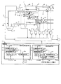
図1は本発明の液体噴射装置の一例としてのプリンタ装置の構成を示す。
図1に示すように、液体噴射装置として、例えば、プリンタ装置1は、液体としてのイ
ンクI(以下、符号を付さずにインクという)を収容するインクタンク2(以下、タンク
という)と、液体としてのインクを収容するインクカートリッジ3(以下、カートリッジ
という)と、インクを噴射するヘッド4と、ヘッド4経由でタンク2とカートリッジ3と
を連通させる主連通路5Aと、ヘッド4を経由しないでタンク2とカートリッジ3とを連
通させる副連通路5Bと、タンク側ポンプP1と、タンク側空気開閉弁V1と、カートリ
ッジ側ポンプP2と、カートリッジ側空気開閉弁V2と、タンク側インク出口開閉弁V3
と、カートリッジ側インク出口開閉弁V4と、副連通路開閉弁V5a,V5bと、検出手
段としての流量センサQ1;Q2と、制御手段11とを備える。本形態では、カートリッ
ジ3を第1液体収容部とし、タンク2を第2液体収容部として定義する。
FIG. 1 shows a configuration of a printer apparatus as an example of a liquid ejecting apparatus of the present invention.
As shown in FIG. 1, as a liquid ejecting apparatus, for example, a
A cartridge side ink outlet on / off valve V4, sub-communication path on / off valves V5a, V5b, a flow rate sensor Q1; Q2 as a detecting means, and a control means 11. In this embodiment, the
第2液体収容部としてのタンク2と第1液体収容部としてのカートリッジ3とがヘッド
4経由の主連通路5Aによって連通するように構成され、この主連通路5Aを介してタン
ク2とカートリッジ3との間でインクを相互に補給し合う。タンク2とカートリッジ3と
がヘッド4を介さないで(経由しないで)副連通路5Bによって連通するように構成され
、この副連通路5Bを介してタンク2とカートリッジ3との間でインクを相互に補給し合
う。副連通路5Bは、タンク2よりヘッド4に連通するタンク側主連通路21と、カート
リッジ3よりヘッド4に連通するカートリッジ側主連通路41とにより形成される。
つまり、タンク2とカートリッジ3との間でインクを往復移動させることによってイン
クを攪拌させる動作を、並列通路である主連通路5Aと副連通路5Bとでそれぞれ別々に
行えるように構成した。即ち、インクを攪拌させるための2つの独立したインク通路とし
て、主連通路5Aと副連通路5Bとを備えた。
制御手段11は、タンク2及びカートリッジ3のうちのいずれか一方から主連通路5A
あるいは副連通路5B経由で他方にインクを補給する場合に、インクを補給する側のイン
クが所定量、例えば空状態又は空に近い状態に減少するまで補給する制御を行う。この制
御については、後述する。
The
That is, the operation of stirring the ink by reciprocating the ink between the
The control means 11 is connected to the
Alternatively, when ink is supplied to the other side via the
図6はタンク2、カートリッジ3、ヘッド4の関係を断面で示す。
図6に示すように、タンク2は、プリンタ装置1の可動部であるキャリッジ(ヘッド取
付部)IKに固定状態又は着脱可能に取り付けられ、本例ではインクが消費されることに
よって交換されるタイプではないが、交換されるタイプであってもよい。タンク2は、タ
ンク側圧力室13を形成する容器15と、タンク側圧力室13内に設けられたインク(液
体)収容体としての収容袋体16とを備える。容器15は、硬質プラスチックのような非
通気性の硬質材料により形成され、後述する袋側主インク出入口部20を保持する容器側
主インク出入口部17と、後述する袋側副インク出入口部20aを保持する容器側副イン
ク出入口部17aと、タンク側圧力室13内を外部と連通可能とする空気取込口部18と
、タンク側圧力室13内を外部と連通可能とする空気排出口部19とを備える。収容袋体
16は、インクを大気に開放しない状態で収容するものであって、ブチルゴム、多硫化ゴ
ム、エピクロロヒドリンゴム、高ニトリルゴム、フッ素ゴムなどのように、可撓性、かつ
、非気体透過性を有した材料により形成されたインク収容容積可変型の薄形の袋より成り
、袋側主インク出入口部20と袋側副インク出入口部20aとを備える。袋側主インク出
入口部20が容器側主インク出入口部17を通過して容器15の外部に臨むように容器1
5に固定され、かつ、インクがタンク側主連通路21と収容袋体16とに連通可能となる
ようにタンク側主連通路21の一端開口部と収容袋体16の袋側主インク出入口部20と
が連結される。また、袋側副インク出入口部20aが容器側副インク出入口部17aを通
過して容器15の外部に臨むように容器15に固定され、かつ、インクが副連通路5Bと
収容袋体16とに連通可能となるように副連通路5Bの一端開口部と収容袋体16の袋側
副インク出入口部20aとが連結される。
FIG. 6 shows the relationship among the
As shown in FIG. 6, the
5 and the one end opening of the tank side
また、空気をタンク側圧力室13内に供給可能なように、空気供給路23の他端開口部
と空気取込口部18とが連結され、空気供給路23の一端開口部とタンク側ポンプP1の
吐出口部26とが連結される。タンク側ポンプP1の吸込口部22は大気に開放される。
タンク側圧力室13内を大気開放又は大気遮断可能なように、空気排出路27の他端開口
部と空気排出口部19とが連結され、空気排出路27の一端開口部とタンク側空気開閉弁
V1とが連結される。流量センサQ1は、タンク側インク出口開閉弁V3は、タンク側主
連通路21内を流れるインクの流量を計測可能なように、タンク側主連通路21に取り付
けられる。タンク側インク出口開閉弁V3は、タンク側主連通路21における袋側副イン
ク出入口部20aの近傍においてタンク側主連通路21を開閉可能なようにタンク側主連
通路21に取り付けられる。
Further, the other end opening of the
The other end opening of the
カートリッジ3は、プリンタ装置1の基体に着脱可能に取り付けられる。本例では、カ
ートリッジ3は、インクが消費されることによって交換されるものである。カートリッジ
3は、カートリッジ側圧力室33を形成する容器35と、カートリッジ側圧力室33内に
設けられたインク(液体)収容体としての収容袋体36とを備える。容器35は、硬質プ
ラスチックのような非通気性の硬質材料により形成され、後述する袋側主インク出入口部
40を保持する容器側主インク出入口部37と、後述する袋側副インク出入口部40aを
保持する容器側副インク出入口部37aと、カートリッジ側圧力室33内を外部と連通可
能とする空気取込口部38と、カートリッジ側圧力室33内を外部と連通可能とする空気
排出口部39とを備える。収容袋体36は、インクを大気に開放しない状態で収容するも
のであって、ブチルゴム、多硫化ゴム、エピクロロヒドリンゴム、高ニトリルゴム、フッ
素ゴムなどのように、可撓性、かつ、非気体透過性を有した材料により形成されたインク
収容容積可変型の薄形の袋より成り、袋側主インク出入口部40と袋側副インク出入口部
40aとを備える。袋側主インク出入口部40が容器側主インク出入口部37を通過して
容器35の外部に臨むように容器35に固定され、かつ、インクがカートリッジ側主連通
路41と収容袋体36とに連通可能なようにカートリッジ側主連通路41の一端開口部と
収容袋体36の袋側主インク出入口部40とが連結される。また、袋側副インク出入口部
40aが容器側副インク出入口部37aを通過して容器15の外部に臨むように容器15
に固定され、かつ、インクが副連通路5Bと収容袋体36とに連通可能となるように副連
通路5Bの他端開口部と収容袋体36の袋側副インク出入口部40aとが連結される。
The
The other end opening of the
また、空気をカートリッジ側圧力室33内に供給可能なように、空気供給路43の他端
開口部と空気取込口部38とが連結され、空気供給路43の一端開口部とカートリッジ側
ポンプP2の吐出口部46とが連結される。カートリッジ側ポンプP2の吸込口部42は
大気に開放される。カートリッジ側圧力室33内を大気開放又は大気遮断可能なように、
空気排出路47の他端開口部と空気排出口部39とが連結され、空気排出路47の一端開
口部とカートリッジ側空気開閉弁V2とが連結される。カートリッジ側インク出口開閉弁
V4は、カートリッジ側主連通路41における袋側主インク出入口部40の近傍において
カートリッジ側主連通路41を開閉可能なようにカートリッジ側主連通路41に取り付け
られる。流量センサQ2は、副連通路5B内を流れるインクの流量を計測可能なように、
副連通路5Bに取り付けられる。副連通路開閉弁V5a,V5bは、副連通路5Bを開閉
可能なように副連通路5Bに取り付けられる。副連通路開閉弁V5aは、副連通路5Bの
一端開口部の近傍に設けられ、副連通路開閉弁V5bは、副連通路5Bの他端開口部の近
傍に設けられる。
Further, the other end opening of the
The other end opening of the
It is attached to the
本例では、タンク2とカートリッジ3とは、カートリッジ3が交換可能という点で異な
るだけで、その他の構成は同じである。なお、カートリッジ3は未使用状態においては袋
側主インク出入口部20が図外の封止膜により封止されている。そして、カートリッジ側
主連通路41の一端開口部には図外のインク供給針が設けられている。
以上のような構成において、カートリッジ3がプリンタ装置1に取り付けられた場合に
、インク供給針が封止膜を破り、これにより、カートリッジ3の収容袋体36内のインク
がインク供給針の中空路及びカートリッジ側主連通路41を経由してヘッド4に供給され
ることになる。カートリッジ3の交換時には、カートリッジ側インク出口開閉弁V4が制
御手段11により閉じられる。カートリッジ3は、キャリッジIKに取り付けられるもの
であっても良い。なお、新たなカートリッジ3が装着されると、図外のスイッチが入り後
述の液体相互補給の動作が開始される。
In this example, the
In the above-described configuration, when the
ヘッド4は、インク室24と、圧力室25と、液体噴射吐出口としてのノズル28と、
アクチュエータ30とを備える。インク室24の一端開口部とタンク側主連通路21の他
端開口部とが連通可能に繋がれ、インク室24の他端開口部とカートリッジ側主連通路4
1の他端開口部とが連通可能に繋がれる。即ち、タンク2とカートリッジ3とをヘッド4
を経由して連通させる主連通路5Aが、タンク2とインク室24とを連通させるタンク側
主連通路21と、カートリッジ3とインク室24とを連通させるカートリッジ側主連通路
41と、タンク側主連通路21とカートリッジ側主連通路41とを連通させるインク路と
なるインク室24とにより構成される。圧力室25の一端開口部はインク室24と連通し
、圧力室25の他端開口部はノズル28と連通する。アクチュエータ30は、圧力室25
の壁に設けられたピエゾ素子やヒータ素子などにより形成される。
The
And an
The other end opening of 1 is connected to be able to communicate. That is, the
A
It is formed by a piezo element or a heater element provided on the wall.
ヘッド4では、インク室24から圧力室25内に供給されたインクがノズル28の出口
にインクの凹面(メニスカス)を形成し、アクチュエータ30の作用によってノズル28
内のインクを押し出してドロップを形成し、ドロップが印刷対象物に被着することによっ
て、紙などの印刷対象物に対する印刷が行われる。
In the
The ink in the inside is extruded to form a drop, and the drop adheres to the print target, whereby printing on the print target such as paper is performed.
副連通路5B内には、図7に示すような、邪魔板と呼ばれる攪拌板65が設置される。
図7(a)の攪拌板65Aは、中心軸66の軸周りに螺旋路を形成する螺旋体67が中心
軸の延長方向に沿って複数連続するように中心軸66に取り付けられたことで、連続しな
い複数の螺旋路を有した構成を備え、この連続しない複数の螺旋路がインクの流れを邪魔
するように構成されたものである。図7(b)の攪拌板65Bは、線材68を組み合わせ
て形成され、線材68がインクの流れを邪魔するように構成されたものである。つまり、
攪拌板65は、インクの流れを邪魔することでインクに乱流を生じさせてインクを攪拌さ
せるものである。
A stirring
The stirring
The stirring
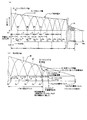
図2は主連通路5Aを介した噴射時における相互補給制御の際の、タンク2内インク量
ITとカートリッジ3内インク量ICの変化と、タンク2内インク量ITとカートリッジ
3内インク量ICとの合算値であるインク総和量IKの変化及び後述のパルスP(パルス
Pa,Pb)の発生タイミングを示す。
流量センサQ1により、タンク2,カートリッジ3内の空状態が検出される。すなわち
、流量センサQ1は、タンク2内インク量IT又はカートリッジ3内インク量ICが図2
に示すように相互に大,小に変化して所定値(所定量)としての空状態まで減少し、イン
クの吐出が無くなると、往路ルートA又は復路ルートBの主連通路5A及びヘッド4内に
インクが残留していても、主連通路5A内のインクの流れが停止されるので、このとき流
量が「0」として検出され、タンク2内、カートリッジ3内の所定量としての空状態を示
すパルスP(パルスPa,パルスPb)を流量センサQ1より出力する。なお、パルスP
aは、ルートAでインクの補給がカートリッジ3よりタンク2に行われているとき、カー
トリッジ3内インク量ICが空状態となり、インクの補給がされなくなった時、流量セン
サQ1より出力される。パルスPbはルートBでインクの補給がタンク2よりカートリッ
ジ3に行われているとき、タンク2内インク量ITが空状態となり、インクの補給がされ
なくなった時、流量センサQ1より出力される。流量センサQ1はこのように双方向流量
検知器より成り、かつ、主連通路5Aを介した噴射時における相互補給制御の際に、タン
ク2内インク量IT又はカートリッジ3内インク量ICが空状態となるとパルスP(パル
スPa、パルスPb)を出力するパルス回路を有する。
FIG. 2 shows changes in the ink amount IT in the
An empty state in the
As shown in FIG. 5, when the ink changes to large and small and decreases to an empty state as a predetermined value (predetermined amount) and ink is not discharged, the
A is output from the flow rate sensor Q1 when the ink amount IC in the
図4は副連通路5Bを介した噴射停止時における相互補給制御の際の、タンク2内イン
ク量ITとカートリッジ3内インク量ICの変化と後述のパルスP(パルスPc,Pd)
の発生タイミングを示す。
流量センサQ2により、タンク2,カートリッジ3内の空状態が検出される。すなわち
、流量センサQ2は、タンク2内インク量IT又はカートリッジ3内インク量ICが図4
に示すように相互に大,小に変化して所定値(所定量)としての空状態まで減少し、往路
ルートC又は復路ルートDを形成する副連通路5B内のインクの流れがなくなった場合に
、流量が「0」として検出され、タンク2内、カートリッジ3内の所定量としての空状態
を示すパルスP(パルスPc,パルスPd)を流量センサQ2より出力する。なお、パル
スPcは、図4に示すようにルートCでインクの補給がカートリッジ3よりタンク2に行
われているとき、カートリッジ3内インク量ICが空状態となり、インクの補給がされな
くなった時、流量センサQ2より出力される。パルスPdはルートDでインクの補給がタ
ンク2よりカートリッジ3に行われているとき、タンク2内インク量ITが空状態となり
、インクの補給がされなくなった時、流量センサQ2より出力される。流量センサQ2は
このように双方向流量検知器より成り、かつ、副連通路5Bを介した噴射停止時における
相互補給制御の際に、タンク2内インク量IT又はカートリッジ3内インク量ICが空状
態となるとパルスP(パルスPc、パルスPd)を出力するパルス回路を有する。本形態
では往路ルートCを第1の液体補給ルートとし、復路ルートDを第2の液体補給ルートと
して定義する。
FIG. 4 shows changes in the ink amount IT in the
The timing of occurrence is shown.
An empty state in the
As shown in FIG. 4, when the ink flow changes to large and small and decreases to an empty state as a predetermined value (predetermined amount), the ink flow in the
なお、最良の形態で使用する流量センサQ1,Q2は、流量があるか否かのみを検出可
能であるが、パルス回路が無く、この流量をアナログ信号として制御手段11に出力する
タイプのものであっても良い。この場合、制御手段11はアナログ信号の最小値を検出し
て空状態又は後述の所定量に達したことを検出(後述の判断1と判断2とを検出)して、
所定の処理を行う。
The flow rate sensors Q1 and Q2 used in the best mode can detect only whether or not there is a flow rate. However, the flow rate sensors Q1 and Q2 have no pulse circuit and output this flow rate to the control means 11 as an analog signal. There may be. In this case, the control means 11 detects the minimum value of the analog signal and detects that it has reached an empty state or a predetermined amount described later (
Perform predetermined processing.
制御手段11は、図1に示すように、噴射時制御手段11Aと噴射停止時制御手段11
Bとを備える。噴射時制御手段11Aは、往路補給制御手段(往路ルートA設定)51、
復路補給制御手段(復路ルートB設定)52、相互補給制御手段53、パルス検出手段5
4、インク残量判定手段55とを備える。噴射停止時制御手段11Bは、往路補給制御手
段(往路ルートC設定)51a、復路補給制御手段(復路ルートD設定)52、相互補給
制御手段53a、パルス検出手段54aとを備える。
As shown in FIG. 1, the control means 11 includes an injection time control means 11A and an injection stop time control means 11.
B. The injection time control means 11A includes an outward supply control means (outward route A setting) 51,
Return route supply control means (return route B setting) 52, mutual supply control means 53, pulse detection means 5
4 and a remaining ink
まず、噴射時制御手段11Aの構成、動作、制御を説明する。パルス検出手段54は、
流量センサQ1からのパルスP(パルスPa,パルスPb)を相互に検出するとともに、
相互補給制御手段53は、パルス検出手段54からの出力にもとづき、往路補給制御手段
51と復路補給制御手段52のいずれか一方を交互に駆動して、補給ルートを、ルートA
又はルートBに交互に設定する。インク残量判定手段55は、後述するステップS7を実
行することによって、図2に示すインク総和量IK(ほぼカートリッジ内に残っているカ
ートリッジ内インク量ICとタンク内に残っているタンク内インク量ITとの総和量IK
)を、後述の判定方法で検出し、かつ、この検出値が設定インク残量Wまで低下したか否
かを判別する。なお、噴射時制御手段11Aは、入出力インターフェース45を介してポ
ンプP1,P2のドライバ50や開閉弁V1乃至V5a,V5bのドライバ58に出力さ
れ、制御値に基いてドライバがポンプP1,P2や開閉弁V1乃至V5a,V5bを制御
することで、往路ルートA,復路ルートBが形成される。
First, the configuration, operation, and control of the injection time control means 11A will be described. The pulse detection means 54
While detecting mutually the pulse P (pulse Pa, pulse Pb) from the flow sensor Q1,
Based on the output from the pulse detection means 54, the mutual supply control means 53 alternately drives one of the forward supply control means 51 and the backward supply control means 52 to set the supply route to the route A.
Alternatively, the route B is alternately set. The ink remaining
) Is detected by a determination method described later, and it is determined whether or not the detected value has decreased to the set ink remaining amount W. The injection-time control means 11A is output to the
図1,図2において、ルートAが形成されている状態で、第1液体収容部としてのカー
トリッジ3内インク量ICが空状態となると、流量センサQ1よりパルスPaが出力され
、復路補給制御手段52が駆動されてルートBに切換え設定され、このルートBでインク
がタンク2からカートリッジ3に送られる。このルートBにおいて、今度はタンク2内イ
ンク量ITが空状態となると、パルスPbが出力されて往路補給制御手段51が駆動され
ルートAに切換えられる。ルートAにおいて、カートリッジ3内インク量ICが空状態と
なるとパルスPaが出力されるので、以下同様の動作が繰り返される。すなわち、相互補
給動作が行われる。このように、往路ルートAと復路ルートBとが交互に形成されてイン
クがカートリッジ3とタンク2との間で複数回往復移動するので、ヘッド4によりインク
が消費されると同時にインクが攪拌されてインクの澱みや付着が防止されてインクの濃度
を適正に維持できるとともに、インクの色成分の沈降を防止できる。なお、相互補給に際
し、ヘッド4によりインクが噴射されるので、時間経過によりインクが消耗し、インク総
和量IKが漸減して行く。図2(c)の概略図に示すように、相互補給の終期では、イン
クがヘッド4より噴射されて消耗され、インク総和量IKが減少して相互補給の終期にな
ると、インク総和量IKとしてのインク残量があらかじめ設定しておいた残量Wになると
、相互補給動作を停止する。なお、インク総和量IKがこの設定のインク残量Wに達した
か否かは、後述するようにインク残量判定手段55により、パルスPa,Pbが設定個数
Nカウントされたか否かにより検出される。つぎに、インクをタンク2内に全量移送させ
相互補給停止後の流量センサQ1からのエンドパルスPae(パルスPaのエンドパルス
)にもとづき、インクエンド予備警告表示を行う。これによりカートリッジ3の交換を促
す。以降はタンク2に移送されたインクの残量が消耗されるようにして、ヘッド4での空
打ち動作を防止できるようにした。タンク2内の残留インクが消費されて「0」となると
、最後にエンドパルスPbe(パルスPbのエンドパルス)が発生され、これでインクエ
ンド本表示がなされ、インク切れを表示する。流量センサQ1はこのようにインク総和量
IKがインク残量Wになって相互な補給動作が停止されても、エンドパルスPae,Pb
eを発生させる為に、活性化されている。
1 and 2, when the ink amount IC in the
It is activated to generate e.
噴射時の相互補給制御を図3に示すフローを用いて説明する。まず、ステップS0で、
制御手段11が、噴射停止(ヘッドによる印字動作の停止)か否かを判定する。制御手段
11は、噴射停止ではないと判定した場合(ステップS0でNo(噴射時(印字中)))
、制御を噴射時制御手段11Aに移行し、噴射時制御手段11Aは、ステップS1におい
て、副連通路開閉弁V5a,V5bを閉じ、タンク側インク出口開閉弁V3及びカートリ
ッジ側インク出口開閉弁V4を開き、タンク側ポンプP1とカートリッジ側ポンプP2と
を共に停止させた状態で、タンク側開閉弁V1を開いてタンク側圧力室13を大気に開放
し、カートリッジ側開閉弁V2を閉じてカートリッジ側圧力室33と大気とを遮断してカ
ートリッジ側圧力室33を密室に保つ。ステップS2でカートリッジ側ポンプP2を駆動
してカートリッジ側圧力室33内を加圧する。これにより、ルートAが形成され、カート
リッジ側圧力室33内の圧力によってカートリッジ側インク収容袋体36が押圧されてカ
ートリッジ側インク収容袋体36内のインクが主連通路5Aに送り出されてヘッド4及び
タンク側インク収容袋体16側に移動する。噴射時制御手段11Aは、このルートAの補
給制御においてステップS3で、流量がある場合(ステップS3でYes)、カートリッ
ジ側インク収容袋体36内のインク量IC(カートリッジ内インク量ICという)が空状
態になっていないと判断して、カートリッジ側ポンプP2の駆動を継続してカートリッジ
側圧力室33内の加圧を継続することによってルートAの往路補給制御を続行する(ステ
ップS2)。噴射時制御手段11Aは、ステップS3において、カートリッジ内インク量
ICが空状態となって、インクの流量がなくなると流量センサQからパルスPaを出力し
てパルス検出手段54がこのパルスPaを検出した場合に(ステップS3でNoと判断;
判断1)、カートリッジ側インク量が所定量としての空状態になったと判断(パルスPa
発生)して、カートリッジ側ポンプP2を停止し、カートリッジ側開閉弁V2を開いてカ
ートリッジ側圧力室33を大気に開放し、タンク側開閉弁V1を閉じてタンク側圧力室1
3と大気とを遮断してタンク側圧力室13を密室に保つことにより(ステップS4)、ル
ートAの往路補給制御を終了する。同時に、ステップS5で上記パルスPaによりルート
Bを形成し、タンク側ポンプP1を駆動してタンク側圧力室13内を加圧する。即ち、復
路ルートB経由の復路補給制御を開始する。噴射時制御手段11Aは、ステップS6にお
いて、流量がある場合、即ち、流量センサQからのパルスPbを入力しない場合は(ステ
ップS6でYes)、タンク側インク収容袋体36内のインク量ITが空状態になってい
ないと判断し、タンク側ポンプP1の駆動を継続してタンク側圧力室13内の加圧を継続
することによって復路補給制御を続行する(ステップS5)。噴射時制御手段11Aは、
ステップS6において、タンク内インク量ITが空状態となって、インクの流量がなくな
ると流量センサQからパルスPbを出力してパルス検出手段54がこのパルスPbを検出
した場合に(ステップS6でNo判断;判断2)、ステップS7に移行し、ステップS7
では、インク残量判定手段55によってインクがインク残量Wまで低下したか否かの判定
が行われる。
Mutual replenishment control during injection will be described with reference to the flow shown in FIG. First, in step S0,
The control means 11 determines whether or not ejection is stopped (stop of printing operation by the head). When the control means 11 determines that the injection is not stopped (No in step S0 (during injection (during printing)))
In step S1, the injection control means 11A closes the sub-communication passage opening / closing valves V5a and V5b and opens the tank-side ink outlet opening / closing valve V3 and the cartridge-side ink outlet opening / closing valve V4. Open, with the tank side pump P1 and the cartridge side pump P2 both stopped, the tank side on / off valve V1 is opened to open the tank
Determination 1), it is determined that the ink amount on the cartridge side has become a predetermined empty state (pulse Pa)
The cartridge side pump P2 is stopped, the cartridge side on-off valve V2 is opened to open the cartridge
3 and the atmosphere are shut off and the tank-
In step S6, when the ink amount IT in the tank becomes empty and the ink flow rate is exhausted, a pulse Pb is output from the flow rate sensor Q, and the pulse detection means 54 detects this pulse Pb (No in step S6). Judgment; Judgment 2), the process proceeds to step S7, and step S7
Then, the ink remaining
インク残量判定手段55によりインク総和量IK、すなわちインクの残量の判定を行う
方法として、ステップS7では、一定(単位)時間F内に判断1と判断2とが何回繰り返
されたかをカウントし、このカウント値が設定回数Nに達したか否かで判定する。(パル
スPa,Pbをカウントし、このカウント値が設定個数Nに達するか否かの判定でも良い
)ステップS7の判断でNoと判断された場合には、リターンし、ルートAによる往路補
給制御とルートBによる復路補給制御とを流量センサQ1からのパルスP(パルスPa、
パルスPb)にもとづき相互に繰り返す相互補給制御が実行される。なお、相互補給制御
と印刷動作制御とは並行して同時に実行され、主連通路5A内を経由するインクの一部が
ヘッド4のインク室24に供給されて印刷に消費される為、相互補給制御が進行するに従
ってインク総和量IK、即ち、プリンタ装置1に残る全インク量は減少する(図2参照)
。よって、相互補給制御が進行し、インクがヘッド4のインク室24に供給されて印刷に
さらに消費されるとカートリッジ内インク量IC又はタンク内インク量ITが空状態とな
る時間間隔Tが短くなり、ステップS3でのNoという判断1とステップS6でのNoと
いう判断2とが繰り返される周期が次第に短くなる。つまり、あらかじめ設定された一定
(単位)時間F当りの判断1と判断2との繰返し回数すなわちパルスP(パルスPa,パ
ルスPb)の発生回数が多くなる。そこで、ステップS7において、制御手段11が、一
定時間F内に判断1と判断2とを設定回数N繰り返したと判定する(ステップS7でYe
sと判定する)ことによって、インク総和量IKとしてのインク残量があらかじめ決めら
れた設定インク残量Wになったと判定してステップS8に移行して、相互補給を停止する
。その後、以下の各ステップでカートリッジを交換できるようにするための交換準備制御
を行う。なお、ステップS7での判定は、ステップS6でNOと判断された直後に行われ
るので、タンク内インク量ICが空状態である。
なお、一定(単位)時間Fの長さは図2に示すように時間を一定長さで時分割して得ら
れ、この一定(単位)時間F内に判断1と判断2とが何回繰り返されたか否か(パルスP
aとパルスPbとが設定個数Nに達したか否か)の判定が行われる。当該時間Fを形成す
る方法としては、単安定マルチバイブレータ等を用いることで容易に構成でき当該単安定
マルチバイブレータの出力を相互補給開始時にスタートさせることにもとづき、この出力
の時間Fにおいて、図外のカウンタを活性化させ、この時間F内に活性化されるカウンタ
により、判断1と判断2(パルスPa,パルスPb)をカウントして、設定時間F内に達
したか否かを判定することでインク残量(タンク内インク量ITとカートリッジ内インク
量ICとのインク総和量IK)が設定インク残量Wにまで低下したか否かを判定できる。
なお、設定回数Nは、設定インク残量Wをどのような大きさに設定するかどうかで決定さ
れる。なお、時間間隔Tがあらかじめ設定した長さに達するかどうかを判定することによ
っても総和量IKすなわち、インク残量を検出できる。
As a method of determining the total ink amount IK, that is, the ink remaining amount by the ink remaining
Mutual replenishment control is performed based on the pulse Pb). The mutual supply control and the printing operation control are executed simultaneously in parallel, and a part of the ink passing through the
. Accordingly, when the mutual replenishment control proceeds and ink is supplied to the
s), it is determined that the ink remaining amount as the total ink amount IK has reached the predetermined set ink remaining amount W, and the process proceeds to step S8 to stop the mutual supply. Thereafter, replacement preparation control is performed so that the cartridge can be replaced in the following steps. Note that the determination in step S7 is performed immediately after NO is determined in step S6, so the ink amount IC in the tank is empty.
Note that the length of the fixed (unit) time F is obtained by time-sharing the fixed time as shown in FIG. 2, and the
Whether or not a and the pulse Pb have reached the set number N is determined. The method of forming the time F can be easily configured by using a monostable multivibrator or the like, and the output of the monostable multivibrator is started at the start of mutual supply. And the counter activated within this time F is used to count
Note that the set number N is determined depending on the size of the set ink remaining amount W. Note that the total amount IK, that is, the remaining ink amount can also be detected by determining whether or not the time interval T reaches a preset length.
また、この判定値である設定インク残量Wは、使用するインクの粘度、環境温度に応じ
て補正される。制御手段11は、インク残量判定値とインクの粘度とを対応付けた補正テ
ーブル、及び、インク残量判定値と環境温度とを対応付けた補正テーブルを備える。そし
て、制御手段が入力したインクの粘度、環境温度を補正テーブルに照合して判定値である
設定インク残量Wにもとづき設定回数Nを設定する。
つぎに、カートリッジを交換できるようにするためのカートリッジ交換準備制御につい
て説明する。ステップS7での判定でYesと判断された後、噴射時制御手段11Aは、
ステップS8で、各ポンプP1,P2を停止し、タンク側開閉弁V1を開いてタンク側圧
力室13を大気に開放し、カートリッジ側開閉弁V2を閉じて、相互補給を停止する(流
量センサQ1は活性状態としておく)。ステップS9でカートリッジ側ポンプP2を駆動
してカートリッジ側圧力室33内を加圧する。そして、噴射時制御手段11Aは、ステッ
プS10において、流量センサQから空状態すなわち流量「0」を入力するまで、カート
リッジ側ポンプP2を駆動してカートリッジ側圧力室33内を加圧し続ける。
ステップS10において、噴射時制御手段11Aは、カートリッジ3内に残っていたイ
ンクをカートリッジ3内から副連通路5B内及びタンク2内に移動させてカートリッジ内
インク量ICが空状態となったと判定した場合(ステップS10でNo)には、ステップ
S11でインクエンド予備警告表示を行う。ステップS9,S10によりカートリッジ3
のインクが全てタンク2に移送されるので、カートリッジ3が空に設定され、カートリッ
ジ3を交換しても無駄にインクが捨てられることがなくなる。相互補給停止の直後カート
リッジ3を空にすると、エンドパルスPaが出力され、「インクがもうすぐ切れます」等
の予備表示をステップS11で表示する。この予備表示は上記補給動作停止時でも良い。
ステップS12ではカートリッジ3が交換されない場合でも、カートリッジ3から移され
たタンク2内のインクの残量が消費されるので、空打ちを防止できる。そして、ステップ
S12でタンク2のインク残量が無くなったと判定されると、ステップS13でポンプP
1,ポンプP2を停止し、タンク側開閉弁V1と、カートリッジ側開閉弁V2を閉じ完全
停止となる。つぎに、プリンタ装置1の基体に設けられたインクエンド表示器57にイン
クエンド本表示を行い(ステップS14)、使用者は、このインクエンド本表示、例えば
「インク切れの為使えません」等の表示を確認して印刷停止となったことを判別できる。
従って、インクエンド表示器57によりインクエンドの予備表示が行われたときに、カー
トリッジ3が交換されれば問題は無いが、交換がされなくても、タンク2にインクが移送
されて、このインクが消費されることで空打ちは防止できる。
The set ink remaining amount W, which is the determination value, is corrected according to the viscosity of the ink to be used and the environmental temperature. The
Next, cartridge replacement preparation control for enabling cartridge replacement will be described. After it is determined Yes in step S7, the injection time control means 11A
In step S8, the pumps P1 and P2 are stopped, the tank side opening / closing valve V1 is opened to open the tank
In step S10, the ejection time control means 11A moves the ink remaining in the
Since all of the ink is transferred to the
Even if the
1. The pump P2 is stopped, the tank side on-off valve V1 and the cartridge side on-off valve V2 are closed, and the pump is completely stopped. Next, the ink end book display is performed on the
Accordingly, there is no problem if the
なお、カートリッジ3の収容袋体36のインク収容最大容積は、タンク2の収容袋体1
6のインク収容最大可能容積よりも小さい。これは、カートリッジ3の装着時にカートリ
ッジ3のインク全量をタンク2内に補給できるようにしてタンク2からのインクの溢れ出
しが生じないようにする為である。また、タンク2に設定インク残量W分のインクを残留
インクとして残した状態で新規な、カートリッジ3内のインクが全量移された場合にもタ
ンク2よりインクの溢れ出しが生じないようにする為である。
Note that the maximum ink storage capacity of the
6 is smaller than the maximum capacity of ink storage. This is to prevent the overflow of ink from the
次に、噴射停止時制御手段11Bの構成、動作、制御を説明する。パルス検出手段54
aは、流量センサQ2からのパルスP(パルスPc,パルスPd)を相互に検出するとと
もに、相互補給制御手段53aは、パルス検出手段54aからの出力にもとづき、往路補
給制御手段51aと復路補給制御手段52aのいずれか一方を交互に駆動して、副連通路
5Bを介した補給ルートを、ルートC又はルートDに交互に設定する。まず、副連通路5
Bを介した往路ルートCでカートリッジ3よりタンク2にカートリッジ3のインク量IC
が空(0レベル)となるまでインクが補給される。逆に副連通路5Bを介した復路ルート
Dでタンク2よりカートリッジ3にタンク2のインク量ITが空となるまでインクが補給
される。このルートC及びルートDによるインクの補給動作が繰り返される。これにより
、タンク2とカートリッジ3とに交互にインクが補給され、攪拌される。特に、副連通路
5B内には攪拌板65が設けられているので、往路ルートC又は復路ルートDを介したイ
ンク補給動作によるインク攪拌効果は高い。
Next, the configuration, operation, and control of the injection stop time control means 11B will be described. Pulse detection means 54
a detects mutually the pulse P (pulse Pc, pulse Pd) from the flow sensor Q2, and the mutual supply control means 53a is based on the output from the pulse detection means 54a, and the forward supply control means 51a and the return supply control. Either one of the
Ink amount IC of the
Ink is supplied until becomes empty (0 level). Inversely, ink is supplied from the
図4に示すように、インク量IC、ITが空となる毎に液量センサQ2からのパルスP
c,Pdが出力され、このパルスにもとづき噴射停止時制御手段11Bは、往路ルートC
と復路ルートDの交互切換えを行う。すなわち、噴射停止時制御手段11Bは、副連通路
5Bを介して第1液体収容部としてのタンク2より第2液体収容部としてのカートリッジ
3に液体としてのインクを補給する第1の液体補給ルートとしての復路ルートDと、副連
通路5Bを介して第2液体収容部としてのカートリッジ3より第1液体収容部としてタン
ク2に液体としてのインクを補給する第2の液体補給ルートとしての往路ルートCを設定
するとともに、往路ルートCでカートリッジ3よりタンク2にインクを補給する第2の液
体補給制御としての往路補給制御と、復路ルートDでタンク2よりカートリッジ3にイン
クを補給する第1の液体補給制御としての復路補給制御とを交互に切換える。なお、スタ
ートタイマTxは、噴射停止(印字停止)から所定時間経過後、例えば、噴射停止(印字
停止)から24時間後、あるいは、1週間後にスタート信号Stを発生する。
As shown in FIG. 4, every time the ink amount IC, IT becomes empty, the pulse P from the liquid amount sensor Q2
c and Pd are output, and based on this pulse, the injection stop time control means 11B
And return route D are alternately switched. That is, the ejection stop time control means 11B supplies the ink as the liquid from the
噴射停止時の相互補給制御を図5に示すフローを用いて説明する。なお、噴射停止時と
は、電源オフ時又は、電源オンでも液体噴射ヘッドがキャッピング位置に停止している場
合も含む。また、長期間、例えば何ヶ月も装置として不使用状態に置かれる場合も含む。
制御手段11は、図3のステップS0で、噴射停止(印字停止)である判定した場合(ス
テップS0でYes)、制御を噴射停止時制御手段11Bの制御に移行し、噴射停止時制
御手段11Bは、スタートタイマTxをセットする(ステップS20)。スタートタイマ
Txは、セットされてから所定時間経過後(例えば、24時間後や1週間後)にスタート
信号Stを噴射停止時制御手段11Bに出力する。ステップS21では、噴射停止時制御
手段11Bの相互補給制御手段53aが、上記スタート信号Stを入力したか否かを判定
する。相互補給制御手段53aが、スタート信号Stを入力しない場合は(ステップS2
1でNo)、スタート信号Stを入力するまで待機する。スタート信号Stを入力した場
合(ステップS21でYes)は、ステップS22で、タンク側インク出口開閉弁V3及
びカートリッジ側インク出口開閉弁V4を閉じ、副連通路開閉弁V5a,V5bを開き、
また、タンク側ポンプP1とカートリッジ側ポンプP2とを共に停止させた状態で、タン
ク側開閉弁V1を開いてタンク側圧力室13を大気に開放し、カートリッジ側開閉弁V2
を閉じてカートリッジ側圧力室33と大気とを遮断してカートリッジ側圧力室33を密室
に保つ。相互補給制御手段53aは、ステップS23で、カートリッジ側ポンプP2を駆
動してカートリッジ側圧力室33内を加圧する。これにより、往路ルートCが形成され、
カートリッジ側圧力室33内の圧力によってカートリッジ側インク収容袋体36が押圧さ
れてカートリッジ側インク収容袋体36内のインクが副連通路5Bに送り出されてタンク
側インク収容袋体36側に移動する。相互補給制御手段53aは、この往路ルートCの補
給制御において、流量センサQ2が流量を検出した場合(ステップS24でYes)、カ
ートリッジ側インク収容袋体36内のインク量IC(カートリッジ内インク量ICという
)が空状態になっていないと判断して、カートリッジ側ポンプP2の駆動を継続してカー
トリッジ側圧力室33内の加圧を継続することによって往路ルートC経由の往路補給制御
を続行する(ステップS23)。相互補給制御手段53aは、ステップS24において、
カートリッジ内インク量ICが空状態となって、インクの流量がなくなると流量センサQ
2からパルスPcを出力してパルス検出手段54がこのパルスPcを検出した場合に(ス
テップS24でNoと判断;判断1)、カートリッジ側インク量が所定量としての空状態
になったと判断して、カートリッジ側ポンプP2を停止し、カートリッジ側開閉弁V2を
開いてカートリッジ側圧力室33を大気に開放し、タンク側開閉弁V1を閉じてタンク側
圧力室13と大気とを遮断してタンク側圧力室13を密室に保つことにより(ステップS
25)、往路ルートC(第2の液体補給ルート)経由の往路補給制御(第2の液体補給制
御)を終了する。同時に、ステップS26で上記パルスPcにより復路ルートD(第1の
液体補給ルート)を形成し、タンク側ポンプP1を駆動してタンク側圧力室13内を加圧
する。即ち、復路補給制御手段52aが、復路ルートD経由の復路補給制御(第1の液体
補給制御)を開始する。相互補給制御手段53aは、ステップS27において、流量があ
る場合、即ち、流量センサQ2からのパルスPdを入力しない場合は(ステップS27で
Yes)、タンク側インク収容袋体36内のインク量ITが空状態になっていないと判断
し、タンク側ポンプP1の駆動を継続してタンク側圧力室13内の加圧を継続することに
よって復路ルートD経由の復路補給制御を続行する(ステップS5)。相互補給制御手段
53aは、ステップS27において、タンク内インク量ITが空状態となって、インクの
流量がなくなると流量センサQ2からパルスPdを出力してパルス検出手段54がこのパ
ルスPdを検出した場合に(ステップS6でNo判断;判断2)、ステップS28に移行
し、ステップS28において、判断1と判断2とを予め決められた一定回数だけ繰り返し
たと判定した場合、即ち、往路ルートC経由の往路補給制御と復路ルートD経由の復路補
給制御とを交互に一定回数繰り返した場合に、ステップS29で、ポンプP1,P2を停
止し、開閉弁V1乃至V5a及びV5bを閉じる。
The mutual replenishment control when the injection is stopped will be described using the flow shown in FIG. Note that the time when ejection is stopped includes when the power is turned off or when the liquid ejecting head is stopped at the capping position even when the power is turned on. Moreover, the case where it is left unused as a device for a long period of time, for example, for months, is included.
When it is determined in step S0 in FIG. 3 that the injection is stopped (printing is stopped) (Yes in step S0), the
1), and waits until the start signal St is input. When the start signal St is input (Yes in step S21), in step S22, the tank side ink outlet on / off valve V3 and the cartridge side ink outlet on / off valve V4 are closed, and the auxiliary communication path on / off valves V5a and V5b are opened.
Further, in a state where both the tank side pump P1 and the cartridge side pump P2 are stopped, the tank side opening / closing valve V1 is opened to open the tank
Is closed to shut off the cartridge
The cartridge-side ink containing
When the ink amount IC in the cartridge becomes empty and the ink flow rate is exhausted, the flow rate sensor Q
2 and the pulse detection means 54 detects this pulse Pc (No in Step S24; Determination 1), it is determined that the cartridge-side ink amount has become an empty state as a predetermined amount. The cartridge-side pump P2 is stopped, the cartridge-side on-off valve V2 is opened to open the cartridge-
25) Ends the forward supply control (second liquid supply control) via the forward route C (second liquid supply route). At the same time, the return route D (first liquid supply route) is formed by the pulse Pc in step S26, and the tank
最良の形態1によれば、第1液体収容部としてのカートリッジ3と第2液体収容部とし
てのタンク2との間とでインクを往復移動させるので、インクの澱みや付着が防止されて
インクの濃度を適正に維持できるとともに、インクを補給する側のインク収容体内のイン
クが空状態となるようにインクを絞り切ったので、インクの攪拌効果が大きくなり、イン
クの色成分の沈降を効果的に防止できる。
また、主連通路5Aが、カートリッジ3とタンク2とをヘッド4を介して連通させる構
成であり、副連通路5Bが、カートリッジ3とタンク2とをヘッド4を介さないで連通さ
せる構成を備えるので、噴射時(印字時)及び噴射停止時(印字待機時)のいずれにおい
ても、相互補給制御を行うことで、インクを攪拌させることができる。また、噴射停止時
に副連通路5Bを利用してタンク2とカートリッジ3との間でインクを複数回往復させる
相互補給制御を行うので、長期に渡って印字動作が行われないような場合にも、定期的に
インクを攪拌できる。特に、副連通路5B内には攪拌板65が設けられているので、高い
インク攪拌効果を期待できる。
また、インクが収容袋体16,36内に大気に開放しない状態で収容されたので、イン
ク中の気泡発生を抑制でき、インクの吐出不良や印刷不良を防止できる。
また、双方向タイプの流量センサQ1,Q2を用いたので、インクを補給する側のイン
ク収容体内のインクが空状態となったか否かを一つの流量センサからの出力により正確に
判定できる。また、タンク2及びカートリッジ3が、ポンプP1,P2からの空気圧でイ
ンク収容体内のインクを主連通路5A側に送り出す圧力室13,33を備えたので、相互
補給動作を確実に行える。また、カートリッジ3及びタンク2が、可撓性を有したインク
収容体を備えたので、相互補給動作を確実に行える。
According to the
The
In addition, since the ink is stored in the
In addition, since the bidirectional flow sensors Q1 and Q2 are used, it is possible to accurately determine whether or not the ink in the ink container on the ink supply side has been emptied based on the output from one flow sensor. Further, since the
最良の形態によれば、一定(単位)時間F内に、判断1と判断2とをカウントしてイン
ク量を検出して総和量IKを検出し、この総和量IKに対応するカウント値が設定回数N
だけ繰り返すか否か(パルスPaとパルスPbが設定個数Nに達するか否か)を判定する
ステップS7を実行して、総和量IKが設定インク残量Wに達したか否かを検出するとい
う当該2段階の検出動作を行うインク残量判定手段55を備えた。これにより、設定イン
ク残量Wを正確に検出でき、インクエンド予備警告表示が可能となり、タンク2内に移し
てカートリッジ3を空の状態でカートリッジ3を新規なものと交換できる。しかも、予備
警告の際にすぐにカートリッジ3が交換されずに、印字動作が行われたとしても、設定イ
ンク残量W分のインクがヘッド4で消費されるので、ヘッド4での空打ち動作を防止でき
る。しかも、カートリッジ3が空となってから新規なものと交換されるので、少量のイン
クが無駄に捨てられるのを防止できる。
また、流量センサQ1,2として、流量があるか否かのみを検出可能な双方向検出タイ
プの安価な流量センサを用いて、設定インク残量Wを正確にタンク2内に残してカートリ
ッジ3を交換できるように構成できるので、コストを低減できる。
また、単位時間F内で何回、判断1,判断2が繰り返されるか、すなわちパルス数が時
間F内で何個カウントされたかの判定によりインク残量の判定を行えるので、設定インク
残量Wを正確に検出でき、しかもインクをタンク2内に正確に移せる。
According to the best mode, within a fixed (unit) time F, the
Step S7 is performed to determine whether or not to repeat only (whether the pulse Pa and the pulse Pb reach the set number N), and it is detected whether or not the total amount IK has reached the set ink remaining amount W. Ink remaining amount determining means 55 that performs the two-step detection operation is provided. As a result, the set ink remaining amount W can be accurately detected, the ink end preliminary warning can be displayed, and the
Further, as the flow rate sensors Q1 and Q2, a bidirectional detection type inexpensive flow rate sensor capable of detecting only whether or not there is a flow rate is used, and the set ink remaining amount W is accurately left in the
Further, the remaining ink amount can be determined by determining how many times the
他の形態1
図8,図9に示すように、噴射停止時において、往路補給制御と復路補給制御との切換
えを、所定時間Th毎に交互に切換えるようにしてもよい。この場合、上記スタートタイ
マTxと図外のルート切換え用タイマを設ける。ルート切換え用タイマは、時間Th毎に
切換えパルスPtを発生して、ルートの切換え時間を設定するものである。
他の形態1の噴射停止時の相互補給制御は、図9に示すように、基本的には図5の最良
の形態による噴射停止時の相互補給制御と同じであるが、流量センサQ2からのパルスを
用いた判断1,2の代わりに、ルート切換え用タイマによる設定時間Th毎に、往路ルー
トC経由の往路補給制御と復路ルートD経由の復路補給制御とを交互に一定回数繰り返す
ことが異なる(ステップS24A,S27A,S28A参照)。
他の形態1による、ルート切換えタイマによるタイマ制御方式によれば、流量センサQ
2を不要とでき、タイマを用いて往路補給制御と復路補給制御との切換えを行なえる。
As shown in FIGS. 8 and 9, the switching between the forward supply control and the backward supply control may be alternately performed every predetermined time Th when the injection is stopped. In this case, the start timer Tx and a route switching timer (not shown) are provided. The route switching timer generates a switching pulse Pt every time Th to set a route switching time.
As shown in FIG. 9, the mutual replenishment control when the injection is stopped according to the
According to the timer control method using the route switching timer according to the
2 can be dispensed with, and switching between the forward supply control and the return supply control can be performed using a timer.
他の形態2
図10は他の形態2のプリンタ装置の構成を示す。
図10に示すように、空気供給路23,43に空気供給路23,43と連通するように
空気排出路27,47を設け、開閉弁V1,V2を空気排出路27,47に設けてもよい
。
FIG. 10 shows the configuration of a printer apparatus according to another
As shown in FIG. 10,
他の形態3
図11,図12は他の形態3のプリンタ装置の構成を示す。
インクが石油系溶剤を用いたインクの場合においては、図11に示す如く、タンク2及
びカートリッジ3のインクを収容するインク収容体を硬質材料により形成されたインク収
容容積不変の容器60により構成してもよい。この場合、同図に示すように、最良の形態
において図1で示した構成と同様に、容器60内のインクを加圧ポンプP1,P2からの
加圧空気で押圧することで相互補給制御を行ってもよい。インクは空気に触れることにな
るが、空気劣化の生じないインクが入手可能であればそのインクが用いられる。また。図
示しないが、図11の構成に代えて、図10の場合と同様に、空気供給路23,43に空
気供給路23,43と連通するように空気排出路27,47を設け、開閉弁V1,V2を
空気排出路27,47に設けてもよい。また、図12に示すように、主連通路5Aに吸引
ポンプ62,63を設け、吸引ポンプ62,63の吸引方向を制御手段11で制御するこ
とにより相互補給制御を行ってもよい。
11 and 12 show the configuration of a printer apparatus according to another
In the case where the ink is an ink using a petroleum solvent, as shown in FIG. 11, the ink containing body for containing the ink in the
他の形態4
図13は他の形態4のプリンタ装置の構成を示す。
図13に示すように、インク収容体が、非透過性、かつ、可撓性を有した材料により形
成されたインク収容容積可変の袋体により構成され、かつ、圧力室13,33を備えない
タンク2及びカートリッジ3を用いても良い。この場合、主連通路5Aに吸引ポンプ62
,63を設け、吸引ポンプ62,63の吸引方向を制御手段11で制御することにより相
互補給制御を行う。
FIG. 13 shows the configuration of a printer apparatus according to another
As shown in FIG. 13, the ink container is constituted by a bag body having a variable ink storage volume formed of a non-permeable and flexible material, and does not include the
63, and the replenishment control is performed by controlling the suction direction of the suction pumps 62, 63 by the control means 11.
他の形態5
図14は他の形態5の相互補給制御を示す図、図15は他の形態5の相互補給制御にお
けるインク量IC,ITの変化と流量センサの出力との関係を示す図である。
タンク2及びカートリッジ3のインクを収容するインク収容体が硬質材料により形成さ
れたインク収容容積不変の容器60により構成される場合においては、図14,図15に
示すように、タンク2のインク収容体内及びカートリッジのインク収容体内にそれぞれ、
インク収容体内の液量に応じて、アナログ信号を出力するレベルセンサを用いてもよい。
例えば、タンク2のインク収容体内のインクの液面レベルITaを検知して出力するレベ
ルセンサSx、及び、カートリッジのインク収容体内のインクの液面レベルICaを検知
して出力するレベルセンサSyにより、液面レベルを示すアナログ信号ITb、ICbを
出力させ、制御手段11のインク残量判定手段55によりインクタンク総和量IKを検出
しても良い。すなわち、図15にアナログ信号ITa,ICaを用いたものにおいて、カ
ートリッジ内インク量IC(ICa)が空となって「0」のとき(時点tm)、タンク内
インク量IT(ITa)のピーク値を求めることで、このピーク値を時点tmでのインク
総和量IKとして判定できる。また、タンク内インク量ITが空となって「0」のとき(
時点tn)、カートリッジ内インク量IC(ICa)のピーク値を求めることで、このピ
ーク値を時点tnでのインク総和量IKとして判定できる。
あるいは、任意の時点tfにおいて、タンク内インク量Itfとカートリッジ内インク
量ICfとを合算することによっても、インク総和量IKを検出できる。
Other form 5
FIG. 14 is a diagram showing the mutual supply control of the other embodiment 5, and FIG. 15 is a diagram showing the relationship between changes in the ink amounts IC and IT and the output of the flow sensor in the mutual supply control of the other embodiment 5.
In the case where the ink containing body that contains the ink of the
A level sensor that outputs an analog signal may be used according to the amount of liquid in the ink container.
For example, a level sensor Sx that detects and outputs the liquid level ITa of the ink in the ink containing body of the
By obtaining the peak value of the ink amount IC (ICa) in the cartridge at time tn), this peak value can be determined as the total ink amount IK at time tn.
Alternatively, at any time t f, also by summing the tank ink amount It f and cartridge ink amount IC f, it can detect the ink total amount IK.
他の形態6
また、図14、図15において、上記レベルセンサからの信号ITb、ICbと制御手
段11の図外のメモリにあらかじめ記憶した大きさ調整可能な所定値(所定量)M1、M
2(図15参照)とを比較して相互補給制御を行ってもよい。即ち、信号ITb、ICb
がこの所定値M1、M2に達する毎にルートAとルートBの相互補給切り換えタイミング
を制御可能とすることで、タンク2内,カートリッジ3内のインクが所定量になるまで補
給する制御が可能となる。基準値M1、M2をいずれも「0」に設定すれば、最良の形態
で説明したように相互補給制御においてタンク2,カートリッジ3両方のインクを空状態
になるまで補給できる。基準値M1、M2を「0」以外の所定量(値)に設定すれば、タ
ンク2,カートリッジ3いずれの側のインク収容体内のインクを残した状態で往路補給制
御と復路補給制御とを切換えることもできる。
例えば、さらには、図15に示すように、基準値M1のみを「0」から若干上昇させて
ルートAを介してカートリッジ3からタンク2側にインクを補給する場合は、カートリッ
ジ3のインク収容体内が所定量Z(基準値M1に対応)残留するまで補給制御を行ない、
ルートBを介してタンク2からカートリッジ3側にインクを補給する場合は、タンク2の
インク収容体内が空状態となるまで補給制御から往路補給制御に切り換えるといった制御
も可能となる。
Other form 6
14 and 15, the signals ITb and ICb from the level sensor and predetermined values (predetermined amounts) M1 and M that can be adjusted in size and stored in advance in the memory of the control means 11 are not shown.
2 (see FIG. 15) and mutual replenishment control may be performed. That is, the signals ITb and ICb
By controlling the mutual replenishment switching timing of the route A and the route B each time the ink reaches the predetermined values M1 and M2, it is possible to control the replenishment until the ink in the
For example, as shown in FIG. 15, when only the reference value M1 is slightly increased from “0” and ink is supplied from the
When ink is supplied from the
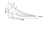
他の形態7
図16は他の形態6の相互補給制御におけるインク量IC,ITの変化と時間との関係
を示す図である。
図16に示すように、相互補給制御の回数が所定回数N3,N4となるまでは、タンク
2とカートリッジ3両方のインク収容体内の液量IT,ICを一定量Zだけ残して補給制
御を行うようにし、相互補給制御の回数が所定回数N3,N4となったらその時の補給制
御においてタンク2,カートリッジ3両方のインク収容体内のインク量が空状態になるま
で絞り込み、補給するという制御を、行うようにしてもよい。あるいは、相互補給制御の
開始からの時間が図外のタイマーに設定した所定時間(t1,t2)に達するまでは、イ
ンクを補給する側のインク収容体内の液量を一定量Zだけ残して補給制御を終了するよう
にし、所定時間(t1,t2)に達したら、その時の補給制御においてインクを補給する
側のインク収容体内のインク量が空状態になるまで補給するという制御を、相互に繰り返
すようにしてもよい。即ち、制御手段11は、インク収容体間で液体を相互に補給し、こ
の補給回数が所定数に達する毎又は相互補給が所定時間に達する毎に、液体を補給する側
の液体収容部内の液体量が空状態になるまで補給する。この場合、相互補給動作に変化を
付けることができるので、インクの澱みや付着、インクの色成分の沈降を効果的に防止で
きる。また、相互補給制御の切り換えを速くでき、ヘッド4に対してもインクをより早く
供給できるので、ヘッド4でのインク消費が多い場合に有効である。検出手段として、イ
ンク収容体内の液量に応じて、アナログ信号を出力するレベルセンサSx,Syを用いた
ので、インクを補給する側のインク収容体内のインクが所定量まで減少したか否かの判定
をレベルセンサからの出力により正確に行える。なお、アナログ信号を出力するものであ
ればレベルセンサを用いることに限定されない。
Other form 7
FIG. 16 is a diagram showing the relationship between changes in the ink amounts IC and IT and time in the mutual replenishment control according to the sixth embodiment.
As shown in FIG. 16, until the number of mutual replenishment control reaches a predetermined number N3, N4, the replenishment control is performed with the liquid amounts IT and IC in the ink storage bodies of both the
他の形態8
また、流量センサQ1としてインク流量に相当するアナログ信号をパルス処理しないで
制御手段11に供給するようなタイプの双方向アナログ信号出力流量センサを用いて構成
してもよい。この場合、制御手段11には、上記アナログ信号と所定値(比較レベル)と
を比較して、比較結果にもとづいて、往路補給制御手段51と復路補給制御手段52とを
相互に制御するように構成する。
これによれば、上記所定量を「0」とすれば流量0のときにルートAとルートBとの切
換えが可能となる。また、この所定値を可変可能として、空状態にやや近い状態とするこ
とにより、若干のインクを残存させつつ、インクの相互補給が可能となる。
あるいは、上記所定値の一方のみを「0」とすることで、図15に示すようなタンク2
,カートリッジ3の片方のみ空状態とする制御も可能となる。
あるいは、他の形態5で説明したと同様にアナログ信号を用いることでインク総和量I
Kを検出,判定できる。
Other form 8
The flow rate sensor Q1 may be configured by using a bidirectional analog signal output flow rate sensor of a type that supplies an analog signal corresponding to the ink flow rate to the control means 11 without performing pulse processing. In this case, the control means 11 compares the analog signal with a predetermined value (comparison level), and controls the outward supply control means 51 and the return supply control means 52 based on the comparison result. Configure.
According to this, if the predetermined amount is set to “0”, it is possible to switch between the route A and the route B when the flow rate is zero. In addition, by making this predetermined value variable and setting it to a state somewhat close to the empty state, it is possible to mutually supply ink while leaving some ink remaining.
Alternatively, by setting only one of the predetermined values to “0”, the
Also, it is possible to control only one of the
Alternatively, in the same manner as described in the other embodiment 5, by using an analog signal, the total ink amount I
K can be detected and determined.
他の形態9
図17は他の形態9の相互補給制御におけるインク量の変化と流量センサの出力との関
係を示す図である。
図17に示すように、制御手段11が流量センサQ1からパルスPを入力してから、別
途図外のタイマーに設定した一定時間経過Txの絞り時間経過後に次の補給制御に移行す
るようにしても良い。図1のように、インク流路に流量センサQ1を1つだけ備えた構成
の場合、制御手段11が流量センサQ1からパルスP(パルスPa,Pb)を入力した時
点では、インクを補給する側のインク収容体内のインクがまだ空状態になっていないこと
もあり得るため、他の形態8では、ルートA,又は、ルートBの流量が0となってパルス
Pa又はパルスPbを発生し、制御手段11がこれを入力してから一定時間Txだけ絞り
込み動作を行ってから次の補給制御に移行する。このようにすれば、タンク2,カートリ
ッジ3の絞り効果を向上できるのでタンク又はカートリッジのインク収容体内の存在して
いたインクをより確実に押出して攪拌でき、インク攪拌効果を向上できる。また、空状態
を所定時間Tx保持できるので、この間に空絞りを確実に行えるので、インクの澱みの追
い出し、絞り効果が期待できる。
FIG. 17 is a diagram showing the relationship between the change in the ink amount and the output of the flow sensor in the mutual replenishment control of the
As shown in FIG. 17, after the control means 11 inputs the pulse P from the flow rate sensor Q1, it shifts to the next replenishment control after the elapse of a certain time period Tx set in a timer not shown in the figure. Also good. As shown in FIG. 1, when only one flow sensor Q1 is provided in the ink flow path, when the control means 11 inputs a pulse P (pulses Pa, Pb) from the flow sensor Q1, the ink replenishment side is provided. In other mode 8, the flow rate of the route A or the route B becomes 0 and the pulse Pa or the pulse Pb is generated to control the ink in the ink container. After the
他の形態10
図18は他の形態10のプリンタ装置の押圧手段を示す図である。
インク収容体として、非透過性、かつ、可撓性を有した材料により形成されたインク収
容容積可変の袋体を用いる場合、インク収容体に押圧力を加えてインクを主連通路5Aに
押し出す押圧手段として、図18に示すような、機械式鋏手段70A,70Bを用いても
よい。機械式鋏手段70A,70Bは、2本の棒体71,71が回転中心軸72を介して
互いに逆方向に所定角変動可能なように構成される。2本の棒体71,71の互いに対向
する自由端71a側と自由端71b側との間にタンク2、カートリッジ3のインク収容体
を挟み込むと共に、ばね73で連結される。2本の棒体71,71の互いに対向する一方
の他端71c側にはソレノイド74が設けられ、他方の他端71d側には磁性体75が設
けられる。よって、制御手段11で、タンク2に設けられた機械式鋏手段70Aのソレノ
イド74とカートリッジ3に設けられた機械式鋏手段70Bのソレノイド74とを相互に
オンオフすることによって、ルートAとルートBによる相互補給制御を実現できる。
Other form 10
FIG. 18 is a view showing a pressing means of a printer apparatus according to another embodiment 10.
In the case of using a non-permeable and flexible bag body made of a flexible material as the ink container, a pressure is applied to the ink container to push out the ink to the
他の形態11
図19は他の形態11のプリンタ装置を示す図である。一方のインク収容体、例えば、
タンク2からのみ主連通路5Aを介してヘッド4にインクを供給するよう構成するととも
に、タンク2とカートリッジ3とをヘッド4を経由しない副連通路5Bで直接的に連通さ
せ、主連通路5Aを介して印字制御を行い、副連通路5Bを介して相互補給制御を行う構
成とした。即ち、カートリッジ3、タンク2、ヘッド4をインク供給路としての主連通路
5Aとインク往復路としての副連通路5Bとで直列に繋げた構成とした。
他の形態11によれば、噴射停止時に相互補給制御を行なうことで、噴射停止時にのみ
インクを攪拌させることでき。長期に渡って印字動作が行われないような場合にも、定期
的にインクを攪拌できる。
FIG. 19 is a diagram showing a printer apparatus according to another
Ink is supplied to the
According to the
他の形態12
図20は他の形態12のプリンタ装置を示す図である。
図20に示すように、ヘッド4は、インク路21,41と連通可能なサブタンク80と
、サブタンク80と連通したインク室24と、インク室24と連通した圧力室25と、圧
力室25と連通したノズル28と、アクチュエータ30とを備えた構成としてもよい。こ
の構成によれば、サブタンク80を備えるので、ヘッド4でのインク貯留量を多くでき、
連続印刷可能時間を長くできる。
Other form 12
FIG. 20 is a diagram illustrating a printer apparatus according to another twelfth embodiment.
As shown in FIG. 20, the
The continuous printing time can be extended.
他の形態13
図21は他の形態13の相互補給制御におけるインク量の変化と時間との関係を示す図
である。
図19で説明した制御(他の形態11)において、図21に示すように基準値M1,M
2をインク使用の時間経過に伴って次第に小さくなるように設定しても良い。これによれ
ば、インクの噴射初期ではルートA,ルートBの相互切換えの頻度を増すことができ、イ
ンクの攪拌効果を増加できる。
FIG. 21 is a diagram showing the relationship between the change in the ink amount and time in the mutual supply control of the
In the control described in FIG. 19 (other form 11), as shown in FIG.
2 may be set so as to gradually decrease as the ink usage time elapses. According to this, the frequency of mutual switching between the route A and the route B can be increased at the initial stage of ink ejection, and the ink stirring effect can be increased.
他の形態14
また、一定(単位)時間F毎に、判断1と判断2とを設定回数N繰り返したか否か(パ
ルスPa,Pbを設定個数カウントしたか否か)の判定を行う判定タイミングであるが、
図22に示すようにこの判定を常にカートリッジ3が空状態(所定量)に達したとき(パ
ルスPa発生時)に行うことで、タンク2にはカートリッジ3からのインクが全量移され
ているので相互補給の停止は常にカートリッジ3のインクが全量タンク2に移された時点
で行われる。従って別途ステップS9,ステップS10でカートリッジ3からタンク2に
インクを移送する必要が無くなり、無駄な動作を省略できる。なお、判断1,判断2(パ
ルスPa,パルスPb)のカウントについては、判断1,判断2(パルスPa,Pb)の
発生タイミングと時間Tとの関係を図外のRAM等のメモリにあらかじめ記憶し、このR
AMにより、時間Tを遡って単位時間Fにおける判断1,判断2の発生タイミングの数(
パルスカウント数)をカウントして判定するように構成してもよい。
Other form 14
In addition, it is a determination timing for determining whether or not the
As shown in FIG. 22, this determination is always performed when the
By AM, the number of occurrence timings of
It may be configured to count and determine the pulse count number).
他の形態15
また、制御手段11が図23に示すようにタンク内インク量ITを示すアナログ信号I
Ta,カートリッジ内インク量ICを示すアナログ信号ICaを入力して処理する場合に
は、図23に示すようにいずれか一方の、アナログ信号ITaを、等分に時分割して得ら
れる時間G毎に積分して、積分値Sを得ることで、この積分値Sをインク総和量IKに比
例する値として取扱うことができる。この場合、時間Gは調整手段で必要に応じて広く又
は細かく設定可能にしても良い。
Further, as shown in FIG. 23, the control means 11 has an analog signal I indicating the ink amount IT in the tank.
When processing is performed by inputting the analog signal ICa indicating Ta and the ink amount IC in the cartridge, as shown in FIG. 23, every one of the analog signals ITa obtained by time-sharing the analog signal ITa equally. To obtain an integral value S, the integral value S can be handled as a value proportional to the total ink amount IK. In this case, the time G may be set broadly or finely as necessary by the adjusting means.
他の形態16
また、上記アナログ信号ICa又はアナログ信号ITaのピーク値Rを検出することに
よっても、液体の総和量IKを推定できる。なお、ピーク値(波高値)は、アナログ信号
ICa,アナログ信号ITaを微分回路で微分することで、容易に検出できる。
この場合、前のピーク値と後のピーク値の差分Bを求めて、累計していくことで、ある
いは、上記積分の実施形態15では、前の積分値Sと後の積分値Sとの差分を求めて、累
計して行くことで消費量を推定できるので、既知のカートリッジ3,タンク2内の既知の
全量のインク量より上記消費量を減算することで、インクの総和量IKを求めることがで
き、この総和量IKが設定インク残量Wに達するか否かを判定することで、相互補給の停
止制御が可能となる。また、パルスPa,Pbは、いずれか一方をカウントするようにし
てもインク総和量IKを判定できる。
あるいは、上記アナログ信号ITa,ICaに代えて、流量センサQにより検出された
主連通路5A内のルートA,ルートBを介して流れる液体の流量を示すアナログ信号(パ
ルス処理を行わない信号)の変化を検出するようにしても、インク総和量IKの大きさを
推定できる。
また、判断1,判断2についても、いずれか一方の発生回数を単位時間F毎にカウント
するようにしても、インク総和量IKの大きさを推定できる。
また、液体収容部内の液体量を推定する方法としては、これ等の液体の液面レベルを検
出するセンサSx,Sy以外に、液体収容部内に収容した可撓性バックが液体加圧時に収
縮するときの形状変化を検出するセンサを用いても、あるいは、液体量の変化に応じて変
化する可撓性バックの重量を検出する重量センサを用いてもよい。
また、相互補給動作中に、停電等、あるいは必要に応じて電源がオフされる場合もある
が、相互補給動作中、常にルートA又はルートB,パルスPa,Pb等のデータをRAM
等のメモリに記憶しておき、電源オン復旧時、上記記憶データをもとに、相互補給動作が
開始されるようにすれば、何等支障無く復旧動作を継続できる。
また、ポンプP1,P2で第1,第2液体収容部を加圧するとして説明したが、タンク
2,カートリッジ3が空状態となると第1,第2液体収容部内の空気圧が増し、ポンプP
1,P2を駆動するモータの負荷が増加するので、この時の負荷電流を検出するように構
成することによっても、第1,第2液体収容部が空状態となったことを判定できる。
また、上記の場合、第1,第2液体収容部が空状態となることで空気圧が増加した場合
、圧力センサでこの圧力の急上昇を検出することによっても、第1,第2液体収容部が空
状態となったことを判定できる。
Also, the total liquid amount IK can be estimated by detecting the peak value R of the analog signal ICa or the analog signal ITa. The peak value (peak value) can be easily detected by differentiating the analog signal ICa and the analog signal ITa with a differentiating circuit.
In this case, the difference B between the previous peak value and the subsequent peak value is obtained and accumulated, or in the above-described
Alternatively, instead of the analog signals ITa and ICa, analog signals (signals that are not subjected to pulse processing) indicating the flow rate of the liquid flowing through the route A and route B in the
In addition, regarding the
In addition to the sensors Sx and Sy that detect the liquid level of these liquids, the flexible bag housed in the liquid container shrinks when the liquid is pressurized. A sensor that detects a change in shape at the time may be used, or a weight sensor that detects the weight of a flexible bag that changes according to a change in the amount of liquid may be used.
Further, during the mutual supply operation, there may be a power failure or the like, or the power may be turned off as necessary. During the mutual supply operation, data such as route A or route B, pulses Pa and Pb are always stored in the RAM.
If the replenishment operation is started based on the stored data at the time of power-on recovery, the recovery operation can be continued without any trouble.
In addition, the pumps P1 and P2 have been described as pressurizing the first and second liquid storage units. However, when the
Since the load of the motor driving the first and second motors P2 increases, it can be determined that the first and second liquid storage portions are in an empty state also by detecting the load current at this time.
In the above case, when the air pressure increases due to the empty state of the first and second liquid storage units, the first and second liquid storage units are also detected by detecting a sudden increase in the pressure with a pressure sensor. It can be determined that it is empty.
他の形態17
図24に示すように、副連通路5Bが、ヘッド4内においてヘッド4の液体噴射吐出口
をバイパスするように形成された構成とする。
他の形態17によれば、噴射時の相互補給制御において、インクがヘッド4内の副連通
路5Bを経由することでインクの攪拌効果を得ることができる。
As shown in FIG. 24, the sub communication path 5 </ b> B is configured to bypass the liquid ejection / ejection port of the
According to the
他の形態18
図25;図26に示すように、タンク2とカートリッジ3とをインク往復移動用の副連
通路5Bで直接的に連通させ、副連通路5Bの中間部5Cとヘッド4とを連通路で連通さ
せた構成とした。言い換えれば、一端がヘッド4に連通したヘッド側連通路5Xの他端と
、一端がタンク2に繋がれてタンク2と連通したタンク側連通路21aの他端と、一端が
カートリッジ3に繋がれてカートリッジ3と連通したカートリッジ側連通路41aの他端
とが、互いに連通するように繋がれた構成とし、ヘッド側連通路5Xの他端部にヘッド側
連通路5Xを開閉する開閉弁V10を設け、タンク側連通路21a又はカートリッジ側連
通路41aのいずれかに流量センサQ2を設けた。
よって、ヘッド側連通路5Xが開閉弁V10により閉じられた場合のタンク側連通路2
1aとカートリッジ側連通路41aとによってインク攪拌のための相互補給動作用の副連
通路5Bが形成され、開閉弁V10が開けられた場合のタンク側連通路21aとヘッド側
連通路5Xとによって、タンク2とヘッド4とを連通させるタンク側主連通路21が構成
され、開閉弁V10が開けられた場合のカートリッジ側連通路41aとヘッド側連通路5
Xとによって、カートリッジ3とヘッド4とを連通させるカートリッジ側主連通路41が
構成される。
従って、噴射時には、タンク側主連通路21、又は、カートリッジ側連通路41aを経
由してインクがヘッド4に供給され、噴射停止時には、副連通路5Bを経由した相互補給
制御が行なわれて、インクが攪拌される。
タンク側主連通路21経由でタンク2からヘッド4にインクを供給する場合には、開閉
弁V4を閉じて、開閉弁V3、V10を開く。カートリッジ側主連通路41経由でカート
リッジ3からヘッド4にインクを供給する場合には、開閉弁V3を閉じて、開閉弁V4、
V10を開く。副連通路5Bを用いた相互補給制御時には、開閉弁V10を閉じて、開閉
弁V3、V4を開く。
最良の形態18によれば、最良の形態と同じ効果が得られる。また、開閉弁の個数を減
らすことができる。
FIG. 25; As shown in FIG. 26, the
Therefore, the tank
1a and the cartridge
A cartridge-side
Therefore, at the time of ejection, ink is supplied to the
When supplying ink from the
Open V10. At the time of mutual supply control using the
According to the
他の形態19
なお、図25のヘッド4に接続されたヘッド側連通路5Xに流量センサQ4より成る消
費量検出手段を設けても良い。これによれば、既知の全体量から流量センサQ4で求めら
れるインク消費量を減算した値を、液体の総和量として検出できる。
It should be noted that a consumption amount detecting means comprising a flow rate sensor Q4 may be provided in the head
他の形態20
図27に示すように、主連通路5Aに対して設けた並列通路5Yにより副連通路5Bを
形成してもよい。即ち、開閉弁V3と袋側主インク出入口部20との間のタンク側主連通
路21と、開閉弁V4と袋側主インク出入口部40との間のカートリッジ側主連通路41
とを並列通路5Yで繋ぐことによって、互いに連通されたタンク側主連通路21と並列通
路5Yとカートリッジ側主連通路41とにより形成された副連通路5Bを設けるようにし
てもよい。
他の形態20では、最良の形態と同じ効果が得られる。また、インク収容袋体に袋側副
インク出入口部20a,40aを設けなくともよいので、インク収容部(タンク2、カー
トリッジ3)の構成を容易とできる。
As shown in FIG. 27, the
May be provided by a
In the
上述した各形態において、流量センサQ1は、タンク側主連通路21及びカートリッジ
側主連通路41のうちのいずれか一方、又は、タンク側主連通路21及びカートリッジ側
主連通路41の両方に設ければよい。または、インクの残量を検出する残量検出センサを
、タンク2内及びカートリッジ3内のうち何れか一方、又は、タンク2内及びカートリッ
ジ3内の両方に設けても良い。または、タンク2及びカートリッジ3におけるインク収容
体とインク収容体内のインクを導出するインク出入口部とを連通する導出路に、流量セン
サQ1や残量検出センサを設けても良い。
また、タンク2,カートリッジ3の空状態とは、ポンプP1,P2で加圧しても補給で
きない状態を意味し、従ってタンク2,カートリッジ3内に多少のインク滴が残存してい
ても、空状態として取扱うことができる。従って、空状態又は空状態に近い状態も含む。
圧力室13,33を加圧する加圧ポンプと圧力室13,33を減圧する減圧ポンプとを
別々に設けてもよい。
攪拌板65は、図24に示すように、副連通路5B内に設けてもよい。即ち、攪拌板6
5は、副連通路5B及び主連通路5Aに設けなくとも良いが、攪拌効果を高めるためには
、副連通路5B及び主連通路5Aのうちの少なくとも一方に設けることが望ましい。
In each form mentioned above, flow sensor Q1 is provided in either one of tank side
Further, the empty state of the
A pressurizing pump that pressurizes the
As shown in FIG. 24, the stirring
5 may not be provided in the
上記実施例は、インクジェット式のプリンタ装置を例として説明したが、インク以外の
他の液体を噴射したり吐出したりする液体噴射装置と、その液体を収容した液体容器を採
用しても良い。微小量の液滴を吐出させる液体噴射ヘッド等を備える各種の液体噴射装置
に流用可能である。なお、液滴とは、上記液体噴射装置から吐出される液体の状態をいい
、粒状、涙状、糸状に尾を引くものも含むものとする。また、ここでいう液体とは、液体
噴射装置が噴射させることができるような材料であれば良い。例えば、物質が液相である
ときの状態のものであれば良く、粘性の高い又は低い液状態、ゾル、ゲル水、その他の無
機溶剤、有機溶剤、溶液、液状樹脂、液状金属(金属融液)のような流状態、また物質の
一状態としての液体のみならず、顔料や金属粒子などの固形物からなる機能材料の粒子が
溶媒に溶解、分散または混合されたものなどを含む。また、液体の代表的な例としては上
記実施例の形態で説明したようなインクや液晶等が挙げられる。ここで、インクとは上記
実施例で説明したような一般的な水性インクおよび油性インク並びにジェルインク、ホッ
トメルトインク等の各種液体組成物を包含するものとする。液体噴射装置の具体例として
は、例えば液晶ディスプレイ、EL(エレクトロルミネッセンス)ディスプレイ、面発光
ディスプレイ、カラーフィルタの製造などに用いられる電極材や色材などの材料を分散ま
たは溶解のかたちで含む液体を噴射する液体噴射装置、バイオチップ製造に用いられる生
体有機物を噴射する液体噴射装置、精密ピペットとして用いられ試料となる液体を噴射す
る液体噴射装置、捺染装置やマイクロディスペンサ等であってもよい。さらに、時計やカ
メラ等の精密機械にピンポイントで潤滑油を噴射する液体噴射装置、光通信素子等に用い
られる微小半球レンズ(光学レンズ)などを形成するために紫外線硬化樹脂等の透明樹脂
液を基板上に噴射する液体噴射装置、基板などをエッチングするために酸又はアルカリ等
のエッチング液を噴射する液体噴射装置を採用しても良い。そして、これらのうちいずれ
か一種の噴射装置に本発明を適用することができる。また、本発明は、第1,第2液体収
容部のいずれかの液体を補給する側の液体収容部内の液体が所定量に減少するまで補給す
るように制御するものであって、上記第1,第2液体収容部の少なくとも一方の液体量を
検出する検出手段又は上記連通路内の液体流量を検知する検出し、この検出結果にもとづ
き第1,第2液体収容部内の液体の総和量を判定することを特徴とする判定方法より成る
ことについても、必要な効果を奏するものである。また、インク停止制御を判定手段の判
定結果にもとづき行うとして説明したが、インク停止制御に代えて、インクエンド表示の
み行うようにしてもよい。又は、インク停止制御前あるいはインク停止制御後にこのイン
クエンド表示を行うようにしてもよい。
In the above embodiment, the ink jet printer apparatus has been described as an example. However, a liquid ejecting apparatus that ejects or discharges liquid other than ink and a liquid container that stores the liquid may be employed. The present invention can be used for various liquid ejecting apparatuses including a liquid ejecting head that ejects a minute amount of liquid droplets. In addition, a droplet means the state of the liquid discharged from the said liquid ejecting apparatus, and shall also include what pulls a tail in granular shape, tear shape, and thread shape. The liquid here may be any material that can be ejected by the liquid ejecting apparatus. For example, it may be in the state when the substance is in a liquid phase, and may be in a liquid state with high or low viscosity, sol, gel water, other inorganic solvents, organic solvents, solutions, liquid resins, liquid metals (metal melts) ) And a liquid as one state of the substance, as well as particles in which functional material particles made of solid materials such as pigments and metal particles are dissolved, dispersed or mixed in a solvent. In addition, typical examples of the liquid include ink and liquid crystal as described in the above embodiments. Here, the ink includes general liquid inks and oil-based inks as described in the above embodiments, and various liquid compositions such as gel inks and hot melt inks. As a specific example of the liquid ejecting apparatus, for example, a liquid containing a material such as an electrode material or a coloring material used for manufacturing a liquid crystal display, an EL (electroluminescence) display, a surface emitting display, a color filter, or the like in a dispersed or dissolved state. It may be a liquid ejecting apparatus for ejecting, a liquid ejecting apparatus for ejecting a bio-organic material used for biochip manufacturing, a liquid ejecting apparatus for ejecting a liquid as a sample used as a precision pipette, a textile printing apparatus, a microdispenser, or the like. In addition, transparent resin liquids such as UV curable resin to form liquid injection devices that pinpoint lubricant oil onto precision machines such as watches and cameras, and micro hemispherical lenses (optical lenses) used in optical communication elements. A liquid ejecting apparatus that ejects a liquid onto the substrate or a liquid ejecting apparatus that ejects an etching solution such as an acid or an alkali to etch the substrate may be employed. The present invention can be applied to any one of these injection devices. According to the present invention, control is performed so that the liquid in the liquid container on the side of replenishing one of the first and second liquid containers is replenished until the liquid is reduced to a predetermined amount. , Detecting means for detecting the amount of liquid in at least one of the second liquid storage parts or detecting the flow rate of liquid in the communication path, and based on the detection result, the total amount of liquid in the first and second liquid storage parts is determined. The necessity of the determination method characterized by the determination also has a necessary effect. In addition, the ink stop control is described as being performed based on the determination result of the determination unit, but instead of the ink stop control, only the ink end display may be performed. Alternatively, the ink end display may be performed before the ink stop control or after the ink stop control.
1 プリンタ装置、2 インクタンク(第1液体収容部)、
3 インクカートリッジ(第2液体収容部)、4 ヘッド、5A 主連通路、
5B 副連通路、11 制御手段、28 ノズル(液体噴射吐出口)、
65 攪拌板、V5a,V5b 副連通路開閉弁。
1 printer device, 2 ink tank (first liquid container),
3 ink cartridge (second liquid container), 4 heads, 5A main communication path,
5B Sub-communication path, 11 control means, 28 nozzles (liquid ejection / discharge port),
65 Stirring plate, V5a, V5b Sub-communication passage opening / closing valve.
Claims (4)
液体を大気に開放しない状態で収容する第1,第2の液体収容部と、
上記第1液体収容部と上記第2液体収容部とを上記ヘッドを介して連通させる主連通路と、
上記第1液体収容部と上記第2液体収容部とを上記ヘッドを介さないで連通させる副連通路と、
上記主連通路及び上記副連通路の備えられた開閉弁と、
制御手段と、を備え、
上記制御手段は、
上記開閉弁を制御して上記副連通路を連通させた状態で、上記副連通路を介して上記第1液体収容部より上記第2液体収容部に液体を補給する第1の液体補給制御と、上記副連通路を介して上記第2液体収容部より上記第1液体収容部に液体を補給する第2の液体補給制御とを交互に切換える相互補給動作と、
上記開閉弁を制御して上記主連通路を連通させた状態で、上記主連通路を介して上記第1液体収容部より上記第2液体収容部に液体を補給する第3の液体補給制御と、上記主連通路を介して上記第2液体収容部より上記第1液体収容部に液体を補給する第4の液体補給制御とを交互に切換える相互補給動作と、を行い、
上記主連通路を介した上記相互補給動作において、上記第1液体収容部および上記第2液体収容部に収容される前記液体の総和量が所定の値になった場合に上記相互補給動作を停止することを特徴とする液体噴射装置。 A head for ejecting liquid;
First and second liquid storage portions for storing the liquid without opening it to the atmosphere;
A main communication path for communicating the first liquid storage part and the second liquid storage part via the head;
A sub-communication path that communicates the first liquid container and the second liquid container without the head;
An on-off valve provided with the main communication passage and the sub communication passage;
Control means,
The control means includes
A first liquid replenishment control for replenishing liquid from the first liquid container to the second liquid container via the sub-communication path in a state where the on-off valve is controlled to communicate with the sub-communication path; A mutual replenishment operation for alternately switching between a second liquid replenishment control for replenishing the liquid from the second liquid reservoir to the first liquid reservoir via the sub-communication path;
Third liquid supply control for supplying liquid from the first liquid storage part to the second liquid storage part via the main communication path in a state where the on-off valve is controlled to communicate with the main communication path. And a mutual replenishment operation for alternately switching the fourth liquid replenishment control for replenishing the liquid from the second liquid reservoir to the first liquid reservoir via the main communication path,
In the cross-supply operation through the main communication passage, the upper Symbol mutual dispensing operation when the total amount of the liquid contained in the first liquid storage unit and the second liquid storage unit reaches a predetermined value A liquid ejecting apparatus that stops.
Priority Applications (1)
| Application Number | Priority Date | Filing Date | Title |
|---|---|---|---|
| JP2008307105A JP5446228B2 (en) | 2008-12-02 | 2008-12-02 | Liquid ejector |
Applications Claiming Priority (1)
| Application Number | Priority Date | Filing Date | Title |
|---|---|---|---|
| JP2008307105A JP5446228B2 (en) | 2008-12-02 | 2008-12-02 | Liquid ejector |
Publications (3)
| Publication Number | Publication Date |
|---|---|
| JP2010131757A JP2010131757A (en) | 2010-06-17 |
| JP2010131757A5 JP2010131757A5 (en) | 2012-01-26 |
| JP5446228B2 true JP5446228B2 (en) | 2014-03-19 |
Family
ID=42343598
Family Applications (1)
| Application Number | Title | Priority Date | Filing Date |
|---|---|---|---|
| JP2008307105A Active JP5446228B2 (en) | 2008-12-02 | 2008-12-02 | Liquid ejector |
Country Status (1)
| Country | Link |
|---|---|
| JP (1) | JP5446228B2 (en) |
Families Citing this family (7)
| Publication number | Priority date | Publication date | Assignee | Title |
|---|---|---|---|---|
| KR20120041011A (en) * | 2010-10-20 | 2012-04-30 | 삼성전기주식회사 | Apparatus and method for controlling ink circulation |
| JP5796428B2 (en) * | 2011-09-14 | 2015-10-21 | セイコーエプソン株式会社 | Liquid ejection device |
| JP5828389B2 (en) * | 2011-09-27 | 2015-12-02 | セイコーエプソン株式会社 | Liquid filling method and liquid discharge apparatus |
| WO2013132484A1 (en) * | 2012-03-04 | 2013-09-12 | Stratasys Ltd. | System and method for depositing liquids |
| JP5659179B2 (en) * | 2012-03-16 | 2015-01-28 | 東芝テック株式会社 | Image forming apparatus |
| JP6471480B2 (en) | 2014-12-03 | 2019-02-20 | セイコーエプソン株式会社 | Liquid ejector |
| JP6891481B2 (en) * | 2016-12-21 | 2021-06-18 | セイコーエプソン株式会社 | Liquid injection device |
Family Cites Families (2)
| Publication number | Priority date | Publication date | Assignee | Title |
|---|---|---|---|---|
| JP2002370374A (en) * | 2001-06-18 | 2002-12-24 | Canon Inc | Ink-jet printing apparatus, printing head and ink supplying method |
| JP4108725B1 (en) * | 2007-03-02 | 2008-06-25 | シャープ株式会社 | Recording apparatus and recording method |
-
2008
- 2008-12-02 JP JP2008307105A patent/JP5446228B2/en active Active
Also Published As
| Publication number | Publication date |
|---|---|
| JP2010131757A (en) | 2010-06-17 |
Similar Documents
| Publication | Publication Date | Title |
|---|---|---|
| JP5446228B2 (en) | Liquid ejector | |
| US8287064B2 (en) | Liquid ejecting apparatus | |
| US20100103233A1 (en) | Liquid ejecting apparatus | |
| US9956784B2 (en) | Liquid ejecting apparatus and liquid supply method | |
| JP6870491B2 (en) | Liquid injection system and computer program | |
| JP5245975B2 (en) | Liquid supply device and liquid ejection device | |
| JP2009166473A (en) | Liquid feeding device and liquid jetting apparatus | |
| JP2010201829A (en) | Liquid supply device and liquid-jet device | |
| US20180333959A1 (en) | Liquid supplying device, liquid ejecting apparatus, and liquid supplying method | |
| JP2010120375A (en) | Liquid ejecting apparatus | |
| CN108656745B (en) | Liquid ejecting apparatus and liquid ejecting method | |
| JP2010188590A (en) | Liquid feeding apparatus and liquid jetting apparatus | |
| JP2010105387A (en) | Liquid ejecting apparatus | |
| JP6809254B2 (en) | Liquid injection system and computer program | |
| US20090167795A1 (en) | Liquid supply unit, liquid ejecting apparatus, and liquid supplying method | |
| JP2013071296A (en) | Liquid filling method and liquid discharge device | |
| EP3566875B1 (en) | Liquid ejecting apparatus, liquid filling method, and air bubble discharging method | |
| JP5397086B2 (en) | Fluid ejection device | |
| JP2010105390A (en) | Liquid ejecting apparatus | |
| JP2010131880A (en) | Liquid holding member and liquid jetting apparatus | |
| JP2013256129A (en) | Fluid jetting device | |
| US11230115B2 (en) | Liquid ejecting apparatus and method of maintaining liquid ejecting apparatus | |
| JP2008012804A (en) | Liquid jetting apparatus, and liquid residual amount operation method | |
| JP2018008379A (en) | Liquid jetting device | |
| JP2010221538A (en) | Liquid supply mechanism and liquid ejection device |
Legal Events
| Date | Code | Title | Description |
|---|---|---|---|
| A521 | Written amendment |
Free format text: JAPANESE INTERMEDIATE CODE: A523 Effective date: 20111202 |
|
| A621 | Written request for application examination |
Free format text: JAPANESE INTERMEDIATE CODE: A621 Effective date: 20111202 |
|
| A977 | Report on retrieval |
Free format text: JAPANESE INTERMEDIATE CODE: A971007 Effective date: 20130130 |
|
| A131 | Notification of reasons for refusal |
Free format text: JAPANESE INTERMEDIATE CODE: A131 Effective date: 20130205 |
|
| A521 | Written amendment |
Free format text: JAPANESE INTERMEDIATE CODE: A523 Effective date: 20130326 |
|
| A131 | Notification of reasons for refusal |
Free format text: JAPANESE INTERMEDIATE CODE: A131 Effective date: 20130702 |
|
| A521 | Written amendment |
Free format text: JAPANESE INTERMEDIATE CODE: A523 Effective date: 20130827 |
|
| TRDD | Decision of grant or rejection written | ||
| A01 | Written decision to grant a patent or to grant a registration (utility model) |
Free format text: JAPANESE INTERMEDIATE CODE: A01 Effective date: 20131203 |
|
| A61 | First payment of annual fees (during grant procedure) |
Free format text: JAPANESE INTERMEDIATE CODE: A61 Effective date: 20131216 |
|
| R150 | Certificate of patent or registration of utility model |
Ref document number: 5446228 Country of ref document: JP Free format text: JAPANESE INTERMEDIATE CODE: R150 Free format text: JAPANESE INTERMEDIATE CODE: R150 |
|
| S531 | Written request for registration of change of domicile |
Free format text: JAPANESE INTERMEDIATE CODE: R313531 |
|
| R350 | Written notification of registration of transfer |
Free format text: JAPANESE INTERMEDIATE CODE: R350 |