EP2754911A1 - Hydraulic actuation device for actuating at least a friction clutch transmission and at least one gear actuator in a motor vehicle - Google Patents
Hydraulic actuation device for actuating at least a friction clutch transmission and at least one gear actuator in a motor vehicle Download PDFInfo
- Publication number
- EP2754911A1 EP2754911A1 EP13006057.7A EP13006057A EP2754911A1 EP 2754911 A1 EP2754911 A1 EP 2754911A1 EP 13006057 A EP13006057 A EP 13006057A EP 2754911 A1 EP2754911 A1 EP 2754911A1
- Authority
- EP
- European Patent Office
- Prior art keywords
- piston
- clutch
- actuator
- cylinder
- actuating
- Prior art date
- Legal status (The legal status is an assumption and is not a legal conclusion. Google has not performed a legal analysis and makes no representation as to the accuracy of the status listed.)
- Granted
Links
- 230000005540 biological transmission Effects 0.000 title claims description 30
- 230000002441 reversible effect Effects 0.000 claims abstract description 12
- 230000000903 blocking effect Effects 0.000 claims description 25
- 239000012530 fluid Substances 0.000 claims description 20
- 238000005086 pumping Methods 0.000 claims description 20
- 238000006073 displacement reaction Methods 0.000 description 10
- 238000007789 sealing Methods 0.000 description 9
- 230000008859 change Effects 0.000 description 5
- 238000010586 diagram Methods 0.000 description 5
- 210000002023 somite Anatomy 0.000 description 5
- 230000005291 magnetic effect Effects 0.000 description 4
- 238000000034 method Methods 0.000 description 4
- 241001136792 Alle Species 0.000 description 3
- 101100116570 Caenorhabditis elegans cup-2 gene Proteins 0.000 description 3
- 101100116572 Drosophila melanogaster Der-1 gene Proteins 0.000 description 3
- 230000008878 coupling Effects 0.000 description 3
- 238000010168 coupling process Methods 0.000 description 3
- 238000005859 coupling reaction Methods 0.000 description 3
- 230000004913 activation Effects 0.000 description 2
- 238000013461 design Methods 0.000 description 2
- 230000002093 peripheral effect Effects 0.000 description 2
- 230000036316 preload Effects 0.000 description 2
- 230000008569 process Effects 0.000 description 2
- 101000952234 Homo sapiens Sphingolipid delta(4)-desaturase DES1 Proteins 0.000 description 1
- 102100037416 Sphingolipid delta(4)-desaturase DES1 Human genes 0.000 description 1
- 238000013459 approach Methods 0.000 description 1
- 230000004888 barrier function Effects 0.000 description 1
- 230000003749 cleanliness Effects 0.000 description 1
- 238000004891 communication Methods 0.000 description 1
- 230000006835 compression Effects 0.000 description 1
- 238000007906 compression Methods 0.000 description 1
- 238000011161 development Methods 0.000 description 1
- 230000018109 developmental process Effects 0.000 description 1
- 230000002349 favourable effect Effects 0.000 description 1
- 210000003746 feather Anatomy 0.000 description 1
- 230000005294 ferromagnetic effect Effects 0.000 description 1
- 238000001914 filtration Methods 0.000 description 1
- 239000007788 liquid Substances 0.000 description 1
- 230000007935 neutral effect Effects 0.000 description 1
- 230000009467 reduction Effects 0.000 description 1
- 230000004044 response Effects 0.000 description 1
- 230000035945 sensitivity Effects 0.000 description 1
Images


Classifications
-
- F—MECHANICAL ENGINEERING; LIGHTING; HEATING; WEAPONS; BLASTING
- F16—ENGINEERING ELEMENTS AND UNITS; GENERAL MEASURES FOR PRODUCING AND MAINTAINING EFFECTIVE FUNCTIONING OF MACHINES OR INSTALLATIONS; THERMAL INSULATION IN GENERAL
- F16D—COUPLINGS FOR TRANSMITTING ROTATION; CLUTCHES; BRAKES
- F16D48/00—External control of clutches
- F16D48/02—Control by fluid pressure
-
- F—MECHANICAL ENGINEERING; LIGHTING; HEATING; WEAPONS; BLASTING
- F16—ENGINEERING ELEMENTS AND UNITS; GENERAL MEASURES FOR PRODUCING AND MAINTAINING EFFECTIVE FUNCTIONING OF MACHINES OR INSTALLATIONS; THERMAL INSULATION IN GENERAL
- F16H—GEARING
- F16H61/00—Control functions within control units of change-speed- or reversing-gearings for conveying rotary motion ; Control of exclusively fluid gearing, friction gearing, gearings with endless flexible members or other particular types of gearing
- F16H61/0003—Arrangement or mounting of elements of the control apparatus, e.g. valve assemblies or snapfittings of valves; Arrangements of the control unit on or in the transmission gearbox
- F16H61/0009—Hydraulic control units for transmission control, e.g. assembly of valve plates or valve units
-
- F—MECHANICAL ENGINEERING; LIGHTING; HEATING; WEAPONS; BLASTING
- F16—ENGINEERING ELEMENTS AND UNITS; GENERAL MEASURES FOR PRODUCING AND MAINTAINING EFFECTIVE FUNCTIONING OF MACHINES OR INSTALLATIONS; THERMAL INSULATION IN GENERAL
- F16D—COUPLINGS FOR TRANSMITTING ROTATION; CLUTCHES; BRAKES
- F16D48/00—External control of clutches
- F16D48/02—Control by fluid pressure
- F16D48/04—Control by fluid pressure providing power assistance
-
- F—MECHANICAL ENGINEERING; LIGHTING; HEATING; WEAPONS; BLASTING
- F16—ENGINEERING ELEMENTS AND UNITS; GENERAL MEASURES FOR PRODUCING AND MAINTAINING EFFECTIVE FUNCTIONING OF MACHINES OR INSTALLATIONS; THERMAL INSULATION IN GENERAL
- F16H—GEARING
- F16H61/00—Control functions within control units of change-speed- or reversing-gearings for conveying rotary motion ; Control of exclusively fluid gearing, friction gearing, gearings with endless flexible members or other particular types of gearing
- F16H61/0021—Generation or control of line pressure
- F16H61/0025—Supply of control fluid; Pumps therefore
- F16H61/0031—Supply of control fluid; Pumps therefore using auxiliary pumps, e.g. pump driven by a different power source than the engine
-
- F—MECHANICAL ENGINEERING; LIGHTING; HEATING; WEAPONS; BLASTING
- F16—ENGINEERING ELEMENTS AND UNITS; GENERAL MEASURES FOR PRODUCING AND MAINTAINING EFFECTIVE FUNCTIONING OF MACHINES OR INSTALLATIONS; THERMAL INSULATION IN GENERAL
- F16H—GEARING
- F16H61/00—Control functions within control units of change-speed- or reversing-gearings for conveying rotary motion ; Control of exclusively fluid gearing, friction gearing, gearings with endless flexible members or other particular types of gearing
- F16H61/02—Control functions within control units of change-speed- or reversing-gearings for conveying rotary motion ; Control of exclusively fluid gearing, friction gearing, gearings with endless flexible members or other particular types of gearing characterised by the signals used
- F16H61/0262—Control functions within control units of change-speed- or reversing-gearings for conveying rotary motion ; Control of exclusively fluid gearing, friction gearing, gearings with endless flexible members or other particular types of gearing characterised by the signals used the signals being hydraulic
- F16H61/0265—Control functions within control units of change-speed- or reversing-gearings for conveying rotary motion ; Control of exclusively fluid gearing, friction gearing, gearings with endless flexible members or other particular types of gearing characterised by the signals used the signals being hydraulic for gearshift control, e.g. control functions for performing shifting or generation of shift signals
- F16H61/0267—Layout of hydraulic control circuits, e.g. arrangement of valves
-
- F—MECHANICAL ENGINEERING; LIGHTING; HEATING; WEAPONS; BLASTING
- F16—ENGINEERING ELEMENTS AND UNITS; GENERAL MEASURES FOR PRODUCING AND MAINTAINING EFFECTIVE FUNCTIONING OF MACHINES OR INSTALLATIONS; THERMAL INSULATION IN GENERAL
- F16H—GEARING
- F16H61/00—Control functions within control units of change-speed- or reversing-gearings for conveying rotary motion ; Control of exclusively fluid gearing, friction gearing, gearings with endless flexible members or other particular types of gearing
- F16H61/26—Generation or transmission of movements for final actuating mechanisms
- F16H61/28—Generation or transmission of movements for final actuating mechanisms with at least one movement of the final actuating mechanism being caused by a non-mechanical force, e.g. power-assisted
- F16H61/2807—Generation or transmission of movements for final actuating mechanisms with at least one movement of the final actuating mechanism being caused by a non-mechanical force, e.g. power-assisted using electric control signals for shift actuators, e.g. electro-hydraulic control therefor
-
- F—MECHANICAL ENGINEERING; LIGHTING; HEATING; WEAPONS; BLASTING
- F16—ENGINEERING ELEMENTS AND UNITS; GENERAL MEASURES FOR PRODUCING AND MAINTAINING EFFECTIVE FUNCTIONING OF MACHINES OR INSTALLATIONS; THERMAL INSULATION IN GENERAL
- F16H—GEARING
- F16H61/00—Control functions within control units of change-speed- or reversing-gearings for conveying rotary motion ; Control of exclusively fluid gearing, friction gearing, gearings with endless flexible members or other particular types of gearing
- F16H61/26—Generation or transmission of movements for final actuating mechanisms
- F16H61/28—Generation or transmission of movements for final actuating mechanisms with at least one movement of the final actuating mechanism being caused by a non-mechanical force, e.g. power-assisted
- F16H61/30—Hydraulic or pneumatic motors or related fluid control means therefor
-
- F—MECHANICAL ENGINEERING; LIGHTING; HEATING; WEAPONS; BLASTING
- F16—ENGINEERING ELEMENTS AND UNITS; GENERAL MEASURES FOR PRODUCING AND MAINTAINING EFFECTIVE FUNCTIONING OF MACHINES OR INSTALLATIONS; THERMAL INSULATION IN GENERAL
- F16H—GEARING
- F16H61/00—Control functions within control units of change-speed- or reversing-gearings for conveying rotary motion ; Control of exclusively fluid gearing, friction gearing, gearings with endless flexible members or other particular types of gearing
- F16H61/68—Control functions within control units of change-speed- or reversing-gearings for conveying rotary motion ; Control of exclusively fluid gearing, friction gearing, gearings with endless flexible members or other particular types of gearing specially adapted for stepped gearings
- F16H61/684—Control functions within control units of change-speed- or reversing-gearings for conveying rotary motion ; Control of exclusively fluid gearing, friction gearing, gearings with endless flexible members or other particular types of gearing specially adapted for stepped gearings without interruption of drive
- F16H61/688—Control functions within control units of change-speed- or reversing-gearings for conveying rotary motion ; Control of exclusively fluid gearing, friction gearing, gearings with endless flexible members or other particular types of gearing specially adapted for stepped gearings without interruption of drive with two inputs, e.g. selection of one of two torque-flow paths by clutches
-
- F—MECHANICAL ENGINEERING; LIGHTING; HEATING; WEAPONS; BLASTING
- F16—ENGINEERING ELEMENTS AND UNITS; GENERAL MEASURES FOR PRODUCING AND MAINTAINING EFFECTIVE FUNCTIONING OF MACHINES OR INSTALLATIONS; THERMAL INSULATION IN GENERAL
- F16D—COUPLINGS FOR TRANSMITTING ROTATION; CLUTCHES; BRAKES
- F16D48/00—External control of clutches
- F16D48/02—Control by fluid pressure
- F16D2048/0212—Details of pistons for master or slave cylinders especially adapted for fluid control
-
- F—MECHANICAL ENGINEERING; LIGHTING; HEATING; WEAPONS; BLASTING
- F16—ENGINEERING ELEMENTS AND UNITS; GENERAL MEASURES FOR PRODUCING AND MAINTAINING EFFECTIVE FUNCTIONING OF MACHINES OR INSTALLATIONS; THERMAL INSULATION IN GENERAL
- F16D—COUPLINGS FOR TRANSMITTING ROTATION; CLUTCHES; BRAKES
- F16D48/00—External control of clutches
- F16D48/02—Control by fluid pressure
- F16D2048/0227—Source of pressure producing the clutch engagement or disengagement action within a circuit; Means for initiating command action in power assisted devices
- F16D2048/0233—Source of pressure producing the clutch engagement or disengagement action within a circuit; Means for initiating command action in power assisted devices by rotary pump actuation
- F16D2048/0245—Electrically driven rotary pumps
- F16D2048/0248—Reversible rotary pumps, i.e. pumps that can be rotated in the two directions
-
- F—MECHANICAL ENGINEERING; LIGHTING; HEATING; WEAPONS; BLASTING
- F16—ENGINEERING ELEMENTS AND UNITS; GENERAL MEASURES FOR PRODUCING AND MAINTAINING EFFECTIVE FUNCTIONING OF MACHINES OR INSTALLATIONS; THERMAL INSULATION IN GENERAL
- F16H—GEARING
- F16H61/00—Control functions within control units of change-speed- or reversing-gearings for conveying rotary motion ; Control of exclusively fluid gearing, friction gearing, gearings with endless flexible members or other particular types of gearing
- F16H61/26—Generation or transmission of movements for final actuating mechanisms
- F16H61/28—Generation or transmission of movements for final actuating mechanisms with at least one movement of the final actuating mechanism being caused by a non-mechanical force, e.g. power-assisted
- F16H61/30—Hydraulic or pneumatic motors or related fluid control means therefor
- F16H2061/301—Hydraulic or pneumatic motors or related fluid control means therefor for power assistance, i.e. servos with follow up action
-
- F—MECHANICAL ENGINEERING; LIGHTING; HEATING; WEAPONS; BLASTING
- F16—ENGINEERING ELEMENTS AND UNITS; GENERAL MEASURES FOR PRODUCING AND MAINTAINING EFFECTIVE FUNCTIONING OF MACHINES OR INSTALLATIONS; THERMAL INSULATION IN GENERAL
- F16H—GEARING
- F16H2312/00—Driving activities
- F16H2312/14—Going to, or coming from standby operation, e.g. for engine start-stop operation at traffic lights
Definitions
- the present invention relates to a hydraulic actuator for actuating at least one friction clutch and at least one transmission actuator in a motor vehicle, according to the preamble of claim 1.
- Such actuators are used in bulk in modern motor vehicles when it comes to automated manual transmissions (ASG).
- Transmission actuators such as shift forks and shift sleeves, with or without synchronizer, and (dry or wet) friction clutches as flexible as possible and low friction and with little space requirement to operate.
- the actuating device has a power unit for generating a hydraulic pressure by means of a pump which can be driven by an electric pump drive to displace hydraulic fluid in a pumping direction, thereby charging a pressure accumulator separated from the pump via a check valve.
- the slide valves used have a significant leakage, which leads over a corresponding lifetime to a complete discharge of the pressure accumulator, which has a delay of the first operation to the loading time of the pressure accumulator result. Even when driving without a gear change, for example on the highway, therefore, a reloading of the pressure accumulator is required at regular intervals, which is also energetically unfavorable.
- the invention has for its object to provide for the actuation of at least one friction actuator and at least one transmission actuator in a motor vehicle, a hydraulic actuator which avoids the above disadvantages and over the described prior art above all has a significantly improved overall efficiency at a lower cost.
- a hydraulic actuator for the operation of at least one friction clutch and at least one transmission actuator in a motor vehicle, in addition to a power unit for generating a hydraulic pressure by means of a pump which is driven by an electric pump drive to move hydraulic fluid in a pumping direction, a Transmission section with a hydraulically connected to the power unit Geretellzylinder for the transmission actuator, a Kupplungsbetuschistsabterrorism with a hydraulically connected to the power unit Kupplungsstellzylinder whose piston is operatively connected to the friction clutch, and a control device that electrically connected to the pump drive and control members for the Gereteriosestellabites and the Kupplungsbetuschistor, and a control device that electrically connected to the pump drive and control members for the Getriebestellabites and the Kupplungsbetuschistor connected is; the piston of the clutch actuating cylinder, which is acted upon hydraulically on opposite sides, as a control member, a locking device with a blocking element functionally associated, which in a movement of the
- the coordination of pump drive and actuator can be done via the control unit so that first the actuator of the locking device is electrically controlled to bring the locking element from its movement of the piston of the clutch actuator normally preventing blocking position in its release position, so that by the Rastier owned caused latching or blocking of the piston is released. Then, the controller electrically controls the pump drive to start the reversing pump with the desired pumping direction, whereupon the hydraulic pressure acting on the corresponding side of the piston of the clutch actuator generates movement of the piston in a predetermined direction to actuate the friction clutch operatively connected thereto.
- the piston As soon as the piston has reached the desired position - which can be detected, for example, via a displacement sensor on the clutch actuating cylinder - the energization of the actuator of the locking device is terminated by the control device and the pump drive is switched off. Then the locking element returns due to the spring bias in its movement of the piston preventing locking position.
- the pump drive and the actuator of the latching device can also be operated in a coordinated manner by means of the control device such that the actuator is initially electrically actuated is to cancel the locking of the piston of the Kupplungsstellzylinders by retracting the locking element, then the pump is operated with a defined pumping direction to initiate a movement of the piston in a predetermined direction, and shortly thereafter, the actuator is de-energized, so that the spring-biased locking element automatically gets into its blocking position / latching takes place as soon as this is possible again due to the relative position of the components involved (blocking element / piston), whereupon the pump is turned off. Any sensing of the piston position or the like. is not necessary with this alternative.
- the proposed hydraulic actuator operates at very low cost in terms of energy, and thus already low cost, especially when operating the friction clutch, because energization of the electrical components must be made only if and only if or engagement of the friction clutch an actuating movement of the piston of the clutch actuating cylinder is required, which is otherwise prevented by the locking element of the locking device from moving. Any charge in the power unit or spool valves - and thus an increased oil purity - are just as little necessary as a "under-pressure-holding" of the clutch actuator cylinder. In addition, because always two elements - pump drive and actuator of the locking device - must be controlled to initiate a movement, finally, the security against incorrect operations is finally increased.
- the locking device in principle, it is possible to provide the locking device on a component which is connected to produce the operative connection to the friction clutch on the piston of the clutch actuating cylinder, such as a piston rod.
- the locking device is mounted on the clutch actuator cylinder, that the locking element cooperates with locking portions on the piston of the clutch actuating cylinder to hold the piston in a rest position or an actuating position or release from the respective position - thus not only a functional but also a spatial Assigning the locking device is given to the piston of the clutch adjusting cylinder.
- the locking portions on the piston of the clutch adjusting cylinder can be formed on the piston circumference in a simple manner by axially spaced-apart recesses - possibly also in the form of circumferential radial grooves.
- the piston of the clutch actuator cylinder can be operatively connected on two opposite sides, each with a friction clutch, so that either one friction clutch or the other friction clutch can be actuated by means of only one clutch actuator cylinder ,
- the clutch actuating cylinder can have a sensor device for detecting the position of the piston, preferably with a sensor arranged on the cylinder housing and a signal element attached to the piston.
- the electrically controllable actuator is an electromagnetic actuator, as they are inexpensive and readily available commercially. Since the electrical control of the actuator always takes place only for a short time, namely when an actuation movement of the piston of the clutch actuator cylinder is desired, the energy balance is favorable.
- the hydraulic active connection can be influenced or controlled, this is advantageous for the sensitivity of the disengagement and, in particular, engagement of the friction clutch - in particular when the latter is a wet friction clutch, which as a rule has only a very small activation travel has.
- the actuating device may be designed such that the clutch master cylinder in a conventional manner associated with a reservoir for hydraulic fluid, starting from the clutch master cylinder in the pressure line between the clutch master cylinder and the clutch slave cylinder in the direction of the clutch master cylinder locking check valve and an electromagnetically actuated, via a Drain line connected to the expansion tank proportional throttle valve (which can be biased in principle in zero passage position or reverse zero position) are connected by means of which the hydraulic pressure in the clutch slave cylinder is defined adjustable.
- the proportional throttle valve can be so be formed that it is in the non-activated state in zero-passage position, so that no current can be established without energization of the proportional throttle valve in the clutch slave cylinder. Since in each case two elements (pump drive and proportional throttle valve) must be controlled in order to initiate an actuating movement on the clutch slave cylinder, the security against incorrect operations is significantly increased.
- a pressure accumulator in the pressure line between the Check valve and the proportional throttle valve is hydraulically connected via a non-actuated state blocking switching valve with the drain line.
- the numeral 10 generally indicates a hydraulic actuator for actuating one (or more) friction clutch (s) C and at least one transmission actuator - in the illustrated embodiment, four transmission actuators F1 for an automated manual transmission (ASG) having seven forward gears G1 to G7 and one reverse gear GR to F4 with dashed lines shown schematically as shift rails with shift forks - in a motor vehicle.
- the actuator 10 may be roughly divided into three hydraulic sections (each framed by dotted lines).
- control unit ECU which is electrically connected to the pump drive M and to be explained in more detail for the Gereteriosestellabites 16 and the clutch actuating portion 18 (starting from the control unit ECU with dashed lines to the sides and down) and in turn of a Parent transmission control unit (not shown) is driven (dashed line above the ECU ECU).
- a piston 20 of the Kupplungsstellzylinders CC which is acted upon hydraulically on opposite sides 22, 24 (double-acting piston-cylinder arrangement), as a control element a locking device 26 with a blocking element 28 functional - and in the illustrated embodiment, also spatially - Is assigned, which is spring-biased by means of a spring 30, for example a helical compression spring in a movement of the piston 20 preventing locking position and which by means of an electrically controllable via the control unit ECU, preferably electromagnetic actuator 32 from the locking position against the spring preload in a movement of the Piston 20 permitting or enabling release position can be moved.
- a spring 30 for example a helical compression spring in a movement of the piston 20 preventing locking position
- an electrically controllable via the control unit ECU preferably electromagnetic actuator 32 from the locking position against the spring preload in a movement of the Piston 20 permitting or enabling release position can be moved.
- the pumping direction R of the pump P is reversible (in Fig. 1 indicated by a double arrow; so-called reversible pump) to the piston 20 of the clutch actuator CC for an actuation movement depending on the pumping direction R on its one (left active surface) or its other (right working surface) side 22, 24 hydraulically act, the control unit ECU, the electrical control of pump drive M and actuator 32 suitably coordinated to off the friction clutch C as required or engage (explained in more detail below).
- the pump P of the power unit 12 has two hydraulic ports 34, 36, of which, depending on the selected or by the control unit ECU predetermined pumping direction R of a connection to the pump inlet (suction port), via which the hydraulic fluid is sucked or sucked, and the other port forms the pump outlet (pressure port) through which the hydraulic fluid is delivered with pressure.
- Suitable pump types are, for example, gear pumps, roller cell pumps, vane pumps and radial or axial piston pumps.
- the pump P is designed as a fixed displacement pump, which supplies a constant volume flow for a predetermined speed of the pump drive M. Possibly.
- the pump drive M can be controllable in rotational speed in order to be able to influence the setting speed of the clutch actuator cylinder CC, for example.
- the energization or control of the pump drive M via the in Fig. 1 Dashed power cable, which is electrically connected to the control unit ECU.
- Each hydraulic port 34, 36 of the pump P is connected to the reservoir 14 via a suction line 38, 40, in which a blocking in the direction of the reservoir 14 check valve 42, 44 is connected.
- the check valves 42, 44 may be biased in their blocking in the direction of the reservoir 14 position; this is not shown in the figures.
- a branching pressure line 46, 48 is connected, which provides for a hydraulic connection of the power unit 12 to the Kupplungsstellzylinder CC and the Getriebestellzylindern GC1 to GC4, all parallel with respect to the pump P. are switched.
- a branching pressure line 46, 48 is connected, which provides for a hydraulic connection of the power unit 12 to the Kupplungsstellzylinder CC and the Getriebestellzylindern GC1 to GC4, all parallel with respect to the pump P. are switched.
- the pump P via the hydraulic port 34 hydraulic fluid from the pressure line 46 and possibly via the check valve 42 and the suction line 38 sucks from the reservoir 14.
- the pump P conveys the hydraulic fluid under pressure into the pressure line 48.
- the check valve 44 prevents a pressure reduction or a return flow of the hydraulic fluid to the reservoir 14.
- the pressure line 48 is depressurized while the pressure line 46 is pressurized is when the pump P with a pumping direction R counterclockwise in Fig. 1 works, with hydraulic fluid in Fig. 1 is moved from the right of the pump P to the left of the pump P or moved.
- the pressure lines 46, 48 lead in accordance with Fig. 2 each to a control or pressure port 50, 52 of the clutch actuator cylinder CC.
- the pressure ports 50, 52 are in Fig. 2 schematically illustrated as channels in a cylinder housing 54 of the clutch actuator CC, which forms a cylinder chamber 56 of the clutch actuator CC, in which the piston 20 two pressure chambers 58, 60 separated from each other.
- the piston 20 at its two ends on the outer circumference side, each with a sealing element 62, 64 - for example, a known groove ring - provided, which cooperates with the inner peripheral surface of the cylinder housing 54 to seal the respective pressure chamber 58 and 60 dynamically.
- a plurality, here two locking portions are formed on the piston 20, with which the locking element 28 of the illustrated embodiment on the clutch actuator CC, more precisely its cylinder housing 54 attached locking device 26 cooperates, around to hold the piston 20 in a rest position (as shown) or an actuating position or release from the respective position, as will be described in more detail below.
- the piston-side locking sections are axially spaced-apart recesses 66, 68, which are formed on the circumference of the piston 20.
- the locking device 26 has a housing 70, which is fastened in the illustrated embodiment in a suitable manner on the outer circumference of the cylinder housing 54 of the clutch actuator CC.
- a magnet coil 72 of the actuator 32 housed in the housing 70 is a magnet coil 72 of the actuator 32, which surrounds the here acting as armature of a magnetic drive, ferromagnetic locking element 28 at least partially concentric.
- the in the magnetic coil 72 piston-like displaceable locking element 28 passes through an opening 74 in the housing 70, so that a on in Fig. 2 lower end of the locking element 28 provided, to its free end in cross-section slightly tapered Rastiervorsprung 76 with the recess 66 or 68 in the piston 20 can engage.
- the locking element 28 is elastically supported by the spring 30 against a bottom portion 78 of the housing 70.
- the energization of the solenoid 72 finally takes place via the in Fig. 1 dashed power cable, which is electrically connected to the ECU.
- the spring 30 strives to push the locking element 28 out of the housing 70 of the locking device 26, so that in the de-energized state of the solenoid 72 of the Rastiervorsprung 76 due to the force of the spring 30 with one of the recesses 66, 68 on the piston 20th is kept in engagement.
- positive connection of the piston 20 is prevented even when pressurizing one of the pressure chambers 58, 60 from, in the clutch actuator CC to move.
- the magnetic coil 72 when the magnetic coil 72 is energized, the resulting magnetic force pulls the blocking element 28 against the force of the spring 30 into the housing 70 in a direction substantially perpendicular to the direction of displacement of the piston 20, the locking projection 76 protruding from the respective recess 66 or 68 is released.
- the piston 20 can now by pressurizing the corresponding pressure chamber 58 or 60 in Fig. 2 be moved to the left or right.
- the respective position of the latching device 26 (open or latched), i. of the locking element 28 with respect to the housing 70 of the latching device 26 can be determined indirectly by means of the control unit ECU via the inductance of the actuator 32, which in a movement of the locking element 28 relative to the housing 70 in accordance with the current air gap, so the clear distance between the blocking element 28 and the bottom portion 78 of the housing 70 in the region of the spring 30 changes.
- a piston rod 80 which extends in a suitably sealed manner (not shown in detail) through a wall 82 of the cylinder housing 54 of the Kupplungsstellzylinders CC and is operatively connected to an adjacently arranged clutch master cylinder CM, more precisely with the Master piston 84 is mechanically coupled.
- the trained in known manner clutch master cylinder CM has a cylinder housing 86 in which the master piston 84 is received longitudinally displaceable and limits a pressure chamber 88.
- the master piston 84 is provided on the outer circumference with a primary sealing element 90 and a secondary sealing element 92, which dynamically seal against an inner circumferential surface of the cylinder housing 86 and define a trailing region 94 between them.
- the pressure chamber 88 is connected without pressure to the wake region 94 via a follower connection 96, which is in fluid communication via an overflow connection 98 with a surge tank 100.
- the primary sealing element 90 passes over the follower connection 96, so that the pressure chamber 88 and the trailing region 94 are hydraulically separated from one another and a hydraulic pressure builds up in the pressure chamber 88. Hydraulic fluid can now be displaced from the pressure chamber 88 into a pressure line 104 connected to the pressure port 102 via a pressure port 102 of the clutch master cylinder CM.
- Fig. 1 how further the Fig. 1 can be seen is the clutch master cylinder CM via the pressure line 104 hydraulically connected to a clutch slave cylinder CS, which may be a classic slave cylinder or a so-called.
- the clutch slave cylinder CS has in a conventional manner a longitudinally displaceably received in a cylinder housing 106, against an inner peripheral surface of the cylinder housing 106 suitably dynamically sealed slave piston 108 which limits on one side via the pressure line 104 hydraulically acted upon pressure chamber 110 and on its other side at 112th is mechanically connected to the friction clutch C.
- the clutch actuator CC in the illustrated embodiment, equipped with a sensor device 114 for detecting the position of the piston 20 having a cylinder housing 54 arranged on the sensor 116 (eg, a Hall sensor) and a signal attached to the piston 20 118 (eg Permanent magnet).
- the sensor device 114 is also electrically connected to the control unit ECU (in FIG Fig. 1 indicated by dashed line), which processes the position signals, approximately to determine the respective operating state of the Kupplungsstellzylinders CC and / or the latching device 26 in response to the position of the piston 20 to control.
- the clutch slave cylinder CS may be provided with a sensor 120 electrically connected to the control unit for the stroke of the slave piston 108, as in Fig. 1 shown.
- gearbox section 16 with its four double-acting gearbox cylinders GC1 to GC4 connected to the pressure lines 46,48 in parallel hydraulic pump P
- the individual gearbox cylinders GC1 to GC4 are the same as those shown in FIG Fig. 1 already suspect - the clutch actuator CC are very similar.
- sensed actuating cylinders whose pistons can either be fixed or released by means of a respectively assigned, spring-biased latching device which can be electromagnetically unlocked via the control unit ECU, in order, depending on the hydraulic actuation of the pistons in FIG Fig. 1 to be moved to the right or left.
- the pistons of the gear actuator cylinders GC1 to GC4 in the illustrated embodiment - unlike the clutch actuator CC according to Fig. 1 - Provided with three barrier recesses a1, b1, c1, a2, b2, c2, a3, b3, c3 and a4, b4, c4 respectively. While the blocking recesses b1 to b4 each define a rest or neutral position of the respective piston and of the transmission operating member F1 to F4 operatively connected thereto, the remaining blocking recesses a1 to a4 and c1 to c4 each ensure a specific switching position.
- a lock at a1 for an engaged forward gear G3, at a2 for an engaged reverse gear GR, at a3 for an engaged forward gear G6, at a4 for an engaged forward gear G5, at c1 for an engaged forward gear G1, at c2 for an engaged forward gear G2, at c3 for an engaged forward gear G4 and finally at c4 for an engaged forward gear G7.
- gear actuator cylinders are the older German patent application no. 10 2011 107 263.6 ( DE-A-10 2011 107 263 ) of the same applicant, which is hereby expressly incorporated herein by reference.
- the actuator 32 of the latching device 26 is first energized via the control unit ECU.
- the locking member 28 is magnetically withdrawn against the force of the spring 30, the Rastiervorsprung 76 of the respective, here the right recess 66 on the piston 20 is released, so that the detent is released.
- the pump drive M is energized via the control unit ECU in such a way that the pump P starts up with the pumping direction R required for the desired actuating movement direction, eg with a pumping direction R from the left of the pump P to the right of the pump P in FIG Fig. 1 (Pump turns clockwise). Consequently, there is a hydraulic loading of the pressure chamber 60 in the clutch actuator CC and thus a displacement of the piston 20 to the right in Fig. 1 , After a short travel of the piston 20, the energization of the actuator 32 can be turned off, so that the spring 30, the blocking element 28 in Fig. 1 tried to move down.
- an actuating movement is generated at the friction clutch C or a specific one of the transmission actuator members F1 to F4 can be moved by the ECU ECU by energizing the locking device 26 at which the friction clutch C and the respective transmission actuator F1 to F4 assigned Setting cylinder CC or GC1 to GC4 lifts the piston latching and the pump P in accordance with the desired direction of adjustment with certain pumping direction R turns on, while the pistons of the other actuating cylinder are kept de-energized via this functionally associated locking devices.
- the proportional throttle valve 124 is executed in the illustrated embodiment as electromagnetically actuated, in the non-activated state in zero-passage position switched 2/2 ball seat valve, as it is in principle from the DE-A-196 33 420 ( Fig. 4 ) of the same applicant, which is hereby incorporated by reference for further details on the valve.
- a throttle gap between the valve seat and valve body can be closed or variably adjusted, can run through the hydraulic fluid from the pressure line 104 into the drain line 126, so that due to the Check valve 122 "caged" pressure in the clutch slave cylinder Held CS or relieved in a defined manner to the expansion tank 100 down or can be reduced.
- the proportional throttle valve 124 in order to open or disengage the friction clutch C, the proportional throttle valve 124 must be energized to close the latter so that a pressure can build up in the clutch slave cylinder CS at all when the clutch master cylinder CM is operated by the clutch slave cylinder CC as described above.
- the pump P unlike the first embodiment; this can rather be done sensitively with suitable electrical control of the proportional throttle valve 124 for variable adjustment of the throttle gap.
- the clutch actuator CC must be brought back into its initial or idle state at the same time or thereafter, by canceling the latching of the piston 20 in the actuated position by energizing the latching device 26, moving the piston 20 by levorotatory operation of the pump P and finally locking the Piston 20 in the rest position by Entstromen the locking device 26th
- a check valve 122 and a proportional throttle valve 124 - here again an electromagnetically actuated 2/2 ball seat valve - connected in series.
- the latter is, however, unlike the second embodiment, in the non-activated state in locking zero position, ie the valve body is spring-biased against the valve seat and must be electromagnetically effected against the spring force lifted from the valve seat to set the throttle gap defined.
- the proportional throttle valve 124 is arranged so that it acts like a spring-biased non-energized in the direction of the clutch master cylinder CM non-return valve.
- an accumulator 128 is connected in the pressure line 104, which also between the check valve 122 and the proportional throttle valve 124 via an electromagnetically actuated, in the non-actuated state spring biased blocking switching valve 130 with the drain line 126 hydraulically connected is.
- the pressure sensor 132 can also advantageously serve, in conjunction with the control unit ECU, to pre-bias the proportional throttle valve 124 in such a way that its opening point can be approached faster.
- the disengagement and engagement of the friction clutch C then takes place as follows: First, the latching device 26 is energized to fill the (spring) pressure accumulator 128 and the pump P is turned clockwise so that the clutch actuating cylinder CC actuates the clutch master cylinder CM.
- the spring preload on the proportional throttle valve 124 is in this case so high that the displaced as a result of the actuation of the clutch master cylinder CM volume of hydraulic fluid is pressed into the pressure accumulator 128; the check valve 122 and the blocking switching valve 130 hold the pressure.
- the pump P is operated counterclockwise until the piston 20 reaches its rest position.
- the clutch master cylinder CM sucks hydraulic fluid out of the expansion tank 100 via the overflow connection 98, so that it is ready for the next actuation. Possibly. For example, several such operations of the clutch master cylinder CM via the clutch actuator CC can be done until the pressure accumulator 128 is sufficiently filled. Subsequently, the locking device 26 is de-energized and locks the piston 20 of the Kupplungsstellzylinders CC; the pump P is switched off.
- the opening or disengaging the friction clutch C is then carried out solely by suitable energizing the proportional throttle valve 124, wherein the pressure accumulator 128 supplies the pressure required for the actuation of the clutch slave cylinder CS.
- the switching valve 130 is first energized to connect the pressure line 104 to the drain line 126.
- the proportional throttle valve 124 is suitably activated to hydraulically relieve the clutch slave cylinder CS in a defined manner, thereby effecting a path-controlled engagement movement.
- Fig. 5 shown fourth embodiment differs from the embodiments described above essentially by the fact that the piston 20 of the clutch actuator CC on two opposite sides 22, 24 each having a friction clutch C, C 'is operatively connected, so that by means of the clutch actuator CC optionally a friction clutch C that can be assigned in a dual-clutch transmission, for example, the even forward gears G2, G4 and G6 and the reverse gear GR, or the other friction clutch C ', which can be assigned in a dual-clutch transmission about the odd-numbered forward gears G1, G3, G5 and G7, operable ,
- the piston 20 of the clutch actuator cylinder CC mechanically coupled on both sides with a respective master piston 84, 84 'of a clutch master cylinder CM, CM'.
- the respective further operative connection to the friction clutch C or C ' is as in the second embodiment according to Fig. 3 trained, so that reference can be made to the above description.
- a further recess 67 is further provided on the piston 20, so that this has a total of three recesses 66, 67, 68.
- the middle recess 67 defines here the basic or rest position of the piston 20 in the clutch actuator CC, which in Fig. 5 right recess 66, the actuating position of the piston 20 upon actuation of a friction clutch C 'and the in Fig. 5 Left recess 68, the operating position of the piston 20 upon actuation of the other friction clutch C.
- the detent and displacement of the piston 20 is carried out as already described above.
- a hydraulic actuator for at least one friction clutch and at least one transmission actuator comprises a power unit for generating pressure by means of an electrically driven Pump, hydraulically connected Geretell- and Kupplungsbetuschistsabbalde with Geretell- and Kupplungsstellzylindern and an electrical control unit for controlling these modules.
- a piston of the clutch actuating cylinder which is operatively connected to the friction clutch and hydraulically acted upon on opposite sides, a locking device is associated with a locking element which is spring-biased in a piston movement preventing blocking position and which by means of an activatable via the control unit actuator from the blocking position into a Piston movement permitting release position is movable.
- a pumping direction of the pump is reversible, to act on the piston for an actuating movement depending on the pumping direction on one side or the other.
- the control unit coordinates the activation of the pump drive and actuator in order to disengage or engage the friction clutch.
Landscapes
- Engineering & Computer Science (AREA)
- General Engineering & Computer Science (AREA)
- Mechanical Engineering (AREA)
- Physics & Mathematics (AREA)
- Fluid Mechanics (AREA)
- Hydraulic Clutches, Magnetic Clutches, Fluid Clutches, And Fluid Joints (AREA)
Abstract
Description
Die vorliegende Erfindung bezieht sich auf eine hydraulische Betätigungsvorrichtung für die Betätigung wenigstens einer Reibkupplung und wenigstens eines Getriebestellglieds in einem Kraftfahrzeug, gemäß dem Oberbegriff des Patentanspruchs 1. Derartige Betätigungsvorrichtungen kommen in modernen Kraftfahrzeugen massenweise zum Einsatz, wenn es gilt, in automatisierten Schaltgetrieben (ASG), Doppel- oder Mehrkupplungsgetrieben (DKG) oder trennbaren Verteiler- und Differentialgetrieben Getriebestellglieder, wie Schaltgabeln und Schaltmuffen, mit oder ohne Synchronisiereinrichtung, und (Trocken- oder Nass-)Reibkupplungen möglichst flexibel und reibungsarm sowie mit geringem Bauraumbedarf zu betätigen.The present invention relates to a hydraulic actuator for actuating at least one friction clutch and at least one transmission actuator in a motor vehicle, according to the preamble of claim 1. Such actuators are used in bulk in modern motor vehicles when it comes to automated manual transmissions (ASG). , Double or multi-clutch transmissions (DKG) or separable distributor and differential gearboxes Transmission actuators, such as shift forks and shift sleeves, with or without synchronizer, and (dry or wet) friction clutches as flexible as possible and low friction and with little space requirement to operate.
Aus der den Oberbegriff des Patentanspruchs 1 bildenden
Zwar ist bei diesem Stand der Technik in vorteilhafter Weise nur eine Leistungseinheit vorgesehen, die sowohl den Getriebestellabschnitt als auch den Kupplungsbetätigungsabschnitt mit Hydraulikdruck versorgt. Ein Nachteil dieses Stands der Technik mit Druckspeicher in der Leistungseinheit wird jedoch darin gesehen, dass das Hydraulikfluid bei der Speicherladung auf ein Druckniveau weit oberhalb des insbesondere im Kupplungsbetätigungsabschnitt maximal benötigten Drucks gepumpt werden muss, um nach Entnahme der benötigten Menge noch den erforderlichen Arbeitsdruck bieten zu können, was energetisch ungünstig ist und den Wirkungsgrad der Vorrichtung beträchtlich mindert. Ferner erfordern die als Schieberventile ausgeführten elektromagnetisch betätigbaren Ventile - die den größten Kostenfaktor innerhalb dieser Betätigungsvorrichtung darstellen - aufgrund der engen Spalte eine hohe Ölreinheit und bedingen oftmals Filtermaßnahmen. Dennoch haben die verwendeten Schieberventile eine nicht unerhebliche Leckage, die über eine entsprechende Standzeit zu einer vollständigen Entladung des Druckspeichers führt, was eine Verzögerung der ersten Betätigung um die Ladezeit des Druckspeichers zur Folge hat. Auch beim Fahren ohne Gangwechsel, beispielsweise auf der Autobahn, ist daher ein Nachladen des Druckspeichers in regelmäßigen Zeitabständen erforderlich, was ebenfalls energetisch ungünstig ist.Although in this prior art, only one power unit is advantageously provided, which supplies both the Getriebestellabschnitt and the clutch actuating portion with hydraulic pressure. A disadvantage of this prior art with pressure accumulator in the power unit, however, is seen in the fact that the hydraulic fluid must be pumped at the storage charge to a pressure level far above the maximum required in particular in the clutch actuation pressure to provide after removal of the required amount nor the required working pressure can, which is energetically unfavorable and considerably reduces the efficiency of the device. Furthermore, designed as slide valves electromagnetically actuated valves - which represent the largest cost factor within this actuator - due to the narrow column high oil cleanliness and often require filtering measures. Nevertheless, the slide valves used have a significant leakage, which leads over a corresponding lifetime to a complete discharge of the pressure accumulator, which has a delay of the first operation to the loading time of the pressure accumulator result. Even when driving without a gear change, for example on the highway, therefore, a reloading of the pressure accumulator is required at regular intervals, which is also energetically unfavorable.
Der Erfindung liegt die Aufgabe zugrunde, für die Betätigung wenigstens einer Reibkupplung und wenigstens eines Getriebestellglieds in einem Kraftfahrzeug eine hydraulische Betätigungsvorrichtung bereitzustellen, welche die obigen Nachteile vermeidet und gegenüber dem geschilderten Stand der Technik vor allem einen deutlich verbesserten Gesamtwirkungsgrad bei geringeren Kosten aufweist.The invention has for its object to provide for the actuation of at least one friction actuator and at least one transmission actuator in a motor vehicle, a hydraulic actuator which avoids the above disadvantages and over the described prior art above all has a significantly improved overall efficiency at a lower cost.
Diese Aufgabe wird durch die im Patentanspruch 1 angegebenen Merkmale gelöst. Vorteilhafte bzw. zweckmäßige Weiterbildungen der Erfindung sind Gegenstand der Patentansprüche 2 bis 10.This object is achieved by the features specified in claim 1. Advantageous or expedient developments of the invention are subject matter of the claims 2 to 10.
Erfindungsgemäß ist bei einer hydraulischen Betätigungsvorrichtung für die Betätigung wenigstens einer Reibkupplung und wenigstens eines Getriebestellglieds in einem Kraftfahrzeug, die neben einer Leistungseinheit zur Erzeugung eines hydraulischen Drucks mittels einer Pumpe, die über einen elektrischen Pumpenantrieb antreibbar ist, um Hydraulikfluid in einer Pumprichtung zu verschieben, einen Getriebestellabschnitt mit einem hydraulisch an die Leistungseinheit angeschlossenen Getriebestellzylinder für das Getriebestellglied, einen Kupplungsbetätigungsabschnitt mit einem hydraulisch an die Leistungseinheit angeschlossenen Kupplungsstellzylinder, dessen Kolben mit der Reibkupplung wirkverbunden ist, sowie ein Steuergerät umfasst, das mit dem Pumpenantrieb und Steuergliedern für den Getriebestellabschnitt und den Kupplungsbetätigungsabschnitt elektrisch verbunden ist; dem Kolben des Kupplungsstellzylinders, der auf gegenüberliegenden Seiten hydraulisch beaufschlagbar ist, als Steuerglied eine Rastiereinrichtung mit einem Sperrelement funktional zugeordnet, das in eine eine Bewegung des Kolbens verhindernde Sperrstellung federvorgespannt ist und welches mittels eines über das Steuergerät elektrisch ansteuerbaren Aktuators von der Sperrstellung gegen die Federvorspannung in eine eine Bewegung des Kolbens zulassende Lösestellung bewegbar ist, wobei die Pumprichtung der Pumpe umkehrbar ist, um den Kolben des Kupplungsstellzylinders für eine Betätigungsbewegung je nach Pumprichtung auf seiner einen oder seiner anderen Seite hydraulisch zu beaufschlagen, und wobei das Steuergerät die elektrische Ansteuerung von Pumpenantrieb und Aktuator koordiniert, um die Reibkupplung aus- und einzurücken.According to the invention is in a hydraulic actuator for the operation of at least one friction clutch and at least one transmission actuator in a motor vehicle, in addition to a power unit for generating a hydraulic pressure by means of a pump which is driven by an electric pump drive to move hydraulic fluid in a pumping direction, a Transmission section with a hydraulically connected to the power unit Getriebestellzylinder for the transmission actuator, a Kupplungsbetätigungsabschnitt with a hydraulically connected to the power unit Kupplungsstellzylinder whose piston is operatively connected to the friction clutch, and a control device that electrically connected to the pump drive and control members for the Getriebestellabschnitt and the Kupplungsbetätigungsabschnitt connected is; the piston of the clutch actuating cylinder, which is acted upon hydraulically on opposite sides, as a control member, a locking device with a blocking element functionally associated, which in a movement of the piston preventing blocking position is spring-biased and which is movable by means of an electrically controllable via the controller actuator from the locking position against the spring bias in a movement of the piston permitting release position, wherein the pumping direction of the pump is reversible to the piston of the clutch actuating cylinder for an actuating movement depending on Pumprichtung hydraulically to act on its one or the other side, and wherein the control unit coordinates the electrical control of pump drive and actuator to the friction clutch off and engage.
Die Koordinierung von Pumpenantrieb und Aktuator kann hierbei über das Steuergerät so erfolgen, dass zunächst der Aktuator der Rastiereinrichtung elektrisch angesteuert wird, um das Sperrelement aus seiner eine Bewegung des Kolbens des Kupplungsstellzylinders stromlos verhindernden Sperrstellung in seine Lösestellung zu bringen, so dass die durch die Rastiereinrichtung bewirkte Verrastung oder Sperrung des Kolbens aufgehoben wird. Sodann steuert das Steuergerät den Pumpenantrieb elektrisch an, um die Reversierpumpe mit der gewünschten Pumprichtung zu starten, worauf der auf die entsprechende Seite des Kolbens des Kupplungsstellzylinders einwirkende Hydraulikdruck eine Bewegung des Kolbens in vorbestimmter Richtung erzeugt, um die hiermit wirkverbundene Reibkupplung zu betätigen. Sobald nun der Kolben die gewünschte Position erreicht hat - was beispielsweise über einen Wegsensor am Kupplungsstellzylinder erfasst werden kann - werden durch das Steuergerät die Bestromung des Aktuators der Rastiereinrichtung beendet und der Pumpenantrieb ausgeschaltet. Hierauf kehrt das Sperrelement aufgrund der Federvorspannung in seine eine Bewegung des Kolbens verhindernde Sperrstellung zurück.The coordination of pump drive and actuator can be done via the control unit so that first the actuator of the locking device is electrically controlled to bring the locking element from its movement of the piston of the clutch actuator normally preventing blocking position in its release position, so that by the Rastiereinrichtung caused latching or blocking of the piston is released. Then, the controller electrically controls the pump drive to start the reversing pump with the desired pumping direction, whereupon the hydraulic pressure acting on the corresponding side of the piston of the clutch actuator generates movement of the piston in a predetermined direction to actuate the friction clutch operatively connected thereto. As soon as the piston has reached the desired position - which can be detected, for example, via a displacement sensor on the clutch actuating cylinder - the energization of the actuator of the locking device is terminated by the control device and the pump drive is switched off. Then the locking element returns due to the spring bias in its movement of the piston preventing locking position.
Als Alternative hierzu können Pumpenantrieb und Aktuator der Rastiereinrichtung mittels des Steuergeräts auch so koordiniert betrieben werden, dass zunächst der Aktuator elektrisch angesteuert wird, um die Verrastung des Kolbens des Kupplungsstellzylinders durch Zurückziehen des Sperrelements aufzuheben, sodann die Pumpe mit definierter Pumprichtung betrieben wird, um eine Bewegung des Kolbens in vorbestimmter Richtung einzuleiten, und kurz darauf der Aktuator wieder stromlos geschaltet wird, so dass das federvorgespannte Sperrelement automatisch in seine Sperrstellung gelangt / eine Verrastung erfolgt sobald dies infolge der Relativlage der beteiligten Bauteile (Sperrelement/Kolben) wieder möglich ist, worauf die Pumpe ausgeschaltet wird. Irgendeine Sensierung der Kolbenposition od.dgl. ist bei dieser Alternative nicht notwendig.As an alternative to this, the pump drive and the actuator of the latching device can also be operated in a coordinated manner by means of the control device such that the actuator is initially electrically actuated is to cancel the locking of the piston of the Kupplungsstellzylinders by retracting the locking element, then the pump is operated with a defined pumping direction to initiate a movement of the piston in a predetermined direction, and shortly thereafter, the actuator is de-energized, so that the spring-biased locking element automatically gets into its blocking position / latching takes place as soon as this is possible again due to the relative position of the components involved (blocking element / piston), whereupon the pump is turned off. Any sensing of the piston position or the like. is not necessary with this alternative.
Es ist ersichtlich, dass die vorgeschlagene hydraulische Betätigungsvorrichtung bei im Verhältnis geringem vorrichtungstechnischen Aufwand, und damit schon geringen Kosten, insbesondere bei der Betätigung der Reibkupplung energetisch sehr günstig arbeitet, denn eine Bestromung der elektrischen Bauteile muss erst und nur dann erfolgen, wenn zum Aus- bzw. Einrücken der Reibkupplung eine Betätigungsbewegung des Kolbens des Kupplungsstellzylinders erforderlich ist, der ansonsten durch das Sperrelement der Rastiereinrichtung an einer Bewegung gehindert wird. Irgendwelche aufzuladenden Speicher in der Leistungseinheit oder Schieberventile - und damit eine erhöhte Ölreinheit - sind hierbei ebensowenig erforderlich wie ein "Unter-Druck-Halten" des Kupplungsstellzylinders. Weil darüber hinaus immer zwei Elemente - Pumpenantrieb und Aktuator der Rastiereinrichtung - angesteuert werden müssen, um eine Bewegung einzuleiten, ist schließlich vorteilhaft die Sicherheit gegen Fehlbetätigungen erhöht.It can be seen that the proposed hydraulic actuator operates at very low cost in terms of energy, and thus already low cost, especially when operating the friction clutch, because energization of the electrical components must be made only if and only if or engagement of the friction clutch an actuating movement of the piston of the clutch actuating cylinder is required, which is otherwise prevented by the locking element of the locking device from moving. Any charge in the power unit or spool valves - and thus an increased oil purity - are just as little necessary as a "under-pressure-holding" of the clutch actuator cylinder. In addition, because always two elements - pump drive and actuator of the locking device - must be controlled to initiate a movement, finally, the security against incorrect operations is finally increased.
Grundsätzlich ist es möglich, die Rastiereinrichtung an einem Bauteil vorzusehen, das zur Herstellung der Wirkverbindung zur Reibkupplung an dem Kolben des Kupplungsstellzylinders angeschlossen ist, etwa einer Kolbenstange. Im Hinblick auf einen geringen baulichen Aufwand und eine kompakte Anordnung ist es indes bevorzugt, wenn die Rastiereinrichtung derart am Kupplungsstellzylinder angebracht ist, dass das Sperrelement mit Sperrabschnitten am Kolben des Kupplungsstellzylinders zusammenwirkt, um den Kolben in einer Ruhestellung oder einer Betätigungsstellung zu halten oder aus der jeweiligen Stellung freizugeben - mithin nicht nur eine funktionale sondern auch eine räumliche Zuordnung der Rastiereinrichtung zum Kolben des Kupplungsstellzylinders gegeben ist. Hierbei können die Sperrabschnitte am Kolben des Kupplungsstellzylinders auf einfache Weise durch axial voneinander beabstandete Aussparungen - ggf. auch in der Form von umlaufenden Radialnuten - am Kolbenumfang ausgebildet sein.In principle, it is possible to provide the locking device on a component which is connected to produce the operative connection to the friction clutch on the piston of the clutch actuating cylinder, such as a piston rod. With regard to a low structural complexity and a compact arrangement, it is However, preferred when the locking device is mounted on the clutch actuator cylinder, that the locking element cooperates with locking portions on the piston of the clutch actuating cylinder to hold the piston in a rest position or an actuating position or release from the respective position - thus not only a functional but also a spatial Assigning the locking device is given to the piston of the clutch adjusting cylinder. Here, the locking portions on the piston of the clutch adjusting cylinder can be formed on the piston circumference in a simple manner by axially spaced-apart recesses - possibly also in the form of circumferential radial grooves.
In einer bevorzugten Ausführungsform der Erfindung für den Einsatz in einem Doppel- oder Mehrkupplungsgetriebe (DKG) kann der Kolben des Kupplungsstellzylinders auf zwei gegenüberliegenden Seiten mit jeweils einer Reibkupplung wirkverbunden sein, so dass mittels nur eines Kupplungsstellzylinders wahlweise die eine Reibkupplung oder die andere Reibkupplung betätigbar ist.In a preferred embodiment of the invention for use in a double or multi-clutch transmission (DKG), the piston of the clutch actuator cylinder can be operatively connected on two opposite sides, each with a friction clutch, so that either one friction clutch or the other friction clutch can be actuated by means of only one clutch actuator cylinder ,
Wird für besagte Koordinierung der elektrischen Ansteuerung von Pumpenantrieb und Aktuator und/oder andere Zwecke eine Weginformation benötigt, so kann der Kupplungsstellzylinder eine Sensoreinrichtung zur Erfassung der Position des Kolbens aufweisen, vorzugsweise mit einem am Zylindergehäuse angeordneten Sensor und einem am Kolben befestigten Signalelement.If displacement information is required for said coordination of the electrical control of the pump drive and actuator and / or other purposes, then the clutch actuating cylinder can have a sensor device for detecting the position of the piston, preferably with a sensor arranged on the cylinder housing and a signal element attached to the piston.
Es ist weiterhin bevorzugt, wenn es sich bei dem elektrisch ansteuerbaren Aktuator um einen elektromagnetischen Aktuator handelt, wie sie kostengünstig und problemlos kommerziell verfügbar sind. Da die elektrische Ansteuerung des Aktuators immer nur kurzzeitig erfolgt, nämlich dann, wenn eine Betätigungsbewegung des Kolbens des Kupplungsstellzylinders erwünscht ist, ist die Energiebilanz günstig.It is further preferred if the electrically controllable actuator is an electromagnetic actuator, as they are inexpensive and readily available commercially. Since the electrical control of the actuator always takes place only for a short time, namely when an actuation movement of the piston of the clutch actuator cylinder is desired, the energy balance is favorable.
Grundsätzlich ist es möglich, die Wirkverbindung des Kolbens des Kupplungsstellzylinders mit der Reibkupplung so auszugestalten, dass eine direkte, mechanische Kopplung mittels etwa einer Kolbenstange gegeben ist. Insbesondere im Hinblick auf eine hohe Flexibilität, was die räumliche Anordnung der beteiligten Komponenten angeht, bevorzugt ist es jedoch, wenn der Kolben des Kupplungsstellzylinders auf wenigstens einer Seite mechanisch mit einem Geberkolben eines Kupplungsgeberzylinders gekoppelt ist, welcher über eine Druckleitung hydraulisch an einen Kupplungsnehmerzylinder mit einem Nehmerkolben angeschlossen ist, der seinerseits mechanisch mit der Reibkupplung verbunden ist - also eine (auch) hydraulische Wirkverbindung vorhanden ist.In principle, it is possible to design the operative connection of the piston of the clutch actuating cylinder with the friction clutch such that a direct, mechanical coupling is provided by means of, for example, a piston rod. In particular, with regard to a high flexibility in terms of the spatial arrangement of the components involved, it is preferred, however, if the piston of the clutch actuator cylinder is mechanically coupled on at least one side with a master piston of a clutch master cylinder, which via a pressure line hydraulically to a clutch slave cylinder with a Slave piston is connected, which in turn is mechanically connected to the friction clutch - ie a (also) hydraulic operative connection is present.
Kann hierbei die hydraulische Wirkverbindung beeinflusst bzw. gesteuert werden, so ist dies von Vorteil für die Feinfühligkeit des Aus- und insbesondere Einrückens der Reibkupplung - namentlich dann, wenn es sich bei Letzterer um eine Nassreibkupplung handelt, die in der Regel einen nur sehr kleinen Betätigungsweg besitzt. So kann die Betätigungsvorrichtung derart ausgebildet sein, dass dem Kupplungsgeberzylinder in an sich bekannter Weise ein Ausgleichsbehälter für Hydraulikfluid zugeordnet ist, wobei ausgehend vom Kupplungsgeberzylinder in die Druckleitung zwischen dem Kupplungsgeberzylinder und dem Kupplungsnehmerzylinder ein in Richtung des Kupplungsgeberzylinders sperrendes Rückschlagventil und ein elektromagnetisch betätigbares, über eine Ablaufleitung mit dem Ausgleichsbehälter verbundenes Proportional-Drosselventil (das grundsätzlich in Durchgangs-Null-Stellung oder Sperr-Null-Stellung vorgespannt sein kann) geschaltet sind, mittels dessen der hydraulische Druck im Kupplungsnehmerzylinder definiert einstellbar ist.If in this case the hydraulic active connection can be influenced or controlled, this is advantageous for the sensitivity of the disengagement and, in particular, engagement of the friction clutch - in particular when the latter is a wet friction clutch, which as a rule has only a very small activation travel has. Thus, the actuating device may be designed such that the clutch master cylinder in a conventional manner associated with a reservoir for hydraulic fluid, starting from the clutch master cylinder in the pressure line between the clutch master cylinder and the clutch slave cylinder in the direction of the clutch master cylinder locking check valve and an electromagnetically actuated, via a Drain line connected to the expansion tank proportional throttle valve (which can be biased in principle in zero passage position or reverse zero position) are connected by means of which the hydraulic pressure in the clutch slave cylinder is defined adjustable.
In einer Variante dieser Ausgestaltung mit kontrollierbarer hydraulischer Wirkverbindung zwischen Kupplungsstellzylinder und Reibkupplung kann das Proportional-Drosselventil derart ausgebildet sein, dass es sich im nicht angesteuerten Zustand in Durchgangs-Null-Stellung befindet, so dass ohne Bestromung des Proportional-Drosselventils im Kupplungsnehmerzylinder kein Druck aufgebaut werden kann. Da somit jeweils zwei Elemente (Pumpenantrieb und Proportional-Drosselventils) angesteuert werden müssen, um eine Betätigungsbewegung am Kupplungsnehmerzylinder einzuleiten, ist die Sicherheit gegen Fehlbetätigungen deutlich erhöht.In a variant of this embodiment with controllable hydraulic operative connection between the clutch actuating cylinder and the friction clutch, the proportional throttle valve can be so be formed that it is in the non-activated state in zero-passage position, so that no current can be established without energization of the proportional throttle valve in the clutch slave cylinder. Since in each case two elements (pump drive and proportional throttle valve) must be controlled in order to initiate an actuating movement on the clutch slave cylinder, the security against incorrect operations is significantly increased.
In einer anderen Variante der Ausgestaltung mit beeinflussbarer hydraulischer Wirkverbindung zwischen Kupplungsstellzylinder und Reibkupplung kann schließlich zwischen das Rückschlagventil und das Proportional-Drosselventil, welches sich im nicht angesteuerten Zustand in Sperr-Null-Stellung befindet, ein Druckspeicher in die Druckleitung geschaltet sein, die zwischen dem Rückschlagventil und dem Proportional-Drosselventil über ein im nicht angesteuerten Zustand sperrendes Schaltventil mit der Ablaufleitung hydraulisch verbunden ist. Bei geladenem Druckspeicher ermöglicht dies eine besonders schnelle Betätigung der Reibkupplung, wie es für bestimmte Anwendungen so erwünscht sein kann, dass der insgesamt höhere vorrichtungstechnische Aufwand dieser Variante in Kauf genommen wird.In another variant of the embodiment with modifiable hydraulic operative connection between the clutch actuating cylinder and friction clutch can finally be connected between the check valve and the proportional throttle valve, which is in the non-actuated state in lock-zero position, a pressure accumulator in the pressure line between the Check valve and the proportional throttle valve is hydraulically connected via a non-actuated state blocking switching valve with the drain line. When the pressure accumulator is loaded, this makes possible a particularly rapid actuation of the friction clutch, as it may be so desirable for certain applications that the overall higher technical complexity of this variant is accepted.
Im Folgenden wird die Erfindung anhand bevorzugter Ausführungsbeispiele unter Bezugnahme auf die beigefügten, lediglich schematischen Zeichnungen näher erläutert, in denen gleiche Bezugszeichen gleiche bzw. entsprechende Teile kennzeichnen und alle Komponenten in ihrer Ruhestellung, d.h. in einem nicht betätigten Zustand dargestellt sind. In den Zeichnungen zeigen:
- Fig. 1
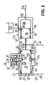
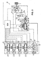
- ein Schaltbild einer hydraulischen Betätigungsvorrichtung für die Betätigung einer Reibkupplung mittels eines Kupplungsstellzylinders und von vier Getriebestellgliedern mittels einer entsprechenden Anzahl von Getriebestellzylindern, bei der der Kupplungsstellzylinder mit der Reibkupplung über eine Reihenschaltung eines Kupplungsgeberzylinders und eines Kupplungsnehmerzylinders wirkverbunden ist, als ein erstes erfindungsgemäßes Ausführungsbeispiel;
- Fig. 2
- eine vergrößerte Darstellung des Details II in
Fig. 1 , der insbesondere weitere Einzelheiten zum Kupplungsstellzylinder zu entnehmen sind; - Fig. 3
- ein Schaltbild einer hydraulischen Betätigungsvorrichtung für die Betätigung einer Reibkupplung und von vier Getriebestellgliedern nach einem zweiten erfindungsgemäßen Ausführungsbeispiel, bei dem im Vergleich zum ersten Ausführungsbeispiel die hydraulische Verbindung zwischen Kupplungsgeberzylinder und Kupplungsnehmerzylinder mit einer Ventilanordnung zur Druckeinstellung versehen ist;
- Fig. 4
- ein Schaltbild einer hydraulischen Betätigungsvorrichtung für die Betätigung einer Reibkupplung und von vier Getriebestellgliedern nach einem dritten erfindungsgemäßen Ausführungsbeispiel, bei dem im Vergleich zum zweiten Ausführungsbeispiel die hydraulische Verbindung zwischen Kupplungsgeberzylinder und Kupplungsnehmerzylinder mit einer anderen Ventilanordnung zur Druckeinstellung und einem Druckspeicher versehen ist; und
- Fig. 5
- ein Schaltbild einer hydraulischen Betätigungsvorrichtung für die Betätigung von zwei Reibkupplungen und vier Getriebestellgliedern in einem Doppelkupplungsgetriebe, als ein viertes erfindungsgemäßes Ausführungsbeispiel, bei dem jeder Reibkupplung eine Reihenschaltung eines Kupplungsgeberzylinders und eines Kupplungsnehmerzylinders mit Ventilanordnung zur Druckeinstellung analog
Fig. 3 zugeordnet ist, wobei der Kupplungsstellzylinder beide Kupplungsgeberzylinder betätigt.
- Fig. 1
- a diagram of a hydraulic actuator for the actuation of a friction clutch means a Kupplungsstellzylinders and four Getriebestellgliedern means of a corresponding number of Getriebestellzylindern, in which the clutch actuating cylinder with the friction clutch via a series circuit of a clutch master cylinder and a clutch slave cylinder is operatively connected, as a first inventive embodiment;
- Fig. 2
- an enlarged view of the detail II in
Fig. 1 , which can be found in particular more details to the clutch actuator cylinder; - Fig. 3
- a circuit diagram of a hydraulic actuator for the operation of a friction clutch and four Getriebestellgliedern according to a second embodiment of the invention, in which compared to the first embodiment, the hydraulic connection between the clutch master cylinder and clutch slave cylinder is provided with a valve arrangement for pressure adjustment;
- Fig. 4
- a circuit diagram of a hydraulic actuator for the operation of a friction clutch and four Getriebestellgliedern according to a third embodiment of the invention, in which compared to the second embodiment, the hydraulic connection between clutch master cylinder and clutch slave cylinder is provided with a different valve arrangement for pressure adjustment and a pressure accumulator; and
- Fig. 5
- 1 is a circuit diagram of a hydraulic actuating device for the actuation of two friction clutches and four gear operating members in a dual-clutch transmission, as a fourth embodiment according to the invention, in which each friction clutch a series connection of a clutch master cylinder and a clutch slave cylinder with valve arrangement for pressure adjustment analog
Fig. 3 is assigned, wherein the clutch actuating cylinder actuates both clutch master cylinder.
In den Zeichnungen - und in der folgenden Beschreibung - wurde auf eine nähere Darstellung bzw. Erläuterung der zu betätigenden Getriebestellglieder (z.B. Schaltmuffen oder Schaltstangen mit Schaltgabeln) und (Trocken- oder Nass-)Reibkupplungen verzichtet, weil diese Elemente und deren Funktion dem Fachmann hinreichend bekannt sind und diesbezügliche Ausführungen für das Verständnis der vorliegenden Erfindung nicht erforderlich erscheinen.In the drawings - and in the following description - has been dispensed with a closer representation or explanation of the actuatable gear actuators (eg shift sleeves or shift rails with shift forks) and (dry or wet) friction clutches, because these elements and their function sufficient to those skilled are known and relevant embodiments for the understanding of the present invention do not appear necessary.
In
Wesentlich ist, dass - wie nachfolgend anhand der
Die Pumpe P der Leistungseinheit 12 weist zwei Hydraulikanschlüsse 34, 36 auf, von denen je nach der gewählten bzw. von dem Steuergerät ECU vorgegebenen Pumprichtung R der eine Anschluss den Pumpeneingang (Sauganschluss), über den das Hydraulikfluid an- bzw. nachgesaugt wird, und der andere Anschluss den Pumpenausgang (Druckanschluss) bildet, über den das Hydraulikfluid mit Druck abgegeben wird. Als Pumpentypen in Frage kommen z.B. Zahnradpumpen, Rollenzellenpumpen, Flügelzellenpumpen und Radial- oder Axial-Kolbenpumpen. Für die vorliegende Anwendung ist es grundsätzlich ausreichend, wenn die Pumpe P als Konstantpumpe ausgeführt ist, die für eine vorbestimmte Drehzahl des Pumpenantriebs M einen konstanten Volumenstrom liefert. Ggf. kann der Pumpenantrieb M in der Drehzahl steuerbar sein, um beispielsweise auf die Stellgeschwindigkeit des Kupplungsstellzylinders CC Einfluss nehmen zu können. Die Bestromung bzw. Ansteuerung des Pumpenantriebs M erfolgt über das in
Jeder Hydraulikanschluss 34, 36 der Pumpe P ist mit dem Vorratsbehälter 14 über eine Ansaugleitung 38, 40 verbunden, in die ein in Richtung des Vorratsbehälters 14 sperrendes Rückschlagventil 42, 44 geschaltet ist. Die Rückschlagventile 42, 44 können in ihre in Richtung des Vorratsbehälters 14 sperrende Stellung vorgespannt sein; dies ist in den Figuren jedoch nicht gezeigt. Darüber hinaus ist an jeden Hydraulikanschluss 34, 36 eine sich verzweigende Druckleitung 46, 48 angeschlossen, die für eine hydraulische Verbindung der Leistungseinheit 12 zum Kupplungsstellzylinder CC und zu den Getriebestellzylindern GC1 bis GC4 sorgt, welche sämtlich bezüglich der Pumpe P parallel geschaltet sind. Insoweit ist für den Fachmann ersichtlich, dass, wenn die Pumpe P z.B. mit einer Pumprichtung R im Uhrzeigersinn in
Im Kupplungsbetätigungsabschnitt 18 führen die Druckleitungen 46, 48 gemäß
In einem drucklosen Bereich des Zylinderraums 56 in axialer Richtung gesehen zwischen den Dichtelementen 62, 64 sind am Kolben 20 mehrere, hier zwei Sperrabschnitte ausgebildet, mit denen das Sperrelement 28 der im dargestellten Ausführungsbeispiel am Kupplungsstellzylinder CC, genauer dessen Zylindergehäuse 54 angebrachten Rastiereinrichtung 26 zusammenwirkt, um den Kolben 20 in einer Ruhestellung (wie gezeigt) oder einer Betätigungsstellung zu halten oder aus der jeweiligen Stellung freizugeben, wie nachfolgend noch näher beschrieben werden wird. Bei den kolbenseitigen Sperrabschnitten handelt es sich im dargestellten Ausführungsbeispiel um axial voneinander beabstandete Aussparungen 66, 68, die am Umfang des Kolbens 20 ausgebildet sind.In an unpressurized region of the
Die Rastiereinrichtung 26 weist ein Gehäuse 70 auf, welches im dargestellten Ausführungsbeispiel auf geeignete Weise am Außenumfang des Zylindergehäuses 54 des Kupplungsstellzylinders CC befestigt ist. In dem Gehäuse 70 ist eine Magnetspule 72 des Aktuators 32 aufgenommen, die das hier als Anker eines Magnetantriebs fungierende, ferromagnetische Sperrelement 28 zumindest teilweise konzentrisch umgibt. Das in der Magnetspule 72 kolbenartig verschiebbare Sperrelement 28 durchgreift eine Öffnung 74 im Gehäuse 70, so dass ein am in
Insoweit ist ersichtlich, dass die Feder 30 bestrebt ist, das Sperrelement 28 aus dem Gehäuse 70 der Rastiereinrichtung 26 herauszudrücken, so dass im unbestromten Zustand der Magnetspule 72 der Rastiervorsprung 76 aufgrund der Kraft der Feder 30 mit einer der Aussparungen 66, 68 am Kolben 20 in Eingriff gehalten wird. Durch den somit bewirkten Formschluss wird der Kolben 20 selbst bei Druckbeaufschlagung einer der Druckräume 58, 60 daran gehindert, sich im Kupplungsstellzylinder CC zu verschieben. Wird die Magnetspule 72 hingegen bestromt, so zieht die resultierende Magnetkraft das Sperrelement 28 entgegen der Kraft der Feder 30 in das Gehäuse 70 in einer Richtung zurück, die im Wesentlichen senkrecht zur Verschieberichtung des Kolbens 20 verläuft, wobei der Rastiervorsprung 76 von der jeweiligen Aussparung 66 bzw. 68 freikommt. Der Kolben 20 kann nun durch Druckbeaufschlagung des entsprechenden Druckraums 58 oder 60 in
Die jeweilige Stellung der Rastiereinrichtung 26 (offen bzw. rastiert), d.h. des Sperrelements 28 bezüglich des Gehäuses 70 der Rastiereinrichtung 26 kann vermittels des Steuergeräts ECU indirekt über die Induktivität des Aktuators 32 ermittelt werden, die sich bei einer Bewegung des Sperrelements 28 relativ zum Gehäuse 70 nach Maßgabe des aktuellen Luftspalts, also des lichten Abstands zwischen dem Sperrelement 28 und dem Bodenbereich 78 des Gehäuses 70 im Bereich der Feder 30 ändert.The respective position of the latching device 26 (open or latched), i. of the locking element 28 with respect to the housing 70 of the latching
Auf der in
Der in an sich bekannter Weise ausgebildete Kupplungsgeberzylinder CM besitzt ein Zylindergehäuse 86, in dem der Geberkolben 84 längsverschieblich aufgenommen ist und einen Druckraum 88 begrenzt. Der Geberkolben 84 ist am Außenumfang mit einem Primärdichtelement 90 und einem Sekundärdichtelement 92 versehen, die gegenüber einer Innenumfangsfläche des Zylindergehäuses 86 dynamisch abdichten und zwischen sich einen Nachlaufbereich 94 begrenzen. In der in
Wie ferner der
Es ist ersichtlich, dass bei einer Betätigung des Kupplungsgeberzylinders CM Hydraulikfluid durch den Geberkolben 84 aus dem Druckraum 88 hinaus geschoben und aufgrund der hydraulischen Verbindung über die Druckleitung 104 in entsprechendem Maße in den Druckraum 110 des Kupplungsnehmerzylinders CS hineingeschoben wird, wo es im Ergebnis zu einer Verschiebung des Nehmerkolbens 108 und damit über die mechanische Verbindung 112 zu einer Ausrückbewegung an der Reibkupplung C kommt. Zurückkommend auf
Wie in der
Was schließlich den Getriebestellabschnitt 16 mit seinen vier doppeltwirkenden Getriebestellzylindern GC1 bis GC4 angeht, die in bezüglich der Pumpe P hydraulischer Parallelschaltung an die Druckleitungen 46, 48 angeschlossen sind, soll hier festgehalten werden, dass die einzelnen Getriebestellzylinder GC1 bis GC4 - wie die schematische Darstellung in
Mit der vorbeschriebenen hydraulischen Betätigungsvorrichtung 10 ist z.B. folgender Betrieb möglich, wobei das Steuergerät ECU den elektrischen Pumpenantrieb M und die elektromagnetischen Aktuatoren 32 der Rastiereinrichtungen 26 an den Stellzylindern CC, GC1 bis GC4 - ggf. unter Berücksichtigung sensierter Kolbenpositionen - geeignet ansteuert und koordiniert.With the above-described
Soll der Kolben 20 des Kupplungsstellzylinders CC für eine Betätigungsbewegung am Kupplungsgeberzylinder CM aus einer vorbestimmten Stellung, die bei diesem Ausführungsbeispiel durch die Sensoreinrichtung 114 bekannt ist, beispielsweise der Ruhestellung gemäß den
Es ist ersichtlich, dass im Gesamtsystem eine Betätigungsbewegung an der Reibkupplung C erzeugt bzw. ein bestimmtes der Getriebestellglieder F1 bis F4 verfahren werden kann, indem das Steuergerät ECU durch Bestromung der Rastiereinrichtung 26 an dem der Reibkupplung C bzw. dem jeweiligen Getriebestellglied F1 bis F4 zugeordneten Stellzylinder CC bzw. GC1 bis GC4 die Kolbenrastierung aufhebt und die Pumpe P nach Maßgabe der gewünschten Stellrichtung mit bestimmter Pumprichtung R anschaltet, während die Kolben der weiteren Stellzylinder über die diesen funktional zugeordneten Rastiereinrichtungen stromlos gehalten werden. Mit dieser Schaltung ist es grundsätzlich auch möglich, mehrere Stellbewegungen in derselben Stellrichtung zugleich auszuführen, indem die entsprechenden Rastiereinrichtungen und der Pumpenantrieb M zur selben Zeit bestromt werden, worauf sich die druckbeaufschlagten freigegebenen Kolben in derselben Stellrichtung bewegen.It can be seen that in the overall system an actuating movement is generated at the friction clutch C or a specific one of the transmission actuator members F1 to F4 can be moved by the ECU ECU by energizing the
Kupplungs- und Schaltvorgänge können demgemäß stichwortartig beschrieben wie folgt ausgeführt werden:
- A. Anfahren: Das Steuergerät ECU erhält von der übergeordneten Getriebesteuerung das Signal zum Anfahren sowie Informationen über die geforderte Dynamik. Alle elektrischen Bauteile außer den Wegsensoren sind stromlos, wenn nicht anders angegeben; anfangs sind alle Stellzylinder CC, GC1 bis GC4 in Ruhestellung rastiert (Eingriff in
Aussparungen 66 bzw. b1 bis b4).- A.1 Zum Öffnen der Reibkupplung C wird die
Rastiereinrichtung 26 am Kupplungsstellzylinder CC bestromt, die Pumpe P wird rechtsdrehend eingeschaltet, worauf derKolben 20 im Kupplungsstellzylinder CC nach rechts verfährt und den Kupplungsgeberzylinder CM betätigt. Die Position des Kolbens 20 wird hierbei über dieintegrierte Sensoreinrichtung 114 erfasst. Somit wird der Kupplungsnehmerzylinder CS hydraulisch angesteuert und öffnet die Reibkupplung C. In Endstellung des Kolbens 20 wird die Rastiereinrichtung 26 entstromt und hältdamit den Kolben 20 in Position (Rastiervorsprung 76 stehtmit Aussparung 68 in Eingriff); die Pumpe P wird abgeschaltet. - A.2 Zum Einlegen des geforderten Gangs - sofern der 1. Vorwärtsgang G1 oder der Rückwärtsgang GR nicht bereits eingelegt ist - wird wie folgt vorgegangen. Ist der 1. Vorwärtsgang G1 einzulegen, wird die Rastiereinrichtung am Getriebestellzylinder GC1 bestromt; die Pumpe P wird wiederum rechtsdrehend eingeschaltet. Demgemäß verfährt der Kolben im Getriebestellzylinder GC1 nach links, so dass über das Getriebestellglied F1 der 1. Vorwärtsgang G1 eingelegt wird. Der Kolben des Getriebestellzylinders GC1 wird sodann in dieser Position durch Entstromen der zugeordneten Rastiereinrichtung festgehalten (Eingriff in Aussparung c1).
- A.3 Für den eigentlichen Anfahrvorgang wird die Pumpe P zunächst rechtsdrehend betrieben, um die Rastierung am Kupplungsstellzylinder CC zu entlasten. Sodann wird die
Rastiereinrichtung 26 am Kupplungsstellzylinder CC bestromt, die Pumpe P auf linksdrehend umgeschaltet und derKolben 20 im Kupplungsstellzylinder CC weggeregelt verfahren, um die Reibkupplung C in definierter Weise einzurücken und somit mit dem Kraftfahrzeug entsprechend der geforderten Dynamik anzufahren. Ist die Ruhestellung erreicht, verrastet die entstromte Rastiereinrichtung 26 den Kolben 20 (Rastiervorsprung 76 stehtmit Aussparung 66 in Eingriff); die Pumpe P wird abgeschaltet.
- A.1 Zum Öffnen der Reibkupplung C wird die
- B. Gangwechsel: Das Steuergerät ECU erhält von der übergeordneten Getriebesteuerung das Signal für einen Gangwechsel. Alle elektrischen Bauteile außer den Wegsensoren sind stromlos, wenn nicht anders angegeben; der Kupplungsstellzylinder CC ist in Ruhestellung rastiert, die Getriebestellzylinder GC1 bis GC4 in ihrer jeweiligen Stellung.
- B.1 Für einen Gangwechsel wird zunächst die Reibkupplung C wie oben unter A.1 beschrieben geöffnet.
- B.2 Um den 1. Vorwärtsgang G1 herauszunehmen, wird die Rastiereinrichtung am Getriebestellzylinder GC1 bestromt. Die Pumpe P wird linksdrehend betrieben, so dass das Getriebestellglied F1 nach rechts gezogen wird. Hat der Kolben des Getriebestellzylinders GC1 die Mittelstellung erreicht, wird er durch Entstromen der zugeordneten Rastiereinrichtung festgehalten (Eingriff in Aussparung b1).
- B.3 Um den 2. Vorwärtsgang G2 einzulegen, wird die Rastiereinrichtung am Getriebestellzylinder GC2 bestromt. Die Pumpe P wird rechtsdrehend betrieben, so dass das Getriebestellglied F2 nach links geschoben wird. Hat der Kolben des Getriebestellzylinders GC2 seine linke Stellung erreicht, wird er durch Entstromen der zugeordneten Rastiereinrichtung festgehalten (Eingriff in Aussparung c2).
- B.4 Um die Reibkupplung C zu schließen, wird die Pumpe P zunächst rechtsdrehend betrieben, so dass die Rastierung am Kupplungsstellzylinder CC entlastet ist. Sodann wird die
Rastiereinrichtung 26 am Kupplungsstellzylinder CC bestromt, die Pumpe P auf linksdrehend umgeschaltet und derKolben 20 im Kupplungsstellzylinder CC weggeregelt verfahren, so dass die Reibkupplung C mit der geforderten Dynamik geschlossen wird. Ist die Ruhestellung erreicht, verrastet die entstromte Rastiereinrichtung 26 den Kolben 20 (Rastiervorsprung 76 stehtmit Aussparung 66 in Eingriff); die Pumpe P wird abgeschaltet.
- A. Starting: The control unit ECU receives from the higher-level transmission control the signal for starting and information about the required dynamics. All electrical components except the displacement sensors are de-energized, unless stated otherwise; Initially, all adjusting cylinders CC, GC1 to GC4 are rested in rest position (engagement in
recesses 66 or b1 to b4).- A.1 To open the friction clutch C, the locking
device 26 is energized on the clutch actuator CC, the pump P is turned clockwise, whereupon thepiston 20 moves in the clutch actuator CC to the right and the clutch master cylinder CM is actuated. The position of thepiston 20 is detected by theintegrated sensor device 114. Thus, the clutch slave cylinder CS is hydraulically actuated and opens the friction clutch C. In the end position of thepiston 20 is theRastiereinrichtung 26 de-energized and thus holds thepiston 20 in position (Rastiervorsprung 76 is withrecess 68 into engagement); the pump P is switched off. - A.2 The following procedure is used to engage the required gear - provided that the first forward gear G1 or the reverse gear GR has not already been engaged. If the 1st forward gear G1 is to be engaged, the locking device is energized on the gearbox cylinder GC1; the pump P is again turned clockwise. Accordingly, the piston moves in the gearbox cylinder GC1 to the left, so that via the transmission actuator F1 of the first forward gear G1 is inserted. The piston of the Getriebestellzylinders GC1 is then held in this position by Entstromen the associated locking device (engagement in recess c1).
- A.3 For the actual starting process, the pump P is initially operated in a clockwise direction to relieve the detent on the clutch actuator cylinder CC. Then, the locking
device 26 is energized on the clutch actuator CC, the pump P is switched to left-handed and thepiston 20 in the clutch actuator CC weggeregelt procedure to engage the friction clutch C in a defined manner and thus approach the motor vehicle according to the required dynamics. When the rest position is reached, thede-energized latching device 26 locks the piston 20 (latchingprojection 76 is in engagement with recess 66); the pump P is switched off.
- A.1 To open the friction clutch C, the locking
- B. Gear change: The ECU receives from the higher transmission control the signal for a gear change. All electrical components except the displacement sensors are de-energized, unless stated otherwise; the clutch actuator cylinder CC is locked in the rest position, the gear actuator cylinders GC1 to GC4 in their respective position.
- B.1 For a gear change, the friction clutch C is first opened as described above under A.1.
- B.2 In order to remove the 1st forward gear G1, the locking device is energized on the gear actuator cylinder GC1. The pump P is operated counterclockwise, so that the transmission actuator F1 is pulled to the right. If the piston of the Getriebestellzylinders GC1 has reached the middle position, it is held by Entstromen the associated locking device (engaging in recess b1).
- B.3 In order to engage the 2nd forward gear G2, the locking device is energized on the gear actuator cylinder GC2. The pump P is operated clockwise, so that the transmission actuator F2 is pushed to the left. If the piston of the Getriebestellzylinders GC2 has reached its left position, it is held by Entstromen the associated locking device (engagement in recess c2).
- B.4 To close the friction clutch C, the pump P is initially operated clockwise, so that the detent is relieved at the clutch actuator CC. Then, the locking
device 26 is energized on the clutch actuator CC, the pump P is switched to left-handed and thepiston 20 moved away in the clutch actuator CC, so that the friction clutch C is closed with the required dynamics. When the rest position is reached, thede-energized latching device 26 locks the piston 20 (latchingprojection 76 is in engagement with recess 66); the pump P is switched off.
Bei den anderen Gängen wird in analoger Weise verfahren, so dass diesbezügliche Erläuterungen an dieser Stelle entbehrlich sind.The other courses are handled in an analogous manner, so that explanations in this regard are unnecessary.
Die weiteren Ausführungsbeispiele gemäß den
Bei dem zweiten Ausführungsbeispiel sind gemäß
Das Proportional-Drosselventil 124 ist im dargestellten Ausführungsbeispiel als elektromagnetisch betätigbares, im nicht angesteuerten Zustand in Durchgangs-Null-Stellung geschaltetes 2/2 Kugelsitzventil ausgeführt, wie es prinzipiell aus der
Demgemäß muss zum Öffnen bzw. Ausrücken der Reibkupplung C das Proportional-Drosselventil 124 bestromt werden, um Letzteres zu schließen, so dass sich im Kupplungsnehmerzylinder CS überhaupt ein Druck aufbauen kann, wenn der Kupplungsgeberzylinder CM wie oben beschrieben vom Kupplungsstellzylinder CC betätigt wird. Zum Schließen bzw. Einrücken der Reibkupplung C ist es dann nicht erforderlich, die Pumpe P zu betreiben, anders als beim ersten Ausführungsbeispiel; dies kann vielmehr feinfühlig unter geeigneter elektrischer Ansteuerung des Proportional-Drosselventils 124 zur variablen Einstellung des Drosselspalts erfolgen. Allerdings muss der Kupplungsstellzylinder CC zugleich oder danach wieder in seinen Ausgangs- oder Ruhezustand gebracht werden, und zwar durch Aufheben der Verrastung des Kolbens 20 in der Betätigungsstellung durch Bestromen der Rastiereinrichtung 26, Verschieben des Kolbens 20 durch linksdrehendes Betreiben der Pumpe P und schließlich Verrastung des Kolbens 20 in der Ruhestellung durch Entstromen der Rastiereinrichtung 26.Accordingly, in order to open or disengage the friction clutch C, the
Auch bei dem in
In
Zum Betrieb der Betätigungsvorrichtung 10 gemäß dem dritten Ausführungsbeispiel ist zunächst anzumerken, dass das Schaltventil 130 - wenn die Reibkupplung C nicht gerade geöffnet werden soll - periodisch, d.h. in regelmäßigen Abständen bestromt wird, um einen Volumensausgleich zu gewährleisten, der infolge von Wärmedehnungen etc. erforderlich sein kann.For operation of the
Das Aus- und Einrücken der Reibkupplung C erfolgt dann wie folgt: Zunächst wird zum Füllen des (Feder)Druckspeichers 128 die Rastiereinrichtung 26 bestromt und die Pumpe P rechtsdrehend eingeschaltet, so dass der Kupplungsstellzylinder CC den Kupplungsgeberzylinder CM betätigt. Die Federvorspannung am Proportional-Drosselventil 124 ist hierbei so hoch, dass das infolge der Betätigung des Kupplungsgeberzylinders CM verdrängte Volumen an Hydraulikfluid in den Druckspeicher 128 gedrückt wird; das Rückschlagventil 122 und das sperrende Schaltventil 130 halten den Druck. Dann wird die Pumpe P linksdrehend betrieben, bis der Kolben 20 seine Ruhestellung erreicht. Dabei saugt der Kupplungsgeberzylinder CM über den Nachlaufanschluss 98 Hydraulikfluid aus dem Ausgleichsbehälter 100 nach, so dass er für die nächste Betätigung bereit ist. Ggf. können mehrere solcher Betätigungen des Kupplungsgeberzylinders CM über den Kupplungsstellzylinder CC erfolgen, bis der Druckspeicher 128 hinreichend gefüllt ist. Anschließend wird die Rastiereinrichtung 26 entstromt und verriegelt den Kolben 20 des Kupplungsstellzylinders CC; die Pumpe P wird abgeschaltet.The disengagement and engagement of the friction clutch C then takes place as follows: First, the latching
Das Öffnen bzw. Ausrücken der Reibkupplung C erfolgt danach alleine durch geeignetes Bestromen des Proportional-Drosselventils 124, wobei der Druckspeicher 128 den für die Betätigung des Kupplungsnehmerzylinders CS erforderlichen Druck liefert.The opening or disengaging the friction clutch C is then carried out solely by suitable energizing the
Zum Schließen bzw. Einrücken der Reibkupplung C wird zunächst das Schaltventil 130 bestromt, um die Druckleitung 104 mit der Ablaufleitung 126 zu verbinden. Schließlich wird das Proportional-Drosselventil 124 geeignet angesteuert, um den Kupplungsnehmerzylinder CS definiert hydraulisch zu entlasten und dabei eine weggeregelte Einrückbewegung zu bewirken.To close or engage the friction clutch C, the switching
Das in
Anders als bei den vorhergehenden Ausführungsbeispielen ist am Kolben 20 ferner eine weitere Aussparung 67 vorgesehen, so dass dieser insgesamt drei Aussparungen 66, 67, 68 besitzt. Die mittlere Aussparung 67 definiert hierbei die Grund- oder Ruhestellung des Kolbens 20 im Kupplungsstellzylinder CC, die in
Für den Fachmann ist ersichtlich, dass somit ein überschneidender Betrieb der Reibkupplungen C, C' möglich ist. Soll z.B. der Gang vom ersten Vorwärtsgang G1 in den zweiten Vorwärtsgang G2 gewechselt werden, kann - ausgehend von einem Zustand, bei dem die dem ersten Vorwärtsgang G1 zugeordnete Reibkupplung C' geschlossen ist, während die dem zweiten Vorwärtsgang G2 zugeordnete Reibkupplung C mit bestromten Proportional-Drosselventil 124 geöffnet gehalten wird - stichwortartig beschrieben wie folgt vorgegangen werden.
- C.1 Einlegen des zweiten Gangs im "losen" Teilgetriebe: Rastiereinrichtung am Getriebestellzylinder GC2 bestromen; Pumpe P rechtsdrehend betreiben und damit den zweiten Vorwärtsgang G2 einlegen; Rastiereinrichtung am Getriebestellzylinder GC2 entstromen und somit den entsprechenden Stellzylinderkolben fixieren (Eingriff in Aussparung c2; vgl.
Fig. 1 ). - C.2 "Überschneiden" der Kupplungen:
Rastiereinrichtung 26 am Kupplungsstellzylinder CC und Proportional-Drosselventil 124' bestromen; Pumpe P linksdrehend betreiben und damit den Kupplungsgeberzylinder CM' betätigen; Letzter steuert den Kupplungsnehmerzylinder CS' hydraulisch an, der die Reibkupplung C' öffnet. Parallel dazu: geregeltes Entstromen des Proportional-Drosselventils 124, so dass der Kupplungsnehmerzylinder CS hydraulisch entlastet und die Reibkupplung C geschlossen wird. In (linker) Endstellung des Kolbens 20 im Kupplungsstellzylinder CC wird dieRastiereinrichtung 26 entstromt, so dass derKolben 20 in Position gehalten wird (Eingriff in Aussparung 66). - C.3 Herausnehmen des 1. Gangs im jetzt "losen" Teilgetriebe: Rastiereinrichtung am Getriebestellzylinder GC1 bestromen; Pumpe P linksdrehend betreiben, wodurch der erste Vorwärtsgang G1 herausgezogen wird; Rastiereinrichtung am Getriebestellzylinder GC1 entstromen, sobald der entsprechende Stellzylinderkolben seine Mittelstellung erreicht hat, in der er somit verrastet wird (Eingriff in Aussparung b1; vgl.
Fig. 1 ). - C.4 Ausgangsstellung des Kupplungsstellzylinders CC wieder herstellen: Parallel zu oder nach dem Herausnehmen des ersten Vorwärtsgangs G1 wird die
Rastiereinrichtung 26 bestromt und die Pumpe P linksdrehend betrieben,bis der Kolben 20 seine Ruhestellung erreicht hat, in der dieRastiereinrichtung 26 entstromt wird und somitden Kolben 20 verrastet (Eingriff in Aussparung 67).
- C.1 Inserting the second gear in the "loose" partial gearbox: energize the locking device on the gearbox cylinder GC2; Operate pump P clockwise and thus insert the second forward gear G2; Triggering device on the gear actuator cylinder GC2 and thus fix the corresponding adjusting cylinder piston (engagement in recess c2;
Fig. 1 ). - C.2 "overlapping" of the clutches: energize the
locking device 26 on the clutch control cylinder CC and the proportional throttle valve 124 '; Operate pump P anti-clockwise and thus actuate clutch master cylinder CM '; The latter controls the clutch slave cylinder CS 'hydraulically, which opens the friction clutch C'. Parallel to this: controlled flow of theproportional throttle valve 124, so that the clutch slave cylinder CS relieved hydraulically and the friction clutch C is closed. In (left) end position of thepiston 20 in the clutch actuator CC, the lockingdevice 26 is de-energized, so that thepiston 20 is held in position (engagement in recess 66). - C.3 Removal of 1st gear in the now "loose" partial gearbox: Energize locking device on gearbox cylinder GC1; Operate pump P counterclockwise, whereby the first forward gear G1 is pulled out; Disengaged on the gear actuator cylinder GC1 as soon as the corresponding actuating cylinder piston has reached its middle position, in which it is thus locked (engagement in recess b1;
Fig. 1 ). - C.4 restore starting position of the clutch actuator CC: Parallel to or after removing the first forward gear G1 the latching
device 26 is energized and the pump P operated counterclockwise until thepiston 20 has reached its rest position in which thelatching device 26 is de-energized and thus thepiston 20 is locked (engagement in recess 67).
Ein Wechsel zwischen den anderen Gängen kann in analoger Weise erfolgen, diesbezügliche Ausführungen sind insofern entbehrlich.A change between the other courses can be done in an analogous manner, this statement is unnecessary.
Eine hydraulische Betätigungsvorrichtung für wenigstens eine Reibkupplung und mindestens ein Getriebestellglied umfasst eine Leistungseinheit zur Druckerzeugung mittels einer elektroangetriebenen Pumpe, daran hydraulisch angeschlossene Getriebestell- und Kupplungsbetätigungsabschnitte mit Getriebestell- und Kupplungsstellzylindern sowie ein elektrisches Steuergerät zur Steuerung dieser Baugruppen. Einem Kolben des Kupplungsstellzylinders, der mit der Reibkupplung wirkverbunden und auf gegenüberliegenden Seiten hydraulisch beaufschlagbar ist, ist eine Rastiereinrichtung mit einem Sperrelement zugeordnet, das in eine eine Kolbenbewegung verhindernde Sperrstellung federvorgespannt ist und welches mittels eines über das Steuergerät ansteuerbaren Aktuators von der Sperrstellung in eine eine Kolbenbewegung zulassende Lösestellung bewegbar ist. Dabei ist eine Pumprichtung der Pumpe umkehrbar, um den Kolben für eine Betätigungsbewegung je nach Pumprichtung auf der einen oder anderen Seite zu beaufschlagen. Das Steuergerät koordiniert die Ansteuerung von Pumpenantrieb und Aktuator, um die Reibkupplung aus- bzw. einzurücken.A hydraulic actuator for at least one friction clutch and at least one transmission actuator comprises a power unit for generating pressure by means of an electrically driven Pump, hydraulically connected Getriebestell- and Kupplungsbetätigungsabschnitte with Getriebestell- and Kupplungsstellzylindern and an electrical control unit for controlling these modules. A piston of the clutch actuating cylinder, which is operatively connected to the friction clutch and hydraulically acted upon on opposite sides, a locking device is associated with a locking element which is spring-biased in a piston movement preventing blocking position and which by means of an activatable via the control unit actuator from the blocking position into a Piston movement permitting release position is movable. In this case, a pumping direction of the pump is reversible, to act on the piston for an actuating movement depending on the pumping direction on one side or the other. The control unit coordinates the activation of the pump drive and actuator in order to disengage or engage the friction clutch.
- 1010
- hydraulische Betätigungsvorrichtunghydraulic actuator
- 1212
- Leistungseinheitpower unit
- 1414
- Vorratsbehälterreservoir
- 1616
- GetriebestellabschnittTransmission actuator section
- 1818
- KupplungsbetätigungsabschnittClutch Control Section
- 2020
- Kolbenpiston
- 2222
- Seitepage
- 2424
- Seitepage
- 2626
- Rastiereinrichtunglocking device
- 2828
- Sperrelementblocking element
- 3030
- Federfeather
- 3232
- Aktuatoractuator
- 3434
- Hydraulikanschlusshydraulic connection
- 3636
- Hydraulikanschlusshydraulic connection
- 3838
- Ansaugleitungsuction
- 4040
- Ansaugleitungsuction
- 4242
- Rückschlagventilcheck valve
- 4444
- Rückschlagventilcheck valve
- 4646
- Druckleitungpressure line
- 4848
- Druckleitungpressure line
- 5050
- Druckanschlusspressure connection
- 5252
- Druckanschlusspressure connection
- 5454
- Zylindergehäusecylinder housing
- 5656
- Zylinderraumcylinder space
- 5858
- Druckraumpressure chamber
- 6060
- Druckraumpressure chamber
- 6262
- Dichtelementsealing element
- 6464
- Dichtelementsealing element
- 6666
- Aussparungrecess
- 6767
- Aussparungrecess
- 6868
- Aussparungrecess
- 7070
- Gehäusecasing
- 7272
- Magnetspulesolenoid
- 7474
- Öffnungopening
- 7676
- RastiervorsprungRastiervorsprung
- 7878
- Bodenbereichfloor area
- 80, 80'80, 80 '
- Kolbenstangepiston rod
- 8282
- Wandungwall
- 84, 84'84, 84 '
- Geberkolbenmaster piston
- 86, 86'86, 86 '
- Zylindergehäusecylinder housing
- 88, 88'88, 88 '
- Druckraumpressure chamber
- 9090
- PrimärdichtelementPrimary sealing element
- 9292
- SekundärdichtelementSecondary sealing element
- 9494
- Nachlaufbereichrunning area
- 9696
- Nachlaufverbindungfollow-up connection
- 9898
- Nachlaufanschlusstrailing connection
- 100, 100'100, 100 '
- Ausgleichsbehältersurge tank
- 102, 102'102, 102 '
- Druckanschlusspressure connection
- 104, 104'104, 104 '
- Druckleitungpressure line
- 106, 106'106, 106 '
- Zylindergehäusecylinder housing
- 108, 108'108, 108 '
- Nehmerkolbenslave piston
- 110, 110'110, 110 '
- Druckraumpressure chamber
- 112, 112'112, 112 '
- mechanische Verbindungmechanical connection
- 114, 114'114, 114 '
- Sensoreinrichtungsensor device
- 116116
- Sensorsensor
- 118118
- Signalelementsignal element
- 120, 120'120, 120 '
- HubsensorikHubsensorik
- 122, 122'122, 122 '
- Rückschlagventilcheck valve
- 124, 124'124, 124 '
- Proportional-DrosselventilProportional throttle valve
- 126, 126'126, 126 '
- Ablaufleitungdrain line
- 128128
- Druckspeicheraccumulator
- 130130
- Schaltventilswitching valve
- 132132
- Drucksensorpressure sensor
- a1 - a4a1 - a4
- Sperraussparungenlocking recesses
- b1 - b4b1 - b4
- Sperraussparungenlocking recesses
- c1 - c4c1 - c4
- Sperraussparungenlocking recesses
- C, C'C, C '
- Reibkupplungfriction clutch
- CCCC
- KupplungsstellzylinderClutch actuator cylinder
- CM, CM'CM, CM '
- KupplungsgeberzylinderClutch Master Cylinder
- CS, CS'CS, CS '
- KupplungsnehmerzylinderClutch slave cylinder
- ECUECU
- Steuergerätcontrol unit
- F1 - F4F1 - F4
- GetriebestellgliederGear actuators
- G1 - G7G1 - G7
- Vorwärtsgängeforward gears
- GC1 - GC4GC1 - GC4
- GetriebestellzylinderGear actuator cylinder
- GRGR
- Rückwärtsgangreverse gear
- PP
- Pumpepump
- MM
- elektrischer Pumpenantriebelectric pump drive
- RR
- Pumprichtungpumping direction
Claims (10)
Applications Claiming Priority (1)
| Application Number | Priority Date | Filing Date | Title |
|---|---|---|---|
| DE102013000157.9A DE102013000157B3 (en) | 2013-01-09 | 2013-01-09 | Hydraulic actuating device for the actuation of at least one friction clutch and at least one transmission actuator in a motor vehicle |
Publications (2)
| Publication Number | Publication Date |
|---|---|
| EP2754911A1 true EP2754911A1 (en) | 2014-07-16 |
| EP2754911B1 EP2754911B1 (en) | 2015-03-18 |
Family
ID=49880091
Family Applications (1)
| Application Number | Title | Priority Date | Filing Date |
|---|---|---|---|
| EP13006057.7A Active EP2754911B1 (en) | 2013-01-09 | 2013-12-28 | Hydraulic actuation device for actuating at least a friction clutch and at least one gear actuator in a motor vehicle |
Country Status (4)
| Country | Link |
|---|---|
| EP (1) | EP2754911B1 (en) |
| JP (1) | JP5951653B2 (en) |
| CN (1) | CN103912678B (en) |
| DE (1) | DE102013000157B3 (en) |
Cited By (3)
| Publication number | Priority date | Publication date | Assignee | Title |
|---|---|---|---|---|
| DE102018008943A1 (en) | 2018-11-14 | 2020-05-14 | Fte Automotive Gmbh | Method for venting a device for the hydraulic actuation of at least one friction clutch and / or at least one transmission actuator |
| EP3670972A1 (en) | 2018-12-19 | 2020-06-24 | FTE automotive GmbH | Hydraulic operating apparatus for the operation of actuating elements in a motor vehicle transmission |
| DE102018009853A1 (en) | 2018-12-19 | 2020-06-25 | Fte Automotive Gmbh | Hydraulic actuating device for actuating actuators in a motor vehicle transmission |
Families Citing this family (16)
| Publication number | Priority date | Publication date | Assignee | Title |
|---|---|---|---|---|
| DE112015001613A5 (en) * | 2014-04-01 | 2016-12-15 | Schaeffler Technologies AG & Co. KG | transmission control |
| DE102014011176A1 (en) * | 2014-07-31 | 2016-02-04 | Fte Automotive Gmbh | Hydraulic actuator for actuating actuators in a motor vehicle transmission |
| DE102014216714A1 (en) | 2014-08-22 | 2016-02-25 | Schaeffler Technologies AG & Co. KG | Apparatus and method for actuating actuators |
| DE102015207930A1 (en) * | 2015-04-29 | 2016-11-03 | Zf Friedrichshafen Ag | Device for actuating a plurality of switching elements of a transmission device |
| DE102015214978A1 (en) | 2015-08-06 | 2017-02-09 | Schaeffler Technologies AG & Co. KG | Apparatus and method for actuating actuators |
| DE102016217381A1 (en) * | 2015-09-29 | 2017-03-30 | Schaeffler Technologies AG & Co. KG | Fluid arrangement for the fluidic actuation of motor vehicle components |
| DE102016000707A1 (en) * | 2016-01-26 | 2017-07-27 | Fte Automotive Gmbh | Device for actuating a clutch |
| DE112017004504B4 (en) | 2016-10-07 | 2022-08-18 | Eaton Intelligent Power Limited | HYDRAULICALLY ACTUATED DIFFERENTIAL |
| DE102018203166A1 (en) * | 2018-03-02 | 2019-09-05 | Zf Friedrichshafen Ag | Parking lock in a transmission of a motor vehicle |
| DE102018106174A1 (en) * | 2018-03-16 | 2019-09-19 | Schaeffler Technologies AG & Co. KG | Method for controlling a clutch actuator |
| DE102018108638B3 (en) * | 2018-04-11 | 2019-05-16 | Hoerbiger Automatisierungstechnik Holding Gmbh | hydraulic system |
| DE102018214435A1 (en) * | 2018-08-27 | 2020-02-27 | Zf Friedrichshafen Ag | Hydraulic system for actuating a plurality of double-acting actuators of a transmission |
| DE102018126552A1 (en) * | 2018-10-24 | 2020-04-30 | Fte Automotive Gmbh | Hydraulic transmission actuator and assembly with such a transmission actuator and a transmission for a drive train of a motor vehicle |
| DE102018126550B4 (en) * | 2018-10-24 | 2024-02-29 | Valeo Powertrain Gmbh | Hydraulic transmission actuator |
| DE102019118124A1 (en) * | 2019-07-04 | 2021-01-07 | Schaeffler Technologies AG & Co. KG | Filter unit for filtering a fluid in a hydraulic line and a coupling system with the filter unit |
| DE102021126828A1 (en) | 2021-10-15 | 2023-04-20 | Schaeffler Technologies AG & Co. KG | Torque transmission device with a locking device that fixes an actuating element |
Citations (5)
| Publication number | Priority date | Publication date | Assignee | Title |
|---|---|---|---|---|
| DE19633420A1 (en) | 1995-09-15 | 1997-03-20 | Ebern Fahrzeugtech Gmbh | Clutch control system particularly for motor vehicle |
| DE10360611A1 (en) | 2003-12-19 | 2005-07-21 | Fte Automotive Gmbh & Co. Kg | Hydraulic function block |
| DE60124444T2 (en) * | 2000-03-24 | 2007-09-20 | Renault S.A.S. | Hydraulic control arrangement for gearshift in an automatic transmission of a vehicle |
| EP2532914A1 (en) * | 2011-06-07 | 2012-12-12 | FTE automotive GmbH | Hydraulic actuation device for actuating clutches, particularly in a multi-clutch transmission system for motor vehicles |
| DE102011107263A1 (en) | 2011-07-06 | 2013-01-10 | Fte Automotive Gmbh | Hydraulic actuating device for the actuation of one or more actuators in particular a motor vehicle transmission |
Family Cites Families (5)
| Publication number | Priority date | Publication date | Assignee | Title |
|---|---|---|---|---|
| US5850898A (en) * | 1995-09-15 | 1998-12-22 | Fahrzeugtechnik Ebern Gmbh | Method and device for the hydraulic actuation of a clutch, especially for automobiles |
| DE102004031021B4 (en) * | 2004-06-26 | 2009-06-10 | Zf Friedrichshafen Ag | Transmission arrangement with a switching element-securing device for securing against insertion of multiple gears of a gearbox or a partial transmission of a gearbox |
| JP2008121796A (en) * | 2006-11-13 | 2008-05-29 | Jtekt Corp | Hydraulic operated clutch device and driving force transmission device using the same as clutch mechanism |
| US7614223B2 (en) * | 2007-03-30 | 2009-11-10 | Clark Equipment Company | Method for operating a multiple speed hydraulic motor |
| GB2475844B (en) * | 2009-12-01 | 2017-01-04 | Gm Global Tech Operations Llc | Oil supply system for an automatic transmission of a vehicle, an automatic transmission and a vehicle comprising the oil supply system |
-
2013
- 2013-01-09 DE DE102013000157.9A patent/DE102013000157B3/en not_active Expired - Fee Related
- 2013-12-25 CN CN201310727031.2A patent/CN103912678B/en active Active
- 2013-12-28 EP EP13006057.7A patent/EP2754911B1/en active Active
-
2014
- 2014-01-09 JP JP2014002369A patent/JP5951653B2/en active Active
Patent Citations (5)
| Publication number | Priority date | Publication date | Assignee | Title |
|---|---|---|---|---|
| DE19633420A1 (en) | 1995-09-15 | 1997-03-20 | Ebern Fahrzeugtech Gmbh | Clutch control system particularly for motor vehicle |
| DE60124444T2 (en) * | 2000-03-24 | 2007-09-20 | Renault S.A.S. | Hydraulic control arrangement for gearshift in an automatic transmission of a vehicle |
| DE10360611A1 (en) | 2003-12-19 | 2005-07-21 | Fte Automotive Gmbh & Co. Kg | Hydraulic function block |
| EP2532914A1 (en) * | 2011-06-07 | 2012-12-12 | FTE automotive GmbH | Hydraulic actuation device for actuating clutches, particularly in a multi-clutch transmission system for motor vehicles |
| DE102011107263A1 (en) | 2011-07-06 | 2013-01-10 | Fte Automotive Gmbh | Hydraulic actuating device for the actuation of one or more actuators in particular a motor vehicle transmission |
Cited By (5)
| Publication number | Priority date | Publication date | Assignee | Title |
|---|---|---|---|---|
| DE102018008943A1 (en) | 2018-11-14 | 2020-05-14 | Fte Automotive Gmbh | Method for venting a device for the hydraulic actuation of at least one friction clutch and / or at least one transmission actuator |
| EP3670972A1 (en) | 2018-12-19 | 2020-06-24 | FTE automotive GmbH | Hydraulic operating apparatus for the operation of actuating elements in a motor vehicle transmission |
| DE102018009853A1 (en) | 2018-12-19 | 2020-06-25 | Fte Automotive Gmbh | Hydraulic actuating device for actuating actuators in a motor vehicle transmission |
| DE102018009852A1 (en) | 2018-12-19 | 2020-06-25 | Fte Automotive Gmbh | Hydraulic actuating device for actuating actuators in a motor vehicle transmission |
| DE102018009853B4 (en) | 2018-12-19 | 2022-12-01 | Fte Automotive Gmbh | Hydraulic actuator for operating actuators in a motor vehicle transmission |
Also Published As
| Publication number | Publication date |
|---|---|
| JP5951653B2 (en) | 2016-07-13 |
| DE102013000157B3 (en) | 2014-01-23 |
| CN103912678B (en) | 2016-11-16 |
| CN103912678A (en) | 2014-07-09 |
| JP2014145480A (en) | 2014-08-14 |
| EP2754911B1 (en) | 2015-03-18 |
Similar Documents
| Publication | Publication Date | Title |
|---|---|---|
| EP2754911B1 (en) | Hydraulic actuation device for actuating at least a friction clutch and at least one gear actuator in a motor vehicle | |
| EP2543891B1 (en) | Combination of a hydraulic actuation device, a controller and one or more positioning members actuated by the hydraulic actuation device for a motor vehicle transmission | |
| EP3084273B1 (en) | Fluid arrangement | |
| EP2382404B1 (en) | Control device for an automatic gear shifting transmission | |
| EP2382402B1 (en) | Hydraulic control for an automatic transmission | |
| EP2532914B1 (en) | Hydraulic actuation device for actuating clutches, particularly in a multi-clutch transmission system for motor vehicles | |
| EP1517059B1 (en) | Double clutch gearing with position holding function | |
| EP2587097B1 (en) | Gear shift assembly for a motor vehicle transmission system | |
| EP2545305B1 (en) | Hydraulic system for actuating an interlocking switching element of a gearing device | |
| EP2382403B1 (en) | Control device for an automatic gear shifting transmission | |
| DE102007044431A1 (en) | Electrohydraulic control device | |
| DE102014018123A1 (en) | Parking lock device | |
| DE102012200202A1 (en) | Hydraulic shift device for an automatic transmission | |
| DE102014105160A1 (en) | Coupling arrangement and method for its operation | |
| DE102016118423A1 (en) | Electro-hydraulic system for the actuation of clutch (s) and gear (s) of manual transmissions | |
| DE102017113790A1 (en) | Electromagnet with selective locking for an electromagnetically actuated valve | |
| DE102015211305B3 (en) | Pressure-dependent insertable parking brake for hydraulic manual transmission | |
| DE102018208755A1 (en) | Pressure control valve | |
| DE102016004366A1 (en) | Pneumatic control device of an automated manual transmission and method for its control | |
| DE102011084587B4 (en) | Device for selecting an operating state of a transmission device | |
| DE2212679B2 (en) | Hydraulic switching device for powershift transmissions with protection against incorrect shifting | |
| WO2003025435A1 (en) | Gear shift actuator | |
| DE102009005752A1 (en) | Control device i.e. hydraulic control device, for dual clutch transmission of motor vehicle, has emergency slide, where pressure of gear actuation system acts as emergency-control pressure at emergency slide | |
| DE102009005754A1 (en) | Hydraulic controller for dual clutch transmission in motor vehicle, has lubricating-cooling system including controllable cooling slider that opens and closes cooling channel, which is arranged parallel to another cooling channel | |
| DE102015225858A1 (en) | Switching valve, in particular for a hydraulic system |
Legal Events
| Date | Code | Title | Description |
|---|---|---|---|
| PUAI | Public reference made under article 153(3) epc to a published international application that has entered the european phase |
Free format text: ORIGINAL CODE: 0009012 |
|
| 17P | Request for examination filed |
Effective date: 20131228 |
|
| AK | Designated contracting states |
Kind code of ref document: A1 Designated state(s): AL AT BE BG CH CY CZ DE DK EE ES FI FR GB GR HR HU IE IS IT LI LT LU LV MC MK MT NL NO PL PT RO RS SE SI SK SM TR |
|
| AX | Request for extension of the european patent |
Extension state: BA ME |
|
| R17P | Request for examination filed (corrected) |
Effective date: 20140723 |
|
| RBV | Designated contracting states (corrected) |
Designated state(s): AL AT BE BG CH CY CZ DE DK EE ES FI FR GB GR HR HU IE IS IT LI LT LU LV MC MK MT NL NO PL PT RO RS SE SI SK SM TR |
|
| GRAP | Despatch of communication of intention to grant a patent |
Free format text: ORIGINAL CODE: EPIDOSNIGR1 |
|
| INTG | Intention to grant announced |
Effective date: 20141029 |
|
| GRAS | Grant fee paid |
Free format text: ORIGINAL CODE: EPIDOSNIGR3 |
|
| GRAP | Despatch of communication of intention to grant a patent |
Free format text: ORIGINAL CODE: EPIDOSNIGR1 |
|
| INTG | Intention to grant announced |
Effective date: 20150122 |
|
| GRAA | (expected) grant |
Free format text: ORIGINAL CODE: 0009210 |
|
| AK | Designated contracting states |
Kind code of ref document: B1 Designated state(s): AL AT BE BG CH CY CZ DE DK EE ES FI FR GB GR HR HU IE IS IT LI LT LU LV MC MK MT NL NO PL PT RO RS SE SI SK SM TR |
|
| REG | Reference to a national code |
Ref country code: GB Ref legal event code: FG4D Free format text: NOT ENGLISH |
|
| REG | Reference to a national code |
Ref country code: CH Ref legal event code: EP |
|
| REG | Reference to a national code |
Ref country code: IE Ref legal event code: FG4D Free format text: LANGUAGE OF EP DOCUMENT: GERMAN |
|
| REG | Reference to a national code |
Ref country code: AT Ref legal event code: REF Ref document number: 716785 Country of ref document: AT Kind code of ref document: T Effective date: 20150415 |
|
| REG | Reference to a national code |
Ref country code: DE Ref legal event code: R096 Ref document number: 502013000464 Country of ref document: DE Effective date: 20150430 |
|
| REG | Reference to a national code |
Ref country code: NL Ref legal event code: VDEP Effective date: 20150318 |
|
| REG | Reference to a national code |
Ref country code: NL Ref legal event code: VDEP Effective date: 20150318 |
|
| PG25 | Lapsed in a contracting state [announced via postgrant information from national office to epo] |
Ref country code: HR Free format text: LAPSE BECAUSE OF FAILURE TO SUBMIT A TRANSLATION OF THE DESCRIPTION OR TO PAY THE FEE WITHIN THE PRESCRIBED TIME-LIMIT Effective date: 20150318 Ref country code: LT Free format text: LAPSE BECAUSE OF FAILURE TO SUBMIT A TRANSLATION OF THE DESCRIPTION OR TO PAY THE FEE WITHIN THE PRESCRIBED TIME-LIMIT Effective date: 20150318 Ref country code: NO Free format text: LAPSE BECAUSE OF FAILURE TO SUBMIT A TRANSLATION OF THE DESCRIPTION OR TO PAY THE FEE WITHIN THE PRESCRIBED TIME-LIMIT Effective date: 20150618 Ref country code: SE Free format text: LAPSE BECAUSE OF FAILURE TO SUBMIT A TRANSLATION OF THE DESCRIPTION OR TO PAY THE FEE WITHIN THE PRESCRIBED TIME-LIMIT Effective date: 20150318 Ref country code: FI Free format text: LAPSE BECAUSE OF FAILURE TO SUBMIT A TRANSLATION OF THE DESCRIPTION OR TO PAY THE FEE WITHIN THE PRESCRIBED TIME-LIMIT Effective date: 20150318 |
|
| REG | Reference to a national code |
Ref country code: LT Ref legal event code: MG4D |
|
| PG25 | Lapsed in a contracting state [announced via postgrant information from national office to epo] |
Ref country code: GR Free format text: LAPSE BECAUSE OF FAILURE TO SUBMIT A TRANSLATION OF THE DESCRIPTION OR TO PAY THE FEE WITHIN THE PRESCRIBED TIME-LIMIT Effective date: 20150619 Ref country code: RS Free format text: LAPSE BECAUSE OF FAILURE TO SUBMIT A TRANSLATION OF THE DESCRIPTION OR TO PAY THE FEE WITHIN THE PRESCRIBED TIME-LIMIT Effective date: 20150318 Ref country code: LV Free format text: LAPSE BECAUSE OF FAILURE TO SUBMIT A TRANSLATION OF THE DESCRIPTION OR TO PAY THE FEE WITHIN THE PRESCRIBED TIME-LIMIT Effective date: 20150318 |
|
| PG25 | Lapsed in a contracting state [announced via postgrant information from national office to epo] |
Ref country code: NL Free format text: LAPSE BECAUSE OF FAILURE TO SUBMIT A TRANSLATION OF THE DESCRIPTION OR TO PAY THE FEE WITHIN THE PRESCRIBED TIME-LIMIT Effective date: 20150318 |
|
| REG | Reference to a national code |
Ref country code: FR Ref legal event code: PLFP Year of fee payment: 3 |
|
| PG25 | Lapsed in a contracting state [announced via postgrant information from national office to epo] |
Ref country code: ES Free format text: LAPSE BECAUSE OF FAILURE TO SUBMIT A TRANSLATION OF THE DESCRIPTION OR TO PAY THE FEE WITHIN THE PRESCRIBED TIME-LIMIT Effective date: 20150318 Ref country code: EE Free format text: LAPSE BECAUSE OF FAILURE TO SUBMIT A TRANSLATION OF THE DESCRIPTION OR TO PAY THE FEE WITHIN THE PRESCRIBED TIME-LIMIT Effective date: 20150318 Ref country code: RO Free format text: LAPSE BECAUSE OF FAILURE TO SUBMIT A TRANSLATION OF THE DESCRIPTION OR TO PAY THE FEE WITHIN THE PRESCRIBED TIME-LIMIT Effective date: 20150318 Ref country code: CZ Free format text: LAPSE BECAUSE OF FAILURE TO SUBMIT A TRANSLATION OF THE DESCRIPTION OR TO PAY THE FEE WITHIN THE PRESCRIBED TIME-LIMIT Effective date: 20150318 Ref country code: SK Free format text: LAPSE BECAUSE OF FAILURE TO SUBMIT A TRANSLATION OF THE DESCRIPTION OR TO PAY THE FEE WITHIN THE PRESCRIBED TIME-LIMIT Effective date: 20150318 Ref country code: PT Free format text: LAPSE BECAUSE OF FAILURE TO SUBMIT A TRANSLATION OF THE DESCRIPTION OR TO PAY THE FEE WITHIN THE PRESCRIBED TIME-LIMIT Effective date: 20150720 |
|
| PG25 | Lapsed in a contracting state [announced via postgrant information from national office to epo] |
Ref country code: PL Free format text: LAPSE BECAUSE OF FAILURE TO SUBMIT A TRANSLATION OF THE DESCRIPTION OR TO PAY THE FEE WITHIN THE PRESCRIBED TIME-LIMIT Effective date: 20150318 Ref country code: IS Free format text: LAPSE BECAUSE OF FAILURE TO SUBMIT A TRANSLATION OF THE DESCRIPTION OR TO PAY THE FEE WITHIN THE PRESCRIBED TIME-LIMIT Effective date: 20150718 |
|
| REG | Reference to a national code |
Ref country code: DE Ref legal event code: R097 Ref document number: 502013000464 Country of ref document: DE |
|
| PLBE | No opposition filed within time limit |
Free format text: ORIGINAL CODE: 0009261 |
|
| STAA | Information on the status of an ep patent application or granted ep patent |
Free format text: STATUS: NO OPPOSITION FILED WITHIN TIME LIMIT |
|
| PG25 | Lapsed in a contracting state [announced via postgrant information from national office to epo] |
Ref country code: DK Free format text: LAPSE BECAUSE OF FAILURE TO SUBMIT A TRANSLATION OF THE DESCRIPTION OR TO PAY THE FEE WITHIN THE PRESCRIBED TIME-LIMIT Effective date: 20150318 |
|
| 26N | No opposition filed |
Effective date: 20151221 |
|
| PG25 | Lapsed in a contracting state [announced via postgrant information from national office to epo] |
Ref country code: SI Free format text: LAPSE BECAUSE OF FAILURE TO SUBMIT A TRANSLATION OF THE DESCRIPTION OR TO PAY THE FEE WITHIN THE PRESCRIBED TIME-LIMIT Effective date: 20150318 |
|
| PG25 | Lapsed in a contracting state [announced via postgrant information from national office to epo] |
Ref country code: BE Free format text: LAPSE BECAUSE OF NON-PAYMENT OF DUE FEES Effective date: 20151231 |
|
| PG25 | Lapsed in a contracting state [announced via postgrant information from national office to epo] |
Ref country code: LU Free format text: LAPSE BECAUSE OF FAILURE TO SUBMIT A TRANSLATION OF THE DESCRIPTION OR TO PAY THE FEE WITHIN THE PRESCRIBED TIME-LIMIT Effective date: 20151228 Ref country code: MC Free format text: LAPSE BECAUSE OF FAILURE TO SUBMIT A TRANSLATION OF THE DESCRIPTION OR TO PAY THE FEE WITHIN THE PRESCRIBED TIME-LIMIT Effective date: 20150318 |
|
| REG | Reference to a national code |
Ref country code: IE Ref legal event code: MM4A |
|
| PG25 | Lapsed in a contracting state [announced via postgrant information from national office to epo] |
Ref country code: IE Free format text: LAPSE BECAUSE OF NON-PAYMENT OF DUE FEES Effective date: 20151228 |
|
| REG | Reference to a national code |
Ref country code: FR Ref legal event code: PLFP Year of fee payment: 4 |
|
| PG25 | Lapsed in a contracting state [announced via postgrant information from national office to epo] |
Ref country code: HU Free format text: LAPSE BECAUSE OF FAILURE TO SUBMIT A TRANSLATION OF THE DESCRIPTION OR TO PAY THE FEE WITHIN THE PRESCRIBED TIME-LIMIT; INVALID AB INITIO Effective date: 20131228 Ref country code: BG Free format text: LAPSE BECAUSE OF FAILURE TO SUBMIT A TRANSLATION OF THE DESCRIPTION OR TO PAY THE FEE WITHIN THE PRESCRIBED TIME-LIMIT Effective date: 20150318 |
|
| PG25 | Lapsed in a contracting state [announced via postgrant information from national office to epo] |
Ref country code: CY Free format text: LAPSE BECAUSE OF FAILURE TO SUBMIT A TRANSLATION OF THE DESCRIPTION OR TO PAY THE FEE WITHIN THE PRESCRIBED TIME-LIMIT Effective date: 20150318 |
|
| REG | Reference to a national code |
Ref country code: CH Ref legal event code: PL |
|
| PG25 | Lapsed in a contracting state [announced via postgrant information from national office to epo] |
Ref country code: MT Free format text: LAPSE BECAUSE OF FAILURE TO SUBMIT A TRANSLATION OF THE DESCRIPTION OR TO PAY THE FEE WITHIN THE PRESCRIBED TIME-LIMIT Effective date: 20150318 |
|
| REG | Reference to a national code |
Ref country code: FR Ref legal event code: PLFP Year of fee payment: 5 |
|
| PG25 | Lapsed in a contracting state [announced via postgrant information from national office to epo] |
Ref country code: CH Free format text: LAPSE BECAUSE OF NON-PAYMENT OF DUE FEES Effective date: 20161231 Ref country code: LI Free format text: LAPSE BECAUSE OF NON-PAYMENT OF DUE FEES Effective date: 20161231 |
|
| PGFP | Annual fee paid to national office [announced via postgrant information from national office to epo] |
Ref country code: GB Payment date: 20180131 Year of fee payment: 5 |
|
| PG25 | Lapsed in a contracting state [announced via postgrant information from national office to epo] |
Ref country code: SM Free format text: LAPSE BECAUSE OF FAILURE TO SUBMIT A TRANSLATION OF THE DESCRIPTION OR TO PAY THE FEE WITHIN THE PRESCRIBED TIME-LIMIT Effective date: 20150318 |
|
| PG25 | Lapsed in a contracting state [announced via postgrant information from national office to epo] |
Ref country code: MK Free format text: LAPSE BECAUSE OF FAILURE TO SUBMIT A TRANSLATION OF THE DESCRIPTION OR TO PAY THE FEE WITHIN THE PRESCRIBED TIME-LIMIT Effective date: 20150318 |
|
| PG25 | Lapsed in a contracting state [announced via postgrant information from national office to epo] |
Ref country code: TR Free format text: LAPSE BECAUSE OF FAILURE TO SUBMIT A TRANSLATION OF THE DESCRIPTION OR TO PAY THE FEE WITHIN THE PRESCRIBED TIME-LIMIT Effective date: 20150318 Ref country code: AL Free format text: LAPSE BECAUSE OF FAILURE TO SUBMIT A TRANSLATION OF THE DESCRIPTION OR TO PAY THE FEE WITHIN THE PRESCRIBED TIME-LIMIT Effective date: 20150318 |
|
| PGFP | Annual fee paid to national office [announced via postgrant information from national office to epo] |
Ref country code: TR Payment date: 20181003 Year of fee payment: 12 |
|
| GBPC | Gb: european patent ceased through non-payment of renewal fee |
Effective date: 20181228 |
|
| PG25 | Lapsed in a contracting state [announced via postgrant information from national office to epo] |
Ref country code: GB Free format text: LAPSE BECAUSE OF NON-PAYMENT OF DUE FEES Effective date: 20181228 |
|
| REG | Reference to a national code |
Ref country code: AT Ref legal event code: MM01 Ref document number: 716785 Country of ref document: AT Kind code of ref document: T Effective date: 20181228 |
|
| PG25 | Lapsed in a contracting state [announced via postgrant information from national office to epo] |
Ref country code: AT Free format text: LAPSE BECAUSE OF NON-PAYMENT OF DUE FEES Effective date: 20181228 |
|
| PG25 | Lapsed in a contracting state [announced via postgrant information from national office to epo] |
Ref country code: IT Free format text: LAPSE BECAUSE OF NON-PAYMENT OF DUE FEES Effective date: 20191228 |
|
| P01 | Opt-out of the competence of the unified patent court (upc) registered |
Effective date: 20230629 |
|
| REG | Reference to a national code |
Ref country code: DE Ref legal event code: R081 Ref document number: 502013000464 Country of ref document: DE Owner name: VALEO POWERTRAIN GMBH, DE Free format text: FORMER OWNER: FTE ASIA GMBH, 96106 EBERN, DE Ref country code: DE Ref legal event code: R081 Ref document number: 502013000464 Country of ref document: DE Owner name: VALEO POWERTRAIN GMBH, DE Free format text: FORMER OWNER: FTE AUTOMOTIVE GMBH, 96106 EBERN, DE Ref country code: DE Ref legal event code: R082 Ref document number: 502013000464 Country of ref document: DE Representative=s name: OPPERMANN, MARK, DIPL.-ING., DE |
|
| PGFP | Annual fee paid to national office [announced via postgrant information from national office to epo] |
Ref country code: FR Payment date: 20231220 Year of fee payment: 11 Ref country code: DE Payment date: 20231208 Year of fee payment: 11 |