DE102018009853A1 - Hydraulic actuating device for actuating actuators in a motor vehicle transmission - Google Patents
Hydraulic actuating device for actuating actuators in a motor vehicle transmission Download PDFInfo
- Publication number
- DE102018009853A1 DE102018009853A1 DE102018009853.3A DE102018009853A DE102018009853A1 DE 102018009853 A1 DE102018009853 A1 DE 102018009853A1 DE 102018009853 A DE102018009853 A DE 102018009853A DE 102018009853 A1 DE102018009853 A1 DE 102018009853A1
- Authority
- DE
- Germany
- Prior art keywords
- carrier plate
- actuator
- actuating
- piston
- connection unit
- Prior art date
- Legal status (The legal status is an assumption and is not a legal conclusion. Google has not performed a legal analysis and makes no representation as to the accuracy of the status listed.)
- Granted
Links
Images

Classifications
-
- F—MECHANICAL ENGINEERING; LIGHTING; HEATING; WEAPONS; BLASTING
- F16—ENGINEERING ELEMENTS AND UNITS; GENERAL MEASURES FOR PRODUCING AND MAINTAINING EFFECTIVE FUNCTIONING OF MACHINES OR INSTALLATIONS; THERMAL INSULATION IN GENERAL
- F16H—GEARING
- F16H61/00—Control functions within control units of change-speed- or reversing-gearings for conveying rotary motion ; Control of exclusively fluid gearing, friction gearing, gearings with endless flexible members or other particular types of gearing
- F16H61/0003—Arrangement or mounting of elements of the control apparatus, e.g. valve assemblies or snapfittings of valves; Arrangements of the control unit on or in the transmission gearbox
- F16H61/0009—Hydraulic control units for transmission control, e.g. assembly of valve plates or valve units
-
- F—MECHANICAL ENGINEERING; LIGHTING; HEATING; WEAPONS; BLASTING
- F16—ENGINEERING ELEMENTS AND UNITS; GENERAL MEASURES FOR PRODUCING AND MAINTAINING EFFECTIVE FUNCTIONING OF MACHINES OR INSTALLATIONS; THERMAL INSULATION IN GENERAL
- F16H—GEARING
- F16H61/00—Control functions within control units of change-speed- or reversing-gearings for conveying rotary motion ; Control of exclusively fluid gearing, friction gearing, gearings with endless flexible members or other particular types of gearing
- F16H61/0003—Arrangement or mounting of elements of the control apparatus, e.g. valve assemblies or snapfittings of valves; Arrangements of the control unit on or in the transmission gearbox
-
- F—MECHANICAL ENGINEERING; LIGHTING; HEATING; WEAPONS; BLASTING
- F16—ENGINEERING ELEMENTS AND UNITS; GENERAL MEASURES FOR PRODUCING AND MAINTAINING EFFECTIVE FUNCTIONING OF MACHINES OR INSTALLATIONS; THERMAL INSULATION IN GENERAL
- F16H—GEARING
- F16H61/00—Control functions within control units of change-speed- or reversing-gearings for conveying rotary motion ; Control of exclusively fluid gearing, friction gearing, gearings with endless flexible members or other particular types of gearing
- F16H61/26—Generation or transmission of movements for final actuating mechanisms
- F16H61/28—Generation or transmission of movements for final actuating mechanisms with at least one movement of the final actuating mechanism being caused by a non-mechanical force, e.g. power-assisted
- F16H61/30—Hydraulic or pneumatic motors or related fluid control means therefor
-
- F—MECHANICAL ENGINEERING; LIGHTING; HEATING; WEAPONS; BLASTING
- F15—FLUID-PRESSURE ACTUATORS; HYDRAULICS OR PNEUMATICS IN GENERAL
- F15B—SYSTEMS ACTING BY MEANS OF FLUIDS IN GENERAL; FLUID-PRESSURE ACTUATORS, e.g. SERVOMOTORS; DETAILS OF FLUID-PRESSURE SYSTEMS, NOT OTHERWISE PROVIDED FOR
- F15B13/00—Details of servomotor systems ; Valves for servomotor systems
- F15B13/02—Fluid distribution or supply devices characterised by their adaptation to the control of servomotors
- F15B13/06—Fluid distribution or supply devices characterised by their adaptation to the control of servomotors for use with two or more servomotors
- F15B13/08—Assemblies of units, each for the control of a single servomotor only
- F15B13/0803—Modular units
- F15B13/0807—Manifolds
-
- F—MECHANICAL ENGINEERING; LIGHTING; HEATING; WEAPONS; BLASTING
- F15—FLUID-PRESSURE ACTUATORS; HYDRAULICS OR PNEUMATICS IN GENERAL
- F15B—SYSTEMS ACTING BY MEANS OF FLUIDS IN GENERAL; FLUID-PRESSURE ACTUATORS, e.g. SERVOMOTORS; DETAILS OF FLUID-PRESSURE SYSTEMS, NOT OTHERWISE PROVIDED FOR
- F15B13/00—Details of servomotor systems ; Valves for servomotor systems
- F15B13/02—Fluid distribution or supply devices characterised by their adaptation to the control of servomotors
- F15B13/06—Fluid distribution or supply devices characterised by their adaptation to the control of servomotors for use with two or more servomotors
- F15B13/08—Assemblies of units, each for the control of a single servomotor only
- F15B13/0803—Modular units
- F15B13/0846—Electrical details
- F15B13/0853—Electric circuit boards
-
- F—MECHANICAL ENGINEERING; LIGHTING; HEATING; WEAPONS; BLASTING
- F15—FLUID-PRESSURE ACTUATORS; HYDRAULICS OR PNEUMATICS IN GENERAL
- F15B—SYSTEMS ACTING BY MEANS OF FLUIDS IN GENERAL; FLUID-PRESSURE ACTUATORS, e.g. SERVOMOTORS; DETAILS OF FLUID-PRESSURE SYSTEMS, NOT OTHERWISE PROVIDED FOR
- F15B13/00—Details of servomotor systems ; Valves for servomotor systems
- F15B13/02—Fluid distribution or supply devices characterised by their adaptation to the control of servomotors
- F15B13/06—Fluid distribution or supply devices characterised by their adaptation to the control of servomotors for use with two or more servomotors
- F15B13/08—Assemblies of units, each for the control of a single servomotor only
- F15B13/0803—Modular units
- F15B13/0846—Electrical details
- F15B13/086—Sensing means, e.g. pressure sensors
-
- F—MECHANICAL ENGINEERING; LIGHTING; HEATING; WEAPONS; BLASTING
- F15—FLUID-PRESSURE ACTUATORS; HYDRAULICS OR PNEUMATICS IN GENERAL
- F15B—SYSTEMS ACTING BY MEANS OF FLUIDS IN GENERAL; FLUID-PRESSURE ACTUATORS, e.g. SERVOMOTORS; DETAILS OF FLUID-PRESSURE SYSTEMS, NOT OTHERWISE PROVIDED FOR
- F15B15/00—Fluid-actuated devices for displacing a member from one position to another; Gearing associated therewith
- F15B15/20—Other details, e.g. assembly with regulating devices
- F15B15/28—Means for indicating the position, e.g. end of stroke
- F15B15/2815—Position sensing, i.e. means for continuous measurement of position, e.g. LVDT
-
- F—MECHANICAL ENGINEERING; LIGHTING; HEATING; WEAPONS; BLASTING
- F16—ENGINEERING ELEMENTS AND UNITS; GENERAL MEASURES FOR PRODUCING AND MAINTAINING EFFECTIVE FUNCTIONING OF MACHINES OR INSTALLATIONS; THERMAL INSULATION IN GENERAL
- F16H—GEARING
- F16H59/00—Control inputs to control units of change-speed- or reversing-gearings for conveying rotary motion
- F16H59/02—Selector apparatus
- F16H59/0204—Selector apparatus for automatic transmissions with means for range selection and manual shifting, e.g. range selector with tiptronic
-
- F—MECHANICAL ENGINEERING; LIGHTING; HEATING; WEAPONS; BLASTING
- F16—ENGINEERING ELEMENTS AND UNITS; GENERAL MEASURES FOR PRODUCING AND MAINTAINING EFFECTIVE FUNCTIONING OF MACHINES OR INSTALLATIONS; THERMAL INSULATION IN GENERAL
- F16H—GEARING
- F16H61/00—Control functions within control units of change-speed- or reversing-gearings for conveying rotary motion ; Control of exclusively fluid gearing, friction gearing, gearings with endless flexible members or other particular types of gearing
- F16H61/0003—Arrangement or mounting of elements of the control apparatus, e.g. valve assemblies or snapfittings of valves; Arrangements of the control unit on or in the transmission gearbox
- F16H61/0006—Electronic control units for transmission control, e.g. connectors, casings or circuit boards
-
- F—MECHANICAL ENGINEERING; LIGHTING; HEATING; WEAPONS; BLASTING
- F16—ENGINEERING ELEMENTS AND UNITS; GENERAL MEASURES FOR PRODUCING AND MAINTAINING EFFECTIVE FUNCTIONING OF MACHINES OR INSTALLATIONS; THERMAL INSULATION IN GENERAL
- F16H—GEARING
- F16H61/00—Control functions within control units of change-speed- or reversing-gearings for conveying rotary motion ; Control of exclusively fluid gearing, friction gearing, gearings with endless flexible members or other particular types of gearing
- F16H61/12—Detecting malfunction or potential malfunction, e.g. fail safe ; Circumventing or fixing failures
-
- F—MECHANICAL ENGINEERING; LIGHTING; HEATING; WEAPONS; BLASTING
- F16—ENGINEERING ELEMENTS AND UNITS; GENERAL MEASURES FOR PRODUCING AND MAINTAINING EFFECTIVE FUNCTIONING OF MACHINES OR INSTALLATIONS; THERMAL INSULATION IN GENERAL
- F16H—GEARING
- F16H63/00—Control outputs from the control unit to change-speed- or reversing-gearings for conveying rotary motion or to other devices than the final output mechanism
- F16H63/02—Final output mechanisms therefor; Actuating means for the final output mechanisms
- F16H63/30—Constructional features of the final output mechanisms
- F16H63/3023—Constructional features of the final output mechanisms the final output mechanisms comprising elements moved by fluid pressure
-
- F—MECHANICAL ENGINEERING; LIGHTING; HEATING; WEAPONS; BLASTING
- F16—ENGINEERING ELEMENTS AND UNITS; GENERAL MEASURES FOR PRODUCING AND MAINTAINING EFFECTIVE FUNCTIONING OF MACHINES OR INSTALLATIONS; THERMAL INSULATION IN GENERAL
- F16H—GEARING
- F16H63/00—Control outputs from the control unit to change-speed- or reversing-gearings for conveying rotary motion or to other devices than the final output mechanism
- F16H63/02—Final output mechanisms therefor; Actuating means for the final output mechanisms
- F16H63/30—Constructional features of the final output mechanisms
- F16H63/34—Locking or disabling mechanisms
-
- F—MECHANICAL ENGINEERING; LIGHTING; HEATING; WEAPONS; BLASTING
- F16—ENGINEERING ELEMENTS AND UNITS; GENERAL MEASURES FOR PRODUCING AND MAINTAINING EFFECTIVE FUNCTIONING OF MACHINES OR INSTALLATIONS; THERMAL INSULATION IN GENERAL
- F16H—GEARING
- F16H63/00—Control outputs from the control unit to change-speed- or reversing-gearings for conveying rotary motion or to other devices than the final output mechanism
- F16H63/40—Control outputs from the control unit to change-speed- or reversing-gearings for conveying rotary motion or to other devices than the final output mechanism comprising signals other than signals for actuating the final output mechanisms
-
- F—MECHANICAL ENGINEERING; LIGHTING; HEATING; WEAPONS; BLASTING
- F15—FLUID-PRESSURE ACTUATORS; HYDRAULICS OR PNEUMATICS IN GENERAL
- F15B—SYSTEMS ACTING BY MEANS OF FLUIDS IN GENERAL; FLUID-PRESSURE ACTUATORS, e.g. SERVOMOTORS; DETAILS OF FLUID-PRESSURE SYSTEMS, NOT OTHERWISE PROVIDED FOR
- F15B13/00—Details of servomotor systems ; Valves for servomotor systems
- F15B13/02—Fluid distribution or supply devices characterised by their adaptation to the control of servomotors
- F15B13/06—Fluid distribution or supply devices characterised by their adaptation to the control of servomotors for use with two or more servomotors
- F15B13/08—Assemblies of units, each for the control of a single servomotor only
- F15B13/0803—Modular units
- F15B13/0807—Manifolds
- F15B13/081—Laminated constructions
-
- F—MECHANICAL ENGINEERING; LIGHTING; HEATING; WEAPONS; BLASTING
- F15—FLUID-PRESSURE ACTUATORS; HYDRAULICS OR PNEUMATICS IN GENERAL
- F15B—SYSTEMS ACTING BY MEANS OF FLUIDS IN GENERAL; FLUID-PRESSURE ACTUATORS, e.g. SERVOMOTORS; DETAILS OF FLUID-PRESSURE SYSTEMS, NOT OTHERWISE PROVIDED FOR
- F15B15/00—Fluid-actuated devices for displacing a member from one position to another; Gearing associated therewith
- F15B15/20—Other details, e.g. assembly with regulating devices
-
- F—MECHANICAL ENGINEERING; LIGHTING; HEATING; WEAPONS; BLASTING
- F15—FLUID-PRESSURE ACTUATORS; HYDRAULICS OR PNEUMATICS IN GENERAL
- F15B—SYSTEMS ACTING BY MEANS OF FLUIDS IN GENERAL; FLUID-PRESSURE ACTUATORS, e.g. SERVOMOTORS; DETAILS OF FLUID-PRESSURE SYSTEMS, NOT OTHERWISE PROVIDED FOR
- F15B13/00—Details of servomotor systems ; Valves for servomotor systems
- F15B13/02—Fluid distribution or supply devices characterised by their adaptation to the control of servomotors
- F15B13/04—Fluid distribution or supply devices characterised by their adaptation to the control of servomotors for use with a single servomotor
- F15B13/044—Fluid distribution or supply devices characterised by their adaptation to the control of servomotors for use with a single servomotor operated by electrically-controlled means, e.g. solenoids, torque-motors
- F15B2013/0448—Actuation by solenoid and permanent magnet
-
- F—MECHANICAL ENGINEERING; LIGHTING; HEATING; WEAPONS; BLASTING
- F15—FLUID-PRESSURE ACTUATORS; HYDRAULICS OR PNEUMATICS IN GENERAL
- F15B—SYSTEMS ACTING BY MEANS OF FLUIDS IN GENERAL; FLUID-PRESSURE ACTUATORS, e.g. SERVOMOTORS; DETAILS OF FLUID-PRESSURE SYSTEMS, NOT OTHERWISE PROVIDED FOR
- F15B2211/00—Circuits for servomotor systems
- F15B2211/60—Circuit components or control therefor
- F15B2211/63—Electronic controllers
- F15B2211/6303—Electronic controllers using input signals
- F15B2211/6336—Electronic controllers using input signals representing a state of the output member, e.g. position, speed or acceleration
-
- F—MECHANICAL ENGINEERING; LIGHTING; HEATING; WEAPONS; BLASTING
- F16—ENGINEERING ELEMENTS AND UNITS; GENERAL MEASURES FOR PRODUCING AND MAINTAINING EFFECTIVE FUNCTIONING OF MACHINES OR INSTALLATIONS; THERMAL INSULATION IN GENERAL
- F16H—GEARING
- F16H61/00—Control functions within control units of change-speed- or reversing-gearings for conveying rotary motion ; Control of exclusively fluid gearing, friction gearing, gearings with endless flexible members or other particular types of gearing
- F16H61/26—Generation or transmission of movements for final actuating mechanisms
- F16H61/28—Generation or transmission of movements for final actuating mechanisms with at least one movement of the final actuating mechanism being caused by a non-mechanical force, e.g. power-assisted
- F16H61/30—Hydraulic or pneumatic motors or related fluid control means therefor
- F16H2061/307—Actuators with three or more defined positions, e.g. three position servos
-
- F—MECHANICAL ENGINEERING; LIGHTING; HEATING; WEAPONS; BLASTING
- F16—ENGINEERING ELEMENTS AND UNITS; GENERAL MEASURES FOR PRODUCING AND MAINTAINING EFFECTIVE FUNCTIONING OF MACHINES OR INSTALLATIONS; THERMAL INSULATION IN GENERAL
- F16H—GEARING
- F16H61/00—Control functions within control units of change-speed- or reversing-gearings for conveying rotary motion ; Control of exclusively fluid gearing, friction gearing, gearings with endless flexible members or other particular types of gearing
- F16H61/26—Generation or transmission of movements for final actuating mechanisms
- F16H61/28—Generation or transmission of movements for final actuating mechanisms with at least one movement of the final actuating mechanism being caused by a non-mechanical force, e.g. power-assisted
- F16H61/30—Hydraulic or pneumatic motors or related fluid control means therefor
- F16H2061/308—Modular hydraulic shift units, i.e. preassembled actuator units for select and shift movements adapted for being mounted on transmission casing
-
- F—MECHANICAL ENGINEERING; LIGHTING; HEATING; WEAPONS; BLASTING
- F16—ENGINEERING ELEMENTS AND UNITS; GENERAL MEASURES FOR PRODUCING AND MAINTAINING EFFECTIVE FUNCTIONING OF MACHINES OR INSTALLATIONS; THERMAL INSULATION IN GENERAL
- F16H—GEARING
- F16H2200/00—Transmissions for multiple ratios
- F16H2200/003—Transmissions for multiple ratios characterised by the number of forward speeds
- F16H2200/006—Transmissions for multiple ratios characterised by the number of forward speeds the gear ratios comprising eight forward speeds
-
- F—MECHANICAL ENGINEERING; LIGHTING; HEATING; WEAPONS; BLASTING
- F16—ENGINEERING ELEMENTS AND UNITS; GENERAL MEASURES FOR PRODUCING AND MAINTAINING EFFECTIVE FUNCTIONING OF MACHINES OR INSTALLATIONS; THERMAL INSULATION IN GENERAL
- F16H—GEARING
- F16H2200/00—Transmissions for multiple ratios
- F16H2200/0082—Transmissions for multiple ratios characterised by the number of reverse speeds
- F16H2200/0086—Transmissions for multiple ratios characterised by the number of reverse speeds the gear ratios comprising two reverse speeds
Landscapes
- Engineering & Computer Science (AREA)
- General Engineering & Computer Science (AREA)
- Mechanical Engineering (AREA)
- Physics & Mathematics (AREA)
- Fluid Mechanics (AREA)
- Hydraulic Clutches, Magnetic Clutches, Fluid Clutches, And Fluid Joints (AREA)
- Actuator (AREA)
- Gear-Shifting Mechanisms (AREA)
Abstract
Eine hydraulische Betätigungsvorrichtung (10) für die Betätigung von Stellgliedern in einem Kraftfahrzeuggetriebe hat eine Mehrzahl von Kolben-Zylinder-Anordnungen (14.1, 14.2, 14.3, 14.4, 14.5), deren Stellkolben (16.1, 16.2, 16.3, 16.4, 16.5) jeweils mit einem Stellglied wirkverbindbar sind, um eine Stellbewegung des Stellglieds zu erzeugen. Ferner ist eine Mehrzahl von elektrisch betätigbaren Steuereinrichtungen (20.1, 20.2, 20.3, 20.4, 20.5) vorgesehen, die jeweils einer Kolben-Zylinder-Anordnung zugeordnet sind und dazu dienen, die Stellbewegung des jeweiligen Stellglieds zu gestatten oder zu unterbinden. Eine elektrische Verbindungseinheit (36) sorgt für die elektrische Kontaktierung und Ansteuerung der Steuereinrichtungen. Während die Kolben-Zylinder-Anordnungen auf einer ersten Trägerplatte (38) montiert sind, sind die Steuereinrichtungen auf einer zweiten Trägerplatte (40) befestigt, die mit der ersten Trägerplatte verbunden ist. Zum Schutz der elektrischen Verbindungseinheit ist diese in sehr kompakter Bauweise zwischen der ersten Trägerplatte und der zweiten Trägerplatte angeordnet.A hydraulic actuation device (10) for the actuation of actuators in a motor vehicle transmission has a plurality of piston-cylinder arrangements (14.1, 14.2, 14.3, 14.4, 14.5), the actuating pistons (16.1, 16.2, 16.3, 16.4, 16.5) each with an actuator can be operatively connected to generate an actuating movement of the actuator. Furthermore, a plurality of electrically actuable control devices (20.1, 20.2, 20.3, 20.4, 20.5) are provided, which are each assigned to a piston-cylinder arrangement and serve to allow or prevent the actuating movement of the respective actuator. An electrical connection unit (36) ensures the electrical contacting and control of the control devices. While the piston-cylinder arrangements are mounted on a first carrier plate (38), the control devices are fastened on a second carrier plate (40) which is connected to the first carrier plate. To protect the electrical connection unit, it is arranged in a very compact design between the first carrier plate and the second carrier plate.
Description
TECHNISCHES GEBIETTECHNICAL AREA
Die vorliegende Erfindung bezieht sich auf eine hydraulische Betätigungsvorrichtung für die Betätigung von Stellgliedern in einem Kraftfahrzeuggetriebe gemäß dem Oberbegriff des Patentanspruchs 1.The present invention relates to a hydraulic actuating device for actuating actuators in a motor vehicle transmission according to the preamble of patent claim 1.
Derartige Betätigungsvorrichtungen kommen auch in modernen Nutzfahrzeugen, wie LKW und Bussen, massenweise zum Einsatz, wenn es gilt, in automatisierten Schaltgetrieben (ASG), Doppel- oder Mehrkupplungsgetrieben (DKG) oder trennbaren Verteiler- und Differentialgetrieben Getriebestellglieder, wie Schaltgabeln und Schaltmuffen, mit oder ohne Synchronisiereinrichtung, und ggf. Trocken- oder Nass-Reibkupplungen möglichst flexibel und reibungsarm sowie mit geringem Bauraumbedarf zu betätigen.Actuators of this type are also used in large numbers in modern commercial vehicles, such as trucks and buses, when it matters, in automated manual transmissions (ASG), double or multiple clutch transmissions (DKG) or separable distributor and differential gears, transmission actuators, such as shift forks and shift sleeves, with or to operate without synchronization, and if necessary dry or wet friction clutches as flexible and low-friction as possible and with little space requirement.
STAND DER TECHNIKSTATE OF THE ART
Aus der den Oberbegriff des Patentanspruchs 1 bildenden Druckschrift
Hierbei sind die Kolben-Zylinder-Anordnungen auf einer Stirnseite einer ersten Trägerplatte montiert (siehe wiederum
Um bei diesem Stand der Technik eine mechanische Verbindung zwischen den Stellkolben der Kolben-Zylinder-Anordnungen und den Schaltgabeln zu ermöglichen, ist im montierten Zustand des Steuermoduls die erste Trägerplatte einem „nassen“ Innenraum des Doppelkupplungsgetriebes zugewandt, in dem sich das Getriebeöl befindet.In order to enable a mechanical connection between the actuating pistons of the piston-cylinder arrangements and the shift forks in this state of the art, when the control module is in the assembled state, the first carrier plate faces a “wet” interior of the double clutch transmission in which the transmission oil is located.
Hier besteht indes die Gefahr, dass die unmittelbar neben den Kolben-Zylinder-Anordnungen befestigte elektrische Verbindungseinheit durch Öl und/oder im Öl enthaltene metallische Späne und/oder die Ölwärme im Betrieb des Getriebes Schaden nimmt, wenn nicht besondere Schutz- oder Dichtmaßnahmen an der elektrischen Verbindungseinheit getroffen werden, die allerdings einen in der Massenfertigung unerwünschten Mehraufwand bedeuten.Here, however, there is a risk that the electrical connection unit attached directly next to the piston-cylinder arrangements will be damaged by oil and / or metallic swarf contained in the oil and / or the oil heat during operation of the transmission, unless special protective or sealing measures are taken on the electrical connection unit are taken, which, however, mean an undesirable additional effort in mass production.
AUFGABENSTELLUNGTASK
Der Erfindung liegt die Aufgabe zugrunde, eine möglichst einfach und kompakt ausgebildete hydraulische Betätigungsvorrichtung für die Betätigung von Stellgliedern in einem Kraftfahrzeuggetriebe zu schaffen, welche die obigen Nachteile vermeidet und tunlichst zuverlässig und ausfallsicher funktioniert.The invention has for its object to provide a simple and compact hydraulic actuator for actuating actuators in a motor vehicle transmission, which avoids the above disadvantages and works as reliably and fail-safe as possible.
DARSTELLUNG DER ERFINDUNGPRESENTATION OF THE INVENTION
Diese Aufgabe wird durch eine hydraulische Betätigungsvorrichtung für die Betätigung von Stellgliedern in einem Kraftfahrzeuggetriebe mit den Merkmalen des Patentanspruchs 1 gelöst. Vorteilhafte Ausgestaltungen der Erfindung sind Gegenstand der Unteransprüche.This object is achieved by a hydraulic actuating device for actuating actuators in a motor vehicle transmission with the features of patent claim 1. Advantageous embodiments of the invention are the subject of the dependent claims.
Bei einer hydraulischen Betätigungsvorrichtung für die Betätigung von Stellgliedern in einem Kraftfahrzeuggetriebe, umfassend eine Mehrzahl von Kolben-Zylinder-Anordnungen, deren Stellkolben jeweils mit einem Stellglied wirkverbindbar sind, um eine Stellbewegung des Stellglieds zu erzeugen, eine Mehrzahl von elektrisch betätigbaren Steuereinrichtungen, die jeweils einer Kolben-Zylinder-Anordnung zugeordnet sind und dazu dienen, die Stellbewegung des jeweiligen Stellglieds zu gestatten oder zu unterbinden, und einer elektrischen Verbindungseinheit zur elektrischen Kontaktierung und Ansteuerung der Steuereinrichtungen, wobei die Kolben-Zylinder-Anordnungen auf einer ersten Trägerplatte montiert sind, während die Steuereinrichtungen auf einer zweiten Trägerplatte montiert sind, die mit der ersten Trägerplatte verbunden ist; ist erfindungsgemäß die elektrische Verbindungseinheit zwischen der ersten Trägerplatte und der zweiten Trägerplatte angeordnet.In a hydraulic actuating device for actuating actuators in a motor vehicle transmission, comprising a plurality of piston-cylinder arrangements, the actuating pistons of which can each be operatively connected to an actuator in order to produce an actuating movement of the actuator, a plurality of electrically actuatable control devices, each one Piston-cylinder arrangement are assigned and serve to allow or prevent the actuating movement of the respective actuator, and an electrical connection unit for electrical contacting and control of the control devices, wherein the piston-cylinder arrangements are mounted on a first carrier plate while the Control devices are mounted on a second carrier plate which is connected to the first carrier plate; According to the invention, the electrical connection unit is arranged between the first carrier plate and the second carrier plate.
Mit anderen Worten gesagt hat die Betätigungsvorrichtung hydraulische Kolben-Zylinder-Anordnungen zur Bewegung der Stellglieder und zugeordnete elektrisch betätigbare Steuereinrichtungen zur Steuerung der Bewegung der Stellglieder, wobei die hydraulischen Komponenten auf der ersten Trägerplatte und die elektrischen Komponenten auf der von der ersten Trägerplatte verschiedenen zweiten Trägerplatte angebracht sind.In other words, the actuator has hydraulic piston-cylinder assemblies for moving the actuators and assigned electrically actuable control devices for controlling the movement of the actuators, the hydraulic components being mounted on the first mounting plate and the electrical components being mounted on the second mounting plate different from the first mounting plate.
Die zur Kontaktierung und Ansteuerung der Steuereinrichtungen vorgesehene elektrische Verbindungseinheit hingegen, bei der es sich prinzipiell um eine feste oder flexible Platine, eine freie Verkabelung oder ein Stanzgitter handeln kann, ist nicht auf einer offenen Stirnseite der Trägerplatten angeordnet, sondern ist zwischen der ersten Trägerplatte und der zweiten Trägerplatte aufgenommen. Damit befindet sich die elektrische Verbindungseinheit weder im Nassbereich des Getriebes, d.h. auf der Seite der hydraulischen Komponenten, noch auf der Gegenseite, d.h. der Seite der elektrischen Komponenten, die anderen Umgebungseinflüssen ausgesetzt ist. Somit sitzt die elektrische Verbindungseinheit an einer Stelle, die sowohl gegen mechanische Beschädigungen besonders geschützt ist als auch sich gegen andere Einflüsse, wie (Öl) Feuchtigkeit, Staub, etc. leicht schützen lässt.The electrical connection unit provided for contacting and controlling the control devices, on the other hand, which can in principle be a fixed or flexible circuit board, free wiring or a lead frame, is not arranged on an open end face of the carrier plates, but is between the first carrier plate and the second carrier plate added. The electrical connection unit is therefore neither in the wet area of the gearbox, i.e. on the side of the hydraulic components, still on the opposite side, i.e. the side of the electrical components that are exposed to other environmental influences. Thus, the electrical connection unit is located in a place that is particularly protected against mechanical damage and can be easily protected against other influences, such as (oil) moisture, dust, etc.
Im Vergleich zum eingangs geschilderten Stand der Technik wird die Gefahr, dass im Betrieb des Getriebes Schäden durch Öl und/oder im Öl enthaltene metallische Späne und/oder die Ölwärme auftreten können, auf ein Minimum reduziert. Damit wird die Zuverlässigkeit verbessert und die Ausfallsicherheit der Betätigungsvorrichtung erhöht.In comparison to the prior art described at the outset, the risk that damage from oil and / or metallic chips contained in the oil and / or the oil heat can occur during operation of the transmission is reduced to a minimum. This improves the reliability and increases the reliability of the actuating device.
Nicht zuletzt baut eine derartige Betätigungsvorrichtung mit besonders zentraler Anordnung der elektrischen Verbindungseinheit zwischen der ersten Trägerplatte und der zweiten Trägerplatte auch sehr kompakt, so dass die Betätigungsvorrichtung insgesamt einen im Verhältnis zum Stand der Technik nur kleinen Bauraumbedarf hat.Last but not least, such an actuating device with a particularly central arrangement of the electrical connection unit between the first carrier plate and the second carrier plate is also very compact, so that the actuating device as a whole requires only a small amount of space in relation to the prior art.
Im Sinne einer möglichst hohen Integration von Funktionen ist eine Ausgestaltung der Betätigungsvorrichtung vorteilhaft, bei der jeder Kolben-Zylinder-Anordnung eine Sensoranordnung zugeordnet ist, die einen gegenüber der ersten Trägerplatte ortsfesten Positionsdetektor und einen Positionsgeber aufweist, der zur Erfassung der jeweiligen Stellung des Stellglieds mit dem entsprechenden Stellkolben wirkverbunden ist, wobei die elektrische Verbindungseinheit auch die Positionsdetektoren der Sensoranordnungen elektrisch kontaktiert. Die zwischen den Trägerplatten angeordnete elektrische Verbindungseinheit dient somit sowohl der elektrischen Kontaktierung und Ansteuerung der Steuereinrichtungen als auch der elektrischen Kontaktierung der Positionsdetektoren der Sensoranordnungen, erfüllt also vorteilhaft zugleich zwei wesentliche Funktionen an der Betätigungsvorrichtung. Eine separate Verkabelung der Sensorik entfällt vorteilhaft. Umfasst die elektrische Verbindungseinheit eine Platine, so kann diese aufgrund der ihr eigenen Steifigkeit auch als gehäusefester, mechanischer Träger für die Positionsdetektoren der Sensoranordnungen genutzt werden.In terms of the greatest possible integration of functions, an embodiment of the actuation device is advantageous in which each piston-cylinder arrangement is assigned a sensor arrangement which has a position detector which is stationary relative to the first carrier plate and a position transmitter which is used to detect the respective position of the actuator is operatively connected to the corresponding actuating piston, the electrical connection unit also making electrical contact with the position detectors of the sensor arrangements. The electrical connection unit arranged between the carrier plates thus serves both for the electrical contacting and control of the control devices and for the electrical contacting of the position detectors of the sensor arrangements, and thus advantageously also fulfills two essential functions on the actuating device. A separate wiring of the sensors is advantageously not necessary. If the electrical connection unit comprises a circuit board, it can also be used as a mechanical carrier for the position detectors of the sensor arrangements which is fixed to the housing due to its own rigidity.
Grundsätzlich kann die elektrische Verbindungseinheit auf der von den Kolben-Zylinder-Anordnungen abgewandten Seite der ersten Trägerplatte angeflanscht, angeklipst oder angeschraubt sein, um die elektrische Verbindungseinheit zwischen den Trägerplatten zu befestigen. Insbesondere im Hinblick auf eine einfache Montage und einen geringen Bauraumbedarf bevorzugt ist es jedoch, wenn die erste Trägerplatte mit einer Aussparung zur Aufnahme der elektrischen Verbindungseinheit versehen ist und/oder die elektrische Verbindungseinheit - ggf. als Unterbaugruppe - an der zweiten Trägerplatte befestigt ist.In principle, the electrical connection unit can be flanged, clipped or screwed on the side of the first carrier plate facing away from the piston-cylinder arrangements in order to fasten the electrical connection unit between the carrier plates. In particular with a view to simple assembly and a small space requirement, it is preferred, however, if the first carrier plate is provided with a recess for receiving the electrical connection unit and / or the electrical connection unit is fastened to the second carrier plate, possibly as a subassembly.
Umfasst die elektrische Verbindungseinheit eine Platine, so kann diese prinzipiell eine beliebige Orientierung bezüglich der ersten Trägerplatte aufweisen, solange sie die ihr zugedachten Kontaktierungs- und Trägerfunktionen erfüllen kann. Insbesondere im Hinblick auf eine einfache Bestückbarkeit und Montage ist es jedoch bevorzugt, wenn sich die Platine parallel zur ersten Trägerplatte erstreckt, was auch im Hinblick auf einen geringen Bauraumbedarf von Vorteil ist.If the electrical connection unit comprises a circuit board, this can in principle have any orientation with respect to the first carrier plate, as long as it can fulfill the intended contacting and carrier functions. In particular with regard to ease of assembly and assembly, however, it is preferred if the circuit board extends parallel to the first carrier plate, which is also advantageous in view of the small space requirement.
Prinzipiell kann die Steuereinrichtung eine Mehrzahl von elektromagnetisch ansteuerbaren Schaltventilen aufweisen, um die Bewegung der Stellkolben zu steuern, wie im gattungsbildenden Stand der Technik. Demgegenüber insbesondere mit Blick auf einen möglichst geringen vorrichtungstechnischen Aufwand bevorzugt ist es allerdings, wenn es sich bei den Steuereinrichtungen um Rastiereinrichtungen handelt, die jeweils ein Sperrelement aufweisen, das in eine eine Bewegung des zugeordneten Stellkolbens verhindernde Sperrstellung federvorgespannt ist und welches mittels eines elektrisch ansteuerbaren Aktuators von der Sperrstellung gegen die Federvorspannung in eine eine Bewegung des zugeordneten Stellkolbens zulassende Lösestellung bewegbar ist. Da bei einer solchen Steuereinrichtung eine Bestromung der jeweiligen Steuereinrichtung nur dann erfolgen muss, wenn eine Bewegung des jeweiligen Stellglieds erforderlich ist, arbeitet diese auch energetisch sehr günstig.In principle, the control device can have a plurality of electromagnetically controllable switching valves in order to control the movement of the actuating pistons, as in the generic state of the art. In contrast, in particular with a view to minimizing the expenditure on device technology, it is preferred if the control devices are latching devices, each of which has a locking element which is spring-biased into a locking position preventing movement of the associated actuating piston and which is by means of an electrically controllable actuator can be moved from the blocking position against the spring preload into a release position which permits movement of the associated actuating piston. Since in such a control device the respective control device only needs to be energized when a movement of the respective actuator is required, it also works very economically in terms of energy.
Es ist ferner bevorzugt, wenn die Platine quer zu den Zustellachsen ausgerichtet ist, entlang der die Sperrelemente verschiebbar sind, was gegenüber anderen denkbaren Ausrichtungen der Platine insbesondere die Kontaktierung der elektromagnetischen Aktuatoren der Steuereinrichtungen zur Platine vereinfacht.It is further preferred if the circuit board is aligned transversely to the infeed axes along which the locking elements can be displaced, which simplifies in particular the contacting of the electromagnetic actuators of the control devices with the circuit board compared to other conceivable orientations of the circuit board.
In einer zweckmäßigen Ausgestaltung kann sich jedes Sperrelement ausgehend von der von der ersten Trägerplatte abgewandten Seite der zweiten Trägerplatte durch zugeordnete Öffnungen in den Trägerplatten zu den Stellkolben der Kolben-Zylinder-Anordnungen hindurch erstrecken, die auf der von der zweiten Trägerplatte abgewandten Seite der ersten Trägerplatte angeordnet sind, wobei die zweite Trägerplatte mit einer integrierten Dichtungsanordnung versehen ist, die zwischen der ersten Trägerplatte und der zweiten Trägerplatte eine Aussparung zur Aufnahme der elektrischen Verbindungseinheit nach außen gegenüber der Umgebung und nach innen gegenüber den Öffnungen in den Trägerplatten abdichtet. Eine solche integrierte Dichtungsanordnung hat den Vorteil, dass keine Kompromisse im Hinblick auf die Ölverträglichkeit zu schließen sind, da die Platine zuverlässig vor eindringendem Öl geschützt ist und somit im Betrieb der Betätigungsvorrichtung trocken bleibt. In an expedient embodiment, each locking element can extend from the side of the second carrier plate facing away from the first carrier plate through assigned openings in the carrier plates to the actuating pistons of the piston-cylinder arrangements, which on the side of the first carrier plate facing away from the second carrier plate are arranged, wherein the second carrier plate is provided with an integrated sealing arrangement which seals a recess between the first carrier plate and the second carrier plate for receiving the electrical connection unit to the outside from the environment and inwards to the openings in the carrier plates. Such an integrated sealing arrangement has the advantage that no compromises have to be made with regard to oil compatibility, since the circuit board is reliably protected against oil penetration and thus remains dry during operation of the actuating device.
Bevorzugt kann der elektrisch ansteuerbare Aktuator jeder Steuereinrichtung über Kontaktstifte mit der Platine kontaktiert sein, die mittels einer Pressfit-Verbindung in der Platine festgelegt sind. Grundsätzlich kann zwar auch eine Lötverbindung vorgesehen sein, um den elektrisch ansteuerbaren Aktuator mit der Platine elektrisch zu verbinden, die Pressfit-Verbindung ist demgegenüber in der Massenfertigung jedoch schneller und kostengünstiger herzustellen.The electrically controllable actuator of each control device can preferably be contacted with the circuit board via contact pins which are fixed in the circuit board by means of a press-fit connection. In principle, a soldered connection can also be provided in order to electrically connect the electrically controllable actuator to the circuit board, but the press-fit connection, on the other hand, is quicker and cheaper to produce in mass production.
Besonders vorteilhaft ist es, wenn die Steuereinrichtungen über die elektrische Verbindungseinheit an eine in der Betätigungsvorrichtung integrierte, elektrische Schnittstelle angeschlossen sind. Bei Montage der Betätigungsvorrichtung im Kraftfahrzeug ist dann lediglich eine übergeordnete Getriebesteuerung, die separat von der Betätigungsvorrichtung an gegen Umgebungseinflüsse wie Feuchtigkeit, Temperatur und Betriebsmedien besonders geschützter Stelle im Kraftfahrzeug angeordnet ist, an die elektrische Schnittstelle der Betätigungsvorrichtung anzuschließen.It is particularly advantageous if the control devices are connected via the electrical connection unit to an electrical interface integrated in the actuating device. When the actuating device is installed in the motor vehicle, only a higher-level transmission control, which is arranged separately from the actuating device at a location in the motor vehicle that is particularly protected against environmental influences such as moisture, temperature and operating media, is then to be connected to the electrical interface of the actuating device.
Dabei kann insbesondere vorgesehen sein, dass die Steuereinrichtungen und die Positionsdetektoren der Sensoranordnungen über die elektrische Schnittstelle gemeinsam kontaktierbar sind, was den Anschluss- bzw. Verkabelungsaufwand noch weiter minimiert, ebenso wie die Anzahl an Bauelementen, die für die Kontaktierung der Steuereinrichtungen und der Positionsdetektoren der Sensoranordnungen insgesamt erforderlich sind.It can in particular be provided that the control devices and the position detectors of the sensor arrangements can be contacted together via the electrical interface, which further minimizes the connection and cabling effort, as well as the number of components required for contacting the control devices and the position detectors Total sensor arrangements are required.
In einer bevorzugten Ausgestaltung weist die elektrische Schnittstelle einen an der zweiten Trägerplatte der Betätigungsvorrichtung angebrachten Steckanschluss auf. Somit genügt bei der Endmontage der Betätigungsvorrichtung im Kraftfahrzeug ein einfacher Handgriff, um die Steuereinrichtungen sowie die Positionsdetektoren der Sensoranordnungen der Betätigungsvorrichtung elektrisch zu kontaktieren, nämlich ein Einstecken des kraftfahrzeugseitigen Gegenstücks in den Steckanschluss der Betätigungsvorrichtung. Alternativ hierzu sind andere Anschlussarten jedoch ebenfalls denkbar, z.B. ein Schraub- oder Bajonettanschluss, wenngleich diese auch im Hinblick auf den etwas höheren Kontaktierungsaufwand weniger bevorzugt sind.In a preferred embodiment, the electrical interface has a plug connection attached to the second carrier plate of the actuating device. Thus, in the final assembly of the actuating device in the motor vehicle, a simple handle is sufficient to make electrical contact with the control devices and the position detectors of the sensor arrangements of the actuating device, namely inserting the motor vehicle-side counterpart into the plug connection of the actuating device. Alternatively, other types of connection are also conceivable, e.g. a screw or bayonet connection, although these are less preferred in view of the somewhat higher contacting effort.
Grundsätzlich kann der Steckanschluss hierbei eine beliebige Orientierung bezüglich der Trägerplatten der Betätigungsvorrichtung aufweisen. Insbesondere im Hinblick auf eine infolge guter Zugänglichkeit besonders einfache und leichte Kontaktierung bei der Endmontage der Betätigungsvorrichtung im Kraftfahrzeug bevorzugt ist allerdings eine Ausgestaltung, bei der der Steckanschluss quer zu der zweiten Trägerplatte, in einer Richtung weg von der ersten Trägerplatte verläuft.Basically, the plug connection can have any orientation with respect to the carrier plates of the actuating device. Particularly in view of a particularly simple and easy contact due to good accessibility during the final assembly of the actuating device in the motor vehicle, however, an embodiment is preferred in which the plug connection extends transversely to the second carrier plate in a direction away from the first carrier plate.
Ebenfalls mit Blick auf eine einfache und kostengünstige Montage bevorzugt ist darüber hinaus eine Ausgestaltung der Betätigungsvorrichtung, bei der der Steckanschluss der elektrischen Schnittstelle zur gemeinsamen Kontaktierung der Steuereinrichtungen und der Positionsdetektoren der Sensoranordnungen mit Kontaktstiften versehen ist, die mittels einer Pressfit-Verbindung in der Platine festgelegt sind. Als Alternative hierzu wäre ebenfalls eine Lötverbindung denkbar, jedoch weniger bevorzugt, da mit mehr Aufwand verbunden.Also preferred with a view to simple and inexpensive installation is an embodiment of the actuation device in which the plug-in connection of the electrical interface for common contacting of the control devices and the position detectors of the sensor arrangements is provided with contact pins which are fixed in the circuit board by means of a press-fit connection are. As an alternative to this, a soldered connection would also be conceivable, but less preferred because it involves more effort.
Für eine gut reproduzierbare Ausrichtung der beiden Trägerplatten zueinander und somit der Positionsdetektoren der Sensoranordnungen bezüglich der kolbenseitigen Positionsgeber ist es von Vorteil, wenn die zweite Trägerplatte bezüglich der ersten Trägerplatte mittels an der zweiten Trägerplatte vorgesehenen Zentrierfortsätzen ausgerichtet ist, die in zugeordneten Zentrieraussparungen in der ersten Trägerplatte eingreifen.For a well reproducible alignment of the two support plates with respect to one another and thus the position detectors of the sensor arrangements with respect to the position sensors on the piston side, it is advantageous if the second support plate is aligned with respect to the first support plate by means of centering projections provided on the second support plate, which are located in assigned centering recesses in the first support plate intervention.
Während es hinsichtlich der erforderlichen mechanischen Festigkeit bei möglichst geringem Gewicht vorteilhaft ist, wenn die erste Trägerplatte metallisch ist und insbesondere aus einer Leichtmetalllegierung besteht, ist es aus wirtschaftlichen Erwägungen und wiederum Gewichtsgründen von Vorteil, wenn die zweite Trägerplatte aus Kunststoff ausgebildet, insbesondere spritzgegossen ist. Die Verwendung von Kunststoff macht schließlich vorteilhaft auch eine zusätzliche elektrische Isolierung an den Kontaktstellen zur elektrischen Verbindungseinheit entbehrlich.While it is advantageous in terms of the required mechanical strength with the lowest possible weight, if the first carrier plate is metallic and in particular consists of a light metal alloy, it is advantageous for economic reasons and again for reasons of weight if the second carrier plate is made of plastic, in particular injection molded. Finally, the use of plastic advantageously makes additional electrical insulation at the contact points to the electrical connection unit unnecessary.
Figurenliste Figure list
Im Folgenden wird die Erfindung anhand eines bevorzugten Ausführungsbeispiels unter Bezugnahme auf die beigefügten, z.T. schematischen Zeichnungen näher erläutert, in denen zur Vereinfachung der Darstellung elastomere bzw. elastische Teile im unverformten Zustand dargestellt sind. In den Zeichnungen zeigen:
-
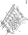
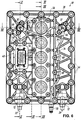
1 eine perspektivische Ansicht einer hydraulischen Betätigungsvorrichtung für die Betätigung von Stellgliedern in einem Kraftfahrzeuggetriebe nach einem bevorzugten Ausführungsbeispiel der Erfindung im nicht-montierten Zustand von schräg oben / vorne links mit Blick auf die von einer Flanschfläche der Betätigungsvorrichtung abgewandte Seite der Betätigungsvorrichtung, auf der insbesondere Steuereinrichtungen der Betätigungsvorrichtung angeordnet sind; -
2 eine perspektivische Ansicht der Betätigungsvorrichtung gemäß1 im nicht-montierten Zustand von schräg unten / vorne rechts mit Blick auf Kolben-Zylinder-Anordnungen und die Flanschfläche der Betätigungsvorrichtung, über die die Betätigungsvorrichtung an einer Trennwand eines Getriebegehäuses des Kraftfahrzeuggetriebes angeflanscht werden kann; -
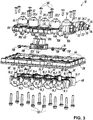
3 eine perspektivische Explosionsdarstellung der Betätigungsvorrichtung gemäß1 von schräg oben / vorne links zur besseren Veranschaulichung einer die Kolben-Zylinder-Anordnungen tragenden ersten Trägerplatte, einer die Steuereinrichtungen tragenden zweiten Trägerplatte und einer dazwischen angeordneten Platine als elektrische Verbindungseinheit zur elektrischen Kontaktierung und Ansteuerung der Steuereinrichtungen; -
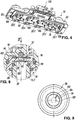
4 eine perspektivische Ansicht der zweiten Trägerplatte der Betätigungsvorrichtung gemäß1 von schräg unten / hinten links mit Blick auf die auf der Unterseite der zweiten Trägerplatte angebrachte Platine; -
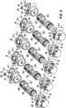
5 eine perspektivische Explosionsdarstellung der Kolben-Zylinder-Anordnungen der Betätigungsvorrichtung gemäß1 von schräg oben / hinten links zur besseren Veranschaulichung von Stellkolben und Zylindergehäusetypen der Kolben-Zylinder-Anordnungen; -
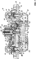
6 eine Draufsicht auf die Betätigungsvorrichtung gemäß1 von oben in1 ; -
7 eine im Maßstab gegenüber der6 vergrößerte Schnittansicht der Betätigungsvorrichtung gemäß1 entsprechend der SchnittverlaufslinieVII-VII in6 , wobei die Schnittansicht um 180° in der Zeichnungsebene gedreht wurde, um die Einbaulage der Betätigungsvorrichtung zu veranschaulichen; -
8 eine im Maßstab gegenüber der7 nochmals deutlich vergrößerte Schnittansicht der Betätigungsvorrichtung gemäß1 entsprechend dem DetailkreisVIII in7 zur besseren Illustration eines Entlüftungsventils der Betätigungsvorrichtung; -
9 eine Draufsicht auf einen Ventilsitz des Entlüftungsventils der Betätigungsvorrichtung gemäß1 mit Blickrichtung entsprechend dem PfeilIX in8 ; -
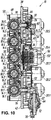
10 eine hinsichtlich des Maßstabs der6 entsprechende Schnittansicht der Betätigungsvorrichtung gemäß1 entsprechend der SchnittverlaufslinieX-X in6 ; -
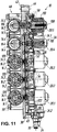
11 eine wiederum hinsichtlich des Maßstabs der6 entsprechende Schnittansicht der Betätigungsvorrichtung gemäß1 entsprechend der zweifach versetzten Schnittverlaufslinie XI-XI in6 ; -
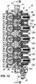
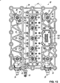
12 eine erneut hinsichtlich des Maßstabs der6 entsprechende Schnittansicht der Betätigungsvorrichtung gemäß1 entsprechend der SchnittverlaufslinieXII-XII in6 ; und -
13 eineim Maßstab der 12 entsprechende Schnittansicht der Betätigungsvorrichtung gemäß1 entsprechend der SchnittverlaufslinieXIII-XIII in12 .
-
1 a perspective view of a hydraulic actuating device for the actuation of actuators in a motor vehicle transmission according to a preferred embodiment of the invention in the non-assembled state from obliquely above / front left with a view of the side of the actuating device facing away from a flange surface of the actuating device, in particular on the control devices of the Actuator are arranged; -
2nd a perspective view of the actuator according to1 in the unassembled state from obliquely below / at the front right with a view of piston-cylinder arrangements and the flange surface of the actuating device, via which the actuating device can be flanged to a partition wall of a transmission housing of the motor vehicle transmission; -
3rd a perspective exploded view of the actuator according to1 from obliquely top / front left for better illustration of a first carrier plate carrying the piston-cylinder arrangements, a second carrier plate carrying the control devices and a circuit board arranged between them as an electrical connection unit for electrical contacting and control of the control devices; -
4th a perspective view of the second support plate of the actuator according to1 from obliquely below / behind left with a view of the circuit board attached to the underside of the second carrier plate; -
5 a perspective exploded view of the piston-cylinder arrangements of the actuator according to1 diagonally from top / rear left to better illustrate actuating pistons and cylinder housing types of piston-cylinder arrangements; -
6 a plan view of the actuator according to1 from above in1 ; -
7 one in scale against the6 enlarged sectional view of the actuator according to1 according to the cutting lineVII-VII in6 , wherein the sectional view has been rotated 180 ° in the plane of the drawing to illustrate the installation position of the actuating device; -
8th one in scale against the7 again clearly enlarged sectional view of the actuating device according to1 according to the detail circleVIII in7 for better illustration of a vent valve of the actuating device; -
9 a plan view of a valve seat of the vent valve of the actuator according to1 facing the arrowIX in8th ; -
10 one in terms of scale6 corresponding sectional view of the actuator according to1 according to the cutting lineXX in6 ; -
11 one again in terms of scale6 corresponding sectional view of the actuator according to1 corresponding to the twice offset cutting line XI-XI in6 ; -
12th one again in terms of scale6 corresponding sectional view of the actuator according to1 according to the cutting lineXII-XII in6 ; and -
13 one on a scale of12th corresponding sectional view of the actuator according to1 according to the cutting lineXIII-XIII in12th .
DETAILLIERTE BESCHREIBUNG DES AUSFÜHRUNGSBEISPIELSDETAILED DESCRIPTION OF THE EMBODIMENT
In den Figuren beziffert das Bezugszeichen
Im dargestellten Ausführungsbeispiel sind für ein automatisiertes LKW-Schaltgetriebe (ASG) mit acht Vorwärtsgängen und zwei Rückwärtsgängen insgesamt fünf Kolben-Zylinder-Anordnungen
Jeder Kolben-Zylinder-Anordnung
Wie im Folgenden noch im Einzelnen erläutert wird, bestehen im Vergleich zum eingangs geschilderten Stand der Technik verschiedene Besonderheiten der Betätigungsvorrichtung
Zum anderen (ii) ist eine elektrische Verbindungseinheit - hier in der Form einer Platine
Wie die
Die
Die einzelnen Steuereinrichtungen
Gemäß den
Komplettiert wird der hydraulische Teil der Betätigungsvorrichtung
In den
Gemäß den
Weitere Details der Zylinderbaugruppe
Bei der Reihenanordnung von Zylindergehäusen
Zur Positionierung der Zylindergehäuse
Wie die
Details zu den Entlüftungsventilen
In
Für den Fachmann ist insoweit ersichtlich, dass die Verbindungsnut
Zur Unterstützung der so bewirkten Entlüftung des hydraulischen Systems können im Übrigen die Stellkolben
Weitere Details zu den identisch ausgebildeten Steuereinrichtungen
Demgemäß handelt es sich bei den Steuereinrichtungen
In an sich bekannter Weise kann das Sperrelement
Des Weiteren ist jeder Kolben-Zylinder-Anordnung
Wie die
Insbesondere in den
Gemäß den
Wie in den
Was im Übrigen die Funktionsweise der vorbeschriebenen Betätigungsvorrichtung
Eine hydraulische Betätigungsvorrichtung für die Betätigung von Stellgliedern in einem Kraftfahrzeuggetriebe hat eine Mehrzahl von Kolben-Zylinder-Anordnungen, deren Stellkolben jeweils mit einem Stellglied wirkverbindbar sind, um eine Stellbewegung des Stellglieds zu erzeugen. Ferner ist eine Mehrzahl von elektrisch betätigbaren Steuereinrichtungen vorgesehen, die jeweils einer Kolben-Zylinder-Anordnung zugeordnet sind und dazu dienen, die Stellbewegung des jeweiligen Stellglieds zu gestatten oder zu unterbinden. Eine elektrische Verbindungseinheit sorgt für die elektrische Kontaktierung und Ansteuerung der Steuereinrichtungen. Während die Kolben-Zylinder-Anordnungen auf einer ersten Trägerplatte montiert sind, sind die Steuereinrichtungen auf einer zweiten Trägerplatte befestigt, die mit der ersten Trägerplatte verbunden ist. Zum Schutz der elektrischen Verbindungseinheit ist diese in sehr kompakter Bauweise zwischen der ersten Trägerplatte und der zweiten Trägerplatte angeordnet.A hydraulic actuating device for actuating actuators in a motor vehicle transmission has a plurality of piston-cylinder arrangements, the actuating pistons of which can each be operatively connected to an actuator in order to generate an actuating movement of the actuator. Furthermore, a plurality of electrically actuable control devices are provided, each of which is assigned to a piston-cylinder arrangement and is used to allow or prevent the actuating movement of the respective actuator. An electrical connection unit ensures electrical contacting and control of the control devices. While the piston-cylinder arrangements are mounted on a first carrier plate, the control devices are fastened on a second carrier plate which is connected to the first carrier plate. To protect the electrical connection unit, it is arranged in a very compact design between the first carrier plate and the second carrier plate.
BezugszeichenlisteReference list
- 1010th
- BetätigungsvorrichtungActuator
- 1212th
- StellgliedActuator
- 14.114.1
- Kolben-Zylinder-AnordnungPiston-cylinder arrangement
- 14.214.2
- Kolben-Zylinder-AnordnungPiston-cylinder arrangement
- 14.314.3
- Kolben-Zylinder-AnordnungPiston-cylinder arrangement
- 14.414.4
- Kolben-Zylinder-AnordnungPiston-cylinder arrangement
- 14.514.5
- Kolben-Zylinder-AnordnungPiston-cylinder arrangement
- 16.116.1
- StellkolbenAdjusting piston
- 16.216.2
- StellkolbenAdjusting piston
- 16.316.3
- StellkolbenAdjusting piston
- 16.416.4
- StellkolbenAdjusting piston
- 16.516.5
- StellkolbenAdjusting piston
- 18.1, 18.1'18.1, 18.1 '
- DruckraumPressure room
- 18.2, 18.2'18.2, 18.2 '
- DruckraumPressure room
- 18.3, 18.3'18.3, 18.3 '
- DruckraumPressure room
- 18.4, 18.4'18.4, 18.4 '
- DruckraumPressure room
- 18.5, 18.5' 18.5, 18.5 '
- DruckraumPressure room
- 20.120.1
- SteuereinrichtungControl device
- 20.220.2
- SteuereinrichtungControl device
- 20.320.3
- SteuereinrichtungControl device
- 20.420.4
- SteuereinrichtungControl device
- 20.520.5
- SteuereinrichtungControl device
- 2222
- erste Druckleitungfirst pressure line
- 2424th
- zweite Druckleitungsecond pressure line
- 2626
- EntlüftungsventilVent valve
- 2828
- EntlüftungsventilVent valve
- 3030th
- AbgangFinish
- 3232
- AbgangFinish
- 3434
- EntlüftungsleitungVent line
- 34.134.1
- LeitungsabschnittLine section
- 34.234.2
- LeitungsabschnittLine section
- 3636
- Platinecircuit board
- 3838
- erste Trägerplattefirst carrier plate
- 4040
- zweite Trägerplattesecond carrier plate
- 4242
- FlanschflächeFlange surface
- 4444
- BefestigungslochMounting hole
- 4646
- ZentrierhülseCentering sleeve
- 4848
- ZylinderbaugruppeCylinder assembly
- 5050
- BefestigungsschraubeMounting screw
- 5252
- HalteplatteRetaining plate
- 5454
- BefestigungsschraubeMounting screw
- 5656
- SteuerbaugruppeControl module
- 5858
- BefestigungsschraubeMounting screw
- 6060
- ZentrierfortsatzCentering process
- 6262
- ZentrieraussparungCentering recess
- 6464
- AnschlussgehäuseJunction box
- 6666
- VentilgehäuseValve body
- 6868
- Halterholder
- 7070
- SteckanschlussPlug-in connection
- 7272
- SteckanschlussPlug-in connection
- 74.1, 74.1'74.1, 74.1 '
- ZylindergehäuseCylinder housing
- 74.2, 74.2'74.2, 74.2 '
- ZylindergehäuseCylinder housing
- 74.3, 74.3'74.3, 74.3 '
- ZylindergehäuseCylinder housing
- 74.4, 74.4'74.4, 74.4 '
- ZylindergehäuseCylinder housing
- 74.5, 74.5'74.5, 74.5 '
- ZylindergehäuseCylinder housing
- 76, 76'76, 76 '
- HydraulikeingangHydraulic input
- 78, 78'78, 78 '
- HydraulikausgangHydraulic outlet
- 80, 80'80, 80 '
- EingangsanschlussInput connector
- 82, 82'82, 82 '
- EndanschlussEnd connection
- 8484
- PositioniervorsprungPositioning projection
- 8686
- PositionieraussparungPositioning recess
- 8888
- Öffnungopening
- 9090
- AnschlagleisteStop bar
- 9292
- VentilkörperValve body
- 9494
- VentilsitzValve seat
- 9696
- EinsatzteilInsert part
- 9898
- O-RingO-ring
- 100100
- DurchgangContinuity
- 102102
- RingnutRing groove
- 104104
- VerbindungsnutConnecting groove
- 106106
- SperrelementLocking element
- 108108
- Federfeather
- 110110
- AktuatorActuator
- 112112
- ZustellachseInfeed axis
- 113113
- Öffnungopening
- 114114
- AussparungRecess
- 116116
- SensoranordnungSensor arrangement
- 118118
- PositionsdetektorPosition detector
- 120120
- PositionsgeberPosition transmitter
- 122122
- AussparungRecess
- 124124
- BefestigungsschraubeMounting screw
- 126126
- DichtungsanordnungSealing arrangement
- 128128
- KontaktstiftContact pin
- 130130
- elektrische Schnittstelleelectrical interface
- 132132
- SteckanschlussPlug-in connection
- 134134
- KontaktstiftContact pin
ZITATE ENTHALTEN IN DER BESCHREIBUNG QUOTES INCLUDE IN THE DESCRIPTION
Diese Liste der vom Anmelder aufgeführten Dokumente wurde automatisiert erzeugt und ist ausschließlich zur besseren Information des Lesers aufgenommen. Die Liste ist nicht Bestandteil der deutschen Patent- bzw. Gebrauchsmusteranmeldung. Das DPMA übernimmt keinerlei Haftung für etwaige Fehler oder Auslassungen.This list of documents listed by the applicant has been generated automatically and is only included for the better information of the reader. The list is not part of the German patent or utility model application. The DPMA assumes no liability for any errors or omissions.
Zitierte PatentliteraturPatent literature cited
- US 2006/0005647 A1 [0003]US 2006/0005647 A1 [0003]
- DE 102018008943 [0048]DE 102018008943 [0048]
- EP 2543891 A2 [0049]EP 2543891 A2 [0049]
- EP 2754911 A1 [0057]EP 2754911 A1 [0057]
Claims (15)
Priority Applications (3)
| Application Number | Priority Date | Filing Date | Title |
|---|---|---|---|
| DE102018009853.3A DE102018009853B4 (en) | 2018-12-19 | 2018-12-19 | Hydraulic actuator for operating actuators in a motor vehicle transmission |
| CN201911301082.2A CN111336244B (en) | 2018-12-19 | 2019-12-17 | Hydraulic operating device for operating an actuating element in a motor vehicle transmission |
| KR1020190169814A KR102857441B1 (en) | 2018-12-19 | 2019-12-18 | Hydraulic operating apparatus for the operation of actuating elements in a motor vehicle transmission |
Applications Claiming Priority (1)
| Application Number | Priority Date | Filing Date | Title |
|---|---|---|---|
| DE102018009853.3A DE102018009853B4 (en) | 2018-12-19 | 2018-12-19 | Hydraulic actuator for operating actuators in a motor vehicle transmission |
Publications (2)
| Publication Number | Publication Date |
|---|---|
| DE102018009853A1 true DE102018009853A1 (en) | 2020-06-25 |
| DE102018009853B4 DE102018009853B4 (en) | 2022-12-01 |
Family
ID=70969062
Family Applications (1)
| Application Number | Title | Priority Date | Filing Date |
|---|---|---|---|
| DE102018009853.3A Active DE102018009853B4 (en) | 2018-12-19 | 2018-12-19 | Hydraulic actuator for operating actuators in a motor vehicle transmission |
Country Status (3)
| Country | Link |
|---|---|
| KR (1) | KR102857441B1 (en) |
| CN (1) | CN111336244B (en) |
| DE (1) | DE102018009853B4 (en) |
Cited By (2)
| Publication number | Priority date | Publication date | Assignee | Title |
|---|---|---|---|---|
| EP3957885A1 (en) * | 2020-08-20 | 2022-02-23 | Robert Bosch GmbH | Electrically actuated valve |
| US12529422B2 (en) * | 2021-12-14 | 2026-01-20 | Valeo Powertrain Gmbh | Gear-change selector module for a gearshift |
Citations (6)
| Publication number | Priority date | Publication date | Assignee | Title |
|---|---|---|---|---|
| DE3621031A1 (en) * | 1985-08-29 | 1987-03-12 | Kubota Ltd | HYDRAULIC CONSTRUCTION FOR A COMMERCIAL VEHICLE |
| US20060005647A1 (en) | 2004-07-09 | 2006-01-12 | Braford Thomas E | Integrated control module for a dual clutch transmission |
| EP2543891A2 (en) | 2011-07-06 | 2013-01-09 | FTE automotive GmbH & Co. KG | Hydraulic actuation device for actuating one or more positioning members, particularly in motor vehicles |
| EP2754911A1 (en) | 2013-01-09 | 2014-07-16 | FTE automotive GmbH | Hydraulic actuation device for actuating at least a friction clutch transmission and at least one gear actuator in a motor vehicle |
| DE202015102095U1 (en) * | 2015-04-27 | 2016-08-01 | Bürkert Werke GmbH | Valve actuator, actuator system and valve |
| DE102018008943A1 (en) | 2018-11-14 | 2020-05-14 | Fte Automotive Gmbh | Method for venting a device for the hydraulic actuation of at least one friction clutch and / or at least one transmission actuator |
Family Cites Families (5)
| Publication number | Priority date | Publication date | Assignee | Title |
|---|---|---|---|---|
| US6929031B2 (en) * | 2003-03-28 | 2005-08-16 | Eaton Corporation | Electro-hydraulic manifold assembly with lead frame mounted pressure sensors |
| DE102007062147B4 (en) * | 2007-12-21 | 2009-09-10 | Dr. Ing. H.C. F. Porsche Aktiengesellschaft | Hydraulic control device of a clutch of a motor vehicle |
| JP5365552B2 (en) * | 2010-03-09 | 2013-12-11 | マツダ株式会社 | Control device for automatic transmission |
| EP2381137A1 (en) * | 2010-04-21 | 2011-10-26 | C.R.F. Società Consortile per Azioni | Electro-hydraulic group for an automotive servo-assisted mechanical transmission |
| DE102014011177A1 (en) * | 2014-07-31 | 2016-02-04 | Fte Automotive Gmbh | Hydraulic or pneumatic actuator for actuating actuators in a motor vehicle transmission |
-
2018
- 2018-12-19 DE DE102018009853.3A patent/DE102018009853B4/en active Active
-
2019
- 2019-12-17 CN CN201911301082.2A patent/CN111336244B/en active Active
- 2019-12-18 KR KR1020190169814A patent/KR102857441B1/en active Active
Patent Citations (6)
| Publication number | Priority date | Publication date | Assignee | Title |
|---|---|---|---|---|
| DE3621031A1 (en) * | 1985-08-29 | 1987-03-12 | Kubota Ltd | HYDRAULIC CONSTRUCTION FOR A COMMERCIAL VEHICLE |
| US20060005647A1 (en) | 2004-07-09 | 2006-01-12 | Braford Thomas E | Integrated control module for a dual clutch transmission |
| EP2543891A2 (en) | 2011-07-06 | 2013-01-09 | FTE automotive GmbH & Co. KG | Hydraulic actuation device for actuating one or more positioning members, particularly in motor vehicles |
| EP2754911A1 (en) | 2013-01-09 | 2014-07-16 | FTE automotive GmbH | Hydraulic actuation device for actuating at least a friction clutch transmission and at least one gear actuator in a motor vehicle |
| DE202015102095U1 (en) * | 2015-04-27 | 2016-08-01 | Bürkert Werke GmbH | Valve actuator, actuator system and valve |
| DE102018008943A1 (en) | 2018-11-14 | 2020-05-14 | Fte Automotive Gmbh | Method for venting a device for the hydraulic actuation of at least one friction clutch and / or at least one transmission actuator |
Cited By (3)
| Publication number | Priority date | Publication date | Assignee | Title |
|---|---|---|---|---|
| EP3957885A1 (en) * | 2020-08-20 | 2022-02-23 | Robert Bosch GmbH | Electrically actuated valve |
| US11566720B2 (en) | 2020-08-20 | 2023-01-31 | Robert Bosch Gmbh | Electrically actuated valve |
| US12529422B2 (en) * | 2021-12-14 | 2026-01-20 | Valeo Powertrain Gmbh | Gear-change selector module for a gearshift |
Also Published As
| Publication number | Publication date |
|---|---|
| DE102018009853B4 (en) | 2022-12-01 |
| KR20200076640A (en) | 2020-06-29 |
| KR102857441B1 (en) | 2025-09-09 |
| CN111336244A (en) | 2020-06-26 |
| CN111336244B (en) | 2022-10-21 |
Similar Documents
| Publication | Publication Date | Title |
|---|---|---|
| EP3175150B1 (en) | Hydraulic or pneumatic operating device for operating actuators in a motor vehicle transmission | |
| EP3082406B1 (en) | Safety valve | |
| DE102018006098A1 (en) | Parking lock module for actuating a parking lock in a motor vehicle | |
| EP3186119B1 (en) | Valve unit for modulating pressure in an air-brake system | |
| DE19537482A1 (en) | Hydraulic control block | |
| EP3390177B1 (en) | Valve unit for modulating the pressure in a pneumatic brake system | |
| EP0687606A2 (en) | Hydraulic unit for antilock brake systems | |
| DE102014207509A1 (en) | Integrated air supply unit | |
| WO2010057560A1 (en) | Valve and assembly method | |
| EP3186118B1 (en) | Valve unit for modulating the pressure in a pneumatic brake system | |
| DE102014009179A1 (en) | valve assembly | |
| DE69704592T2 (en) | Pilot operated selector valve | |
| DE102017118260A1 (en) | Valve and valve assembly | |
| DE102017108030A1 (en) | Switching module of an automatic gearbox | |
| DE102005015481A1 (en) | Switching device of an automated transmission of a motor vehicle | |
| DE102018009853B4 (en) | Hydraulic actuator for operating actuators in a motor vehicle transmission | |
| DE102015115082B4 (en) | Valve unit for pneumatic applications as well as air suspension system | |
| DE102014012596A1 (en) | Valve unit for pressure modulation in a compressed air brake system | |
| DE102018009852A1 (en) | Hydraulic actuating device for actuating actuators in a motor vehicle transmission | |
| DE102011116632A1 (en) | Valve, hydraulic arrangement with such a valve and use of a button or switch for a valve | |
| DE102012001100A1 (en) | Arrangement for controlling a double-acting switching cylinder of a Schaltanord-tion of an automated transmission of a motor vehicle | |
| EP0686775B1 (en) | Electropneumatic valve assembly | |
| DE102022211646A1 (en) | Brake actuation device for a motor vehicle brake system with an adapter device | |
| DE102008003241A1 (en) | Hydraulic switching device | |
| DE102018006093B4 (en) | Parking lock module for actuating a parking lock in a motor vehicle |
Legal Events
| Date | Code | Title | Description |
|---|---|---|---|
| R163 | Identified publications notified | ||
| R012 | Request for examination validly filed | ||
| R018 | Grant decision by examination section/examining division | ||
| R020 | Patent grant now final | ||
| R081 | Change of applicant/patentee |
Owner name: VALEO POWERTRAIN GMBH, DE Free format text: FORMER OWNER: FTE ASIA GMBH, 96106 EBERN, DE Owner name: VALEO POWERTRAIN GMBH, DE Free format text: FORMER OWNER: FTE AUTOMOTIVE GMBH, 96106 EBERN, DE |