DE102018009852A1 - Hydraulic actuating device for actuating actuators in a motor vehicle transmission - Google Patents
Hydraulic actuating device for actuating actuators in a motor vehicle transmission Download PDFInfo
- Publication number
- DE102018009852A1 DE102018009852A1 DE102018009852.5A DE102018009852A DE102018009852A1 DE 102018009852 A1 DE102018009852 A1 DE 102018009852A1 DE 102018009852 A DE102018009852 A DE 102018009852A DE 102018009852 A1 DE102018009852 A1 DE 102018009852A1
- Authority
- DE
- Germany
- Prior art keywords
- piston
- hydraulic
- actuating
- cylinder
- line
- Prior art date
- Legal status (The legal status is an assumption and is not a legal conclusion. Google has not performed a legal analysis and makes no representation as to the accuracy of the status listed.)
- Withdrawn
Links
- 230000005540 biological transmission Effects 0.000 title claims abstract description 29
- 238000009423 ventilation Methods 0.000 claims description 29
- 230000000903 blocking effect Effects 0.000 claims description 3
- 239000013013 elastic material Substances 0.000 claims description 3
- 238000013022 venting Methods 0.000 abstract description 5
- 239000012530 fluid Substances 0.000 description 8
- 238000007789 sealing Methods 0.000 description 6
- 238000011982 device technology Methods 0.000 description 4
- 230000000712 assembly Effects 0.000 description 3
- 238000000429 assembly Methods 0.000 description 3
- 230000008901 benefit Effects 0.000 description 3
- 238000013461 design Methods 0.000 description 3
- 230000000694 effects Effects 0.000 description 3
- 238000009434 installation Methods 0.000 description 3
- 238000000034 method Methods 0.000 description 3
- 230000008569 process Effects 0.000 description 3
- 238000002347 injection Methods 0.000 description 2
- 239000007924 injection Substances 0.000 description 2
- 238000012423 maintenance Methods 0.000 description 2
- BASFCYQUMIYNBI-UHFFFAOYSA-N platinum Chemical compound [Pt] BASFCYQUMIYNBI-UHFFFAOYSA-N 0.000 description 2
- 230000036316 preload Effects 0.000 description 2
- 238000005086 pumping Methods 0.000 description 2
- BUHVIAUBTBOHAG-FOYDDCNASA-N (2r,3r,4s,5r)-2-[6-[[2-(3,5-dimethoxyphenyl)-2-(2-methylphenyl)ethyl]amino]purin-9-yl]-5-(hydroxymethyl)oxolane-3,4-diol Chemical compound COC1=CC(OC)=CC(C(CNC=2C=3N=CN(C=3N=CN=2)[C@H]2[C@@H]([C@H](O)[C@@H](CO)O2)O)C=2C(=CC=CC=2)C)=C1 BUHVIAUBTBOHAG-FOYDDCNASA-N 0.000 description 1
- TVEXGJYMHHTVKP-UHFFFAOYSA-N 6-oxabicyclo[3.2.1]oct-3-en-7-one Chemical compound C1C2C(=O)OC1C=CC2 TVEXGJYMHHTVKP-UHFFFAOYSA-N 0.000 description 1
- 239000011324 bead Substances 0.000 description 1
- 230000008878 coupling Effects 0.000 description 1
- 238000010168 coupling process Methods 0.000 description 1
- 238000005859 coupling reaction Methods 0.000 description 1
- 230000001419 dependent effect Effects 0.000 description 1
- 238000011161 development Methods 0.000 description 1
- 210000003746 feather Anatomy 0.000 description 1
- 238000004519 manufacturing process Methods 0.000 description 1
- 239000000463 material Substances 0.000 description 1
- 229910001092 metal group alloy Inorganic materials 0.000 description 1
- 239000000203 mixture Substances 0.000 description 1
- 230000007935 neutral effect Effects 0.000 description 1
- 238000005192 partition Methods 0.000 description 1
- 230000009467 reduction Effects 0.000 description 1
- 230000008439 repair process Effects 0.000 description 1
Images
Classifications
-
- F—MECHANICAL ENGINEERING; LIGHTING; HEATING; WEAPONS; BLASTING
- F16—ENGINEERING ELEMENTS AND UNITS; GENERAL MEASURES FOR PRODUCING AND MAINTAINING EFFECTIVE FUNCTIONING OF MACHINES OR INSTALLATIONS; THERMAL INSULATION IN GENERAL
- F16H—GEARING
- F16H61/00—Control functions within control units of change-speed- or reversing-gearings for conveying rotary motion ; Control of exclusively fluid gearing, friction gearing, gearings with endless flexible members or other particular types of gearing
- F16H61/26—Generation or transmission of movements for final actuating mechanisms
- F16H61/28—Generation or transmission of movements for final actuating mechanisms with at least one movement of the final actuating mechanism being caused by a non-mechanical force, e.g. power-assisted
- F16H61/30—Hydraulic or pneumatic motors or related fluid control means therefor
-
- F—MECHANICAL ENGINEERING; LIGHTING; HEATING; WEAPONS; BLASTING
- F16—ENGINEERING ELEMENTS AND UNITS; GENERAL MEASURES FOR PRODUCING AND MAINTAINING EFFECTIVE FUNCTIONING OF MACHINES OR INSTALLATIONS; THERMAL INSULATION IN GENERAL
- F16D—COUPLINGS FOR TRANSMITTING ROTATION; CLUTCHES; BRAKES
- F16D48/00—External control of clutches
- F16D48/02—Control by fluid pressure
-
- F—MECHANICAL ENGINEERING; LIGHTING; HEATING; WEAPONS; BLASTING
- F16—ENGINEERING ELEMENTS AND UNITS; GENERAL MEASURES FOR PRODUCING AND MAINTAINING EFFECTIVE FUNCTIONING OF MACHINES OR INSTALLATIONS; THERMAL INSULATION IN GENERAL
- F16H—GEARING
- F16H59/00—Control inputs to control units of change-speed- or reversing-gearings for conveying rotary motion
- F16H59/02—Selector apparatus
- F16H59/0204—Selector apparatus for automatic transmissions with means for range selection and manual shifting, e.g. range selector with tiptronic
-
- F—MECHANICAL ENGINEERING; LIGHTING; HEATING; WEAPONS; BLASTING
- F16—ENGINEERING ELEMENTS AND UNITS; GENERAL MEASURES FOR PRODUCING AND MAINTAINING EFFECTIVE FUNCTIONING OF MACHINES OR INSTALLATIONS; THERMAL INSULATION IN GENERAL
- F16H—GEARING
- F16H63/00—Control outputs from the control unit to change-speed- or reversing-gearings for conveying rotary motion or to other devices than the final output mechanism
- F16H63/02—Final output mechanisms therefor; Actuating means for the final output mechanisms
- F16H63/24—Final output mechanisms therefor; Actuating means for the final output mechanisms each of the final output mechanisms being moved by only one of the various final actuating mechanisms
-
- F—MECHANICAL ENGINEERING; LIGHTING; HEATING; WEAPONS; BLASTING
- F16—ENGINEERING ELEMENTS AND UNITS; GENERAL MEASURES FOR PRODUCING AND MAINTAINING EFFECTIVE FUNCTIONING OF MACHINES OR INSTALLATIONS; THERMAL INSULATION IN GENERAL
- F16H—GEARING
- F16H63/00—Control outputs from the control unit to change-speed- or reversing-gearings for conveying rotary motion or to other devices than the final output mechanism
- F16H63/02—Final output mechanisms therefor; Actuating means for the final output mechanisms
- F16H63/30—Constructional features of the final output mechanisms
- F16H63/3023—Constructional features of the final output mechanisms the final output mechanisms comprising elements moved by fluid pressure
-
- F—MECHANICAL ENGINEERING; LIGHTING; HEATING; WEAPONS; BLASTING
- F16—ENGINEERING ELEMENTS AND UNITS; GENERAL MEASURES FOR PRODUCING AND MAINTAINING EFFECTIVE FUNCTIONING OF MACHINES OR INSTALLATIONS; THERMAL INSULATION IN GENERAL
- F16H—GEARING
- F16H63/00—Control outputs from the control unit to change-speed- or reversing-gearings for conveying rotary motion or to other devices than the final output mechanism
- F16H63/02—Final output mechanisms therefor; Actuating means for the final output mechanisms
- F16H63/30—Constructional features of the final output mechanisms
- F16H63/34—Locking or disabling mechanisms
-
- F—MECHANICAL ENGINEERING; LIGHTING; HEATING; WEAPONS; BLASTING
- F16—ENGINEERING ELEMENTS AND UNITS; GENERAL MEASURES FOR PRODUCING AND MAINTAINING EFFECTIVE FUNCTIONING OF MACHINES OR INSTALLATIONS; THERMAL INSULATION IN GENERAL
- F16D—COUPLINGS FOR TRANSMITTING ROTATION; CLUTCHES; BRAKES
- F16D48/00—External control of clutches
- F16D48/02—Control by fluid pressure
- F16D2048/0209—Control by fluid pressure characterised by fluid valves having control pistons, e.g. spools
-
- F—MECHANICAL ENGINEERING; LIGHTING; HEATING; WEAPONS; BLASTING
- F16—ENGINEERING ELEMENTS AND UNITS; GENERAL MEASURES FOR PRODUCING AND MAINTAINING EFFECTIVE FUNCTIONING OF MACHINES OR INSTALLATIONS; THERMAL INSULATION IN GENERAL
- F16D—COUPLINGS FOR TRANSMITTING ROTATION; CLUTCHES; BRAKES
- F16D48/00—External control of clutches
- F16D48/02—Control by fluid pressure
- F16D2048/0221—Valves for clutch control systems; Details thereof
-
- F—MECHANICAL ENGINEERING; LIGHTING; HEATING; WEAPONS; BLASTING
- F16—ENGINEERING ELEMENTS AND UNITS; GENERAL MEASURES FOR PRODUCING AND MAINTAINING EFFECTIVE FUNCTIONING OF MACHINES OR INSTALLATIONS; THERMAL INSULATION IN GENERAL
- F16H—GEARING
- F16H61/00—Control functions within control units of change-speed- or reversing-gearings for conveying rotary motion ; Control of exclusively fluid gearing, friction gearing, gearings with endless flexible members or other particular types of gearing
- F16H2061/004—Venting trapped air from hydraulic systems
-
- F—MECHANICAL ENGINEERING; LIGHTING; HEATING; WEAPONS; BLASTING
- F16—ENGINEERING ELEMENTS AND UNITS; GENERAL MEASURES FOR PRODUCING AND MAINTAINING EFFECTIVE FUNCTIONING OF MACHINES OR INSTALLATIONS; THERMAL INSULATION IN GENERAL
- F16H—GEARING
- F16H61/00—Control functions within control units of change-speed- or reversing-gearings for conveying rotary motion ; Control of exclusively fluid gearing, friction gearing, gearings with endless flexible members or other particular types of gearing
- F16H61/26—Generation or transmission of movements for final actuating mechanisms
- F16H61/28—Generation or transmission of movements for final actuating mechanisms with at least one movement of the final actuating mechanism being caused by a non-mechanical force, e.g. power-assisted
- F16H61/30—Hydraulic or pneumatic motors or related fluid control means therefor
- F16H2061/307—Actuators with three or more defined positions, e.g. three position servos
-
- F—MECHANICAL ENGINEERING; LIGHTING; HEATING; WEAPONS; BLASTING
- F16—ENGINEERING ELEMENTS AND UNITS; GENERAL MEASURES FOR PRODUCING AND MAINTAINING EFFECTIVE FUNCTIONING OF MACHINES OR INSTALLATIONS; THERMAL INSULATION IN GENERAL
- F16H—GEARING
- F16H61/00—Control functions within control units of change-speed- or reversing-gearings for conveying rotary motion ; Control of exclusively fluid gearing, friction gearing, gearings with endless flexible members or other particular types of gearing
- F16H61/26—Generation or transmission of movements for final actuating mechanisms
- F16H61/28—Generation or transmission of movements for final actuating mechanisms with at least one movement of the final actuating mechanism being caused by a non-mechanical force, e.g. power-assisted
- F16H61/30—Hydraulic or pneumatic motors or related fluid control means therefor
- F16H2061/308—Modular hydraulic shift units, i.e. preassembled actuator units for select and shift movements adapted for being mounted on transmission casing
Landscapes
- Engineering & Computer Science (AREA)
- General Engineering & Computer Science (AREA)
- Mechanical Engineering (AREA)
- Physics & Mathematics (AREA)
- Fluid Mechanics (AREA)
- Actuator (AREA)
- Gear-Shifting Mechanisms (AREA)
- Hydraulic Clutches, Magnetic Clutches, Fluid Clutches, And Fluid Joints (AREA)
Abstract
Eine hydraulische Betätigungsvorrichtung (10) für die Betätigung von Stellgliedern in einem Kraftfahrzeuggetriebe hat eine Mehrzahl von Kolben-Zylinder-Anordnungen (14.5), die jeweils einen mit einem Stellglied wirkverbindbaren Stellkolben (16.5) aufweisen, der auf einer ersten Seite und einer zweiten Seite über jeweils einen zugeordneten Druckraum (18.5, 18.5') hydraulisch beaufschlagt werden kann. Jeder Kolben-Zylinder-Anordnung ist eine Steuereinrichtung (20.5) zugeordnet, die eine Stellbewegung des jeweiligen Stellkolbens in einer ersten Richtung oder einer entgegengesetzten zweiten Richtung gestattet oder unterbindet. Ferner sind die Druckräume auf der ersten Seite der Stellkolben über eine gemeinsame erste Druckleitung (22) hydraulisch miteinander verbunden, während die Druckräume auf der zweiten Seite der Stellkolben über eine gemeinsame zweite Druckleitung (24) hydraulisch miteinander verbunden sind. Für eine einfache Entlüftung des Systems ist jeder Druckleitung wenigstens ein Entlüftungsventil (26, 28) mit einem Abgang (30, 32) für Luft zugeordnet, wobei die Abgänge der Entlüftungsventile an eine gemeinsame Entlüftungsleitung (34) angeschlossen sind.A hydraulic actuating device (10) for actuating actuators in a motor vehicle transmission has a plurality of piston-cylinder arrangements (14.5), each of which has an actuating piston (16.5) which can be operatively connected to an actuator and which on a first side and a second side an assigned pressure chamber (18.5, 18.5 ') can be acted upon hydraulically. A control device (20.5) is assigned to each piston-cylinder arrangement, which permits or prevents an actuating movement of the respective actuating piston in a first direction or an opposite second direction. Furthermore, the pressure spaces on the first side of the actuating pistons are hydraulically connected to one another via a common first pressure line (22), while the pressure spaces on the second side of the actuating pistons are hydraulically connected to one another via a common second pressure line (24). At least one vent valve (26, 28) with an outlet (30, 32) for air is assigned to each pressure line for a simple venting of the system, the outlets of the vent valves being connected to a common vent line (34).
Description
TECHNISCHES GEBIETTECHNICAL AREA
Die vorliegende Erfindung bezieht sich auf eine hydraulische Betätigungsvorrichtung für die Betätigung von Stellgliedern in einem Kraftfahrzeuggetriebe gemäß dem Oberbegriff des Patentanspruchs 1.The present invention relates to a hydraulic actuating device for actuating actuators in a motor vehicle transmission according to the preamble of patent claim 1.
Derartige Betätigungsvorrichtungen kommen auch in modernen Nutzfahrzeugen, wie LKW und Bussen, massenweise zum Einsatz, wenn es gilt, in automatisierten Schaltgetrieben (ASG), Doppel- oder Mehrkupplungsgetrieben (DKG) oder trennbaren Verteiler- und Differentialgetrieben Getriebestellglieder, wie Schaltgabeln und Schaltmuffen, mit oder ohne Synchronisiereinrichtung, und ggf. Trocken- oder Nass-Reibkupplungen möglichst flexibel und reibungsarm sowie mit geringem Bauraumbedarf zu betätigen.Actuators of this type are also used in large numbers in modern commercial vehicles, such as trucks and buses, when it matters, in automated manual transmissions (ASG), double or multiple clutch transmissions (DKG) or separable distributor and differential gears, transmission actuators, such as shift forks and shift sleeves, with or to operate without synchronization, and if necessary dry or wet friction clutches as flexible and low-friction as possible and with little space requirement.
STAND DER TECHNIKSTATE OF THE ART
Aus der den Oberbegriff des Patentanspruchs 1 bildenden Drucke schrift
Bei diesem Stand der Technik sind des Weiteren die Kolben der Stellzylinder auf gegenüberliegenden Seiten hydraulisch beaufschlagbar, wobei jedem Kolben als Steuerglied eine eigene Rastiereinrichtung mit einem Sperrelement funktional zugeordnet ist. Das Sperrelement jeder Rastiereinrichtung ist in eine Sperrstellung federvorgespannt, in der das Sperrelement eine Bewegung des jeweiligen Kolbens verhindert, und kann mittels eines über das Steuergerät elektrisch ansteuerbaren Aktuators der entsprechenden Rastiereinrichtung von der Sperrstellung gegen die Federvorspannung in eine Lösestellung bewegt werden, in der das Sperrelement eine Bewegung des jeweiligen Kolbens zulässt. Dabei ist die Drehrichtung des Pumpenantriebs und damit die Pumprichtung der Pumpe in der Leistungseinheit umkehrbar, um die Kolben der Stellzylinder für eine Betätigungs- bzw. Stellbewegung je nach Pumprichtung auf der einen oder der anderen Seite hydraulisch zu beaufschlagen. Das Steuergerät koordiniert hierbei die elektrische Ansteuerung des Pumpenantriebs und der Aktuatoren der Rastiereinrichtungen, um die angeschlossenen Getriebestellglieder zu betätigen bzw. die Reibkupplung aus- oder einzurücken.In this prior art, the pistons of the actuating cylinders can also be acted upon hydraulically on opposite sides, each piston being functionally assigned its own locking device with a locking element as a control element. The locking element of each locking device is spring-biased into a locking position, in which the locking element prevents movement of the respective piston, and can be moved from the locking position against the spring preload into a release position, in which the locking element, by means of an actuator of the corresponding locking device that can be electrically controlled via the control unit allows movement of the respective piston. The direction of rotation of the pump drive and thus the pumping direction of the pump in the power unit can be reversed in order to act hydraulically on one side or the other on the pistons of the actuating cylinders for an actuating or adjusting movement depending on the pumping direction. The control unit coordinates the electrical control of the pump drive and the actuators of the locking devices in order to actuate the connected transmission actuator elements or to disengage or engage the friction clutch.
Bei einer solchen Betätigungsvorrichtung werden also mehrere Stellzylinder eingesetzt, die über Druckkreise, welche zumeist aus frei verlegbaren Rohr- und/oder Schlauchleitungen bestehen, mit der Leistungseinheit, d.h. dem Druckerzeuger verbunden sind. Da Hydraulikflüssigkeiten (wie im vorliegenden Fall z.B. Öl oder Bremsflüssigkeit) inkompressibel sind, hat der im jeweiligen Druckkreis auf die Hydraulikflüssigkeit wirkende Druck keinen Einfluss auf ihr Volumen und somit auf das Übertragungsverhalten der Hydraulikflüssigkeit im Druckkreis. Im Ergebnis lassen sich über die Hydraulikflüssigkeit im jeweiligen Druckkreis auch hohe Kräfte gleichförmig übertragen, so dass mittels der mit dem jeweiligen Druckkreis hydraulisch verbundenen Stellzylinder exakte Stellbewegungen für die Kuppel- und Schaltvorgänge bewirkt werden können.In the case of such an actuating device, several actuating cylinders are thus used, which are connected to the power unit, that is to say via pressure circuits, which mostly consist of freely routable pipe and / or hose lines. are connected to the pressure generator. Since hydraulic fluids (such as oil or brake fluid in the present case) are incompressible, the pressure acting on the hydraulic fluid in the respective pressure circuit has no influence on its volume and thus on the transmission behavior of the hydraulic fluid in the pressure circuit. As a result, high forces can also be uniformly transmitted via the hydraulic fluid in the respective pressure circuit, so that exact actuating movements for the coupling and switching operations can be effected by means of the actuating cylinders hydraulically connected to the respective pressure circuit.
Sind in einem derartigen hydraulischen System allerdings Luftblasen eingeschlossen, so verändert bzw. verschlechtert sich das Übertragungsverhalten. Bei der eingeschlossenen Luft handelt es sich nämlich um ein komprimierbares Gasgemisch, das bei steigendem Druck zusammengedrückt wird und wie eine Feder wirkt. Ein nicht-entlüftetes hydraulisches System weist somit eine gewisse „Weichheit“ bzw. Nachgiebigkeit auf, die nach einer Erstbefüllung mit Hydraulikflüssigkeit, bei Wartungsarbeiten und ggf. während des Betriebs durch Entlüften der Druckkreise zu beseitigen ist. Erst dann ist es möglich, über eine Verschiebung eines definierten Hydraulikvolumens im hydraulischen System eine gleichförmige exakte Stellbewegung an den Stellzylindern zu bewirken.However, if air bubbles are trapped in such a hydraulic system, the transmission behavior changes or deteriorates. The enclosed air is a compressible gas mixture that is compressed as the pressure increases and acts like a spring. A non-vented hydraulic system therefore has a certain “softness” or compliance, which must be eliminated after initial filling with hydraulic fluid, during maintenance work and, if necessary, during operation by venting the pressure circuits. Only then is it possible to effect a uniform, exact actuating movement on the actuating cylinders by shifting a defined hydraulic volume in the hydraulic system.
Einfache hydraulische Systeme mit nur einem Stellzylinder lassen sich zumeist problemlos von Hand entlüften. Hierfür ist an einer Hochstelle des hydraulischen Systems in der Regel ein Entlüftungsventil vorgesehen, das bei Bedarf manuell geöffnet werden kann, um eine Verbindung zwischen dem hydraulischen System und der Umgebung herzustellen. Über diese Verbindung kann die im hydraulischen System vorhandene Luft dann zur Umgebung hin entweichen. An einer mehrkreisigen Betätigungsvorrichtung mit mehreren Stellzylindern ist eine solche manuelle Entlüftung allerdings mit einem erheblichen Aufwand verbunden, und zwar sowohl in vorrichtungstechnischer Hinsicht als auch im Hinblick auf die Handhabung, zumal die Betätigungsvorrichtung oft nur schwer zugänglich ist, etwa wenn sie sich im Getriebe befindet. Einzelheiten zur Entlüftung der Betätigungsvorrichtung gibt die Druckschrift
AUFGABENSTELLUNGTASK
Der Erfindung liegt die Aufgabe zugrunde, eine hydraulische Betätigungsvorrichtung für die Betätigung von Stellgliedern in einem Kraftfahrzeuggetriebe zu schaffen, bei der auf möglichst einfache Weise eine hinreichende Entlüftung gewährleistet ist.The invention has for its object to provide a hydraulic actuating device for actuating actuators in a motor vehicle transmission, in which a sufficient ventilation is ensured in the simplest possible way.
DARSTELLUNG DER ERFINDUNGPRESENTATION OF THE INVENTION
Diese Aufgabe wird durch eine hydraulische Betätigungsvorrichtung für die Betätigung von Stellgliedern in einem Kraftfahrzeuggetriebe mit den Merkmalen des Patentanspruchs 1 gelöst. Vorteilhafte Ausgestaltungen der Erfindung sind Gegenstand der Unteransprüche.This object is achieved by a hydraulic actuating device for actuating actuators in a motor vehicle transmission with the features of patent claim 1. Advantageous embodiments of the invention are the subject of the dependent claims.
Bei einer hydraulischen Betätigungsvorrichtung für die Betätigung von Stellgliedern in einem Kraftfahrzeuggetriebe, die eine Mehrzahl von Kolben-Zylinder-Anordnungen hat, welche jeweils einen mit einem Stellglied wirkverbindbaren Stellkolben aufweisen, der auf einer ersten Seite und einer zweiten Seite über jeweils einen zugeordneten Druckraum hydraulisch beaufschlagbar ist, wobei jeder Kolben-Zylinder-Anordnung eine Steuereinrichtung zugeordnet ist, die eine Stellbewegung des jeweiligen Stellkolbens in einer ersten Richtung oder einer entgegengesetzten zweiten Richtung gestattet oder unterbindet, und wobei die Druckräume auf der ersten Seite der Stellkolben über eine gemeinsame erste Druckleitung hydraulisch miteinander verbunden sind, während die Druckräume auf der zweiten Seite der Stellkolben über eine gemeinsame zweite Druckleitung hydraulisch miteinander verbunden sind; ist erfindungsgemäß jeder Druckleitung wenigstens ein Entlüftungsventil mit einem Abgang für Luft zugeordnet, wobei die Abgänge der Entlüftungsventile an eine gemeinsame Entlüftungsleitung angeschlossen sind.In the case of a hydraulic actuating device for actuating actuators in a motor vehicle transmission, which has a plurality of piston-cylinder arrangements, each of which has an actuating piston which can be operatively connected to an actuator and which can be acted upon hydraulically on a first side and a second side via an associated pressure chamber Each piston-cylinder arrangement is assigned a control device which permits or prevents an actuating movement of the respective actuating piston in a first direction or an opposite second direction, and wherein the pressure spaces on the first side of the actuating piston are hydraulically connected to one another via a common first pressure line are connected, while the pressure chambers on the second side of the actuating pistons are hydraulically connected to one another via a common second pressure line; According to the invention, at least one vent valve with an outlet for air is assigned to each pressure line, the outlets of the vent valves being connected to a common vent line.
Mit anderen Worten gesagt besitzt die Betätigungsvorrichtung mehrere doppeltwirkende Kolben-Zylinder-Anordnungen, deren Stellkolben Stellbewegungen zu zwei Seiten ausführen können, je nach dem, von welcher Seite sie druckbeaufschlagt werden und ob sie von der jeweils zugeordneten Steuereinrichtung freigegeben oder festgehalten sind. Dabei sind die Druckräume jeweils einer Seite der Kolben-Zylinder-Anordnungen hydraulisch miteinander verbunden, so dass pro Seite nur ein Druckkreis notwendig ist und die Betätigungsvorrichtung z.B. mittels nur einer Reversierpumpe betrieben werden kann, zu deren Pumpenanschlüssen die Kolben-Zylinder-Anordnungen mit ihren Druckräumen parallel geschaltet sind.In other words, the actuating device has a plurality of double-acting piston-cylinder arrangements, the actuating pistons of which can perform actuating movements on two sides, depending on the side from which they are pressurized and whether they are released or held by the respectively assigned control device. The pressure chambers on each side of the piston-cylinder arrangements are hydraulically connected to each other, so that only one pressure circuit is required per side and the actuating device e.g. can be operated by means of only one reversing pump, to the pump connections of which the piston-cylinder arrangements are connected in parallel with their pressure chambers.
Durch Vorsehen schon eines Entlüftungsventils in jeder der die Druckräume einer Seite hydraulisch miteinander verbindenden Hydraulikleitungen kann die erfindungsgemäß ausgebildete Betätigungsvorrichtung zuverlässig entlüftet werden. Es ist also mit -geringem vorrichtungstechnischen Aufwand möglich, sämtliche Druckräume einer Mehrzahl von Kolben-Zylinder-Anordnungen zu entlüften. Maßnahmen zur separaten Entlüftung der einzelnen Druckräume sind vorteilhaft entbehrlich.By providing a vent valve in each of the hydraulic lines hydraulically connecting the pressure chambers on one side, the actuating device designed according to the invention can be reliably vented. It is therefore possible, with little outlay in terms of device technology, to vent all pressure chambers of a plurality of piston-cylinder arrangements. Measures for separate ventilation of the individual pressure rooms are advantageously unnecessary.
Da das jeweilige Entlüftungsventil der entsprechenden Druckleitung zugeordnet ist, können die Druckräume der Kolben-Zylinder-Anordnungen auch dann in einfacher Weise entlüftet werden, wenn sich die Kolben-Zylinder-Anordnungen an einer nur schwer zu erreichenden Stelle, wie z.B. innerhalb des Getriebes befinden.Since the respective vent valve is assigned to the corresponding pressure line, the pressure spaces of the piston-cylinder arrangements can also be vented in a simple manner if the piston-cylinder arrangements are located at a location that is difficult to reach, e.g. are inside the gearbox.
Durch Zusammenführen der Luftabgänge der einzelnen Entlüftungsventile in einer gemeinsamen Entlüftungsleitung wird der vorrichtungstechnische Aufwand noch weiter reduziert. Darüber hinaus ermöglicht diese Zusammenführung die Abgabe der ölhaltigen Abluft an zentraler Stelle.By merging the air outlets of the individual ventilation valves in a common ventilation line, the expenditure on device technology is reduced even further. In addition, this combination enables the oily exhaust air to be discharged at a central point.
Da zudem die Entlüftungsventile erfindungsgemäß der Betätigungsvorrichtung zugeordnet sind, ist eine Entlüftung an der die Pumpe(n) aufweisenden Leistungseinheit entbehrlich, die hierfür üblicherweise höher sitzt als die Betätigungsvorrichtung, damit eingeschlossene Luft in Richtung der Leistungseinheit aufsteigen kann. Die erfindungsgemäße Ausgestaltung der Betätigungsvorrichtung bietet somit nicht zuletzt auch den Vorteil, dass die Betätigungsvorrichtung an höherer Stelle angeordnet werden kann als die Leistungseinheit. Mit anderen Worten gesagt besteht eine höhere Flexibilität, was die Platzierung der Leistungseinheit angeht, die so z.B. an einem Ort sitzen kann, wo der zur Verfügung stehende Bauraum weniger begrenzt ist.Since, in addition, the ventilation valves are assigned to the actuating device according to the invention, there is no need for venting on the power unit having the pump (s), which for this purpose usually sits higher than the actuating device so that trapped air can rise in the direction of the power unit. Last but not least, the configuration of the actuation device according to the invention also offers the advantage that the actuation device can be arranged at a higher point than the power unit. In other words, there is greater flexibility in terms of the placement of the power unit, e.g. can sit in a place where the available space is less limited.
Grundsätzlich ist es möglich, die einzelnen Druckräume der Kolben-Zylinder-Anordnungen mit von den Kolben-Zylinder-Anordnungen separaten Druckleitungen oder -röhren zu verbinden. Insbesondere im Hinblick einen geringen vorrichtungstechnischen Aufwand und einen möglichst kleinen Bauraumbedarf ist demgegenüber jedoch eine Ausgestaltung der Betätigungsvorrichtung bevorzugt, bei der jede Kolben-Zylinder-Anordnung zwei die jeweiligen Druckräume begrenzende Zylindergehäuse aufweist, welche jeweils einen Hydraulikeingang und einen Hydraulikausgang für den Druckraum haben, wobei ein Teil der ersten Druckleitung durch eine Reihenanordnung von Zylindergehäusen auf der ersten Seite der Stellkolben gebildet ist, während ein Teil der zweiten Druckleitung durch eine Reihenanordnung von Zylindergehäusen auf der zweiten Seite der Stellkolben gebildet ist.In principle, it is possible to connect the individual pressure chambers of the piston-cylinder arrangements to pressure lines or pipes separate from the piston-cylinder arrangements. In contrast, in particular with regard to a low outlay in terms of device technology and the smallest possible space requirement, an embodiment of the actuation device is preferred, in which each piston-cylinder arrangement has two cylinder housings which delimit the respective pressure chambers, each of which has a hydraulic inlet and a hydraulic outlet for the pressure chamber, wherein part of the first pressure line is formed by a series arrangement of cylinder housings on the first side of the actuating piston, while part of the second pressure line is formed by a series arrangement of cylinder housings on the second side of the actuating piston.
In einer konkreten Ausführung eines solchen Konzepts, die vorteilhaft ohne Zusatzleitungen oder labyrinthartig verlaufende Kanäle auskommt, bildet bei der Reihenanordnung von Zylindergehäusen der Hydraulikeingang eines jeweils ersten Zylindergehäuses einen gemeinsamen Eingangsanschluss für die jeweilige Reihenanordnung, während der Hydraulikausgang eines jeweils letzten Zylindergehäuses einen gemeinsamen Endanschluss für die jeweilige Reihenanordnung bildet, wobei zwischen dem Hydraulikeingang des ersten Zylindergehäuses und dem Hydraulikausgang des letzten Zylindergehäuses der Hydraulikausgang eines jeden Zylindergehäuses mit dem Hydraulikeingang eines nachfolgenden Zylindergehäuses verbunden, vorzugsweise steckverbunden ist, insbesondere um die Montage zu vereinfachen. Eine solche Ausführung ermöglicht die Verwendung von identisch ausgebildeten Zylindergehäusen, so dass je nach Anzahl der zu schaltenden Gänge des jeweils zu betätigenden Getriebes verschiedene Reihenanordnungen von Zylindergehäusen in der Art eines Baukastens zusammengestellt werden können. Dies ist besonders wirtschaftlich, da Zylindergehäuse als Gleichteile in hohen Stückzahlen kostengünstig produziert werden können.In a specific embodiment of such a concept, which advantageously does not require additional lines or labyrinth-like channels, the hydraulic input of a first cylinder housing forms a common input connection for the respective series arrangement in the row arrangement of cylinder housings, while the hydraulic output of a last cylinder housing forms a common end connection for the forms the respective row arrangement, wherein between the hydraulic input of the first cylinder housing and the hydraulic output of the last cylinder housing, the hydraulic output of each cylinder housing is connected, preferably plug-in, to the hydraulic input of a subsequent cylinder housing, in particular to simplify assembly. Such an embodiment enables the use of identically designed cylinder housings, so that different row arrangements of cylinder housings can be put together in the manner of a modular system, depending on the number of gears to be shifted in the gearbox to be actuated in each case. This is particularly economical because cylinder housings can be produced inexpensively in large quantities as identical parts.
Prinzipiell kann das Entlüftungsventil z.B. als federvorgespanntes Kugelsitzventil ausgebildet sein. Vorzugsweise handelt es sich bei dem Entlüftungsventil jedoch um ein Tellerventil mit einem tellerförmigen Ventilkörper, der federnd gegen einen Ventilsitz anliegt. Dies ermöglicht bei geeigneter Materialwahl vorteilhaft die Zusammenfassung von Feder und Dichtfläche in nur einem Teil, das kompakt baut und kostengünstig herzustellen ist.In principle, the vent valve can e.g. be designed as a spring-loaded ball seat valve. However, the vent valve is preferably a poppet valve with a plate-shaped valve body, which resiliently bears against a valve seat. With a suitable choice of material, this advantageously enables the spring and sealing surface to be combined in only one part, which is compact and inexpensive to manufacture.
In einer bevorzugten Ausgestaltung des Entlüftungsventils kann der Ventilsitz einen mit der jeweiligen Druckleitung kommunizierenden zentralen Durchgang und eine den Durchgang umgebende Ringnut aufweisen, die mit dem Durchgang über eine Verbindungsnut verbunden ist, wobei der Ventilkörper aus einem gummielastischen Material besteht, den Durchgang, die Verbindungsnut und die Ringnut überdeckt sowie von der Ringnut abzuheben vermag. In a preferred embodiment of the vent valve, the valve seat can have a central passage communicating with the respective pressure line and an annular groove surrounding the passage, which is connected to the passage via a connecting groove, the valve body being made of a rubber-elastic material, the passage, the connecting groove and covers the annular groove and can lift off the annular groove.
Ein solche Ventilausgestaltung bietet zum einen den Vorteil eines Rücklauf- bzw. Auslaufschutzes, der - insbesondere wenn die Leistungseinheit/Pumpe tiefer liegt als die Betätigungsvorrichtung - verhindert, dass im drucklosen Zustand Luft gezogen wird oder das hydraulische System leer läuft. Zum anderen kann vorteilhaft durch geeignete Dimensionierung des Querschnitts der Verbindungsnut das Schaltverhalten der Betätigungsvorrichtung beeinflusst werden, wobei die Kolben-Zylinder-Anordnungen in Abhängigkeit vom Nutquerschnitt „härter“ oder „weicher“ bzw. schneller oder langsamer auf die angeschlossenen Stellglieder wirken.On the one hand, such a valve design offers the advantage of a backflow or leakage protection, which - in particular if the power unit / pump is lower than the actuating device - prevents air from being drawn in the depressurized state or the hydraulic system from running empty. On the other hand, the switching behavior of the actuating device can advantageously be influenced by suitable dimensioning of the cross section of the connecting groove, the piston-cylinder arrangements acting on the connected actuators “harder” or “softer” or faster or slower depending on the groove cross section.
In einer bevorzugten Ausgestaltung der Betätigungsvorrichtung ist das Entlüftungsventil an einem höchsten Punkt der jeweiligen Druckleitung angeordnet, so dass vorteilhaft der Effekt genutzt werden kann, dass Lufteinschlüsse bzw. -blasen nach oben aufsteigen. Eine tiefere Anordnung des Entlüftungsventils ist zwar prinzipiell auch möglich, dann wird allerdings ein höherer Durchfluss benötigt, um die jeweilige Druckleitung zuverlässig zu entlüften.In a preferred embodiment of the actuation device, the vent valve is arranged at a highest point of the respective pressure line, so that the effect that air inclusions or air bubbles rise up can advantageously be used. In principle, a lower arrangement of the vent valve is also possible, but then a higher flow rate is required in order to reliably vent the respective pressure line.
Insbesondere im Hinblick auf eine schnelle Entlüftung bei einer Erstbefüllung der vorerwähnten Reihenanordnung von Zylindergehäusen ist es bevorzugt, wenn das Entlüftungsventil am gemeinsamen Endanschluss für die Reihenanordnung vorgesehen ist. Dies vereinfacht auch die modulare Ausgestaltung der Betätigungsvorrichtung mit Zylindergehäusen aus einem Baukasten, weil die einzelnen Zylindergehäuse nicht eigens zur Aufnahme eines Entlüftungsventils bzw. mit einem Anschluss für ein Entlüftungsventil auszubilden sind.In particular with a view to rapid venting when the aforementioned row arrangement of cylinder housings is filled for the first time, it is preferred if the vent valve is provided at the common end connection for the row arrangement. This also simplifies the modular design of the actuating device with cylinder housings from a modular system, because the individual cylinder housings are not to be designed specifically for receiving a ventilation valve or with a connection for a ventilation valve.
In einer bevorzugten Weiterbildung der Betätigungsvorrichtung sind die Kolben-Zylinder-Anordnungen auf einer ersten Trägerplatte montiert, wobei die Entlüftungsleitung auf einer von den Kolben-Zylinder-Anordnungen abgewandten Seite der ersten Trägerplatte verläuft. Ein Verlauf der Entlüftungsleitung auf der den Kolben-Zylinder-Anordnungen zugewandten, „nassen“ Seite der ersten Trägerplatte ist zwar ebenfalls denkbar. Im Reparatur- bzw. Wartungsfall ist die Zugänglichkeit zu der Entlüftungsleitung und den Entlüftungsventilen in der bevorzugten Ausgestaltung aber besser.In a preferred development of the actuating device, the piston-cylinder arrangements are mounted on a first carrier plate, the ventilation line running on a side of the first carrier plate facing away from the piston-cylinder arrangements. A course of the ventilation line on the “wet” side of the first carrier plate facing the piston-cylinder arrangements is also conceivable. In the case of repairs or maintenance, however, the access to the ventilation line and the ventilation valves is better in the preferred embodiment.
Hinsichtlich einer kostengünstigen und einfachen Montage ist es ferner bevorzugt, wenn die Entlüftungsleitung auf der von den Kolben-Zylinder-Anordnungen abgewandten Seite der ersten Trägerplatte an der ersten Trägerplatte befestigt ist. Auf diese Weise wird vorteilhaft eine vormontierte Einheit geschaffen, die bei der Montage am Getriebe die Entlüftungsleitung schon trägt.With regard to an inexpensive and simple assembly, it is further preferred if the ventilation line is fastened to the first carrier plate on the side of the first carrier plate facing away from the piston-cylinder arrangements. In this way, a preassembled unit is advantageously created, which already bears the ventilation line when it is mounted on the transmission.
Des Weiteren kann die Entlüftungsleitung in zweckmäßiger Ausgestaltung wenigstens zwei Leitungsabschnitte aufweisen, von denen mindestens ein Leitungsabschnitt die Abgänge der Entlüftungsventile verbindet.Furthermore, in an expedient embodiment, the ventilation line can have at least two line sections, of which at least one line section connects the outlets of the ventilation valves.
Das von den Entlüftungsventilen ferne Ende der Entlüftungsleitung kann z.B. mit einem Schraubanschluss oder einem Quetschanschluss versehen sein. Insbesondere im Hinblick auf eine einfache und schnelle Montage auch bei beengten Platzverhältnissen bevorzugt ist indes eine Ausgestaltung, bei der die Entlüftungsleitung endseitig einen Steckanschluss aufweist. Auch die erste Druckleitung und die zweite Druckleitung können jeweils einen Steckanschluss aufweisen, der auf der von den Kolben-Zylinder-Anordnungen abgewandten Seite der ersten Trägerplatte vorgesehen ist, was ebenfalls einer einfachen Montage förderlich ist. Besonders vorteilhaft ist es hierbei, wenn der Steckanschluss der Entlüftungsleitung und die Steckanschlüsse der Druckleitungen an ein und demselben Rand der ersten Trägerplatte angeordnet sind. Dies reduziert den für die Montage benötigten Raum auf ein Minimum.The end of the ventilation line remote from the ventilation valves can be provided, for example, with a screw connection or a crimp connection be. Particularly in view of simple and quick installation, even in confined spaces, an embodiment is preferred in which the vent line has a plug connection at the end. The first pressure line and the second pressure line can each have a plug connection, which is provided on the side of the first carrier plate facing away from the piston-cylinder arrangements, which is also conducive to simple assembly. It is particularly advantageous here if the plug connection of the ventilation line and the plug connections of the pressure lines are arranged on one and the same edge of the first carrier plate. This reduces the space required for assembly to a minimum.
Insbesondere im Hinblick auf eine gute elektrische Zugänglichkeit und die Entbehrlichkeit aufwändiger Abdichtmaßnahmen ist es weiterhin bevorzugt, wenn die Steuereinrichtungen auf der von den Kolben-Zylinder-Anordnungen abgewandten Seite der ersten Trägerplatte angeordnet sind, wobei die Entlüftungsleitung neben den Steuereinrichtungen verläuft, was wiederum den Vorteil eines geringen Bauraumbedarfs bietet.In particular with regard to good electrical accessibility and the dispensability of complex sealing measures, it is further preferred if the control devices are arranged on the side of the first carrier plate facing away from the piston-cylinder arrangements, the ventilation line running next to the control devices, which in turn has the advantage offers a small space requirement.
In einer bewährten Ausgestaltung kann es sich schließlich bei der Steuereinrichtung um eine Rastiereinrichtung handeln, die ein Sperrelement aufweist, das in eine eine Bewegung des Stellkolbens verhindernde Sperrstellung federvorgespannt ist und welches mittels eines elektrisch ansteuerbaren Aktuators von der Sperrstellung gegen die Federvorspannung in eine eine Bewegung des Stellkolbens zulassende Lösestellung bewegbar ist. Dieses Konzept zeichnet sich durch seine Robustheit wie auch durch den Umstand aus, dass aufwändige Ventilanordnungen zur Bewegungssteuerung der Stellglieder nicht benötigt werden.In a proven embodiment, the control device can finally be a latching device which has a locking element which is spring-biased into a locking position preventing movement of the actuating piston and which is moved from the locking position against the spring bias into a movement of the by means of an electrically controllable actuator Adjusting piston allowing release position is movable. This concept is characterized by its robustness and the fact that complex valve arrangements for controlling the movement of the actuators are not required.
FigurenlisteFigure list
Im Folgenden wird die Erfindung anhand eines bevorzugten Ausführungsbeispiels unter Bezugnahme auf die beigefügten, z.T. schematischen Zeichnungen näher erläutert, in denen zur Vereinfachung der Darstellung elastomere bzw. elastische Teile im unverformten Zustand dargestellt sind. In den Zeichnungen zeigen:
-
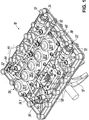
1 eine perspektivische Ansicht einer hydraulischen Betätigungsvorrichtung für die Betätigung von Stellgliedern in einem Kraftfahrzeuggetriebe nach einem bevorzugten Ausführungsbeispiel der Erfindung im nicht-montierten Zustand von schräg oben / vorne links mit Blick auf die von einer Flanschfläche der Betätigungsvorrichtung abgewandte Seite der Betätigungsvorrichtung, auf der insbesondere Steuereinrichtungen der Betätigungsvorrichtung angeordnet sind; -
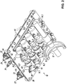
2 eine perspektivische Ansicht der Betätigungsvorrichtung gemäß1 im nicht-montierten Zustand von schräg unten / vorne rechts mit Blick auf Kolben-Zylinder-Anordnungen und die Flanschfläche der Betätigungsvorrichtung, über die die Betätigungsvorrichtung an einer Trennwand eines Getriebegehäuses des Kraftfahrzeuggetriebes angeflanscht werden kann; -
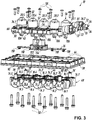
3 eine perspektivische Explosionsdarstellung der Betätigungsvorrichtung gemäß1 von schräg oben / vorne links zur besseren Veranschaulichung einer die Kolben-Zylinder-Anordnungen tragenden ersten Trägerplatte, einer die Steuereinrichtungen tragenden zweiten Trägerplatte und einer dazwischen angeordneten Platine als elektrische Verbindungseinheit zur elektrischen Kontaktierung und Ansteuerung der Steuereinrichtungen; -
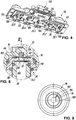
4 eine perspektivische Ansicht der zweiten Trägerplatte der Betätigungsvorrichtung gemäß1 von schräg unten / hinten links mit Blick auf die auf der Unterseite der zweiten Trägerplatte angebrachte Platine; -
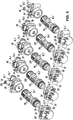
5 eine perspektivische Explosionsdarstellung der Kolben-Zylinder-Anordnungen der Betätigungsvorrichtung gemäß1 von schräg oben / hinten links zur besseren Veranschaulichung von Stellkolben und Zylindergehäusetypen der Kolben-Zylinder-Anordnungen; -
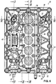
6 eine Draufsicht auf die Betätigungsvorrichtung gemäß1 von oben in1 ; -
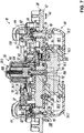
7 eine im Maßstab gegenüber der6 vergrößerte Schnittansicht der Betätigungsvorrichtung gemäß1 entsprechend der SchnittverlaufslinieVII-VII in6 , wobei die Schnittansicht um 180° in der Zeichnungsebene gedreht wurde, um die Einbaulage der Betätigungsvorrichtung zu veranschaulichen; -
8 eine im Maßstab gegenüber der7 nochmals deutlich vergrößerte Schnittansicht der Betätigungsvorrichtung gemäß1 entsprechend dem DetailkreisVIII in7 zur besseren Illustration eines Entlüftungsventils der Betätigungsvorrichtung; -
9 eine Draufsicht auf einen Ventilsitz des Entlüftungsventils der Betätigungsvorrichtung gemäß1 mit Blickrichtung entsprechend dem Pfeil IX in8 ; -
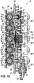
10 eine hinsichtlich des Maßstabs der6 entsprechende Schnittansicht der Betätigungsvorrichtung gemäß1 entsprechend der SchnittverlaufslinieX-X in6 ; -
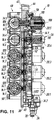
11 eine wiederum hinsichtlich des Maßstabs der6 entsprechende Schnittansicht der Betätigungsvorrichtung gemäß1 entsprechend der zweifach versetzten SchnittverlaufslinieXI-XI in6 ; -
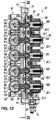
12 eine erneut hinsichtlich des Maßstabs der6 entsprechende Schnittansicht der Betätigungsvorrichtung gemäß1 entsprechend der SchnittverlaufslinieXII-XII in6 ; und -
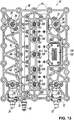
13 eineim Maßstab der 12 entsprechende Schnittansicht der Betätigungsvorrichtung gemäß1 entsprechend der SchnittverlaufslinieXIII-XIII in12 .
-
1 a perspective view of a hydraulic actuating device for the actuation of actuators in a motor vehicle transmission according to a preferred embodiment of the invention in the non-assembled state from obliquely above / front left with a view of the side of the actuating device facing away from a flange surface of the actuating device, in particular on the control devices of the Actuator are arranged; -
2nd a perspective view of the actuator according to1 in the unassembled state from obliquely below / at the front right with a view of piston-cylinder arrangements and the flange surface of the actuating device, via which the actuating device can be flanged to a partition wall of a transmission housing of the motor vehicle transmission; -
3rd a perspective exploded view of the actuator according to1 from obliquely top / front left for better illustration of a first carrier plate carrying the piston-cylinder arrangements, a second carrier plate carrying the control devices and a circuit board arranged between them as an electrical connection unit for electrical contacting and control of the control devices; -
4th a perspective view of the second support plate of the actuator according to1 from obliquely below / behind left with a view of the circuit board attached to the underside of the second carrier plate; -
5 a perspective exploded view of the piston-cylinder arrangements of the actuator according to1 diagonally from top / rear left to better illustrate actuating pistons and cylinder housing types of piston-cylinder arrangements; -
6 a plan view of the actuator according to1 from above in1 ; -
7 one in scale against the6 enlarged sectional view of the actuator according to1 according to the cutting lineVII-VII in6 , wherein the sectional view has been rotated 180 ° in the plane of the drawing to illustrate the installation position of the actuating device; -
8th one in scale against the7 again clearly enlarged sectional view of the actuating device according to1 according to the detail circleVIII in7 for better illustration of a vent valve of the actuating device; -
9 a plan view of a valve seat of the vent valve of the actuator according to1 looking in the direction of arrow IX in8th ; -
10 one in terms of scale6 corresponding sectional view of the actuator according to1 according to the cutting lineXX in6 ; -
11 one again in terms of scale6 corresponding sectional view of the actuator according to1 corresponding to the twice offset cutting lineXI-XI in6 ; -
12th one again in terms of scale6 corresponding sectional view of the actuator according to1 according to the cutting lineXII-XII in6 ; and -
13 one on a scale of12th corresponding sectional view of the actuator according to1 according to the cutting lineXIII-XIII in12th .
DETAILLIERTE BESCHREIBUNG DES AUSFÜHRUNGSBEISPIELSDETAILED DESCRIPTION OF THE EMBODIMENT
In den Figuren beziffert das Bezugszeichen
Im dargestellten Ausführungsbeispiel sind für ein automatisiertes LKW-Schaltgetriebe (ASG) mit acht Vorwärtsgängen und zwei Rückwärtsgängen insgesamt fünf Kolben-Zylinder-Anordnungen
Jeder Kolben-Zylinder-Anordnung
Wie im Folgenden noch im Einzelnen erläutert wird, bestehen im Vergleich zum eingangs geschilderten Stand der Technik verschiedene Besonderheiten der Betätigungsvorrichtung
Zum anderen (ii) ist eine elektrische Verbindungseinheit - hier in der Form einer Platine 36 - zur elektrischen Kontaktierung und Ansteuerung der Steuereinrichtungen
Wie die
Die
Die einzelnen Steuereinrichtungen
Gemäß den
Komplettiert wird der hydraulische Teil der Betätigungsvorrichtung
In den
Gemäß den
Weitere Details der Zylinderbaugruppe
Bei der Reihenanordnung von Zylindergehäusen
Zur Positionierung der Zylindergehäuse
Wie die
Details zu den Entlüftungsventilen
In
Für den Fachmann ist insoweit ersichtlich, dass die Verbindungsnut
Zur Unterstützung der so bewirkten Entlüftung des hydraulischen Systems können im Übrigen die Stellkolben
Weitere Details zu den identisch ausgebildeten Steuereinrichtungen
Demgemäß handelt es sich bei den Steuereinrichtungen
In an sich bekannter Weise kann das Sperrelement
Des Weiteren ist jeder Kolben-Zylinder-Anordnung
Wie die
Insbesondere in den
Gemäß den
Wie in den
Was im Übrigen die Funktionsweise der vorbeschriebenen Betätigungsvorrichtung
Eine hydraulische Betätigungsvorrichtung für die Betätigung von Stellgliedern in einem Kraftfahrzeuggetriebe hat eine Mehrzahl von Kolben-Zylinder-Anordnungen, die jeweils einen mit einem Stellglied wirkverbindbaren Stellkolben aufweisen, der auf einer ersten Seite und einer zweiten Seite über jeweils einen zugeordneten Druckraum hydraulisch beaufschlagt werden kann. Jeder Kolben-Zylinder-Anordnung ist eine Steuereinrichtung zugeordnet, die eine Stellbewegung des jeweiligen Stellkolbens in einer ersten Richtung oder einer entgegengesetzten zweiten Richtung gestattet oder unterbindet. Ferner sind die Druckräume auf der ersten Seite der Stellkolben über eine gemeinsame erste Druckleitung hydraulisch miteinander verbunden, während die Druckräume auf der zweiten Seite der Stellkolben über eine gemeinsame zweite Druckleitung hydraulisch miteinander verbunden sind. Für eine einfache Entlüftung des Systems ist jeder Druckleitung wenigstens ein Entlüftungsventil mit einem Abgang für Luft zugeordnet, wobei die Abgänge der Entlüftungsventile an eine gemeinsame Entlüftungsleitung angeschlossen sind.A hydraulic actuating device for actuating actuators in a motor vehicle transmission has a plurality of piston-cylinder arrangements, each of which has an actuating piston which can be operatively connected to an actuator and which can be acted upon hydraulically on a first side and a second side via an associated pressure chamber. Each piston cylinder The arrangement is assigned a control device which permits or prevents an actuating movement of the respective actuating piston in a first direction or an opposite second direction. Furthermore, the pressure spaces on the first side of the actuating pistons are hydraulically connected to one another via a common first pressure line, while the pressure spaces on the second side of the actuating pistons are hydraulically connected to one another via a common second pressure line. For simple ventilation of the system, each pressure line is assigned at least one ventilation valve with an outlet for air, the outlets of the ventilation valves being connected to a common ventilation line.
BezugszeichenlisteReference list
- 1010th
- BetätigungsvorrichtungActuator
- 1212th
- StellgliedActuator
- 14.114.1
- Kolben-Zylinder-AnordnungPiston-cylinder arrangement
- 14.214.2
- Kolben-Zylinder-AnordnungPiston-cylinder arrangement
- 14.314.3
- Kolben-Zylinder-AnordnungPiston-cylinder arrangement
- 14.414.4
- Kolben-Zylinder-AnordnungPiston-cylinder arrangement
- 14.514.5
- Kolben-Zylinder-AnordnungPiston-cylinder arrangement
- 16.116.1
- StellkolbenAdjusting piston
- 16.216.2
- StellkolbenAdjusting piston
- 16.316.3
- StellkolbenAdjusting piston
- 16.416.4
- StellkolbenAdjusting piston
- 16.516.5
- StellkolbenAdjusting piston
- 18.1, 18.1'18.1, 18.1 '
- DruckraumPressure room
- 18.2, 18.2'18.2, 18.2 '
- DruckraumPressure room
- 18.3, 18.3'18.3, 18.3 '
- DruckraumPressure room
- 18.4, 18.4'18.4, 18.4 '
- DruckraumPressure room
- 18.5, 18.5'18.5, 18.5 '
- DruckraumPressure room
- 20.120.1
- SteuereinrichtungControl device
- 20.220.2
- SteuereinrichtungControl device
- 20.320.3
- SteuereinrichtungControl device
- 20.420.4
- SteuereinrichtungControl device
- 20.520.5
- SteuereinrichtungControl device
- 2222
- erste Druckleitungfirst pressure line
- 2424th
- zweite Druckleitungsecond pressure line
- 2626
- EntlüftungsventilVent valve
- 2828
- EntlüftungsventilVent valve
- 3030th
- AbgangFinish
- 3232
- AbgangFinish
- 3434
- EntlüftungsleitungVent line
- 34.134.1
- LeitungsabschnittLine section
- 34.234.2
- LeitungsabschnittLine section
- 3636
- Platinecircuit board
- 3838
- erste Trägerplattefirst carrier plate
- 4040
- zweite Trägerplattesecond carrier plate
- 4242
- FlanschflächeFlange surface
- 4444
- BefestigungslochMounting hole
- 4646
- ZentrierhülseCentering sleeve
- 4848
- ZylinderbaugruppeCylinder assembly
- 5050
- BefestigungsschraubeMounting screw
- 5252
- HalteplatteRetaining plate
- 5454
- BefestigungsschraubeMounting screw
- 5656
- SteuerbaugruppeControl module
- 5858
- BefestigungsschraubeMounting screw
- 6060
- ZentrierfortsatzCentering process
- 6262
- ZentrieraussparungCentering recess
- 6464
- AnschlussgehäuseJunction box
- 6666
- VentilgehäuseValve body
- 6868
- Halterholder
- 7070
- SteckanschlussPlug-in connection
- 7272
- SteckanschlussPlug-in connection
- 74.1, 74.1'74.1, 74.1 '
- ZylindergehäuseCylinder housing
- 74.2, 74.2'74.2, 74.2 '
- ZylindergehäuseCylinder housing
- 74.3, 74.3'74.3, 74.3 '
- ZylindergehäuseCylinder housing
- 74.4, 74.4'74.4, 74.4 '
- ZylindergehäuseCylinder housing
- 74.5, 74.5'74.5, 74.5 '
- ZylindergehäuseCylinder housing
- 76, 76'76, 76 '
- HydraulikeingangHydraulic input
- 78, 78'78, 78 '
- HydraulikausgangHydraulic outlet
- 80, 80'80, 80 '
- EingangsanschlussInput connector
- 82, 82'82, 82 '
- EndanschlussEnd connection
- 8484
- PositioniervorsprungPositioning projection
- 8686
- PositionieraussparungPositioning recess
- 8888
- Öffnungopening
- 9090
- AnschlagleisteStop bar
- 9292
- VentilkörperValve body
- 9494
- VentilsitzValve seat
- 9696
- EinsatzteilInsert part
- 9898
- O-RingO-ring
- 100100
- DurchgangContinuity
- 102 102
- RingnutRing groove
- 104104
- VerbindungsnutConnecting groove
- 106106
- SperrelementLocking element
- 108108
- Federfeather
- 110110
- AktuatorActuator
- 112112
- ZustellachseInfeed axis
- 113113
- Öffnungopening
- 114114
- AussparungRecess
- 116116
- SensoranordnungSensor arrangement
- 118118
- PositionsdetektorPosition detector
- 120120
- PositionsgeberPosition transmitter
- 122122
- AussparungRecess
- 124124
- BefestigungsschraubeMounting screw
- 126126
- DichtungsanordnungSealing arrangement
- 128128
- KontaktstiftContact pin
- 130130
- elektrische Schnittstelleelectrical interface
- 132132
- SteckanschlussPlug-in connection
- 134134
- KontaktstiftContact pin
ZITATE ENTHALTEN IN DER BESCHREIBUNG QUOTES INCLUDE IN THE DESCRIPTION
Diese Liste der vom Anmelder aufgeführten Dokumente wurde automatisiert erzeugt und ist ausschließlich zur besseren Information des Lesers aufgenommen. Die Liste ist nicht Bestandteil der deutschen Patent- bzw. Gebrauchsmusteranmeldung. Das DPMA übernimmt keinerlei Haftung für etwaige Fehler oder Auslassungen.This list of documents listed by the applicant has been generated automatically and is only included for the better information of the reader. The list is not part of the German patent or utility model application. The DPMA assumes no liability for any errors or omissions.
Zitierte PatentliteraturPatent literature cited
- EP 2754911 A1 [0003, 0007, 0058]EP 2754911 A1 [0003, 0007, 0058]
- DE 102018008943 [0049]DE 102018008943 [0049]
- EP 2543891 A2 [0050]EP 2543891 A2 [0050]
Claims (15)
Priority Applications (4)
| Application Number | Priority Date | Filing Date | Title |
|---|---|---|---|
| DE102018009852.5A DE102018009852A1 (en) | 2018-12-19 | 2018-12-19 | Hydraulic actuating device for actuating actuators in a motor vehicle transmission |
| EP19216139.6A EP3670972B1 (en) | 2018-12-19 | 2019-12-13 | Hydraulic operating apparatus for the operation of actuating elements in a motor vehicle transmission |
| CN201911301060.6A CN111336249B (en) | 2018-12-19 | 2019-12-17 | Hydraulic operating device for operating actuating elements in motor vehicle transmissions |
| KR1020190169792A KR102838290B1 (en) | 2018-12-19 | 2019-12-18 | Hydraulic operating apparatus for the operation of actuating elements in a motor vehicle transmission |
Applications Claiming Priority (1)
| Application Number | Priority Date | Filing Date | Title |
|---|---|---|---|
| DE102018009852.5A DE102018009852A1 (en) | 2018-12-19 | 2018-12-19 | Hydraulic actuating device for actuating actuators in a motor vehicle transmission |
Publications (1)
| Publication Number | Publication Date |
|---|---|
| DE102018009852A1 true DE102018009852A1 (en) | 2020-06-25 |
Family
ID=68917335
Family Applications (1)
| Application Number | Title | Priority Date | Filing Date |
|---|---|---|---|
| DE102018009852.5A Withdrawn DE102018009852A1 (en) | 2018-12-19 | 2018-12-19 | Hydraulic actuating device for actuating actuators in a motor vehicle transmission |
Country Status (4)
| Country | Link |
|---|---|
| EP (1) | EP3670972B1 (en) |
| KR (1) | KR102838290B1 (en) |
| CN (1) | CN111336249B (en) |
| DE (1) | DE102018009852A1 (en) |
Cited By (1)
| Publication number | Priority date | Publication date | Assignee | Title |
|---|---|---|---|---|
| DE102022203574A1 (en) | 2022-04-08 | 2023-10-12 | Zf Friedrichshafen Ag | Hydraulic fluid supply arrangement for a vehicle |
Families Citing this family (1)
| Publication number | Priority date | Publication date | Assignee | Title |
|---|---|---|---|---|
| DE102020126169A1 (en) * | 2020-10-07 | 2022-04-07 | Zf Cv Systems Global Gmbh | Sensor arrangement of an automated manual transmission and method for determining a magnetic interference field |
Citations (5)
| Publication number | Priority date | Publication date | Assignee | Title |
|---|---|---|---|---|
| DE3725578A1 (en) * | 1986-08-08 | 1988-02-18 | Zahnradfabrik Friedrichshafen | ELECTRO-HYDRAULIC CONTROL FOR AN AUTOMATIC GEARBOX TRANSMISSION |
| EP2543891A2 (en) | 2011-07-06 | 2013-01-09 | FTE automotive GmbH & Co. KG | Hydraulic actuation device for actuating one or more positioning members, particularly in motor vehicles |
| EP2754911A1 (en) | 2013-01-09 | 2014-07-16 | FTE automotive GmbH | Hydraulic actuation device for actuating at least a friction clutch transmission and at least one gear actuator in a motor vehicle |
| DE102018104854A1 (en) * | 2017-03-16 | 2018-09-20 | GM Global Technology Operations LLC | Hydraulic control system for an automatic transmission |
| DE102018008943A1 (en) | 2018-11-14 | 2020-05-14 | Fte Automotive Gmbh | Method for venting a device for the hydraulic actuation of at least one friction clutch and / or at least one transmission actuator |
Family Cites Families (5)
| Publication number | Priority date | Publication date | Assignee | Title |
|---|---|---|---|---|
| FR2806671B1 (en) * | 2000-03-24 | 2002-05-31 | Renault | DEVICE FOR HYDRAULICALLY CONTROLLING GEAR CHANGES OF A MOTOR VEHICLE GEARBOX |
| DE10308216B4 (en) * | 2003-02-25 | 2014-01-23 | Volkswagen Ag | automatic transmission |
| DE102013008956A1 (en) * | 2013-05-27 | 2014-11-27 | Knorr-Bremse Systeme für Nutzfahrzeuge GmbH | Actuating device for a motor vehicle transmission or a motor vehicle clutch |
| CN106662171B (en) * | 2014-08-11 | 2020-02-28 | 舍弗勒技术股份两合公司 | Double clutch operating device |
| CN109642593B (en) * | 2016-08-05 | 2023-04-18 | 康斯博格汽车股份公司 | Position actuator with pneumatic venting |
-
2018
- 2018-12-19 DE DE102018009852.5A patent/DE102018009852A1/en not_active Withdrawn
-
2019
- 2019-12-13 EP EP19216139.6A patent/EP3670972B1/en active Active
- 2019-12-17 CN CN201911301060.6A patent/CN111336249B/en active Active
- 2019-12-18 KR KR1020190169792A patent/KR102838290B1/en active Active
Patent Citations (5)
| Publication number | Priority date | Publication date | Assignee | Title |
|---|---|---|---|---|
| DE3725578A1 (en) * | 1986-08-08 | 1988-02-18 | Zahnradfabrik Friedrichshafen | ELECTRO-HYDRAULIC CONTROL FOR AN AUTOMATIC GEARBOX TRANSMISSION |
| EP2543891A2 (en) | 2011-07-06 | 2013-01-09 | FTE automotive GmbH & Co. KG | Hydraulic actuation device for actuating one or more positioning members, particularly in motor vehicles |
| EP2754911A1 (en) | 2013-01-09 | 2014-07-16 | FTE automotive GmbH | Hydraulic actuation device for actuating at least a friction clutch transmission and at least one gear actuator in a motor vehicle |
| DE102018104854A1 (en) * | 2017-03-16 | 2018-09-20 | GM Global Technology Operations LLC | Hydraulic control system for an automatic transmission |
| DE102018008943A1 (en) | 2018-11-14 | 2020-05-14 | Fte Automotive Gmbh | Method for venting a device for the hydraulic actuation of at least one friction clutch and / or at least one transmission actuator |
Cited By (1)
| Publication number | Priority date | Publication date | Assignee | Title |
|---|---|---|---|---|
| DE102022203574A1 (en) | 2022-04-08 | 2023-10-12 | Zf Friedrichshafen Ag | Hydraulic fluid supply arrangement for a vehicle |
Also Published As
| Publication number | Publication date |
|---|---|
| EP3670972B1 (en) | 2021-07-07 |
| KR20200076638A (en) | 2020-06-29 |
| CN111336249A (en) | 2020-06-26 |
| CN111336249B (en) | 2022-10-21 |
| EP3670972A1 (en) | 2020-06-24 |
| KR102838290B1 (en) | 2025-07-25 |
Similar Documents
| Publication | Publication Date | Title |
|---|---|---|
| EP3082406B1 (en) | Safety valve | |
| DE19537482A1 (en) | Hydraulic control block | |
| DE102011116472A1 (en) | Hydraulic or pneumatic actuator for actuating a valve with a control or switching valve | |
| EP3390177B1 (en) | Valve unit for modulating the pressure in a pneumatic brake system | |
| DE102007047124A1 (en) | Hydraulic unit for a slip-controlled hydraulic vehicle brake system | |
| WO2010057560A1 (en) | Valve and assembly method | |
| DE102017206394A1 (en) | Pressure holding valve arrangement for a rinsing circuit of a closed hydraulic circuit | |
| WO2017125108A1 (en) | Hydraulic switching assembly for a motor vehicle | |
| DE69517386T2 (en) | Valve with four connection openings and two positions | |
| DE102018214006A1 (en) | Hydraulic system and automotive transmission | |
| DE102018009852A1 (en) | Hydraulic actuating device for actuating actuators in a motor vehicle transmission | |
| DE102014224201A1 (en) | Hydrostatic clutch actuator | |
| DE202006016377U1 (en) | Lubricating block for heavy industrial machinery has internal lubricant dosing unit and router linked to an array of outlet injectors | |
| EP2647883B1 (en) | Hydraulic control device | |
| DE3015830A1 (en) | LOCKING DEVICE FOR PISTON-CYLINDER UNITS | |
| DE112020000079T5 (en) | ELECTROMAGNETIC CONTROL VALVE | |
| DE102012001100A1 (en) | Arrangement for controlling a double-acting switching cylinder of a Schaltanord-tion of an automated transmission of a motor vehicle | |
| DE102010025078A1 (en) | Device for ventilating hydraulic passage leading from pressure source to actuator of dual clutch transmission of motor car, has vent valve comprising spring for applying force to valve member such that fluid is pushed against valve seat | |
| DE102018009853B4 (en) | Hydraulic actuator for operating actuators in a motor vehicle transmission | |
| DE102011116632A1 (en) | Valve, hydraulic arrangement with such a valve and use of a button or switch for a valve | |
| EP3169902B1 (en) | Screw compressor | |
| DE102018208755A1 (en) | Pressure control valve | |
| DE19727158C2 (en) | Control device | |
| DE102016216264A1 (en) | Fluid arrangement for actuating vehicle components | |
| DE10258266A1 (en) | Actuating unit for electrohydraulic brake-by-wire motor vehicle brake system with at least one brake circuit, has simulator spring and chamber in parallel between pressure piston and actuating element |
Legal Events
| Date | Code | Title | Description |
|---|---|---|---|
| R163 | Identified publications notified | ||
| R119 | Application deemed withdrawn, or ip right lapsed, due to non-payment of renewal fee |