EP2754552B1 - Séparateur à vis sans fin de presse et procédé de fonctionnement du séparateur à vis sans fin de presse - Google Patents
Séparateur à vis sans fin de presse et procédé de fonctionnement du séparateur à vis sans fin de presse Download PDFInfo
- Publication number
- EP2754552B1 EP2754552B1 EP13000088.8A EP13000088A EP2754552B1 EP 2754552 B1 EP2754552 B1 EP 2754552B1 EP 13000088 A EP13000088 A EP 13000088A EP 2754552 B1 EP2754552 B1 EP 2754552B1
- Authority
- EP
- European Patent Office
- Prior art keywords
- screen
- screw
- retaining element
- longitudinal direction
- press separator
- Prior art date
- Legal status (The legal status is an assumption and is not a legal conclusion. Google has not performed a legal analysis and makes no representation as to the accuracy of the status listed.)
- Active
Links
- 238000000034 method Methods 0.000 title claims description 7
- 239000007787 solid Substances 0.000 claims description 21
- 239000007788 liquid Substances 0.000 claims description 8
- 238000005406 washing Methods 0.000 claims description 8
- 238000004140 cleaning Methods 0.000 claims description 7
- 239000002002 slurry Substances 0.000 description 8
- 230000033001 locomotion Effects 0.000 description 4
- 230000010006 flight Effects 0.000 description 2
- 239000008394 flocculating agent Substances 0.000 description 2
- 238000012423 maintenance Methods 0.000 description 2
- 239000002351 wastewater Substances 0.000 description 2
- XLYOFNOQVPJJNP-UHFFFAOYSA-N water Substances O XLYOFNOQVPJJNP-UHFFFAOYSA-N 0.000 description 2
- 241000237858 Gastropoda Species 0.000 description 1
- 230000003213 activating effect Effects 0.000 description 1
- 239000000470 constituent Substances 0.000 description 1
- 230000001419 dependent effect Effects 0.000 description 1
- 210000003608 fece Anatomy 0.000 description 1
- 238000009434 installation Methods 0.000 description 1
- 239000010871 livestock manure Substances 0.000 description 1
- 238000004519 manufacturing process Methods 0.000 description 1
- 238000003825 pressing Methods 0.000 description 1
- 230000001105 regulatory effect Effects 0.000 description 1
- 239000010801 sewage sludge Substances 0.000 description 1
- 239000010802 sludge Substances 0.000 description 1
Images


Classifications
-
- B—PERFORMING OPERATIONS; TRANSPORTING
- B30—PRESSES
- B30B—PRESSES IN GENERAL
- B30B9/00—Presses specially adapted for particular purposes
- B30B9/02—Presses specially adapted for particular purposes for squeezing-out liquid from liquid-containing material, e.g. juice from fruits, oil from oil-containing material
- B30B9/12—Presses specially adapted for particular purposes for squeezing-out liquid from liquid-containing material, e.g. juice from fruits, oil from oil-containing material using pressing worms or screws co-operating with a permeable casing
- B30B9/121—Screw constructions
-
- B—PERFORMING OPERATIONS; TRANSPORTING
- B30—PRESSES
- B30B—PRESSES IN GENERAL
- B30B9/00—Presses specially adapted for particular purposes
- B30B9/02—Presses specially adapted for particular purposes for squeezing-out liquid from liquid-containing material, e.g. juice from fruits, oil from oil-containing material
- B30B9/12—Presses specially adapted for particular purposes for squeezing-out liquid from liquid-containing material, e.g. juice from fruits, oil from oil-containing material using pressing worms or screws co-operating with a permeable casing
-
- B—PERFORMING OPERATIONS; TRANSPORTING
- B30—PRESSES
- B30B—PRESSES IN GENERAL
- B30B9/00—Presses specially adapted for particular purposes
- B30B9/02—Presses specially adapted for particular purposes for squeezing-out liquid from liquid-containing material, e.g. juice from fruits, oil from oil-containing material
- B30B9/26—Permeable casings or strainers
Definitions
- the present invention relates to a press screw separator for separating solid components from a slurry containing solid and liquid components according to claim 1, and a method for operating the press screw separator according to claim 11.
- Press screw separators comprise a cylindrical screen, such as US 2011/0186499 A1 is known.
- a rotating screw is arranged in the sieve.
- the pulp is squeezed out within the sieve, so that the liquid components pass through the lateral surface of the sieve.
- a Feststoffpfropfen forms.
- Wastewater from municipal, industrial or agricultural enterprises eg liquid manure or flocculants treated municipal sewage sludge
- cleaning of the screen is required at regular intervals.
- a press screw separator according to the preamble of claim 1, for example, from JP 2004-066306 A known. It is an object of the present invention to provide a press screw separator, which can be operated at low cost production and installation low maintenance. In particular, the cylindrical sieve should be rotatable together with the screw for cleaning purposes. Furthermore, it is an object of the present invention to specify a corresponding method for operating the press screw separator. The object is achieved by the features of the independent claims. The dependent claims relate to advantageous embodiments of the invention. Thus, the object is achieved by a press screw separator for separating solid components from a slurry containing solid and liquid components. Wastewater from municipal, industrial or agricultural enterprises is used as the slurry, which may be stabilized with flocculants.
- the press screw separator comprises a housing and a cylindrical screen disposed in the housing. Furthermore, a worm is rotatably mounted in the housing. The worm extends at least partially into the cylindrical sieve. According to the cylindrical shape of the screen, a longitudinal direction and a circumferential direction are defined. The worm is rotatably mounted about the longitudinal axis. For cleaning the screen is provided that the screen is arranged rotatably about the longitudinal direction.
- the sieve does not require its own drive, since with a sufficient solids content between the screw and the sieve a torque is transmitted from the screw to the sieve.
- at least one retaining element is arranged in the housing, in particular between a housing wall and the lateral surface of the screen. Furthermore, an actuator is provided.
- the holding element By means of the actuator, the holding element can be moved into a locking position and in a freewheeling position.
- One end of the actuator is in particular firmly connected to the housing.
- the other end of the actuator is connected to the retaining element.
- On the screen, in particular on the lateral surface of the screen, at least one fixed stop is provided on the screen, in particular on the lateral surface of the screen.
- This "locking position” is also referred to as "working position”.
- the at least one holding element is moved by means of the actuator in the freewheeling position.
- the retaining element moves away from the stop. In the free-running position, the screen rotates with the worm. This makes it possible to clean the sieve from all sides. According to the invention, therefore, the retaining element is actively moved, with the actuator, in the locking position and freewheeling position.
- the holding element and the corresponding stop on the screen can act over the entire length of the screen, so that the force between the holding element and the stop is transmitted over as large a surface as possible.
- the worm it is possible in accordance with the invention for the worm to rotate in the same direction both when the pulp is pressed out and when the sieve is cleaned.
- the holding element is designed as a longitudinally extending holding rail.
- the retaining rail extends in the longitudinal direction over a holding element length.
- the sieve extends longitudinally over a sieve length. It is preferably provided that the holding element length is at least 50%, preferably at least 75%, particularly preferably 100%, of the sieve length. Furthermore, it is preferably provided that the stop or the plurality of stops extend over at least 50%, preferably over at least 75%, particularly preferably over at least 95%, of the holding element length.
- the force between stop and retaining element is transmitted over as large as possible. Due to the fact that the sieve is supported against rotation on the retaining rail not only at its front ends but along its entire length, the sieve does not have to be very rigid. This has significant advantages during the squeezing of the pulp.
- the sieve deforms elliptically, depending on the position of the usually double-barreled screw and / or the amount of the solid.
- the inventive design of the press screw separator the screen may be relatively unstable, so that this deformation is possible during the squeezing of the pulp. Furthermore, the gap between the screw flights and the inner diameter of the screen can thereby be kept as small as possible, since contact between the screw flights and the screen is effectively avoided.
- the retaining rail is preferably arranged parallel to the longitudinal direction.
- the retaining rail is moved away from the lateral surface of the screen to the outside. In particular, this movement takes place in a radial direction perpendicular to the longitudinal direction.
- the retaining rail is arranged parallel to the longitudinal direction both in the locking position and in the freewheeling position.
- the retaining rail is preferably mounted on at least one guide element in the housing.
- This guide element preferably has a housing-fixed cylinder, in which a piston is guided. The piston is connected to the retaining rail.
- washing nozzles distributed along the longitudinal direction are preferably arranged.
- water can be sprayed from outside onto the sieve in order to clean the sieve. Since the screen rotates during cleaning, it is sufficient to arrange only one row of washing nozzles.
- a sensor for detecting a rotational angle and / or a rotational speed of the sieve is preferably provided.
- the movement of the at least one retaining element from the freewheeling position into the locking position preferably takes place as a function of the data detected by the sensor. This will ensure that the Retaining element moves in the locking position at the right time, so that the stop rests against the holding element.
- a plurality of holding elements are provided along the circumferential direction of the screen.
- at least one actuator and in each case at least one fixedly connected to the screen stop is provided.
- the actuator is preferably hydraulically, pneumatically or electrically operated.
- the worm preferably comprises a conical worm core and at least one worm helix arranged on the worm core. Furthermore, an inlet for the pulp is arranged on the press screw separator on one end face of the cylindrical screen. At the other end of the screen a solids outlet is formed.
- the conical worm core preferably tapers towards the inlet.
- a cone ring is preferably arranged, which regulates the discharge amount of the solid.
- the invention further comprises a method for operating the proposed press screw separator. The following steps are provided: (i) squeezing the slurry, wherein the screw is rotated and the holding element is in the locking position, (ii) moving the holding element into the free-running position, (iii) rotating the screw while the holding element is in the free-running position, so that the wire rotates with the screw, and (iv) cleaning the wire while the wire is rotating with the screw.
- a short-term switching off of the drive of the worm is preferably carried out.
- the worm is set in rotation again.
- the screw rotates to squeeze the pulp and during cleaning of the sieve in the same direction.
- the mentioned washing nozzles are turned on.
- the rotation of the screen is monitored by the sensor.
- the sensor passes a certain turning path of the screen to the actuator. Accordingly, the actuator moves the retaining element back into the Lock position. The sieve is caught by the holding elements and prevented from further rotation. Then again the squeezing of the pulp can take place.
- the holding elements can also be adjusted for maintenance, for example, to prevent falling of the screen when disassembling the screw.
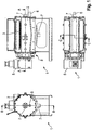
- Fig. 1 shows three different views of the press screw separator 1.
- the Fig. 2 to 3 show the in Fig. 1 marked sections.
- Fig. 5 shows that in Fig. 4 marked detail V.
- the press screw separator 1 comprises a housing 2.
- a cylindrical sieve 3 is arranged.
- a worm 4 is rotatably mounted in the housing 2.
- the worm 4 extends through the cylindrical sieve 3.
- a drive 5 designed as an electric motor or hydraulic motor, is provided.
- an inlet 6 is formed in the housing.
- the pulp to be squeezed out is directed into the interior of the sieve 3.
- a solids outlet 8 is provided at the left end of the screen 3.
- a drain 7 is provided at the bottom of the housing 2, for the liquid components of the slurry. Another sequence 7 is possible at a front end of the hollow screw 4.
- the supplied via the inlet 6 pulp is squeezed by the rotation of the screw 4 from right to left. This forms a solid plug in the left area.
- the solid leaves the press screw separator 1 via the solids outlet 8.
- the separated liquid constituents flow out through the sieve 3 and leave the press screw separator 1 via the outlet 7.
- Fig. 2 shows a conical ring 9 at the solids outlet 8.
- the position of the cone ring 9, the amount of the discharged solid is regulated.
- the screw 4 comprises a screw core 10 and at least one arranged on the screw core 10 screw flight 11.
- the screw core 10 is conical and tapers in the direction of the inlet. 6
- Fig. 2-4 show a longitudinal direction 13.
- this longitudinal direction 13 extend the sieve 3 and the screw 4.
- the screw 4 is rotated about the longitudinal direction 13.
- Perpendicular to the longitudinal direction 13 is a radial direction 14.
- the circumferential direction 15 is defined around the longitudinal direction 13.
- a plurality of washing nozzles 12 are arranged along the longitudinal direction 13.
- a liquid in particular water, can be injected from the outside onto the sieve 3.
- Fig. 3 shows two retaining elements 17, designed as retaining rails.
- the holding elements 17 each extend in the longitudinal direction 13.
- the holding elements 17 are connected via an actuator 16 and guide elements 18 fixed to the housing 2.
- the actuator 16 By means of the actuator 16, the holding elements 13 can be moved inwards, in the direction of the wire 3, and outwardly, away from the wire 3.
- Fig. 3 shows further that 3 stops 19 are formed on the screen.
- the exact design of the holding member 17 and the stopper 19 shows the enlarged view in FIG Fig. 5 ,
- the stop 19 shown is firmly connected to the wire 3.
- the stop 19 abuts against the retaining element 17.
- the position shown in the figures is referred to as the "locking position".
- the actuator 16 By means of the actuator 16, the holding member 17 can be moved to the outside. As a result, the stop 19 is no longer on the holding element 17, whereby a rotation of the wire 3 is possible.
- the guide elements 18 have a housing-fixed cylinder 23. In this cylinder 23, a piston 24 is guided linearly movable. The piston 24 is connected to the holding element 17.
- Fig. 2 shows a Siebrati 20 of the screen 3.
- Fig. 3 shows a holding element length 21 of the holding member 17.
- the holding element length 21 is formed as large as possible, so that over as large a portion of the Siebin 20, the force between the holding member 17 and the stopper 19 can be transmitted.
- Fig. 4 shows a sensor 22. By means of the sensor 22, the rotational movement of the screen 3 is detected.
Landscapes
- Engineering & Computer Science (AREA)
- Mechanical Engineering (AREA)
- Filtration Of Liquid (AREA)
- Treatment Of Sludge (AREA)
Claims (11)
- Séparateur à vis sans fin de presse (1) pour la séparation de particules solides d'une eau trouble contenant des particules solides et liquides, comprenant- un boîtier (2),- un tamis (3) cylindrique disposé dans le boîtier (2) sur lequel un sens longitudinal (13) et un sens périphérique (15) sont définis, dans lequel le tamis (3) est mobile en rotation autour du sens longitudinal (13),- une vis sans fin (4) disposée dans le tamis (3) pour le pressage de l'eau trouble, dans lequel la vis sans fin (4) est mobile en rotation autour du sens longitudinal (13),- au moins un élément de retenue (17) disposé dans le boîtier (2),- au moins un actionneur (16) pour le déplacement de l'au moins un élément de retenue (17) entre une position de verrouillage et une position de marche à vide,- au moins une butée (19) raccordée fixement au tamis (3) qui est réalisée pour le repos contre l'élément de retenue (17) dans la position de verrouillage de sorte que, dans la position de verrouillage, le tamis (3) soit résistant à la rotation dans au moins un sens périphérique (15) et, dans la position de marche à vide, le tamis (3) tourne avec la vis sans fin (4),dans lequel par les particules solides de l'eau trouble un couple peut être transmis de la vis sans fin (4) au tamis (3) afin d'entraîner le tamis (3) dans la position de marche à vide de l'élément de retenue (17), caractérisé en ce que l'élément de retenue (17) est réalisé en tant que rail de retenue s'étendant dans le sens longitudinal (13).
- Séparateur à vis sans fin de presse selon la revendication 1, caractérisé en ce que le rail de retenue s'étend dans le sens longitudinal (13) sur une longueur d'élément de retenue (21) et le tamis (3), dans le sens longitudinal (13) sur une longueur de tamis (20), dans lequel la longueur d'élément de retenue (21) s'élève au moins à 50 %, de préférence au moins à 75 %, de la longueur de tamis (20).
- Séparateur à vis sans fin de presse selon la revendication 1 ou 2, caractérisé en ce que la butée (19) ou les plusieurs butées s'étendent sur au moins 50 %, de préférence sur au moins 75 %, de la longueur d'élément de retenue (21).
- Séparateur à vis sans fin de presse selon l'une quelconque des revendications précédentes, caractérisé en ce que le rail de retenue est disposé dans la position de verrouillage et dans la position de marche à vide parallèlement au sens longitudinal (13).
- Séparateur à vis sans fin de presse selon l'une quelconque des revendications précédentes, caractérisé en ce que plusieurs buses de lavage (12) réparties le long du sens longitudinal (13) sont disposées dans le boîtier (2).
- Séparateur à vis sans fin de presse selon l'une quelconque des revendications précédentes, caractérisé par un capteur (22) pour la détection d'un angle de rotation et/ou d'une vitesse de rotation du tamis (3).
- Séparateur à vis sans fin de presse selon l'une quelconque des revendications précédentes, caractérisé par plusieurs éléments de retenue (17) répartis le long du sens périphérique (15) du tamis (3) avec respectivement au moins un actionneur (16) et respectivement au moins une butée (19) raccordée fixement au tamis (3).
- Séparateur à vis sans fin de presse selon l'une quelconque des revendications précédentes, caractérisé en ce que l'actionneur (16) fonctionne par voie hydraulique ou pneumatique ou électrique.
- Séparateur à vis sans fin de presse selon l'une quelconque des revendications précédentes, caractérisé en ce que la vis sans fin (4) comporte une tige de vis sans fin (10) conique et au moins une hélice de vis sans fin (11) disposée sur la tige de vis sans fin (10).
- Séparateur à vis sans fin de presse selon l'une quelconque des revendications précédentes, caractérisé en ce qu'une alimentation (6) pour l'eau trouble est réalisée sur un côté avant du tamis (3) cylindrique, et une sortie de matières solides (8) est réalisée sur l'autre côté avant.
- Procédé de fonctionnement d'un séparateur à vis sans fin de presse (1) selon l'une quelconque des revendications précédentes, comprenant les étapes suivantes :- pressage d'une eau trouble, dans lequel la vis sans fin (4) tourne et l'élément de retenue (17) est dans la position de verrouillage,- déplacement de l'élément de retenue (17) dans la position de marche à vide,- rotation de la vis sans fin (4), alors que l'élément de retenue (17) est dans la position de marche à vide de sorte que le tamis (3) tourne avec la vis sans fin (4), et- nettoyage du tamis (3) alors que le tamis (3) tourne avec la vis sans fin (4).
Priority Applications (6)
| Application Number | Priority Date | Filing Date | Title |
|---|---|---|---|
| PL13000088T PL2754552T3 (pl) | 2013-01-09 | 2013-01-09 | Separator ślimakowy oraz sposób działania separatora ślimakowego |
| ES13000088.8T ES2681047T3 (es) | 2013-01-09 | 2013-01-09 | Separador por presión helicoidal y procedimiento para la operación del separador por presión helicoidal |
| HUE13000088A HUE038801T2 (hu) | 2013-01-09 | 2013-01-09 | Préscsigás szeparátor és eljárás préscsigás szeparátor üzemeltetésére |
| EP13000088.8A EP2754552B1 (fr) | 2013-01-09 | 2013-01-09 | Séparateur à vis sans fin de presse et procédé de fonctionnement du séparateur à vis sans fin de presse |
| US14/760,088 US10195806B2 (en) | 2013-01-09 | 2014-01-02 | Screw press separator and method for operating the screw press separator |
| PCT/EP2014/050018 WO2014108349A1 (fr) | 2013-01-09 | 2014-01-02 | Séparateur à vis à pression et procédé permettant de faire fonctionner un séparateur à vis à pression |
Applications Claiming Priority (1)
| Application Number | Priority Date | Filing Date | Title |
|---|---|---|---|
| EP13000088.8A EP2754552B1 (fr) | 2013-01-09 | 2013-01-09 | Séparateur à vis sans fin de presse et procédé de fonctionnement du séparateur à vis sans fin de presse |
Publications (2)
| Publication Number | Publication Date |
|---|---|
| EP2754552A1 EP2754552A1 (fr) | 2014-07-16 |
| EP2754552B1 true EP2754552B1 (fr) | 2018-05-02 |
Family
ID=47522375
Family Applications (1)
| Application Number | Title | Priority Date | Filing Date |
|---|---|---|---|
| EP13000088.8A Active EP2754552B1 (fr) | 2013-01-09 | 2013-01-09 | Séparateur à vis sans fin de presse et procédé de fonctionnement du séparateur à vis sans fin de presse |
Country Status (6)
| Country | Link |
|---|---|
| US (1) | US10195806B2 (fr) |
| EP (1) | EP2754552B1 (fr) |
| ES (1) | ES2681047T3 (fr) |
| HU (1) | HUE038801T2 (fr) |
| PL (1) | PL2754552T3 (fr) |
| WO (1) | WO2014108349A1 (fr) |
Families Citing this family (3)
| Publication number | Priority date | Publication date | Assignee | Title |
|---|---|---|---|---|
| DK3026026T3 (da) * | 2013-07-26 | 2019-07-08 | Ishigaki Mech Ind | Genindvindingsapparat og genindvindingsfremgangsmåde til genindvinding af specifikt materiale fra slam |
| US10486383B1 (en) * | 2018-12-18 | 2019-11-26 | V.Y.F. Express Inc. | Screw press having screen vibration |
| US11162218B1 (en) | 2020-09-30 | 2021-11-02 | Robert Clayton | Biomass pulp digester |
Family Cites Families (11)
| Publication number | Priority date | Publication date | Assignee | Title |
|---|---|---|---|---|
| US4844799A (en) * | 1986-07-17 | 1989-07-04 | Lee Chung Y | Filtration apparatus having spaced-apart driving members for changing a size of a treatment zone |
| AU654681B2 (en) * | 1991-09-24 | 1994-11-17 | Ishigaki Company Limited | Screw press |
| JP2868146B2 (ja) * | 1994-06-09 | 1999-03-10 | 株式会社石垣 | スクリュープレスの外筒スクリーンの洗浄装置 |
| CA2360793C (fr) * | 1999-11-30 | 2006-06-13 | Ishigaki Company Limited | Presse a vis |
| JP2003033896A (ja) * | 2001-07-17 | 2003-02-04 | Kubota Corp | スクリュープレスの外胴構造 |
| JP3944723B2 (ja) * | 2002-08-07 | 2007-07-18 | 株式会社石垣 | 濃縮機能を有するスクリュープレス |
| JP4472459B2 (ja) * | 2004-08-11 | 2010-06-02 | 前澤工業株式会社 | スクリュープレスのスクリーン洗浄装置 |
| JP4427798B2 (ja) * | 2005-04-14 | 2010-03-10 | 株式会社石垣 | 差速回転濃縮機における運転制御方法並びに運転制御装置 |
| DE202010001758U1 (de) * | 2010-02-02 | 2011-06-09 | UTS Biogastechnik GmbH, 85399 | Schneckenseparator |
| KR101106168B1 (ko) * | 2011-09-30 | 2012-01-18 | 주식회사 이앤에프 | 스크류탈수기 |
| US9561978B2 (en) * | 2012-04-20 | 2017-02-07 | Anaergia Inc. | Sludge screw thickener with screen rotation during cleaning |
-
2013
- 2013-01-09 HU HUE13000088A patent/HUE038801T2/hu unknown
- 2013-01-09 PL PL13000088T patent/PL2754552T3/pl unknown
- 2013-01-09 ES ES13000088.8T patent/ES2681047T3/es active Active
- 2013-01-09 EP EP13000088.8A patent/EP2754552B1/fr active Active
-
2014
- 2014-01-02 WO PCT/EP2014/050018 patent/WO2014108349A1/fr active Application Filing
- 2014-01-02 US US14/760,088 patent/US10195806B2/en active Active
Non-Patent Citations (1)
| Title |
|---|
| None * |
Also Published As
| Publication number | Publication date |
|---|---|
| US10195806B2 (en) | 2019-02-05 |
| WO2014108349A1 (fr) | 2014-07-17 |
| PL2754552T3 (pl) | 2018-12-31 |
| HUE038801T2 (hu) | 2018-11-28 |
| US20160001516A1 (en) | 2016-01-07 |
| EP2754552A1 (fr) | 2014-07-16 |
| ES2681047T3 (es) | 2018-09-11 |
Similar Documents
| Publication | Publication Date | Title |
|---|---|---|
| WO2010108932A1 (fr) | Dispositif de coupe | |
| DE2616643A1 (de) | Verfahren und vorrichtung zum entwaessern von bewegten suspensionen | |
| EP2201993A1 (fr) | Filtre à fluide | |
| WO2014173612A1 (fr) | Séparateur à vis de pression | |
| EP2022760B1 (fr) | Cartouche de filtre pour un dispositif de filtre à eau | |
| DE202016103608U1 (de) | Filtervorrichtung und Reinigungseinrichtung zum Entfernen von Schmutzpartikeln von einem Filterelement einer Filtervorrichtung Filtervorrichtung und Reinigungseinrichtung zum Entfernen von Schmutzpartikeln von einem Filterelement einer Filtervorrichtung | |
| EP2754552B1 (fr) | Séparateur à vis sans fin de presse et procédé de fonctionnement du séparateur à vis sans fin de presse | |
| EP1697018B1 (fr) | Dispositif de filtrage continu de melanges de materiaux | |
| EP0058656B1 (fr) | Dispositif de filtration pour la séparation des matières solides et flottantes des liquides | |
| DE102008021935A1 (de) | Schneckenpresse | |
| EP2112336B1 (fr) | Terminal d'un système de commande radio en continu | |
| DE202010001759U1 (de) | Schneckenseparator | |
| EP2707206B1 (fr) | Séparateur à vis de presse | |
| EP3388716B1 (fr) | Dispositif de fermeture | |
| EP3535039B1 (fr) | Dispositif de filtration | |
| EP1305098B1 (fr) | Dispositif d'extraction permettant l'extraction de liquide a partir de corps solides, et son utilisation | |
| EP3160711A1 (fr) | Système de filtre pour matière en fusion avec système de transport à vis de rétrolavage | |
| EP3105045B1 (fr) | Séparateur à vis de pression | |
| DE102018105079A1 (de) | Vollmantel-Schneckenzentrifuge | |
| EP2139671B1 (fr) | Ensemble vis sans fin de pressage | |
| EP2907646B1 (fr) | Dispositif de séparation de particules grossières | |
| EP3094479B1 (fr) | Vis de pression pour séparateur à vis de pression | |
| DE102013021037A1 (de) | Preßschneckenseparator mit Vorrichtung und Verfahren zum Sicheren zerkleinern vom Feststoffpfropfen am Austritt der federbetätigten Doppelklappen. Die hinter der Vorrichtung befindliche Stützlagerung der Schneckenwelle ist somit dauerhaft gegen Eindringen von verschleißenden Partikeln geschützt. | |
| DE102014102585A1 (de) | Entwässerungsvorrichtung sowie Verfahren zum Entwässern von Schlamm | |
| AT525727B1 (de) | Pressschneckenseparator |
Legal Events
| Date | Code | Title | Description |
|---|---|---|---|
| PUAI | Public reference made under article 153(3) epc to a published international application that has entered the european phase |
Free format text: ORIGINAL CODE: 0009012 |
|
| 17P | Request for examination filed |
Effective date: 20130109 |
|
| AK | Designated contracting states |
Kind code of ref document: A1 Designated state(s): AL AT BE BG CH CY CZ DE DK EE ES FI FR GB GR HR HU IE IS IT LI LT LU LV MC MK MT NL NO PL PT RO RS SE SI SK SM TR |
|
| AX | Request for extension of the european patent |
Extension state: BA ME |
|
| R17P | Request for examination filed (corrected) |
Effective date: 20140822 |
|
| RBV | Designated contracting states (corrected) |
Designated state(s): AL AT BE BG CH CY CZ DE DK EE ES FI FR GB GR HR HU IE IS IT LI LT LU LV MC MK MT NL NO PL PT RO RS SE SI SK SM TR |
|
| STAA | Information on the status of an ep patent application or granted ep patent |
Free format text: STATUS: EXAMINATION IS IN PROGRESS |
|
| 17Q | First examination report despatched |
Effective date: 20170621 |
|
| GRAP | Despatch of communication of intention to grant a patent |
Free format text: ORIGINAL CODE: EPIDOSNIGR1 |
|
| STAA | Information on the status of an ep patent application or granted ep patent |
Free format text: STATUS: GRANT OF PATENT IS INTENDED |
|
| INTG | Intention to grant announced |
Effective date: 20171117 |
|
| GRAS | Grant fee paid |
Free format text: ORIGINAL CODE: EPIDOSNIGR3 |
|
| GRAA | (expected) grant |
Free format text: ORIGINAL CODE: 0009210 |
|
| STAA | Information on the status of an ep patent application or granted ep patent |
Free format text: STATUS: THE PATENT HAS BEEN GRANTED |
|
| AK | Designated contracting states |
Kind code of ref document: B1 Designated state(s): AL AT BE BG CH CY CZ DE DK EE ES FI FR GB GR HR HU IE IS IT LI LT LU LV MC MK MT NL NO PL PT RO RS SE SI SK SM TR |
|
| REG | Reference to a national code |
Ref country code: GB Ref legal event code: FG4D Free format text: NOT ENGLISH |
|
| REG | Reference to a national code |
Ref country code: CH Ref legal event code: EP Ref country code: AT Ref legal event code: REF Ref document number: 994745 Country of ref document: AT Kind code of ref document: T Effective date: 20180515 |
|
| REG | Reference to a national code |
Ref country code: DE Ref legal event code: R096 Ref document number: 502013010032 Country of ref document: DE Ref country code: IE Ref legal event code: FG4D Free format text: LANGUAGE OF EP DOCUMENT: GERMAN |
|
| REG | Reference to a national code |
Ref country code: NL Ref legal event code: FP |
|
| REG | Reference to a national code |
Ref country code: ES Ref legal event code: FG2A Ref document number: 2681047 Country of ref document: ES Kind code of ref document: T3 Effective date: 20180911 |
|
| REG | Reference to a national code |
Ref country code: LT Ref legal event code: MG4D |
|
| REG | Reference to a national code |
Ref country code: NO Ref legal event code: T2 Effective date: 20180502 |
|
| PG25 | Lapsed in a contracting state [announced via postgrant information from national office to epo] |
Ref country code: FI Free format text: LAPSE BECAUSE OF FAILURE TO SUBMIT A TRANSLATION OF THE DESCRIPTION OR TO PAY THE FEE WITHIN THE PRESCRIBED TIME-LIMIT Effective date: 20180502 Ref country code: BG Free format text: LAPSE BECAUSE OF FAILURE TO SUBMIT A TRANSLATION OF THE DESCRIPTION OR TO PAY THE FEE WITHIN THE PRESCRIBED TIME-LIMIT Effective date: 20180802 Ref country code: SE Free format text: LAPSE BECAUSE OF FAILURE TO SUBMIT A TRANSLATION OF THE DESCRIPTION OR TO PAY THE FEE WITHIN THE PRESCRIBED TIME-LIMIT Effective date: 20180502 Ref country code: LT Free format text: LAPSE BECAUSE OF FAILURE TO SUBMIT A TRANSLATION OF THE DESCRIPTION OR TO PAY THE FEE WITHIN THE PRESCRIBED TIME-LIMIT Effective date: 20180502 |
|
| REG | Reference to a national code |
Ref country code: HU Ref legal event code: AG4A Ref document number: E038801 Country of ref document: HU |
|
| PG25 | Lapsed in a contracting state [announced via postgrant information from national office to epo] |
Ref country code: LV Free format text: LAPSE BECAUSE OF FAILURE TO SUBMIT A TRANSLATION OF THE DESCRIPTION OR TO PAY THE FEE WITHIN THE PRESCRIBED TIME-LIMIT Effective date: 20180502 Ref country code: HR Free format text: LAPSE BECAUSE OF FAILURE TO SUBMIT A TRANSLATION OF THE DESCRIPTION OR TO PAY THE FEE WITHIN THE PRESCRIBED TIME-LIMIT Effective date: 20180502 Ref country code: GR Free format text: LAPSE BECAUSE OF FAILURE TO SUBMIT A TRANSLATION OF THE DESCRIPTION OR TO PAY THE FEE WITHIN THE PRESCRIBED TIME-LIMIT Effective date: 20180803 Ref country code: RS Free format text: LAPSE BECAUSE OF FAILURE TO SUBMIT A TRANSLATION OF THE DESCRIPTION OR TO PAY THE FEE WITHIN THE PRESCRIBED TIME-LIMIT Effective date: 20180502 |
|
| PG25 | Lapsed in a contracting state [announced via postgrant information from national office to epo] |
Ref country code: EE Free format text: LAPSE BECAUSE OF FAILURE TO SUBMIT A TRANSLATION OF THE DESCRIPTION OR TO PAY THE FEE WITHIN THE PRESCRIBED TIME-LIMIT Effective date: 20180502 Ref country code: DK Free format text: LAPSE BECAUSE OF FAILURE TO SUBMIT A TRANSLATION OF THE DESCRIPTION OR TO PAY THE FEE WITHIN THE PRESCRIBED TIME-LIMIT Effective date: 20180502 Ref country code: RO Free format text: LAPSE BECAUSE OF FAILURE TO SUBMIT A TRANSLATION OF THE DESCRIPTION OR TO PAY THE FEE WITHIN THE PRESCRIBED TIME-LIMIT Effective date: 20180502 Ref country code: CZ Free format text: LAPSE BECAUSE OF FAILURE TO SUBMIT A TRANSLATION OF THE DESCRIPTION OR TO PAY THE FEE WITHIN THE PRESCRIBED TIME-LIMIT Effective date: 20180502 Ref country code: SK Free format text: LAPSE BECAUSE OF FAILURE TO SUBMIT A TRANSLATION OF THE DESCRIPTION OR TO PAY THE FEE WITHIN THE PRESCRIBED TIME-LIMIT Effective date: 20180502 |
|
| REG | Reference to a national code |
Ref country code: DE Ref legal event code: R097 Ref document number: 502013010032 Country of ref document: DE |
|
| PG25 | Lapsed in a contracting state [announced via postgrant information from national office to epo] |
Ref country code: SM Free format text: LAPSE BECAUSE OF FAILURE TO SUBMIT A TRANSLATION OF THE DESCRIPTION OR TO PAY THE FEE WITHIN THE PRESCRIBED TIME-LIMIT Effective date: 20180502 |
|
| PLBE | No opposition filed within time limit |
Free format text: ORIGINAL CODE: 0009261 |
|
| STAA | Information on the status of an ep patent application or granted ep patent |
Free format text: STATUS: NO OPPOSITION FILED WITHIN TIME LIMIT |
|
| 26N | No opposition filed |
Effective date: 20190205 |
|
| PG25 | Lapsed in a contracting state [announced via postgrant information from national office to epo] |
Ref country code: SI Free format text: LAPSE BECAUSE OF FAILURE TO SUBMIT A TRANSLATION OF THE DESCRIPTION OR TO PAY THE FEE WITHIN THE PRESCRIBED TIME-LIMIT Effective date: 20180502 |
|
| PG25 | Lapsed in a contracting state [announced via postgrant information from national office to epo] |
Ref country code: MC Free format text: LAPSE BECAUSE OF FAILURE TO SUBMIT A TRANSLATION OF THE DESCRIPTION OR TO PAY THE FEE WITHIN THE PRESCRIBED TIME-LIMIT Effective date: 20180502 |
|
| REG | Reference to a national code |
Ref country code: CH Ref legal event code: PL |
|
| GBPC | Gb: european patent ceased through non-payment of renewal fee |
Effective date: 20190109 |
|
| REG | Reference to a national code |
Ref country code: IE Ref legal event code: MM4A |
|
| PG25 | Lapsed in a contracting state [announced via postgrant information from national office to epo] |
Ref country code: AL Free format text: LAPSE BECAUSE OF FAILURE TO SUBMIT A TRANSLATION OF THE DESCRIPTION OR TO PAY THE FEE WITHIN THE PRESCRIBED TIME-LIMIT Effective date: 20180502 |
|
| PG25 | Lapsed in a contracting state [announced via postgrant information from national office to epo] |
Ref country code: LI Free format text: LAPSE BECAUSE OF NON-PAYMENT OF DUE FEES Effective date: 20190131 Ref country code: CH Free format text: LAPSE BECAUSE OF NON-PAYMENT OF DUE FEES Effective date: 20190131 Ref country code: GB Free format text: LAPSE BECAUSE OF NON-PAYMENT OF DUE FEES Effective date: 20190109 |
|
| PG25 | Lapsed in a contracting state [announced via postgrant information from national office to epo] |
Ref country code: IE Free format text: LAPSE BECAUSE OF NON-PAYMENT OF DUE FEES Effective date: 20190109 |
|
| PG25 | Lapsed in a contracting state [announced via postgrant information from national office to epo] |
Ref country code: TR Free format text: LAPSE BECAUSE OF FAILURE TO SUBMIT A TRANSLATION OF THE DESCRIPTION OR TO PAY THE FEE WITHIN THE PRESCRIBED TIME-LIMIT Effective date: 20180502 |
|
| PG25 | Lapsed in a contracting state [announced via postgrant information from national office to epo] |
Ref country code: PT Free format text: LAPSE BECAUSE OF FAILURE TO SUBMIT A TRANSLATION OF THE DESCRIPTION OR TO PAY THE FEE WITHIN THE PRESCRIBED TIME-LIMIT Effective date: 20180903 Ref country code: MT Free format text: LAPSE BECAUSE OF FAILURE TO SUBMIT A TRANSLATION OF THE DESCRIPTION OR TO PAY THE FEE WITHIN THE PRESCRIBED TIME-LIMIT Effective date: 20180502 |
|
| PG25 | Lapsed in a contracting state [announced via postgrant information from national office to epo] |
Ref country code: CY Free format text: LAPSE BECAUSE OF FAILURE TO SUBMIT A TRANSLATION OF THE DESCRIPTION OR TO PAY THE FEE WITHIN THE PRESCRIBED TIME-LIMIT Effective date: 20180502 |
|
| PG25 | Lapsed in a contracting state [announced via postgrant information from national office to epo] |
Ref country code: IS Free format text: LAPSE BECAUSE OF FAILURE TO SUBMIT A TRANSLATION OF THE DESCRIPTION OR TO PAY THE FEE WITHIN THE PRESCRIBED TIME-LIMIT Effective date: 20180902 |
|
| PG25 | Lapsed in a contracting state [announced via postgrant information from national office to epo] |
Ref country code: MK Free format text: LAPSE BECAUSE OF FAILURE TO SUBMIT A TRANSLATION OF THE DESCRIPTION OR TO PAY THE FEE WITHIN THE PRESCRIBED TIME-LIMIT Effective date: 20180502 |
|
| PGFP | Annual fee paid to national office [announced via postgrant information from national office to epo] |
Ref country code: PL Payment date: 20221229 Year of fee payment: 11 |
|
| PGFP | Annual fee paid to national office [announced via postgrant information from national office to epo] |
Ref country code: NO Payment date: 20230120 Year of fee payment: 11 Ref country code: FR Payment date: 20230123 Year of fee payment: 11 |
|
| PGFP | Annual fee paid to national office [announced via postgrant information from national office to epo] |
Ref country code: IT Payment date: 20230131 Year of fee payment: 11 Ref country code: BE Payment date: 20230123 Year of fee payment: 11 |
|
| PGFP | Annual fee paid to national office [announced via postgrant information from national office to epo] |
Ref country code: NL Payment date: 20240123 Year of fee payment: 12 |
|
| PGFP | Annual fee paid to national office [announced via postgrant information from national office to epo] |
Ref country code: LU Payment date: 20240122 Year of fee payment: 12 |
|
| PGFP | Annual fee paid to national office [announced via postgrant information from national office to epo] |
Ref country code: ES Payment date: 20240216 Year of fee payment: 12 |
|
| PGFP | Annual fee paid to national office [announced via postgrant information from national office to epo] |
Ref country code: AT Payment date: 20240118 Year of fee payment: 12 |
|
| PGFP | Annual fee paid to national office [announced via postgrant information from national office to epo] |
Ref country code: HU Payment date: 20240109 Year of fee payment: 12 Ref country code: DE Payment date: 20240126 Year of fee payment: 12 |