EP3535039B1 - Dispositif de filtration - Google Patents
Dispositif de filtration Download PDFInfo
- Publication number
- EP3535039B1 EP3535039B1 EP17771683.4A EP17771683A EP3535039B1 EP 3535039 B1 EP3535039 B1 EP 3535039B1 EP 17771683 A EP17771683 A EP 17771683A EP 3535039 B1 EP3535039 B1 EP 3535039B1
- Authority
- EP
- European Patent Office
- Prior art keywords
- filter
- drain screw
- drain
- ring
- driver contour
- Prior art date
- Legal status (The legal status is an assumption and is not a legal conclusion. Google has not performed a legal analysis and makes no representation as to the accuracy of the status listed.)
- Active
Links
- 238000007789 sealing Methods 0.000 claims description 6
- 230000000295 complement effect Effects 0.000 claims description 3
- 239000000446 fuel Substances 0.000 claims description 3
- 239000000314 lubricant Substances 0.000 claims description 2
- 101100298225 Caenorhabditis elegans pot-2 gene Proteins 0.000 description 14
- XLYOFNOQVPJJNP-UHFFFAOYSA-N water Substances O XLYOFNOQVPJJNP-UHFFFAOYSA-N 0.000 description 13
- 239000007788 liquid Substances 0.000 description 7
- 230000008961 swelling Effects 0.000 description 2
- 238000002485 combustion reaction Methods 0.000 description 1
- 230000001419 dependent effect Effects 0.000 description 1
- 239000012530 fluid Substances 0.000 description 1
- 230000007774 longterm Effects 0.000 description 1
- 238000004519 manufacturing process Methods 0.000 description 1
- 239000000463 material Substances 0.000 description 1
- 238000000926 separation method Methods 0.000 description 1
Images


Classifications
-
- B—PERFORMING OPERATIONS; TRANSPORTING
- B01—PHYSICAL OR CHEMICAL PROCESSES OR APPARATUS IN GENERAL
- B01D—SEPARATION
- B01D29/00—Filters with filtering elements stationary during filtration, e.g. pressure or suction filters, not covered by groups B01D24/00 - B01D27/00; Filtering elements therefor
- B01D29/11—Filters with filtering elements stationary during filtration, e.g. pressure or suction filters, not covered by groups B01D24/00 - B01D27/00; Filtering elements therefor with bag, cage, hose, tube, sleeve or like filtering elements
- B01D29/13—Supported filter elements
- B01D29/15—Supported filter elements arranged for inward flow filtration
- B01D29/21—Supported filter elements arranged for inward flow filtration with corrugated, folded or wound sheets
-
- B—PERFORMING OPERATIONS; TRANSPORTING
- B01—PHYSICAL OR CHEMICAL PROCESSES OR APPARATUS IN GENERAL
- B01D—SEPARATION
- B01D29/00—Filters with filtering elements stationary during filtration, e.g. pressure or suction filters, not covered by groups B01D24/00 - B01D27/00; Filtering elements therefor
- B01D29/96—Filters with filtering elements stationary during filtration, e.g. pressure or suction filters, not covered by groups B01D24/00 - B01D27/00; Filtering elements therefor in which the filtering elements are moved between filtering operations; Particular measures for removing or replacing the filtering elements; Transport systems for filters
-
- B—PERFORMING OPERATIONS; TRANSPORTING
- B01—PHYSICAL OR CHEMICAL PROCESSES OR APPARATUS IN GENERAL
- B01D—SEPARATION
- B01D35/00—Filtering devices having features not specifically covered by groups B01D24/00 - B01D33/00, or for applications not specifically covered by groups B01D24/00 - B01D33/00; Auxiliary devices for filtration; Filter housing constructions
- B01D35/16—Cleaning-out devices, e.g. for removing the cake from the filter casing or for evacuating the last remnants of liquid
-
- B—PERFORMING OPERATIONS; TRANSPORTING
- B01—PHYSICAL OR CHEMICAL PROCESSES OR APPARATUS IN GENERAL
- B01D—SEPARATION
- B01D35/00—Filtering devices having features not specifically covered by groups B01D24/00 - B01D33/00, or for applications not specifically covered by groups B01D24/00 - B01D33/00; Auxiliary devices for filtration; Filter housing constructions
- B01D35/30—Filter housing constructions
-
- B—PERFORMING OPERATIONS; TRANSPORTING
- B01—PHYSICAL OR CHEMICAL PROCESSES OR APPARATUS IN GENERAL
- B01D—SEPARATION
- B01D2201/00—Details relating to filtering apparatus
- B01D2201/29—Filter cartridge constructions
- B01D2201/291—End caps
- B01D2201/295—End caps with projections extending in a radial outward direction, e.g. for use as a guide, spacing means
-
- B—PERFORMING OPERATIONS; TRANSPORTING
- B01—PHYSICAL OR CHEMICAL PROCESSES OR APPARATUS IN GENERAL
- B01D—SEPARATION
- B01D2201/00—Details relating to filtering apparatus
- B01D2201/30—Filter housing constructions
- B01D2201/301—Details of removable closures, lids, caps, filter heads
-
- B—PERFORMING OPERATIONS; TRANSPORTING
- B01—PHYSICAL OR CHEMICAL PROCESSES OR APPARATUS IN GENERAL
- B01D—SEPARATION
- B01D2201/00—Details relating to filtering apparatus
- B01D2201/34—Seals or gaskets for filtering elements
- B01D2201/347—Radial sealings
-
- B—PERFORMING OPERATIONS; TRANSPORTING
- B01—PHYSICAL OR CHEMICAL PROCESSES OR APPARATUS IN GENERAL
- B01D—SEPARATION
- B01D2201/00—Details relating to filtering apparatus
- B01D2201/40—Special measures for connecting different parts of the filter
- B01D2201/4007—Use of cam or ramp systems
-
- B—PERFORMING OPERATIONS; TRANSPORTING
- B01—PHYSICAL OR CHEMICAL PROCESSES OR APPARATUS IN GENERAL
- B01D—SEPARATION
- B01D2201/00—Details relating to filtering apparatus
- B01D2201/40—Special measures for connecting different parts of the filter
- B01D2201/4046—Means for avoiding false mounting of different parts
- B01D2201/4053—Means for avoiding false mounting of different parts using keys
Definitions
- the present invention relates to a filter device with a filter housing pot according to the preamble of claim 1.
- Filter devices of the generic type are sufficiently and widely known. From the DE 197 07 132 A1 a filter device is known with a housing having a filter housing pot and a cover screwable therewith and with a ring filter element arranged therein, at least one locking means being provided by means of which a detachable locking connection between the filter element and at least one of the housing parts can be established. This should make it possible in particular to assemble or disassemble the ring filter element more easily without having to come into direct contact with the filter element.
- a liquid filter of an internal combustion engine is known with a filter housing which is connected to a liquid line system.
- a housing pot is connected to a housing cover via a housing-cover connection, this connection being able to be locked and unlocked by means of a rotational movement of the housing pot relative to the housing cover about an imaginary assembly axis.
- a filter element is connected to the housing cover via an element-cover connection. The two connections are coordinated in such a way that when the housing pot rotates relative to the housing cover to open or close the connection there, this rotational movement is transmitted to the filter element by means of the element-housing connection, so that the filter element can be rotated together with the housing pot relative to the housing cover.
- the element-cover connection can be automatically unlocked when the housing-cover connection is locked if it was previously locked. In particular, this is also intended to enable a resource-saving filter element change.
- a filter housing which extends along a longitudinal axis and comprises two housing parts detachably connected to one another.
- the connection of the two housing parts can be released by rotating one housing part in one direction of rotation about the longitudinal axis relative to the other housing part.
- a rotation lock is provided for the two housing parts against each other, with an actuating lever which, together with its lever axis, is made in one piece and made of the same material with a wall of one of the two housing parts. This should make it possible to assemble or disassemble the cover more easily.
- the present invention is therefore concerned with the problem of specifying an improved or at least an alternative embodiment for a filter device of the generic type, which in particular is more maintenance-friendly.
- the present invention is based on the general idea of simplifying the replacement of a ring filter element in a filter device by releasing a seal that may have stuck together during operation of the filter device before the ring filter element is actually removed from the filter device.
- a drain screw is used according to the invention, which thus not only fulfills the function of draining water or draining filter fluid before replacing the ring filter element, but also represents a disassembly aid for the ring filter element.
- the filter device according to the invention has a filter housing with a filter housing pot and a cover that can be screwed onto it, with the ring filter element arranged therein.
- the filter housing pot has a central drain channel in which the drain screw mentioned above is arranged.
- this drain plug has a driver contour.
- the ring filter element used in the filter housing and in particular in the filter housing pot has a lower end disk with an external ring seal that interacts with the filter housing pot when installed and with a counter-driver contour that interacts with the driver contour of the drain screw.
- the drain plug is now adjustable between at least three positions, namely a lower position in which the drain plug tightly closes the drain channel, the lower position representing the operating position.
- the second position is an intermediate position in which the drain screw releases the drain channel, but does not yet interact via its driver contour with the counter driver contour on the ring filter element side or on the end disk side. In this intermediate position, for example, water that has accumulated below in the filter device can be drained off.
- the third position of the drain screw is an upper position in which the drain screw both releases the drain channel and interacts via its driver contour with the counter driver contour on the ring filter element side, whereby turning the drain screw at the same time also turns the ring filter element and thereby loosening the possibly with the Filter housing pot causes glued ring seal of the lower end plate of the ring filter element.
- at least two functions are intended for the drain screw, namely, on the one hand, the draining of, for example, separated water or the filter liquid to replace the ring filter element and, on the other hand, the rotation of the ring filter element, which detaches it from the filter housing pot in the area of its ring seal arranged on the outside of the lower end disk.
- the replacement of the ring filter element from the filter device according to the invention can take place, for example, as follows: First, the drain screw is moved from its lower position to the intermediate position and via this to its upper position, with the liquid in the filter housing already being drained in the intermediate position. By moving the drain screw into its upper position, the ring filter element is also rotated at the same time, as a result of which the ring seal arranged between it and the filter housing is released from the filter housing pot.
- the filter housing pot which is screwed to the cover by means of a screw connection, can then be unscrewed, and then through if the drain screw is turned further, the ring filter element is also turned and at the same time pressed out of the filter housing pot.
- the terms “filter housing pot” and “cover” can of course also be used in reverse, especially in the event that the filter device is an upright filter.
- the drain screw-side driver contour has at least two, in particular axially and / or radially protruding, vanes, the counter-driver contour having at least two stop elements which interact with the vanes of the drain screw-side driver contour in the upper position of the drain screw.
- the at least two wings of the drain screw-side driver contour on the one hand cause the drain screw in its upper position to axially press against the ring filter element and to rotate the same by contacting the wings against the associated stop elements. Due to the particular axially and / or radially protruding embodiment, elastic axial prestressing of the blades against the lower end disk of the ring filter element can take place.
- the ring filter element is connected to the filter housing pot via a first thread.
- a dome projecting centrally and axially from the lower end disk of the ring filter element with an external thread interrupted by free passages and hollow-cylindrical spring elements projecting axially from the filter housing pot are provided, on each of which an internal thread section designed complementary to the external thread is arranged, the internal thread and the external thread together form the first thread.
- Each internal thread section extends over a longer circumferential section than a clearance.
- the first thread is also designed in opposite directions to a second thread arranged between the filter housing pot and the drain screw.
- the first and second threads arranged in opposite directions make it particularly easy to assemble or disassemble even comparatively large ring filter elements, for example commercial vehicles.
- the ring filter element is first screwed into the filter housing pot, this screwing being possible with a few rotational movements due to the free passages provided in the external thread of the ring filter element.
- the pre-assembled assembly can then be screwed to the cover.
- the dismantling is carried out as described in the previous section.
- a total of eight spring elements each with an internally threaded section, are provided.
- the external thread can have a total of six free turns. This special embodiment of the external thread and the internal thread section enables both reliable and simple assembly and equally reliable and simple disassembly, in which it can be ensured in any case that even with swollen seals and thus high holding forces between the ring filter element and the filter housing pot , the ring filter element can be safely pulled out of the filter housing pot.
- the dome and the external thread with its free passages are expediently formed in one piece with the lower end disk.
- the present invention is further based on the general idea of a ring filter element for such a filter device as described above specify, with a dome axially projecting centrally from a lower end plate with an external thread interrupted by free passages. Due to the special design of the internal thread section and the external thread, a type of lock and key principle can also be implemented, which forces the use of an authorized ring filter element, which in particular ensures first-class filter performance over the long term.
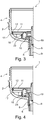
- a filter device 1 which can be designed as an oil or fuel filter, for example, a filter housing pot 2 and a screwable therewith and only in Fig. 1 indicated cover 3. Together these form a filter housing 4.
- a filter housing 4 In the filter housing 4 is a ring filter element 5 (cf. Fig. 2 ) arranged.
- the filter housing pot 2 has a central drainage channel 6, through which both water that has collected in a water collecting space 7 and all of the liquid in the filter housing pot 2 can be drained off when the filter is to be changed (see also Fig. 6 and 7th ).
- a drain screw 9, which has a driver contour 10, is rotatably arranged in the drain channel 6 via a second thread 8.
- the ring filter element 5 has a lower end plate 11 with an outer ring seal 12 that interacts with the filter housing pot 2 in the installed state and with a counter driver contour 13 that interacts with the driver contour 10 (cf. Fig. 5 ).
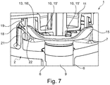
- the drain screw 9 is adjustable between at least three positions, as shown in FIG Figs. 1 to 4 is shown, namely between a lower position (see Figs. 1 and 2 ), in which the drain screw 9 tightly closes the drain channel 6, an intermediate position (cf. Fig. 3 ), in which the drain screw 9 releases the drain channel 6, but does not yet interact via its driver contour 10 with the counter driver contour 13 on the ring filter element side and, last but not least, an upper position (cf. Fig. 4 , 7th ), in which the drain screw 9 releases the drain channel 6 and interacts via its driver contour 10 with the counter driver contour 13 on the ring filter element side, whereby turning the drain screw 9 also causes the ring filter element 5 to turn.
- the drain screw 9 In the lower position, the drain screw 9 thus tightly closes the drain channel 6 via an annular seal 14.
- the drain screw 9 In the intermediate position, as this according to the Fig. 3 is shown, the drain screw 9 is already adjusted so far upwards that the seal 14 is no longer arranged tightly in the drain channel 6 and in this state, for example, water can be drained from the water collecting space 7.
- water or liquid can also be drained via the drainage channel 6, and at the same time when the drain screw 9 is rotated in its upper position via the driver contour 10 and counter-driver contour 13 that interact in this case, a rotation of the ring filter element 5 and thus also the ring seal 12 is released.
- the ring seal 12 seals, for example, the water collecting space 7 arranged below it from a raw or clean room arranged above and is elastically clamped between the lower end disk 11 and the filter housing pot 2.
- swelling and also sticking of the ring seal 12 to the lower end plate 11 and the filter housing pot 2 can occur, causing the loosening and removal of the Ring filter element 5 from the filter housing pot 2 is made difficult for a desired change.
- This can be counteracted with the drain screw 9 according to the invention, since this not only enables the function of the water or liquid drain, but also a twisting and thus loosening of the ring filter element 5 and at the same time also an axial adjustment of the same, as shown in FIG of the Fig. 4 is shown.
- driver contour 10 on the drain screw side has at least two, in particular axially and / or radially protruding, blades 15.
- the counter driver contour 13 has at least two stop elements 16 which, in the upper position of the drain screw 9, interact with the wings 15 of the drain screw-side driver contour 10 and at the same time also cause the ring filter element 5 to rotate when the drain screw 9 is rotated in the upper position.
- driver contour 10 on the drain screw side has at least two, in particular axially protruding, wedge-shaped drivers 15 ', while the counter-driver contour 13 has at least two likewise wedge-shaped drivers 16' (cf. Fig. 5 ), which in the upper position of the drain screw 9 interact with the drivers 15 'of the driver contour 10 on the drain screw side, as shown in FIG Fig. 7 is shown.
- the drivers 15 'and 16' are oriented opposite one another in the circumferential direction.
- Openings for a water separation are of course possible in the lower end disk 11, so that separated water can get into the water collecting space 7 arranged below the end disk 11.
- the ring filter element 5 is connected to the filter housing pot 2 via a first thread 18.
- a dome 19 protruding concentrically and axially from the lower end disk 11 of the ring filter element 15 has a free passage 20 (cf. Fig. 1 ) interrupted external thread, wherein at the same time axially protruding from the filter housing pot 2 and arranged as a hollow cylinder spring elements 21 are provided, on each of which an internal thread section designed complementary to the external thread is arranged and wherein the external thread and the internal thread together form the first thread 18.
- Each internal thread section extends over a longer circumferential section than a clearance 20, that is to say over a longer segment of a circle.
- the first thread 18 is opposite the second thread 8 between the drain screw 9 and the filter housing pot 2.
- the spring elements 21 also enable the ring filter element 5 to be inserted into the filter housing pot 2 from above, since in this case the spring elements 21 simply spring elastically radially outward. After interacting with the external thread on the dome 19, the spring elements 21 spring back radially inward and form the first thread 18. Both threads have sliding surfaces 22 to push the external thread over the internal thread.
- a total of eight spring elements 21, each with an internal thread section, are preferably provided.
- the external thread usually has a total of six free passages 20.
- the dome 19 and the external thread with its free passages 20 are preferably formed in one piece with the lower end plate 11, in particular as a common plastic injection-molded part, but made possible by high quality and inexpensive production on the one hand.
- the filter device 1 according to the invention it is possible for the first time, especially in the case of large ring filter elements 5, to replace them more easily, since the drain screw 9 according to the invention has a further function, namely that of rotating and thus also releasing the ring filter element 5 and pressing it out of the filter housing pot 2 becomes.
- the filter device 1 can optionally be designed as a hanging or as a standing filter, and according to the illustrations in FIGS Figs. 1 to 4 is designed as a hanging filter. Is it as a standing filter formed, the first thread 18 could also be arranged between an upper end disk (not shown) of the ring filter element 5 and the cover 3.
Landscapes
- Chemical & Material Sciences (AREA)
- Chemical Kinetics & Catalysis (AREA)
- Filtration Of Liquid (AREA)
Claims (10)
- Dispositif de filtration (1) avec un pot de boîtier de filtre (2) ainsi qu'avec un élément filtrant annulaire (5) disposé dans celui-ci,- dans lequel le pot de boîtier de filtre (2) présente un conduit de vidange (6) central, dans lequel une vis de vidange (9) est disposée, qui présente un contour d'entraînement (10),- dans lequel l'élément filtrant annulaire (5) présente un disque d'extrémité inférieur (11) avec un joint d'étanchéité annulaire (12) situé à l'extérieur et coopérant dans l'état monté avec le pot de boîtier de filtre (2) et un contour d'entraînement complémentaire (13) coopérant avec le contour d'entraînement (10),
caractérisé en ce- que la vis de vidange (9) peut être déplacée entre au moins trois positions, à savoir- une position inférieure, dans laquelle la vis de vidange (9) ferme le conduit de vidange (6) de manière étanche,- une position intermédiaire, dans laquelle la vis de vidange (9) libère le conduit de vidange (6) mais ne coopère pas encore avec le contour d'entraînement complémentaire (13) côté élément filtrant annulaire par l'intermédiaire de son contour d'entraînement (10),- une position supérieure, dans laquelle la vis de vidange (9) libère le conduit de vidange (6) et coopère avec le contour d'entraînement complémentaire (13) côté élément filtrant annulaire par l'intermédiaire de son contour d'entraînement (10), ce qui a pour effet qu'une rotation de la vis de vidange (9) provoque une rotation de l'élément filtrant annulaire (5). - Dispositif de filtration selon la revendication 1,
caractérisé en ce- que le contour d'entraînement (10) côté vis de vidange présente au moins deux ailettes (15), faisant saillie en particulier axialement et/ou radialement,- que le contour d'entraînement complémentaire (13) présente au moins deux éléments de butée (16), qui, dans la position supérieure de la vis de vidange (9), coopèrent avec les ailettes (15) du contour d'entraînement (10) côté vis de vidange. - Dispositif de filtration selon la revendication 1,
caractérisé en ce- que le contour d'entraînement (10) côté vis de vidange présente au moins deux entraîneurs (15') cunéiformes, faisant saillie en particulier axialement,- que le contour d'entraînement complémentaire (13) présente au moins deux entraîneurs (16') également cunéiformes, qui, dans la position supérieure de la vis de vidange (9), coopèrent avec les entraîneurs (15') du contour d'entraînement (10) côté vis de vidange. - Dispositif de filtration selon l'une quelconque des revendications 1 à 3,
caractérisé en ce
que la vis de vidange (9) présente un joint d'étanchéité annulaire (14), qui, dans la position inférieure de la vis de vidange (9), est disposé de manière étanche dans le conduit de vidange (6). - Dispositif de filtration selon l'une quelconque des revendications 1 à 4,
caractérisé en ce
que le pot de boîtier de filtre (2) présente une partie d'étanchéité cylindrique (17), dans laquelle le joint d'étanchéité annulaire (12) du disque d'extrémité inférieur (11) de l'élément filtrant annulaire (5) s'applique de manière étanche lorsque la vis de vidange (9) se trouve dans sa position inférieure et sa position intermédiaire. - Dispositif de filtration selon l'une quelconque des revendications 1 à 5,
caractérisé en ce- que l'élément filtrant annulaire (5) est relié au pot de boîtier de filtre (2) par l'intermédiaire d'un premier filetage (18),- qu'un dôme (19) faisant saillie de manière centrale et axiale du disque d'extrémité inférieur (11) de l'élément filtrant annulaire (5), avec un filetage mâle interrompu par des passages libres (20), et des éléments ressorts (21) faisant saillie axialement du pot de boîtier de filtre (2) et disposés en cylindre creux, sur lesquels est disposée respectivement une partie de filetage femelle réalisée de manière complémentaire au filetage mâle, sont prévus, dans lequel le filetage mâle et le filetage femelle forment conjointement le premier filetage (18),- que chaque partie de filetage femelle s'étend sur une partie périphérique plus longue qu'un passage libre (20),- que le premier filetage (18) est réalisé en sens contraire d'un second filetage (8) disposé entre le pot de boîtier de filtre (2) et la vis de vidange (9). - Dispositif de filtration selon la revendication 6,
caractérisé en ce
qu'au total huit éléments ressorts (21) sont pourvus respectivement d'une partie de filetage femelle. - Dispositif de filtration selon la revendication 6 ou 7,
caractérisé en ce
que le filetage mâle présente au total six passages libres (20). - Dispositif de filtration selon l'une quelconque des revendications 6 à 8,
caractérisé en ce
que le dôme (19) et le filetage mâle avec ses passages libres (20) sont réalisés d'une seule pièce avec le disque d'extrémité inférieur (11). - Dispositif de filtration selon l'une quelconque des revendications 1 à 9,
caractérisé en ce
que le dispositif de filtration (1) est réalisé en tant que filtre à carburant ou en tant que filtre à lubrifiant.
Applications Claiming Priority (2)
| Application Number | Priority Date | Filing Date | Title |
|---|---|---|---|
| DE102016221686.4A DE102016221686A1 (de) | 2016-11-04 | 2016-11-04 | Filtereinrichtung |
| PCT/EP2017/072105 WO2018082829A1 (fr) | 2016-11-04 | 2017-09-04 | Dispositif de filtration |
Publications (2)
| Publication Number | Publication Date |
|---|---|
| EP3535039A1 EP3535039A1 (fr) | 2019-09-11 |
| EP3535039B1 true EP3535039B1 (fr) | 2020-08-26 |
Family
ID=59930318
Family Applications (1)
| Application Number | Title | Priority Date | Filing Date |
|---|---|---|---|
| EP17771683.4A Active EP3535039B1 (fr) | 2016-11-04 | 2017-09-04 | Dispositif de filtration |
Country Status (4)
| Country | Link |
|---|---|
| US (1) | US20190282936A1 (fr) |
| EP (1) | EP3535039B1 (fr) |
| DE (1) | DE102016221686A1 (fr) |
| WO (1) | WO2018082829A1 (fr) |
Families Citing this family (2)
| Publication number | Priority date | Publication date | Assignee | Title |
|---|---|---|---|---|
| DE102019108958A1 (de) * | 2019-04-05 | 2020-10-08 | Hengst Se | Filter und Filtereinsatz dafür |
| DE102022106933A1 (de) | 2022-03-24 | 2023-09-28 | Mann+Hummel Gmbh | Filterelement, Filterelementeinheit und Filter |
Family Cites Families (10)
| Publication number | Priority date | Publication date | Assignee | Title |
|---|---|---|---|---|
| DE19707132A1 (de) | 1997-02-22 | 1998-08-27 | Mann & Hummel Filter | Filter |
| JP4190383B2 (ja) * | 2003-10-01 | 2008-12-03 | トヨタ紡織株式会社 | 流体フィルタ及びそのドレン機構、流体フィルタに使用されるドレン用冶具並びに流体フィルタのドレン方法 |
| DE202007003355U1 (de) | 2007-03-05 | 2008-07-10 | Mann + Hummel Gmbh | Filtergehäuse |
| US8501003B2 (en) * | 2007-10-17 | 2013-08-06 | Caterpillar Inc. | Canister filter system with drain that cooperates with filter element |
| DE102007062221A1 (de) * | 2007-12-21 | 2009-06-25 | Mahle International Gmbh | Flüssigkeitsfilter |
| US8241493B2 (en) * | 2008-06-16 | 2012-08-14 | Baldwin Filters, Inc. | Filter with ejection mechanism |
| DE102010064180A1 (de) * | 2010-12-27 | 2012-06-28 | Mahle International Gmbh | Filtereinrichtung |
| DE102012000876C5 (de) | 2012-01-19 | 2014-10-02 | Mann+Hummel Gmbh | Flüssigkeitsfilter und Filterelement eines Flüssigkeitsfilters |
| DE102014216637A1 (de) * | 2014-08-21 | 2016-02-25 | Mahle International Gmbh | Filtereinrichtung |
| DE102015207231B4 (de) * | 2015-04-21 | 2017-09-14 | Mahle International Gmbh | Filtereinrichtung |
-
2016
- 2016-11-04 DE DE102016221686.4A patent/DE102016221686A1/de not_active Withdrawn
-
2017
- 2017-09-04 US US16/347,341 patent/US20190282936A1/en not_active Abandoned
- 2017-09-04 EP EP17771683.4A patent/EP3535039B1/fr active Active
- 2017-09-04 WO PCT/EP2017/072105 patent/WO2018082829A1/fr unknown
Non-Patent Citations (1)
| Title |
|---|
| None * |
Also Published As
| Publication number | Publication date |
|---|---|
| EP3535039A1 (fr) | 2019-09-11 |
| US20190282936A1 (en) | 2019-09-19 |
| DE102016221686A1 (de) | 2018-05-09 |
| WO2018082829A1 (fr) | 2018-05-11 |
Similar Documents
| Publication | Publication Date | Title |
|---|---|---|
| EP3345670B1 (fr) | Dispositif de filtration | |
| EP3329979B1 (fr) | Boitier pour un filtre et élément filtrant | |
| EP2229232B1 (fr) | Filtre à liquides | |
| EP2445605B1 (fr) | Dispositif de filtration | |
| DE102009024699A1 (de) | Filtereinrichtung | |
| EP2201993A1 (fr) | Filtre à fluide | |
| EP3538776B1 (fr) | Phare avec un boitier et une vis de reglage | |
| EP3535039B1 (fr) | Dispositif de filtration | |
| EP2337618B1 (fr) | Dispositif filtrant | |
| DE102010046528A1 (de) | Fluidfilter | |
| EP3498359B1 (fr) | Élément filtrant et dispositif filtrant correspondant | |
| EP1731210A1 (fr) | Dispositif de filtration avec un élément filtrant | |
| EP3458175B1 (fr) | Dispositif de filtration | |
| EP3544714B1 (fr) | Élément filtrant et filtre pour fluides muni d'une bague baïonnette rotative | |
| EP3120914A1 (fr) | Dispositif de filtration | |
| WO2018065138A1 (fr) | Filtre à liquide | |
| DE102018221256A1 (de) | Filterelement für eine Filtereinrichtung | |
| EP2803399B1 (fr) | Filtre de liquide | |
| DE102018202718A1 (de) | Ringdichtung aus elastischem Kunststoff | |
| DE102017217600A1 (de) | Filtereinrichtung | |
| DE102021209281A1 (de) | Schraube für ein Kraftfahrzeug | |
| EP2831472B1 (fr) | Système pour la constitution d'une étanchéité | |
| DE102011112182A1 (de) | Anordnung einer Bremsscheibe an einer Radnabe | |
| DE102017003578A1 (de) | Vorrichtung zum Austauschen eines Filterelements |
Legal Events
| Date | Code | Title | Description |
|---|---|---|---|
| STAA | Information on the status of an ep patent application or granted ep patent |
Free format text: STATUS: UNKNOWN |
|
| STAA | Information on the status of an ep patent application or granted ep patent |
Free format text: STATUS: THE INTERNATIONAL PUBLICATION HAS BEEN MADE |
|
| PUAI | Public reference made under article 153(3) epc to a published international application that has entered the european phase |
Free format text: ORIGINAL CODE: 0009012 |
|
| STAA | Information on the status of an ep patent application or granted ep patent |
Free format text: STATUS: REQUEST FOR EXAMINATION WAS MADE |
|
| 17P | Request for examination filed |
Effective date: 20190404 |
|
| AK | Designated contracting states |
Kind code of ref document: A1 Designated state(s): AL AT BE BG CH CY CZ DE DK EE ES FI FR GB GR HR HU IE IS IT LI LT LU LV MC MK MT NL NO PL PT RO RS SE SI SK SM TR |
|
| AX | Request for extension of the european patent |
Extension state: BA ME |
|
| DAV | Request for validation of the european patent (deleted) | ||
| DAX | Request for extension of the european patent (deleted) | ||
| GRAP | Despatch of communication of intention to grant a patent |
Free format text: ORIGINAL CODE: EPIDOSNIGR1 |
|
| STAA | Information on the status of an ep patent application or granted ep patent |
Free format text: STATUS: GRANT OF PATENT IS INTENDED |
|
| INTG | Intention to grant announced |
Effective date: 20200430 |
|
| GRAS | Grant fee paid |
Free format text: ORIGINAL CODE: EPIDOSNIGR3 |
|
| GRAA | (expected) grant |
Free format text: ORIGINAL CODE: 0009210 |
|
| STAA | Information on the status of an ep patent application or granted ep patent |
Free format text: STATUS: THE PATENT HAS BEEN GRANTED |
|
| AK | Designated contracting states |
Kind code of ref document: B1 Designated state(s): AL AT BE BG CH CY CZ DE DK EE ES FI FR GB GR HR HU IE IS IT LI LT LU LV MC MK MT NL NO PL PT RO RS SE SI SK SM TR |
|
| REG | Reference to a national code |
Ref country code: GB Ref legal event code: FG4D Free format text: NOT ENGLISH |
|
| REG | Reference to a national code |
Ref country code: CH Ref legal event code: EP |
|
| REG | Reference to a national code |
Ref country code: AT Ref legal event code: REF Ref document number: 1305817 Country of ref document: AT Kind code of ref document: T Effective date: 20200915 |
|
| REG | Reference to a national code |
Ref country code: IE Ref legal event code: FG4D Free format text: LANGUAGE OF EP DOCUMENT: GERMAN |
|
| REG | Reference to a national code |
Ref country code: DE Ref legal event code: R096 Ref document number: 502017006958 Country of ref document: DE |
|
| REG | Reference to a national code |
Ref country code: LT Ref legal event code: MG4D |
|
| PG25 | Lapsed in a contracting state [announced via postgrant information from national office to epo] |
Ref country code: LT Free format text: LAPSE BECAUSE OF FAILURE TO SUBMIT A TRANSLATION OF THE DESCRIPTION OR TO PAY THE FEE WITHIN THE PRESCRIBED TIME-LIMIT Effective date: 20200826 Ref country code: FI Free format text: LAPSE BECAUSE OF FAILURE TO SUBMIT A TRANSLATION OF THE DESCRIPTION OR TO PAY THE FEE WITHIN THE PRESCRIBED TIME-LIMIT Effective date: 20200826 Ref country code: BG Free format text: LAPSE BECAUSE OF FAILURE TO SUBMIT A TRANSLATION OF THE DESCRIPTION OR TO PAY THE FEE WITHIN THE PRESCRIBED TIME-LIMIT Effective date: 20201126 Ref country code: HR Free format text: LAPSE BECAUSE OF FAILURE TO SUBMIT A TRANSLATION OF THE DESCRIPTION OR TO PAY THE FEE WITHIN THE PRESCRIBED TIME-LIMIT Effective date: 20200826 Ref country code: PT Free format text: LAPSE BECAUSE OF FAILURE TO SUBMIT A TRANSLATION OF THE DESCRIPTION OR TO PAY THE FEE WITHIN THE PRESCRIBED TIME-LIMIT Effective date: 20201228 Ref country code: SE Free format text: LAPSE BECAUSE OF FAILURE TO SUBMIT A TRANSLATION OF THE DESCRIPTION OR TO PAY THE FEE WITHIN THE PRESCRIBED TIME-LIMIT Effective date: 20200826 Ref country code: GR Free format text: LAPSE BECAUSE OF FAILURE TO SUBMIT A TRANSLATION OF THE DESCRIPTION OR TO PAY THE FEE WITHIN THE PRESCRIBED TIME-LIMIT Effective date: 20201127 Ref country code: NO Free format text: LAPSE BECAUSE OF FAILURE TO SUBMIT A TRANSLATION OF THE DESCRIPTION OR TO PAY THE FEE WITHIN THE PRESCRIBED TIME-LIMIT Effective date: 20201126 |
|
| REG | Reference to a national code |
Ref country code: NL Ref legal event code: MP Effective date: 20200826 |
|
| PG25 | Lapsed in a contracting state [announced via postgrant information from national office to epo] |
Ref country code: PL Free format text: LAPSE BECAUSE OF FAILURE TO SUBMIT A TRANSLATION OF THE DESCRIPTION OR TO PAY THE FEE WITHIN THE PRESCRIBED TIME-LIMIT Effective date: 20200826 Ref country code: RS Free format text: LAPSE BECAUSE OF FAILURE TO SUBMIT A TRANSLATION OF THE DESCRIPTION OR TO PAY THE FEE WITHIN THE PRESCRIBED TIME-LIMIT Effective date: 20200826 Ref country code: NL Free format text: LAPSE BECAUSE OF FAILURE TO SUBMIT A TRANSLATION OF THE DESCRIPTION OR TO PAY THE FEE WITHIN THE PRESCRIBED TIME-LIMIT Effective date: 20200826 Ref country code: LV Free format text: LAPSE BECAUSE OF FAILURE TO SUBMIT A TRANSLATION OF THE DESCRIPTION OR TO PAY THE FEE WITHIN THE PRESCRIBED TIME-LIMIT Effective date: 20200826 Ref country code: IS Free format text: LAPSE BECAUSE OF FAILURE TO SUBMIT A TRANSLATION OF THE DESCRIPTION OR TO PAY THE FEE WITHIN THE PRESCRIBED TIME-LIMIT Effective date: 20201226 |
|
| REG | Reference to a national code |
Ref country code: DE Ref legal event code: R119 Ref document number: 502017006958 Country of ref document: DE |
|
| PG25 | Lapsed in a contracting state [announced via postgrant information from national office to epo] |
Ref country code: CZ Free format text: LAPSE BECAUSE OF FAILURE TO SUBMIT A TRANSLATION OF THE DESCRIPTION OR TO PAY THE FEE WITHIN THE PRESCRIBED TIME-LIMIT Effective date: 20200826 Ref country code: DK Free format text: LAPSE BECAUSE OF FAILURE TO SUBMIT A TRANSLATION OF THE DESCRIPTION OR TO PAY THE FEE WITHIN THE PRESCRIBED TIME-LIMIT Effective date: 20200826 Ref country code: RO Free format text: LAPSE BECAUSE OF FAILURE TO SUBMIT A TRANSLATION OF THE DESCRIPTION OR TO PAY THE FEE WITHIN THE PRESCRIBED TIME-LIMIT Effective date: 20200826 Ref country code: EE Free format text: LAPSE BECAUSE OF FAILURE TO SUBMIT A TRANSLATION OF THE DESCRIPTION OR TO PAY THE FEE WITHIN THE PRESCRIBED TIME-LIMIT Effective date: 20200826 Ref country code: SM Free format text: LAPSE BECAUSE OF FAILURE TO SUBMIT A TRANSLATION OF THE DESCRIPTION OR TO PAY THE FEE WITHIN THE PRESCRIBED TIME-LIMIT Effective date: 20200826 |
|
| REG | Reference to a national code |
Ref country code: CH Ref legal event code: PL |
|
| PG25 | Lapsed in a contracting state [announced via postgrant information from national office to epo] |
Ref country code: AL Free format text: LAPSE BECAUSE OF FAILURE TO SUBMIT A TRANSLATION OF THE DESCRIPTION OR TO PAY THE FEE WITHIN THE PRESCRIBED TIME-LIMIT Effective date: 20200826 Ref country code: ES Free format text: LAPSE BECAUSE OF FAILURE TO SUBMIT A TRANSLATION OF THE DESCRIPTION OR TO PAY THE FEE WITHIN THE PRESCRIBED TIME-LIMIT Effective date: 20200826 Ref country code: MC Free format text: LAPSE BECAUSE OF FAILURE TO SUBMIT A TRANSLATION OF THE DESCRIPTION OR TO PAY THE FEE WITHIN THE PRESCRIBED TIME-LIMIT Effective date: 20200826 |
|
| REG | Reference to a national code |
Ref country code: BE Ref legal event code: MM Effective date: 20200930 |
|
| PG25 | Lapsed in a contracting state [announced via postgrant information from national office to epo] |
Ref country code: SK Free format text: LAPSE BECAUSE OF FAILURE TO SUBMIT A TRANSLATION OF THE DESCRIPTION OR TO PAY THE FEE WITHIN THE PRESCRIBED TIME-LIMIT Effective date: 20200826 Ref country code: LU Free format text: LAPSE BECAUSE OF NON-PAYMENT OF DUE FEES Effective date: 20200904 |
|
| PLBE | No opposition filed within time limit |
Free format text: ORIGINAL CODE: 0009261 |
|
| STAA | Information on the status of an ep patent application or granted ep patent |
Free format text: STATUS: NO OPPOSITION FILED WITHIN TIME LIMIT |
|
| PG25 | Lapsed in a contracting state [announced via postgrant information from national office to epo] |
Ref country code: FR Free format text: LAPSE BECAUSE OF NON-PAYMENT OF DUE FEES Effective date: 20201026 Ref country code: IT Free format text: LAPSE BECAUSE OF FAILURE TO SUBMIT A TRANSLATION OF THE DESCRIPTION OR TO PAY THE FEE WITHIN THE PRESCRIBED TIME-LIMIT Effective date: 20200826 Ref country code: DE Free format text: LAPSE BECAUSE OF NON-PAYMENT OF DUE FEES Effective date: 20210401 |
|
| 26N | No opposition filed |
Effective date: 20210527 |
|
| PG25 | Lapsed in a contracting state [announced via postgrant information from national office to epo] |
Ref country code: SI Free format text: LAPSE BECAUSE OF FAILURE TO SUBMIT A TRANSLATION OF THE DESCRIPTION OR TO PAY THE FEE WITHIN THE PRESCRIBED TIME-LIMIT Effective date: 20200826 Ref country code: IE Free format text: LAPSE BECAUSE OF NON-PAYMENT OF DUE FEES Effective date: 20200904 Ref country code: LI Free format text: LAPSE BECAUSE OF NON-PAYMENT OF DUE FEES Effective date: 20200930 Ref country code: CH Free format text: LAPSE BECAUSE OF NON-PAYMENT OF DUE FEES Effective date: 20200930 Ref country code: BE Free format text: LAPSE BECAUSE OF NON-PAYMENT OF DUE FEES Effective date: 20200930 |
|
| GBPC | Gb: european patent ceased through non-payment of renewal fee |
Effective date: 20210904 |
|
| PG25 | Lapsed in a contracting state [announced via postgrant information from national office to epo] |
Ref country code: TR Free format text: LAPSE BECAUSE OF FAILURE TO SUBMIT A TRANSLATION OF THE DESCRIPTION OR TO PAY THE FEE WITHIN THE PRESCRIBED TIME-LIMIT Effective date: 20200826 Ref country code: MT Free format text: LAPSE BECAUSE OF FAILURE TO SUBMIT A TRANSLATION OF THE DESCRIPTION OR TO PAY THE FEE WITHIN THE PRESCRIBED TIME-LIMIT Effective date: 20200826 Ref country code: CY Free format text: LAPSE BECAUSE OF FAILURE TO SUBMIT A TRANSLATION OF THE DESCRIPTION OR TO PAY THE FEE WITHIN THE PRESCRIBED TIME-LIMIT Effective date: 20200826 |
|
| PG25 | Lapsed in a contracting state [announced via postgrant information from national office to epo] |
Ref country code: MK Free format text: LAPSE BECAUSE OF FAILURE TO SUBMIT A TRANSLATION OF THE DESCRIPTION OR TO PAY THE FEE WITHIN THE PRESCRIBED TIME-LIMIT Effective date: 20200826 |
|
| PG25 | Lapsed in a contracting state [announced via postgrant information from national office to epo] |
Ref country code: GB Free format text: LAPSE BECAUSE OF NON-PAYMENT OF DUE FEES Effective date: 20210904 |
|
| REG | Reference to a national code |
Ref country code: AT Ref legal event code: MM01 Ref document number: 1305817 Country of ref document: AT Kind code of ref document: T Effective date: 20220904 |
|
| PG25 | Lapsed in a contracting state [announced via postgrant information from national office to epo] |
Ref country code: AT Free format text: LAPSE BECAUSE OF NON-PAYMENT OF DUE FEES Effective date: 20220904 |