EP2754183B1 - Module solaire, installation photovoltaïque et procédé pour faire fonctionner une telle installation - Google Patents
Module solaire, installation photovoltaïque et procédé pour faire fonctionner une telle installation Download PDFInfo
- Publication number
- EP2754183B1 EP2754183B1 EP12751475.0A EP12751475A EP2754183B1 EP 2754183 B1 EP2754183 B1 EP 2754183B1 EP 12751475 A EP12751475 A EP 12751475A EP 2754183 B1 EP2754183 B1 EP 2754183B1
- Authority
- EP
- European Patent Office
- Prior art keywords
- solar module
- switch
- sensor
- solar
- photovoltaic system
- Prior art date
- Legal status (The legal status is an assumption and is not a legal conclusion. Google has not performed a legal analysis and makes no representation as to the accuracy of the status listed.)
- Active
Links
- 238000000034 method Methods 0.000 title claims description 6
- 238000001514 detection method Methods 0.000 claims description 3
- 230000000737 periodic effect Effects 0.000 claims description 2
- 230000004044 response Effects 0.000 claims description 2
- 238000005070 sampling Methods 0.000 claims description 2
- 238000011156 evaluation Methods 0.000 description 4
- 230000008901 benefit Effects 0.000 description 3
- 238000010586 diagram Methods 0.000 description 3
- 238000013459 approach Methods 0.000 description 2
- 238000004891 communication Methods 0.000 description 2
- 238000012423 maintenance Methods 0.000 description 2
- 241001465754 Metazoa Species 0.000 description 1
- 230000009471 action Effects 0.000 description 1
- 230000004913 activation Effects 0.000 description 1
- 238000006243 chemical reaction Methods 0.000 description 1
- 230000001419 dependent effect Effects 0.000 description 1
- 230000006866 deterioration Effects 0.000 description 1
- 238000011161 development Methods 0.000 description 1
- 230000018109 developmental process Effects 0.000 description 1
- 238000004146 energy storage Methods 0.000 description 1
- 238000012854 evaluation process Methods 0.000 description 1
- 231100001261 hazardous Toxicity 0.000 description 1
- 238000010248 power generation Methods 0.000 description 1
- 230000008569 process Effects 0.000 description 1
- 238000012545 processing Methods 0.000 description 1
- 230000001681 protective effect Effects 0.000 description 1
- 230000005855 radiation Effects 0.000 description 1
- 239000000523 sample Substances 0.000 description 1
- 238000000926 separation method Methods 0.000 description 1
- 238000012360 testing method Methods 0.000 description 1
- 230000001960 triggered effect Effects 0.000 description 1
Images
Classifications
-
- H—ELECTRICITY
- H01—ELECTRIC ELEMENTS
- H01L—SEMICONDUCTOR DEVICES NOT COVERED BY CLASS H10
- H01L31/00—Semiconductor devices sensitive to infrared radiation, light, electromagnetic radiation of shorter wavelength or corpuscular radiation and specially adapted either for the conversion of the energy of such radiation into electrical energy or for the control of electrical energy by such radiation; Processes or apparatus specially adapted for the manufacture or treatment thereof or of parts thereof; Details thereof
- H01L31/02—Details
- H01L31/02016—Circuit arrangements of general character for the devices
- H01L31/02019—Circuit arrangements of general character for the devices for devices characterised by at least one potential jump barrier or surface barrier
- H01L31/02021—Circuit arrangements of general character for the devices for devices characterised by at least one potential jump barrier or surface barrier for solar cells
-
- Y—GENERAL TAGGING OF NEW TECHNOLOGICAL DEVELOPMENTS; GENERAL TAGGING OF CROSS-SECTIONAL TECHNOLOGIES SPANNING OVER SEVERAL SECTIONS OF THE IPC; TECHNICAL SUBJECTS COVERED BY FORMER USPC CROSS-REFERENCE ART COLLECTIONS [XRACs] AND DIGESTS
- Y02—TECHNOLOGIES OR APPLICATIONS FOR MITIGATION OR ADAPTATION AGAINST CLIMATE CHANGE
- Y02E—REDUCTION OF GREENHOUSE GAS [GHG] EMISSIONS, RELATED TO ENERGY GENERATION, TRANSMISSION OR DISTRIBUTION
- Y02E10/00—Energy generation through renewable energy sources
- Y02E10/50—Photovoltaic [PV] energy
Definitions
- the invention relates to a solar module with a plurality of solar cells connected to an output terminal, as part of a photovoltaic system, which has a switchable connection with an external load. It further relates to a photovoltaic system with a plurality of such solar modules and a method for operating such.
- Photovoltaic power generation plants have been installed on many residential and commercial buildings in recent years. Usually in these a larger number of solar modules is raised on the plant roof, while usually a larger number of components in one or more strands is summarized. Within the single string, the modules are connected in series, so that the current through the string is indeed constant, but the total voltage increases in proportion to the number of solar modules used. Typical total voltages thus reach orders of magnitude of up to 1 kV DC at currents around 15 A. The energy generated, however, can not be fed directly into the public grid, but it must first take place a conversion of DC into AC voltage. For this purpose, a so-called. Inverter is needed, which is preferably installed in residential buildings in the basement of the building.
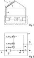
- a photovoltaic system 1 which is composed of a plurality of solar modules 3, each with a junction box 5, on the roof and an inverter 7 in the basement power cable 9, the sufficient requirements z. B. have to comply with high voltage safety.
- an external load 11 such as a power supply or an in-house energy storage
- a switching device 13 is provided, with about a network separation of the photovoltaic system in the event of a fire can be made.
- the system outlined above may pose potential hazards to humans, animals and property.
- the media has been discussing a threat of high voltages in the event of fire.
- the basis of the problem is that the solar modules usually produce a voltage as long as light is incident on them. If, in the event of fire, a building is disconnected from the power supply by the fire department, the AC output of the inverter is de-energized, but the area between the modules and the inverter still carries the DC high voltage. If the cable z. B. damaged by fire or mechanical impact, the high voltage is at the cable ends freely and can lead to electric shock when the fire department enters the building during a firefighting. A similar situation may occur when maintenance is required on parts of the plant.
- the invention provides a solar module comprising a protective switching device of a photovoltaic system with the features of claim 1.
- Advantageous developments of the inventive concept are the subject of the dependent claims.
- a photovoltaic system and a method for operating such is proposed in the context of the invention.
- An essential concept of the invention consists in the provision of at least one integrated switch in the solar module, which is arranged and designed for the output connection from a voltage-free idle state to a non-voltage-free operating state or from a non-voltage-free operating state to a voltage-free idle state. Furthermore, it belongs to the invention To provide a sensor for detecting a the connection state of the photovoltaic system with the external load characterizing size in or on the solar module. Furthermore, it is essential that the solar module has a switch control connected on the input side to the sensor, which is designed for periodically scanning the sensor output and for actuating the switch or the switch for switching the output connection to the operating state in response to the detection of a connected state of the photovoltaic system ,
- the senor is designed as a current sensor for detecting a current flow in the solar module in the connected state of the photovoltaic system.
- a voltage sensor connected to an input terminal of the switch controller is provided for detecting a voltage supplied by the solar module when exposed to sunlight.
- the switch control and optionally the sensor is connected via a supply connection in the solar module, so that the power supply is self-sufficient in the solar module.
- the switch may be provided in connection with the last-mentioned embodiment or independently of this that the switch has a normally-on switch, in particular MOSFET, for the voltage-free maintenance of the high-impedance idle state.
- a further embodiment of the proposed solution provides that the switch control has a timer for determining the, in particular adjustable, time intervals of the periodic sampling of the probe.
- suitable setting of the timer can be a compatible compromise between the conflicting goals, by the To minimize sensing and evaluation process conditional interruptions of the energy supplying plant operation, and perform the scans as often as possible with regard to the reliability.
- the solar module is provided with a first switch arranged in parallel with the output terminal and a second switch connected in series with the solar cells, the switch controller being designed to actuate the first and second switches according to a predetermined switching algorithm.
- a photovoltaic system which has solar modules of the type described above, operated such that each within the solar modules is periodically sensed whether the photovoltaic system is in the state connected to the load, and not connected without voltage when detecting a connected state of the output of each solar module becomes.
- Fig. 2 shows in a greatly reduced representation as essential components of a solar module according to the invention 3, a plurality of solar cell strings 4 in a series circuit with two terminals 9a, 9b, in which a first switch 15a in series with the solar cell strings 4 and a second switch 15b parallel to these is provided in a bypass line 9c between the terminals 9a and 9b.
- a switch control 17 is provided, which is the input side for receiving a (not specified here) sensor signal S is formed.
- the solar module behaves in the non-active state as a short circuit and not, as usual, a power source or the series connection of multiple power sources. This can be achieved by the switch 15b parallel to the output terminals of the module.
- the also drawn switch 15a is not mandatory. Alternatively, it is possible to also leave switch 15b open and switch 15a to open. This would make the module from the outside high impedance and also voltage-free.
- the module checks to what extent the application of the voltage resulting from solar irradiation to the external terminals 9a, 9b results in a current, ie to what extent an external consumer is connected.
- the module will resume normal operation by the switch controller 17 closing the switch 15a and opening the switch 15b.
- the supply of the controller is done via the solar cells of the module, see below.
- the entire process is repeated cyclically z. B. at intervals. Ie. the module regularly interrupts his regular work to see to what extent an external consumer is still available. If this is no longer the case, the module immediately goes into the safety state.
- the entire photovoltaic system can be switched off by interrupting the DC line alone.
- the resumption of the function happens equally by simply switching on the load.
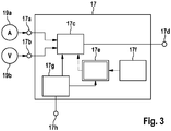
- Fig. 3 shows the structure of an embodiment of the switch control 17 of a solar module 3 according to the invention in a schematic diagram.
- the switch controller 17 has a first sensor signal input terminal 17a, through which it is connected to a current sensor 19a for sensing a current flow in a solar cell string, and a second sensor signal input terminal 17b, through which it passes with a voltmeter 19b for detecting a Solar radiation caused module voltage is connected.
- the first and second sensor signal input terminals 17a, 17b are in turn connected to a sensor signal evaluation stage 17c, which as a result of processing a predetermined sensor signal evaluation algorithm at predetermined time intervals at a control signal output terminal 17d provides a switch control signal.
- the operation of the evaluation stage 17 is controlled by a controller 17e, which in turn is triggered by an internal timer 17f and supplied as well as the evaluation stage 17e by a power supply stage 17g, which in turn via a power supply terminal 17h for self-supply with a (not shown) tap point of the corresponding Solar module is connected.
Landscapes
- Engineering & Computer Science (AREA)
- Life Sciences & Earth Sciences (AREA)
- Sustainable Development (AREA)
- Sustainable Energy (AREA)
- Physics & Mathematics (AREA)
- Condensed Matter Physics & Semiconductors (AREA)
- Electromagnetism (AREA)
- General Physics & Mathematics (AREA)
- Computer Hardware Design (AREA)
- Microelectronics & Electronic Packaging (AREA)
- Power Engineering (AREA)
- Photovoltaic Devices (AREA)
Claims (9)
- Module solaire (3) comprenant une pluralité de cellules solaires (4) reliées à une borne de sortie (9a ; 9b), lequel est conçu en tant qu'élément constitutif d'une installation photovoltaïque (1), laquelle possède une liaison commutable (13) avec une charge externe (11),
le module solaire possédant au moins un commutateur intégré (15a ; 15b) qui est disposé et conçu pour commuter la borne de sortie d'un état de repos à haute impédance ou hors tension en un état de fonctionnement à basse impédance ou non hors tension,
une sonde (19a) destinée à détecter une grandeur qui caractérise l'état de liaison de l'installation photovoltaïque avec la charge externe et
une commande de commutateur (17) dont l'entrée est reliée à la sonde, laquelle est conçue pour un palpage périodique de la sortie de la sonde et pour un actionnement du commutateur ou des commutateurs en vue de l'inversion de la borne de sortie dans l'état de fonctionnement en réaction à la détection d'un état connecté de l'installation photovoltaïque. - Module solaire selon la revendication 1, la sonde (19a) étant réalisée sous la forme d'une sonde de courant servant à la détection d'un flux de courant dans le module solaire (4) à l'état connecté de l'installation photovoltaïque (1).
- Module solaire selon la revendication 1 ou 2, une sonde de tension (19b) reliée à une borne d'entrée de la commande de commutateur (17) étant en plus présente pour détecter une tension délivrée par le module solaire en présence du rayonnement solaire.
- Module solaire selon l'une des revendications précédentes, la commande de commutateur (17) et, en option, la ou chaque sonde (19a ; 19b) sont connectées par le biais d'une borne d'alimentation (17h) dans le module solaire (4), de sorte que l'alimentation électrique s'effectue de manière autonome dans le module solaire.
- Module solaire selon l'une des revendications précédentes, le commutateur (15a ; 15b) possédant un commutateur à conduction autonome, notamment un MOSFET, servant au maintien en l'absence de tension de l'état de repos hors tension.
- Module solaire selon l'une des revendications précédentes, la commande de commutateur (17) possédant un temporisateur (17f) destiné à définir les intervalles de temps, notamment réglables, du palpage périodique de la sonde (19a).
- Module solaire selon l'une des revendications précédentes, comprenant un premier commutateur (15b) monté en parallèle avec la borne de sortie et un deuxième commutateur (15a) branché en série avec les cellules solaires, la commande de commutateur (17) étant configurée pour actionner le premier et le deuxième commutateur conformément à un algorithme de commutation prédéfini.
- Installation photovoltaïque (1) comprenant une pluralité de modules solaires (4) selon l'une des revendications précédentes, un onduleur (7) et une liaison commutable (13) avec une charge externe (11), la liaison étant commutable, notamment du côté de la sortie de l'onduleur.
- Procédé pour faire fonctionner une installation photovoltaïque (1) comprenant une pluralité de modules solaires (4) selon l'une des revendications précédentes, un onduleur (7) et une liaison commutable (13) avec une charge externe (11), un sondage étant réalisé périodiquement à chaque fois à l'intérieur des modules solaires afin de déterminer si l'installation photovoltaïque se trouve dans l'état connecté à la charge, et si un état connecté est constaté, la sortie de chaque module solaire est commutée à haute impédance ou hors tension.
Applications Claiming Priority (2)
| Application Number | Priority Date | Filing Date | Title |
|---|---|---|---|
| DE102011082162A DE102011082162A1 (de) | 2011-09-06 | 2011-09-06 | Solarmodul, Photovoltaikanlage und Verfahren zum Betrieb einer solchen |
| PCT/EP2012/065855 WO2013034403A1 (fr) | 2011-09-06 | 2012-08-14 | Module solaire, installation photovoltaïque et procédé pour faire fonctionner une telle installation |
Publications (2)
| Publication Number | Publication Date |
|---|---|
| EP2754183A1 EP2754183A1 (fr) | 2014-07-16 |
| EP2754183B1 true EP2754183B1 (fr) | 2017-06-28 |
Family
ID=46754962
Family Applications (1)
| Application Number | Title | Priority Date | Filing Date |
|---|---|---|---|
| EP12751475.0A Active EP2754183B1 (fr) | 2011-09-06 | 2012-08-14 | Module solaire, installation photovoltaïque et procédé pour faire fonctionner une telle installation |
Country Status (3)
| Country | Link |
|---|---|
| EP (1) | EP2754183B1 (fr) |
| DE (1) | DE102011082162A1 (fr) |
| WO (1) | WO2013034403A1 (fr) |
Families Citing this family (1)
| Publication number | Priority date | Publication date | Assignee | Title |
|---|---|---|---|---|
| CN117477622B (zh) * | 2023-10-27 | 2024-05-03 | 三钧线缆(无锡)有限公司 | 一种储能线束的保护控制方法及系统 |
Family Cites Families (11)
| Publication number | Priority date | Publication date | Assignee | Title |
|---|---|---|---|---|
| SE0302453D0 (sv) | 2003-09-16 | 2003-09-16 | Solarit Ab | A module, a converter, a node, and a system |
| DE102005018173B4 (de) | 2005-04-19 | 2009-05-14 | Swiontek, Karl, Dipl.-Ing. | Schalteinrichtung zur sicheren Betriebsunterbrechung von Photovoltaikanlagen |
| US7442849B2 (en) | 2005-12-30 | 2008-10-28 | 3M Innovative Properties Company | Thin film delivery system and method of manufacture |
| DE102006060815B4 (de) | 2006-09-21 | 2013-05-29 | Solarworld Innovations Gmbh | Solarenergieerzeugungsanlage |
| DE202007002077U1 (de) * | 2007-02-13 | 2008-04-03 | Dehm, Christian | Notabschaltung für Solarstromanlagen |
| DE102008004675B3 (de) | 2007-10-12 | 2009-03-05 | Fraunhofer-Gesellschaft zur Förderung der angewandten Forschung e.V. | Steuerbare Umschaltvorrichtung für ein Solarmodul |
| DE102008003272A1 (de) | 2008-01-05 | 2009-07-09 | Hans-Hermann Hunfeld | Überwachungseinheit für Photovoltaik-Module |
| US20090207543A1 (en) | 2008-02-14 | 2009-08-20 | Independent Power Systems, Inc. | System and method for fault detection and hazard prevention in photovoltaic source and output circuits |
| DE102008029491B4 (de) | 2008-06-20 | 2010-06-17 | Robert Bosch Gmbh | Schutzvorrichtung für eine Solaranlage und Solaranlage |
| FR2940548A3 (fr) * | 2008-12-23 | 2010-06-25 | Transenergie | Dispositif de controle d'une installation de production d'energie electrique et installation de production d'energie electrique mettant en oeuvre un tel dispositif |
| WO2010078303A2 (fr) | 2008-12-29 | 2010-07-08 | Atonometrics, Inc. | Système d'arrêt de sécurité électrique et dispositifs pour modules photovoltaïques |
-
2011
- 2011-09-06 DE DE102011082162A patent/DE102011082162A1/de not_active Withdrawn
-
2012
- 2012-08-14 EP EP12751475.0A patent/EP2754183B1/fr active Active
- 2012-08-14 WO PCT/EP2012/065855 patent/WO2013034403A1/fr active Application Filing
Non-Patent Citations (1)
| Title |
|---|
| None * |
Also Published As
| Publication number | Publication date |
|---|---|
| WO2013034403A1 (fr) | 2013-03-14 |
| EP2754183A1 (fr) | 2014-07-16 |
| DE102011082162A1 (de) | 2013-03-07 |
Similar Documents
| Publication | Publication Date | Title |
|---|---|---|
| DE10107600C1 (de) | Verfahren zum Betreiben eines photovoltaischen Solarmoduls und photovoltaischer Solarmodul | |
| EP2954558B1 (fr) | Installation photovoltaïque | |
| EP2745327B1 (fr) | Boîte de connexions pour un panneau solaire, pourvue d'un circuit de protection | |
| WO2009006879A2 (fr) | Installation photovoltaïque | |
| EP1720241A2 (fr) | Generateur photovoltaique avec interrupteur thermique | |
| EP2256822A2 (fr) | Installation de commutation de sécurité pour installations solaires | |
| EP2567405A1 (fr) | Procédé pour limiter la tension de générateur d'une installation photovoltaïque en cas de danger et installation photovoltaïque correspondante | |
| WO2007006564A2 (fr) | Dispositif de surveillance de panneaux photovoltaiques | |
| DE102010054354A1 (de) | Verfahren zur Abschaltung einer Photovoltaikanlage sowie Photovoltaikanlage | |
| EP2101391A2 (fr) | Dispositif de protection pour panneaux solaires | |
| DE202011110074U1 (de) | Modulbypassschaltung für ein Photovoltaikmodul | |
| DE202007001648U1 (de) | Vorrichtung zur Spannungsfreischaltung von Photovoltaikanlagen zur Ermöglichung des Einsatzes von Löschmitteln und zur sicheren Freischaltung von Netzen | |
| EP2647052B1 (fr) | Installation photovoltaïque | |
| DE102010037760B4 (de) | Vorrichtung und Verfahren zur Spannungsfreischaltung elektrischer, in einem Gebäude oder Gebäudekomplex verlaufender Leitungen einer Photovoltaikanlage, Verwendung der Vorrichtung sowie System mit der Vorrichtung und einer Photovoltaikanlage | |
| DE102010049293B3 (de) | Anordnung zum sicheren Außerbetriebsetzen von Photovoltaikanlagen | |
| EP2754183B1 (fr) | Module solaire, installation photovoltaïque et procédé pour faire fonctionner une telle installation | |
| DE102013018950A1 (de) | Generator-Anschlusskasten für erhöhte elektrische Sicherheit und reduzierte Wartungskosten bei PV-Kraftwerken | |
| DE202007009783U1 (de) | Fotovoltaikanlage | |
| DE102010023262A1 (de) | Solarkraftwerk mit erhöhter Lebensdauer | |
| DE102011014759B4 (de) | Photovoltaikanlage mit einer Sicherungs-Vorrichtung zur Sicherung der Photovoltaikmodule der Photovoltaikanlage | |
| DE102013210714A1 (de) | Photovoltaikanlage | |
| WO2013034336A2 (fr) | Dispositif coupe-circuit, installation photovoltaïque et procédé de fonctionnement associé | |
| DE202012000324U1 (de) | Anordnung zur sicheren Abschaltung der DC-Seite einer Photovoltaik-Anlage | |
| DE102013112362A1 (de) | Photovoltaikanlage sowie Betriebsverfahren und Wechselrichter für eine Photovoltaikanlage | |
| DE102010032978A1 (de) | System zur Sicherheits- und Notausschaltung für Anlagen in der Solartechnik zur umfangreichen Spannungs- und Stromfreiheit auf der gesamten Anlagenfläche. IPS Notausschaltung |
Legal Events
| Date | Code | Title | Description |
|---|---|---|---|
| PUAI | Public reference made under article 153(3) epc to a published international application that has entered the european phase |
Free format text: ORIGINAL CODE: 0009012 |
|
| 17P | Request for examination filed |
Effective date: 20140407 |
|
| AK | Designated contracting states |
Kind code of ref document: A1 Designated state(s): AL AT BE BG CH CY CZ DE DK EE ES FI FR GB GR HR HU IE IS IT LI LT LU LV MC MK MT NL NO PL PT RO RS SE SI SK SM TR |
|
| DAX | Request for extension of the european patent (deleted) | ||
| GRAP | Despatch of communication of intention to grant a patent |
Free format text: ORIGINAL CODE: EPIDOSNIGR1 |
|
| RAP1 | Party data changed (applicant data changed or rights of an application transferred) |
Owner name: SMA SOLAR TECHNOLOGY AG |
|
| INTG | Intention to grant announced |
Effective date: 20170306 |
|
| GRAS | Grant fee paid |
Free format text: ORIGINAL CODE: EPIDOSNIGR3 |
|
| GRAA | (expected) grant |
Free format text: ORIGINAL CODE: 0009210 |
|
| AK | Designated contracting states |
Kind code of ref document: B1 Designated state(s): AL AT BE BG CH CY CZ DE DK EE ES FI FR GB GR HR HU IE IS IT LI LT LU LV MC MK MT NL NO PL PT RO RS SE SI SK SM TR |
|
| REG | Reference to a national code |
Ref country code: GB Ref legal event code: FG4D Free format text: NOT ENGLISH |
|
| REG | Reference to a national code |
Ref country code: CH Ref legal event code: EP |
|
| REG | Reference to a national code |
Ref country code: AT Ref legal event code: REF Ref document number: 905550 Country of ref document: AT Kind code of ref document: T Effective date: 20170715 |
|
| REG | Reference to a national code |
Ref country code: IE Ref legal event code: FG4D Free format text: LANGUAGE OF EP DOCUMENT: GERMAN |
|
| REG | Reference to a national code |
Ref country code: DE Ref legal event code: R096 Ref document number: 502012010666 Country of ref document: DE |
|
| REG | Reference to a national code |
Ref country code: FR Ref legal event code: PLFP Year of fee payment: 6 |
|
| REG | Reference to a national code |
Ref country code: NL Ref legal event code: FP |
|
| PG25 | Lapsed in a contracting state [announced via postgrant information from national office to epo] |
Ref country code: GR Free format text: LAPSE BECAUSE OF FAILURE TO SUBMIT A TRANSLATION OF THE DESCRIPTION OR TO PAY THE FEE WITHIN THE PRESCRIBED TIME-LIMIT Effective date: 20170929 Ref country code: LT Free format text: LAPSE BECAUSE OF FAILURE TO SUBMIT A TRANSLATION OF THE DESCRIPTION OR TO PAY THE FEE WITHIN THE PRESCRIBED TIME-LIMIT Effective date: 20170628 Ref country code: FI Free format text: LAPSE BECAUSE OF FAILURE TO SUBMIT A TRANSLATION OF THE DESCRIPTION OR TO PAY THE FEE WITHIN THE PRESCRIBED TIME-LIMIT Effective date: 20170628 Ref country code: HR Free format text: LAPSE BECAUSE OF FAILURE TO SUBMIT A TRANSLATION OF THE DESCRIPTION OR TO PAY THE FEE WITHIN THE PRESCRIBED TIME-LIMIT Effective date: 20170628 Ref country code: NO Free format text: LAPSE BECAUSE OF FAILURE TO SUBMIT A TRANSLATION OF THE DESCRIPTION OR TO PAY THE FEE WITHIN THE PRESCRIBED TIME-LIMIT Effective date: 20170928 |
|
| REG | Reference to a national code |
Ref country code: LT Ref legal event code: MG4D |
|
| PG25 | Lapsed in a contracting state [announced via postgrant information from national office to epo] |
Ref country code: RS Free format text: LAPSE BECAUSE OF FAILURE TO SUBMIT A TRANSLATION OF THE DESCRIPTION OR TO PAY THE FEE WITHIN THE PRESCRIBED TIME-LIMIT Effective date: 20170628 Ref country code: BG Free format text: LAPSE BECAUSE OF FAILURE TO SUBMIT A TRANSLATION OF THE DESCRIPTION OR TO PAY THE FEE WITHIN THE PRESCRIBED TIME-LIMIT Effective date: 20170928 Ref country code: LV Free format text: LAPSE BECAUSE OF FAILURE TO SUBMIT A TRANSLATION OF THE DESCRIPTION OR TO PAY THE FEE WITHIN THE PRESCRIBED TIME-LIMIT Effective date: 20170628 Ref country code: SE Free format text: LAPSE BECAUSE OF FAILURE TO SUBMIT A TRANSLATION OF THE DESCRIPTION OR TO PAY THE FEE WITHIN THE PRESCRIBED TIME-LIMIT Effective date: 20170628 |
|
| PG25 | Lapsed in a contracting state [announced via postgrant information from national office to epo] |
Ref country code: SK Free format text: LAPSE BECAUSE OF FAILURE TO SUBMIT A TRANSLATION OF THE DESCRIPTION OR TO PAY THE FEE WITHIN THE PRESCRIBED TIME-LIMIT Effective date: 20170628 Ref country code: EE Free format text: LAPSE BECAUSE OF FAILURE TO SUBMIT A TRANSLATION OF THE DESCRIPTION OR TO PAY THE FEE WITHIN THE PRESCRIBED TIME-LIMIT Effective date: 20170628 Ref country code: CZ Free format text: LAPSE BECAUSE OF FAILURE TO SUBMIT A TRANSLATION OF THE DESCRIPTION OR TO PAY THE FEE WITHIN THE PRESCRIBED TIME-LIMIT Effective date: 20170628 Ref country code: RO Free format text: LAPSE BECAUSE OF FAILURE TO SUBMIT A TRANSLATION OF THE DESCRIPTION OR TO PAY THE FEE WITHIN THE PRESCRIBED TIME-LIMIT Effective date: 20170628 |
|
| PG25 | Lapsed in a contracting state [announced via postgrant information from national office to epo] |
Ref country code: IS Free format text: LAPSE BECAUSE OF FAILURE TO SUBMIT A TRANSLATION OF THE DESCRIPTION OR TO PAY THE FEE WITHIN THE PRESCRIBED TIME-LIMIT Effective date: 20171028 Ref country code: ES Free format text: LAPSE BECAUSE OF FAILURE TO SUBMIT A TRANSLATION OF THE DESCRIPTION OR TO PAY THE FEE WITHIN THE PRESCRIBED TIME-LIMIT Effective date: 20170628 Ref country code: SM Free format text: LAPSE BECAUSE OF FAILURE TO SUBMIT A TRANSLATION OF THE DESCRIPTION OR TO PAY THE FEE WITHIN THE PRESCRIBED TIME-LIMIT Effective date: 20170628 Ref country code: PL Free format text: LAPSE BECAUSE OF FAILURE TO SUBMIT A TRANSLATION OF THE DESCRIPTION OR TO PAY THE FEE WITHIN THE PRESCRIBED TIME-LIMIT Effective date: 20170628 |
|
| REG | Reference to a national code |
Ref country code: DE Ref legal event code: R097 Ref document number: 502012010666 Country of ref document: DE Ref country code: CH Ref legal event code: PL |
|
| PG25 | Lapsed in a contracting state [announced via postgrant information from national office to epo] |
Ref country code: MC Free format text: LAPSE BECAUSE OF FAILURE TO SUBMIT A TRANSLATION OF THE DESCRIPTION OR TO PAY THE FEE WITHIN THE PRESCRIBED TIME-LIMIT Effective date: 20170628 |
|
| PG25 | Lapsed in a contracting state [announced via postgrant information from national office to epo] |
Ref country code: CH Free format text: LAPSE BECAUSE OF NON-PAYMENT OF DUE FEES Effective date: 20170831 Ref country code: DK Free format text: LAPSE BECAUSE OF FAILURE TO SUBMIT A TRANSLATION OF THE DESCRIPTION OR TO PAY THE FEE WITHIN THE PRESCRIBED TIME-LIMIT Effective date: 20170628 Ref country code: LI Free format text: LAPSE BECAUSE OF NON-PAYMENT OF DUE FEES Effective date: 20170831 |
|
| PLBE | No opposition filed within time limit |
Free format text: ORIGINAL CODE: 0009261 |
|
| STAA | Information on the status of an ep patent application or granted ep patent |
Free format text: STATUS: NO OPPOSITION FILED WITHIN TIME LIMIT |
|
| REG | Reference to a national code |
Ref country code: IE Ref legal event code: MM4A |
|
| 26N | No opposition filed |
Effective date: 20180329 |
|
| PG25 | Lapsed in a contracting state [announced via postgrant information from national office to epo] |
Ref country code: LU Free format text: LAPSE BECAUSE OF NON-PAYMENT OF DUE FEES Effective date: 20170814 |
|
| PG25 | Lapsed in a contracting state [announced via postgrant information from national office to epo] |
Ref country code: IE Free format text: LAPSE BECAUSE OF NON-PAYMENT OF DUE FEES Effective date: 20170814 |
|
| REG | Reference to a national code |
Ref country code: FR Ref legal event code: PLFP Year of fee payment: 7 |
|
| PG25 | Lapsed in a contracting state [announced via postgrant information from national office to epo] |
Ref country code: SI Free format text: LAPSE BECAUSE OF FAILURE TO SUBMIT A TRANSLATION OF THE DESCRIPTION OR TO PAY THE FEE WITHIN THE PRESCRIBED TIME-LIMIT Effective date: 20170628 |
|
| PG25 | Lapsed in a contracting state [announced via postgrant information from national office to epo] |
Ref country code: MT Free format text: LAPSE BECAUSE OF FAILURE TO SUBMIT A TRANSLATION OF THE DESCRIPTION OR TO PAY THE FEE WITHIN THE PRESCRIBED TIME-LIMIT Effective date: 20170628 |
|
| REG | Reference to a national code |
Ref country code: AT Ref legal event code: MM01 Ref document number: 905550 Country of ref document: AT Kind code of ref document: T Effective date: 20170814 |
|
| PG25 | Lapsed in a contracting state [announced via postgrant information from national office to epo] |
Ref country code: AT Free format text: LAPSE BECAUSE OF NON-PAYMENT OF DUE FEES Effective date: 20170814 |
|
| PG25 | Lapsed in a contracting state [announced via postgrant information from national office to epo] |
Ref country code: HU Free format text: LAPSE BECAUSE OF FAILURE TO SUBMIT A TRANSLATION OF THE DESCRIPTION OR TO PAY THE FEE WITHIN THE PRESCRIBED TIME-LIMIT; INVALID AB INITIO Effective date: 20120814 |
|
| PG25 | Lapsed in a contracting state [announced via postgrant information from national office to epo] |
Ref country code: CY Free format text: LAPSE BECAUSE OF NON-PAYMENT OF DUE FEES Effective date: 20170628 |
|
| PG25 | Lapsed in a contracting state [announced via postgrant information from national office to epo] |
Ref country code: MK Free format text: LAPSE BECAUSE OF FAILURE TO SUBMIT A TRANSLATION OF THE DESCRIPTION OR TO PAY THE FEE WITHIN THE PRESCRIBED TIME-LIMIT Effective date: 20170628 |
|
| PG25 | Lapsed in a contracting state [announced via postgrant information from national office to epo] |
Ref country code: TR Free format text: LAPSE BECAUSE OF FAILURE TO SUBMIT A TRANSLATION OF THE DESCRIPTION OR TO PAY THE FEE WITHIN THE PRESCRIBED TIME-LIMIT Effective date: 20170628 |
|
| PG25 | Lapsed in a contracting state [announced via postgrant information from national office to epo] |
Ref country code: PT Free format text: LAPSE BECAUSE OF FAILURE TO SUBMIT A TRANSLATION OF THE DESCRIPTION OR TO PAY THE FEE WITHIN THE PRESCRIBED TIME-LIMIT Effective date: 20170628 |
|
| PG25 | Lapsed in a contracting state [announced via postgrant information from national office to epo] |
Ref country code: AL Free format text: LAPSE BECAUSE OF FAILURE TO SUBMIT A TRANSLATION OF THE DESCRIPTION OR TO PAY THE FEE WITHIN THE PRESCRIBED TIME-LIMIT Effective date: 20170628 |
|
| PGFP | Annual fee paid to national office [announced via postgrant information from national office to epo] |
Ref country code: NL Payment date: 20230823 Year of fee payment: 12 |
|
| PGFP | Annual fee paid to national office [announced via postgrant information from national office to epo] |
Ref country code: IT Payment date: 20230831 Year of fee payment: 12 Ref country code: GB Payment date: 20230824 Year of fee payment: 12 |
|
| PGFP | Annual fee paid to national office [announced via postgrant information from national office to epo] |
Ref country code: FR Payment date: 20230821 Year of fee payment: 12 Ref country code: DE Payment date: 20230822 Year of fee payment: 12 Ref country code: BE Payment date: 20230822 Year of fee payment: 12 |