EP2101391A2 - Dispositif de protection pour panneaux solaires - Google Patents
Dispositif de protection pour panneaux solaires Download PDFInfo
- Publication number
- EP2101391A2 EP2101391A2 EP20090002608 EP09002608A EP2101391A2 EP 2101391 A2 EP2101391 A2 EP 2101391A2 EP 20090002608 EP20090002608 EP 20090002608 EP 09002608 A EP09002608 A EP 09002608A EP 2101391 A2 EP2101391 A2 EP 2101391A2
- Authority
- EP
- European Patent Office
- Prior art keywords
- solar panel
- safety circuit
- contactor
- circuit according
- bypass
- Prior art date
- Legal status (The legal status is an assumption and is not a legal conclusion. Google has not performed a legal analysis and makes no representation as to the accuracy of the status listed.)
- Withdrawn
Links
- 210000000056 organ Anatomy 0.000 abstract 1
- 230000001419 dependent effect Effects 0.000 description 3
- 230000004913 activation Effects 0.000 description 1
- 230000015572 biosynthetic process Effects 0.000 description 1
- 230000006378 damage Effects 0.000 description 1
- 238000011161 development Methods 0.000 description 1
- 230000018109 developmental process Effects 0.000 description 1
- 230000005611 electricity Effects 0.000 description 1
- 230000001681 protective effect Effects 0.000 description 1
- 230000005855 radiation Effects 0.000 description 1
Images

Classifications
-
- H—ELECTRICITY
- H02—GENERATION; CONVERSION OR DISTRIBUTION OF ELECTRIC POWER
- H02H—EMERGENCY PROTECTIVE CIRCUIT ARRANGEMENTS
- H02H7/00—Emergency protective circuit arrangements specially adapted for specific types of electric machines or apparatus or for sectionalised protection of cable or line systems, and effecting automatic switching in the event of an undesired change from normal working conditions
- H02H7/20—Emergency protective circuit arrangements specially adapted for specific types of electric machines or apparatus or for sectionalised protection of cable or line systems, and effecting automatic switching in the event of an undesired change from normal working conditions for electronic equipment
-
- H—ELECTRICITY
- H01—ELECTRIC ELEMENTS
- H01L—SEMICONDUCTOR DEVICES NOT COVERED BY CLASS H10
- H01L31/00—Semiconductor devices sensitive to infrared radiation, light, electromagnetic radiation of shorter wavelength or corpuscular radiation and specially adapted either for the conversion of the energy of such radiation into electrical energy or for the control of electrical energy by such radiation; Processes or apparatus specially adapted for the manufacture or treatment thereof or of parts thereof; Details thereof
- H01L31/02—Details
- H01L31/02016—Circuit arrangements of general character for the devices
- H01L31/02019—Circuit arrangements of general character for the devices for devices characterised by at least one potential jump barrier or surface barrier
- H01L31/02021—Circuit arrangements of general character for the devices for devices characterised by at least one potential jump barrier or surface barrier for solar cells
-
- Y—GENERAL TAGGING OF NEW TECHNOLOGICAL DEVELOPMENTS; GENERAL TAGGING OF CROSS-SECTIONAL TECHNOLOGIES SPANNING OVER SEVERAL SECTIONS OF THE IPC; TECHNICAL SUBJECTS COVERED BY FORMER USPC CROSS-REFERENCE ART COLLECTIONS [XRACs] AND DIGESTS
- Y02—TECHNOLOGIES OR APPLICATIONS FOR MITIGATION OR ADAPTATION AGAINST CLIMATE CHANGE
- Y02E—REDUCTION OF GREENHOUSE GAS [GHG] EMISSIONS, RELATED TO ENERGY GENERATION, TRANSMISSION OR DISTRIBUTION
- Y02E10/00—Energy generation through renewable energy sources
- Y02E10/50—Photovoltaic [PV] energy
- Y02E10/56—Power conversion systems, e.g. maximum power point trackers
Definitions
- the invention relates to a safety circuit for a solar panel.
- the solar panel has two connections, each to a supply line to a consumer.
- a bypass, which is arranged between the two terminals and in front of the supply lines has at least one closer.
- Solar panels are used as a solar energy source and provide a useful power to connected consumers when exposed to sunlight. Frequently, several solar modules are combined to form a solar panel, thus increasing the generated useful current. Today, solar panels are increasingly being installed on private and public rooftops and serve as an additional source of energy for private and public households.
- the fire brigade In the case of house or apartment fires, the fire brigade must ensure that the place of use is switched off and de-energized so that, for example, when using extinguishing agents, no injuries are caused by electric shocks. For a solar panel to be safely removed from the home network, a shutdown must be performed directly on the solar panel, otherwise there may still be a voltage between leads.
- the emergency services often do not have the time to switch off the solar system on the roof directly, because often the way to the roof is blocked or the time for a shutdown from the roof is too short.
- the house network is in the Cellar by the main switch and de-energized switched. A backup of the solar panel is then not guaranteed.
- the invention relates to a safety circuit for a solar panel, wherein the solar panel has two connections to a supply line to a consumer, with a bypass, which is arranged between the two terminals and in front of the supply lines and having at least one closer, wherein in each of the two leads an opener is arranged.
- the at least one closer in the bypass of the solar panel and located in each supply line of the solar panel opener can be actuated simultaneously by an actuator.
- the at least one closer and the openers are arranged in a contactor and actuated by a contactor designed as a relay actuator.
- a particularly preferred embodiment is characterized in that at least two NO contacts are connected in series in the bypass.
- bypass is arranged in the local vicinity of the solar panel. It is particularly advantageous if the NC and NO are arranged with your actuator in close proximity to the terminals of the solar panel.
- the actuator is clearly remotely controlled by the solar panel.
- a particular embodiment of the invention shows that the actuating member can be controlled via an emergency stop switch.
- the main advantage of the invention is the simultaneous switching of the NC and NO of the safety circuit for the solar panel. This causes, for example in the case of a fire, a quick shutdown of the solar panel from the home network and consumers.
- a circuit of the NC and NO contact via a contactor has the consequence that for switching off the solar panel designed as a contactor relay actuator can be controlled via an emergency stop switch.
- the emergency stop switch may advantageously be located in the vicinity of the main switch of the power supply of a home, which should advantageously be the controlled contactor in the vicinity of the solar panel. As a result, the supply lines between the solar panel and contactor are very short and only represent a very low risk of voltage flashovers.
- a solar panel 1 usually consists of a plurality of solar modules 1a, 1b, 1c.
- Fig. 1 discloses a solar panel 1 with two series-connected solar modules 1b, 1c. Parallel to the series-connected solar modules 1 b, 1 c, a third solar module 1 a is arranged. All located in the solar panel solar modules 1a, 1b, 1c are contacted via two outputs 11 and provide solar radiation electrical energy.
- Fig. 2 discloses a circuit according to the invention for safe shutdown of the solar panel 1.
- a contactor 2 is connected in close proximity to the solar panel 1.
- the contactor 2 is controlled by a control unit 4, that is switched on and off.
- the control unit 4 can be advantageously mounted there, where the entire power supply (for example, a house) housed and over Fuses and switches is secured. This is often a basement room or an extra control room.
- the consumers 3 are connected. As a consumer 3 here is also a mostly necessary inverter to look at.
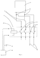
- Fig. 3 shows a detailed structure of a safety circuit.
- the solar panel 1 is connected via outputs 11 to the main terminals of a contactor 2, the contactor 2 in this embodiment, two NO contacts 23 and two NC 22 includes.
- Normally open contacts 23 are contacts which are open in the initial state and close a current path after actuation.
- an opener 22 contacts are here referred to, which are closed in the initial state.
- the opener 22 and closer 23 are actuated via a contactor designed as a relay 21 actuator. If the contactor relay 21 is supplied with power, the contactor relay 21 picks up and at the same time closes the make contacts 23 and opens the openers 22.
- the closer 23 are connected in parallel to the solar panel 1 in a bypass 5 and close the solar panel 1 briefly when the contactor relay 21 is driven.
- two closers 23 are connected in series in the bypass 5. This causes a better closing and opening behavior. Since only half the voltage is applied to each NO contact, the formation of electric arcs is made more difficult. It is possible to install more or less than two closer 23 in the bypass 5. This is dependent on the possible output voltage of the solar panel 1. If the closer 23 have been closed by the contactor relay 21, the solar panel 1 is short-circuited. Through the bypass currents can flow up to, for example, 60A.
- the Voltage at the outputs of a solar panel for a detached house can be up to, for example, 1,000 volts.
- an opener 22 is present in each supply line 31.
- both openers 22 are integrated in the contactor 2 and can be actuated via the contactor relay 21. If the contactor relay 21 is activated, the openers 22 open the current paths and prevent the feeding of current into the solar panel 1, for example, by a battery. Due to the common arrangement of the closer 23 and opener 22 in a contactor 2, a simultaneous opening of the opener 22 and closing the closer 23 in the bypass 5 can be realized by the activation of the contactor relay 21. The solar panel 1 is then short-circuited and can not feed electricity into the consumer. There is no voltage drop in the attached after the contactor 2 leads 31 longer possible.
- the lines between solar panel 1 and contactor 2 should be as short as possible.
- an external auxiliary power supply 42 which is connected via an emergency stop switch 41 to the contactor relay 21.
- the emergency stop switch 41 may be installed adjacent to the main power supply switch of a house. Thus, in the case of fire in addition to the main switch at the same time the power supply of the solar panel 1 are interrupted.
Landscapes
- Engineering & Computer Science (AREA)
- Power Engineering (AREA)
- Life Sciences & Earth Sciences (AREA)
- Sustainable Development (AREA)
- Sustainable Energy (AREA)
- Physics & Mathematics (AREA)
- Condensed Matter Physics & Semiconductors (AREA)
- Electromagnetism (AREA)
- General Physics & Mathematics (AREA)
- Computer Hardware Design (AREA)
- Microelectronics & Electronic Packaging (AREA)
- Protection Of Static Devices (AREA)
Applications Claiming Priority (1)
| Application Number | Priority Date | Filing Date | Title |
|---|---|---|---|
| DE200810014129 DE102008014129B4 (de) | 2008-03-13 | 2008-03-13 | Schutzvorrichtung für Solarpanels |
Publications (1)
| Publication Number | Publication Date |
|---|---|
| EP2101391A2 true EP2101391A2 (fr) | 2009-09-16 |
Family
ID=40732239
Family Applications (1)
| Application Number | Title | Priority Date | Filing Date |
|---|---|---|---|
| EP20090002608 Withdrawn EP2101391A2 (fr) | 2008-03-13 | 2009-02-25 | Dispositif de protection pour panneaux solaires |
Country Status (2)
| Country | Link |
|---|---|
| EP (1) | EP2101391A2 (fr) |
| DE (1) | DE102008014129B4 (fr) |
Cited By (13)
| Publication number | Priority date | Publication date | Assignee | Title |
|---|---|---|---|---|
| FR2956533A1 (fr) * | 2010-02-16 | 2011-08-19 | Cegelec Sud Est | Installation electrique comprenant des moyens generateurs de courant continu comportant au moins un module photovoltaique |
| WO2011135239A1 (fr) * | 2010-04-30 | 2011-11-03 | Augier Sa | Dispositif de sécurité pour panneaux photovoltaiques |
| WO2011138319A1 (fr) * | 2010-05-03 | 2011-11-10 | Sma Solar Technology Ag | Procédé pour limiter la tension de générateur d'une installation photovoltaïque en cas de danger et installation photovoltaïque correspondante |
| EP2390981A1 (fr) * | 2010-05-27 | 2011-11-30 | Schneider Electric Industries SAS | Dispositif de mise en sécurité d'une installation de génération d'énergie électrique et procédé de mise en oeuvre d'un tel dispositif |
| EP2432026A1 (fr) * | 2010-09-21 | 2012-03-21 | MS ENERGIES Société privée à responsabilité limitée | Installation photovoltaïque avec protection contre les dangers d'électrocution en cas d'incendie et boîtier de sécurité pour une telle installation |
| FR2970375A1 (fr) * | 2011-01-11 | 2012-07-13 | Philippe Dumas | Mise en securite electrique des installations de production d'energie photovoltaique |
| DE102011017362A1 (de) * | 2011-04-16 | 2012-10-18 | Adensis Gmbh | Drei-Schalter Überspannungsschutz |
| WO2012172087A1 (fr) * | 2011-06-15 | 2012-12-20 | Mersen France Sb Sas | Court-circuiteur pour installation de production d'énergie électrique |
| ITTO20110616A1 (it) * | 2011-07-13 | 2013-01-14 | Ehw Res S A S | Sistema per la messa in sicurezza di impianti solari. |
| DE102011114499A1 (de) | 2011-09-29 | 2013-04-04 | Andreas Walther | Schaltvorrichtung zum Unterbrechen einer elektrischen Spannungsversorgung |
| EP2643914A4 (fr) * | 2010-11-22 | 2016-04-20 | D B Bones Pty Ltd | Système destiné à isoler des parties d'un réseau d'alimentation électrique |
| CN102263395B (zh) * | 2010-05-27 | 2016-11-30 | 施耐德电器工业公司 | 发电装置的安全断开设备以及实现这样一种设备的方法 |
| EP2456034A3 (fr) * | 2010-11-19 | 2017-01-11 | Kostal Industrie Elektrik GmbH | Installation photovoltaïque et module photovoltaïque |
Families Citing this family (4)
| Publication number | Priority date | Publication date | Assignee | Title |
|---|---|---|---|---|
| DE102009019831A1 (de) * | 2009-05-04 | 2010-11-11 | Voltwerk Electronics Gmbh | Schaltungsanordnung |
| DE202010008494U1 (de) | 2010-09-09 | 2010-12-02 | Sailer, Roland | Photovoltaikmodul und photovoltaische Anlage |
| DE102010037418A1 (de) | 2010-09-09 | 2012-03-15 | Roland Sailer | Photovoltaikmodul und photovoltaische Anlage |
| EP2637193A1 (fr) | 2012-03-08 | 2013-09-11 | Eaton Industries GmbH | Dispositif de réenclenchement motorisé |
Citations (1)
| Publication number | Priority date | Publication date | Assignee | Title |
|---|---|---|---|---|
| US6051954A (en) | 1997-05-30 | 2000-04-18 | Canon Kabushiki Kaisha | Charge control apparatus |
Family Cites Families (2)
| Publication number | Priority date | Publication date | Assignee | Title |
|---|---|---|---|---|
| DE102005018173B4 (de) * | 2005-04-19 | 2009-05-14 | Swiontek, Karl, Dipl.-Ing. | Schalteinrichtung zur sicheren Betriebsunterbrechung von Photovoltaikanlagen |
| DE202006007613U1 (de) * | 2006-05-11 | 2006-08-17 | Beck, Manfred | Fotovoltaikanlage und Brandschutzsicherung hierfür |
-
2008
- 2008-03-13 DE DE200810014129 patent/DE102008014129B4/de not_active Expired - Fee Related
-
2009
- 2009-02-25 EP EP20090002608 patent/EP2101391A2/fr not_active Withdrawn
Patent Citations (1)
| Publication number | Priority date | Publication date | Assignee | Title |
|---|---|---|---|---|
| US6051954A (en) | 1997-05-30 | 2000-04-18 | Canon Kabushiki Kaisha | Charge control apparatus |
Cited By (26)
| Publication number | Priority date | Publication date | Assignee | Title |
|---|---|---|---|---|
| FR2956533A1 (fr) * | 2010-02-16 | 2011-08-19 | Cegelec Sud Est | Installation electrique comprenant des moyens generateurs de courant continu comportant au moins un module photovoltaique |
| WO2011135239A1 (fr) * | 2010-04-30 | 2011-11-03 | Augier Sa | Dispositif de sécurité pour panneaux photovoltaiques |
| FR2959619A1 (fr) * | 2010-04-30 | 2011-11-04 | Augier Sa | Dispositif de securite pour panneaux photovoltaiques destines aux erp |
| CN102939661A (zh) * | 2010-05-03 | 2013-02-20 | Sma太阳能技术股份公司 | 用于在危险情况下限制光伏设备发电机电压的方法和光伏设备 |
| WO2011138319A1 (fr) * | 2010-05-03 | 2011-11-10 | Sma Solar Technology Ag | Procédé pour limiter la tension de générateur d'une installation photovoltaïque en cas de danger et installation photovoltaïque correspondante |
| WO2011138314A1 (fr) * | 2010-05-03 | 2011-11-10 | Sma Solar Technology Ag | Procédé pour limiter la tension de générateur d'une installation photovoltaïque en cas de danger et installation photovoltaïque correspondante |
| CN102939661B (zh) * | 2010-05-03 | 2016-03-16 | Sma太阳能技术股份公司 | 用于在危险情况下限制光伏设备发电机电压的方法和光伏设备 |
| US8837098B2 (en) | 2010-05-03 | 2014-09-16 | Sma Solar Technology Ag | Method for limiting the generator voltage of a photovoltaic installation in case of danger and photovoltaic installation |
| CN102263395A (zh) * | 2010-05-27 | 2011-11-30 | 施耐德电器工业公司 | 发电装置的安全断开设备以及实现这样一种设备的方法 |
| FR2960711A1 (fr) * | 2010-05-27 | 2011-12-02 | Schneider Electric Ind Sas | Dispositif de mise en securite d'une installation de generation d'energie electrique et procede de mise en oeuvre d'un tel dispositif |
| CN102263395B (zh) * | 2010-05-27 | 2016-11-30 | 施耐德电器工业公司 | 发电装置的安全断开设备以及实现这样一种设备的方法 |
| EP2390981A1 (fr) * | 2010-05-27 | 2011-11-30 | Schneider Electric Industries SAS | Dispositif de mise en sécurité d'une installation de génération d'énergie électrique et procédé de mise en oeuvre d'un tel dispositif |
| EP2432026A1 (fr) * | 2010-09-21 | 2012-03-21 | MS ENERGIES Société privée à responsabilité limitée | Installation photovoltaïque avec protection contre les dangers d'électrocution en cas d'incendie et boîtier de sécurité pour une telle installation |
| EP2456034A3 (fr) * | 2010-11-19 | 2017-01-11 | Kostal Industrie Elektrik GmbH | Installation photovoltaïque et module photovoltaïque |
| EP2643914A4 (fr) * | 2010-11-22 | 2016-04-20 | D B Bones Pty Ltd | Système destiné à isoler des parties d'un réseau d'alimentation électrique |
| FR2970375A1 (fr) * | 2011-01-11 | 2012-07-13 | Philippe Dumas | Mise en securite electrique des installations de production d'energie photovoltaique |
| EP2511956A3 (fr) * | 2011-04-16 | 2015-12-16 | Adensis GmbH | Protection contre les surtensions à trois commutateurs pour une installation photovoltaïque |
| US8743521B2 (en) | 2011-04-16 | 2014-06-03 | Adensis Gmbh | Photovoltaic system with overvoltage protection |
| DE102011017362A1 (de) * | 2011-04-16 | 2012-10-18 | Adensis Gmbh | Drei-Schalter Überspannungsschutz |
| FR2976716A1 (fr) * | 2011-06-15 | 2012-12-21 | Mersen France Sb Sas | Court-circuiteur pour installation de production d'energie electrique |
| WO2012172087A1 (fr) * | 2011-06-15 | 2012-12-20 | Mersen France Sb Sas | Court-circuiteur pour installation de production d'énergie électrique |
| WO2013008084A1 (fr) * | 2011-07-13 | 2013-01-17 | Ehw-Research S.A.S. | Système permettant de mettre des centrales solaires en situation sûre |
| ITTO20110616A1 (it) * | 2011-07-13 | 2013-01-14 | Ehw Res S A S | Sistema per la messa in sicurezza di impianti solari. |
| DE102011114499A1 (de) | 2011-09-29 | 2013-04-04 | Andreas Walther | Schaltvorrichtung zum Unterbrechen einer elektrischen Spannungsversorgung |
| DE102011114499B4 (de) * | 2011-09-29 | 2015-05-13 | Andreas Walther | An der Außenhülle eines Gebäudes angeordnete Schaltvorrichtung zum Unterbrechen einer elektrischen Spannungsversorgung |
| DE102011114499B9 (de) * | 2011-09-29 | 2015-07-23 | Andreas Walther | An der Außenhülle eines Gebäudes angeordnete Schaltvorrichtung zum Unterbrechen einer elektrischen Spannungsversorgung |
Also Published As
| Publication number | Publication date |
|---|---|
| DE102008014129B4 (de) | 2009-12-31 |
| DE102008014129A1 (de) | 2009-09-24 |
Similar Documents
| Publication | Publication Date | Title |
|---|---|---|
| DE102008014129B4 (de) | Schutzvorrichtung für Solarpanels | |
| DE102009022508A1 (de) | Safety-Schaltanlage für Solaranlagen | |
| EP2048679B1 (fr) | Agencement de sectionneur à coupure en charge | |
| EP2745327B1 (fr) | Boîte de connexions pour un panneau solaire, pourvue d'un circuit de protection | |
| EP1720241A2 (fr) | Generateur photovoltaique avec interrupteur thermique | |
| DE102007032605A1 (de) | Fotovoltaikanlage | |
| DE202007002077U1 (de) | Notabschaltung für Solarstromanlagen | |
| DE102010014548A1 (de) | Eletkrische Niederspannungs-Gebäudeinstallation | |
| DE202011109688U1 (de) | Sicherheitsgerichtete Konstruktion und Freischaltung von Photovoltaikanlagen und sicherheitsgerichtete Erdung von Löscheinrichtungen | |
| WO2015059195A1 (fr) | Système d'onduleur et système pv | |
| DE102010049293B3 (de) | Anordnung zum sicheren Außerbetriebsetzen von Photovoltaikanlagen | |
| EP2647052B1 (fr) | Installation photovoltaïque | |
| DE102013012578A9 (de) | Vorrichtung zum Absichern einer elektrischen Leitung | |
| WO2012136837A2 (fr) | Dispositif d'arrêt d'urgence d'une installation photovoltaïque | |
| DE102011018972B4 (de) | Solarmodulschutzvorrichtung | |
| DE102007016635A1 (de) | Vorrichtung und Verfahren zum Verteilen elektrischer Energie | |
| DE102011014759B4 (de) | Photovoltaikanlage mit einer Sicherungs-Vorrichtung zur Sicherung der Photovoltaikmodule der Photovoltaikanlage | |
| EP2456034A2 (fr) | Installation photovoltaïque et module photovoltaïque | |
| DE102010004395A1 (de) | Schaltungsanordnung zum Schutz von Photovoltaikmodulen | |
| DE102020101002A1 (de) | Umschaltvorrichtung der elektrischen versorgung einer last | |
| DE202007009783U1 (de) | Fotovoltaikanlage | |
| DE202008006007U1 (de) | Absicherungs- und Verteilereinheit für die Elektroinstallation in einer mobilen Wohneinrichtung, insbesondere einem Wohnwagen und/oder Wohnmobil und/oder Boot | |
| DE102010047077B3 (de) | Vorrichtung zur Abschaltung eines lokalen Stromerzeugers | |
| DE102006004182B3 (de) | Leistungswandler mit einer Schalteinrichtung | |
| EP2439829A2 (fr) | Agencement destiné à la mise hors service sécurisée d'installations photovoltaïques |
Legal Events
| Date | Code | Title | Description |
|---|---|---|---|
| PUAI | Public reference made under article 153(3) epc to a published international application that has entered the european phase |
Free format text: ORIGINAL CODE: 0009012 |
|
| AK | Designated contracting states |
Kind code of ref document: A2 Designated state(s): AT BE BG CH CY CZ DE DK EE ES FI FR GB GR HR HU IE IS IT LI LT LU LV MC MK MT NL NO PL PT RO SE SI SK TR |
|
| AX | Request for extension of the european patent |
Extension state: AL BA RS |
|
| RAP1 | Party data changed (applicant data changed or rights of an application transferred) |
Owner name: EATON INDUSTIES GMBH |
|
| RAP1 | Party data changed (applicant data changed or rights of an application transferred) |
Owner name: EATON INDUSTRIES GMBH |
|
| STAA | Information on the status of an ep patent application or granted ep patent |
Free format text: STATUS: THE APPLICATION IS DEEMED TO BE WITHDRAWN |
|
| 18D | Application deemed to be withdrawn |
Effective date: 20140902 |