EP2754006B1 - Dispositif de commande - Google Patents
Dispositif de commande Download PDFInfo
- Publication number
- EP2754006B1 EP2754006B1 EP12759056.0A EP12759056A EP2754006B1 EP 2754006 B1 EP2754006 B1 EP 2754006B1 EP 12759056 A EP12759056 A EP 12759056A EP 2754006 B1 EP2754006 B1 EP 2754006B1
- Authority
- EP
- European Patent Office
- Prior art keywords
- planar
- operator control
- operator
- control device
- components
- Prior art date
- Legal status (The legal status is an assumption and is not a legal conclusion. Google has not performed a legal analysis and makes no representation as to the accuracy of the status listed.)
- Active
Links
- 239000012790 adhesive layer Substances 0.000 claims description 4
- 239000003302 ferromagnetic material Substances 0.000 claims description 4
- 229910052751 metal Inorganic materials 0.000 claims description 4
- 239000002184 metal Substances 0.000 claims description 4
- 230000008878 coupling Effects 0.000 claims description 3
- 238000010168 coupling process Methods 0.000 claims description 3
- 238000005859 coupling reaction Methods 0.000 claims description 3
- 238000006073 displacement reaction Methods 0.000 claims description 3
- 238000005516 engineering process Methods 0.000 claims description 3
- 230000000295 complement effect Effects 0.000 claims description 2
- 230000004913 activation Effects 0.000 claims 3
- 230000005294 ferromagnetic effect Effects 0.000 description 5
- 238000009434 installation Methods 0.000 description 5
- 230000005291 magnetic effect Effects 0.000 description 5
- 239000004020 conductor Substances 0.000 description 4
- 239000003351 stiffener Substances 0.000 description 4
- 230000004907 flux Effects 0.000 description 3
- 229910000639 Spring steel Inorganic materials 0.000 description 2
- 239000010410 layer Substances 0.000 description 2
- 238000007639 printing Methods 0.000 description 2
- 230000007704 transition Effects 0.000 description 2
- BQCADISMDOOEFD-UHFFFAOYSA-N Silver Chemical compound [Ag] BQCADISMDOOEFD-UHFFFAOYSA-N 0.000 description 1
- 238000005452 bending Methods 0.000 description 1
- 239000000919 ceramic Substances 0.000 description 1
- 239000012141 concentrate Substances 0.000 description 1
- 230000001419 dependent effect Effects 0.000 description 1
- 230000000694 effects Effects 0.000 description 1
- 238000004049 embossing Methods 0.000 description 1
- 238000005530 etching Methods 0.000 description 1
- 238000009413 insulation Methods 0.000 description 1
- 239000004973 liquid crystal related substance Substances 0.000 description 1
- 238000004519 manufacturing process Methods 0.000 description 1
- 239000000463 material Substances 0.000 description 1
- 239000011159 matrix material Substances 0.000 description 1
- 238000000034 method Methods 0.000 description 1
- 230000005693 optoelectronics Effects 0.000 description 1
- 210000000056 organ Anatomy 0.000 description 1
- 230000008569 process Effects 0.000 description 1
- 230000009467 reduction Effects 0.000 description 1
- 229910052709 silver Inorganic materials 0.000 description 1
- 239000004332 silver Substances 0.000 description 1
- 239000000758 substrate Substances 0.000 description 1
Images


Classifications
-
- G—PHYSICS
- G05—CONTROLLING; REGULATING
- G05B—CONTROL OR REGULATING SYSTEMS IN GENERAL; FUNCTIONAL ELEMENTS OF SUCH SYSTEMS; MONITORING OR TESTING ARRANGEMENTS FOR SUCH SYSTEMS OR ELEMENTS
- G05B19/00—Programme-control systems
- G05B19/02—Programme-control systems electric
- G05B19/18—Numerical control [NC], i.e. automatically operating machines, in particular machine tools, e.g. in a manufacturing environment, so as to execute positioning, movement or co-ordinated operations by means of programme data in numerical form
- G05B19/402—Numerical control [NC], i.e. automatically operating machines, in particular machine tools, e.g. in a manufacturing environment, so as to execute positioning, movement or co-ordinated operations by means of programme data in numerical form characterised by control arrangements for positioning, e.g. centring a tool relative to a hole in the workpiece, additional detection means to correct position
-
- G—PHYSICS
- G05—CONTROLLING; REGULATING
- G05G—CONTROL DEVICES OR SYSTEMS INSOFAR AS CHARACTERISED BY MECHANICAL FEATURES ONLY
- G05G5/00—Means for preventing, limiting or returning the movements of parts of a control mechanism, e.g. locking controlling member
- G05G5/03—Means for enhancing the operator's awareness of arrival of the controlling member at a command or datum position; Providing feel, e.g. means for creating a counterforce
-
- G—PHYSICS
- G06—COMPUTING; CALCULATING OR COUNTING
- G06F—ELECTRIC DIGITAL DATA PROCESSING
- G06F3/00—Input arrangements for transferring data to be processed into a form capable of being handled by the computer; Output arrangements for transferring data from processing unit to output unit, e.g. interface arrangements
- G06F3/01—Input arrangements or combined input and output arrangements for interaction between user and computer
- G06F3/016—Input arrangements with force or tactile feedback as computer generated output to the user
Definitions
- the invention relates to an operating device with an operating element with haptic feedback, wherein the operating element can be actuated by an operator by means of an input element, with a first and a second flat component, the large areas of which are aligned parallel to one another and can be moved relative to one another the first flat component forms the control element or transfers its movement in whole or in part to the control element.
- Haptic feedback from operating elements is required above all when an operator cannot directly perceive the operating process carried out by him. While in operating devices with electromechanical switches the opening or closing of the switching contacts can be perceived by a changing feel of the operating element, this is not necessarily the case with electronic switches. For this reason, operating elements are known in the prior art which, by means of movements of the operating element that can be perceived by the operator, provide haptic feedback about an operation that has taken place.
- the known haptic controls for example for so-called touchscreens, require a large installation space, a complex drive and special design measures if they are to be used, for example, in an environment that is characterized by particularly large temperature differences, as is the case, for example, in a motor vehicle, which must maintain its functionality both in arctic cold and in summer heat.
- the DE 10 2009 006 260 A1 describes an operating device in which an input surface can be driven by means of a piezo actuator.
- the US 2006/0256075 A1 describes an operating device with the features of the preamble of claim 1.
- the object of the invention is to enable haptic feedback that is at least largely uninfluenced by a guide, while requiring little installation space and with a simple, flat structure.
- planar components can be displaceable in their planes relative to one another during their movement between the rest position in addition to the movement reducing the distance between the planar components.
- the flat components are always kept parallel to one another and, in particular, frictional influences that are dependent on the respective type of application of force are avoided.
- the flat components consist entirely or partially of a ferromagnetic material. At least one coil is arranged between the flat components, with the flat components being able to move, reducing their spacing from one another, with a relative displacement in their planes by energizing the coil.
- a particularly low overall height is achieved if the coil is a flat coil arranged on a printed circuit board.
- first flat component and the second flat component connected to each other by two connections, each with the same distance and the same direction in the extension of the planes of the flat components with its one fastening end on the first flat component and with its other fastening end on the second flat component are fastened directly or indirectly, extend between their fastening ends and parallel to one another and have resilient areas near the fastening ends and are designed to be rigid in their connection area between the fastening ends, the resilient areas exerting a pretension moving away from one another on the flat components same components and thus both a component-saving Parallel guidance of the flat components as well as a return to the rest position is achieved.
- the first flat component can have a first connecting piece as a connection, at whose end directed towards the operator the first fastening end of a first connecting element is fastened and at whose end projecting away from the operator the first fastening end of a second connecting element is fastened, and that the second flat component has a second connecting piece as a connection, to the end of which protruding from the operator the second fastening end of the second connecting element and to whose end facing the operator the second fastening end of the first connecting element is fastened, the end of the protruding from the operator first connecting piece protrude with play through an opening of the second flat component and the end of the second connecting piece protruding towards the operator can protrude with play through an opening of the first flat component.
- Tilting transversely to the direction of extension of the connecting elements is avoided by arranging a second identical connecting unit parallel to a connecting unit consisting of a first and second connecting piece and first and second connecting element, the first connecting elements and / or the second connecting elements of the two connecting units being connected by one or several rigid transverse webs are connected to one another.
- connection areas when the flat coil is de-energized, can extend at right angles to the plane of the flat components and, when the flat coil is energized, inclined to the plane of the components.
- connection areas extend when the flat coil is de-energized with a greater inclination to the plane of the flat components than when the flat coil is energized, the direction of movement becomes of the moving planar components are transformed into a normal to the plane of the aligned movement, the greater the inclination is already in the rest position.
- connection areas consist of two rigid connecting subareas connected to one another via a further resilient area, which extend inclined at angles relative to the plane of the planar components, their sum Complementary angle to the plane of the flat components and which are connected to one another via a coupling element extending parallel to the plane of the flat components.
- connecting elements are designed as stamped and bent parts made of sheet metal.
- the connecting areas and connecting subareas are designed to be rigid in a simple manner in that the connecting elements in the connecting area or in the connecting subareas are bent out of the sheet metal plane along the longitudinal edges between the resilient areas or between the resilient areas and the further resilient area.
- connecting elements in the connecting area or in the connecting subareas have one or more embossings extending along their length between the resilient areas.
- the printed circuit board carrying the flat coil can be arranged fixedly on the surface of the second flat component facing the first flat component.
- the circuit board no longer has to have such rigidity that it carries the flat coil in a dimensionally stable planar manner, since it now receives its dimensionally stable property from the dimensionally stable first flat component.
- the thickness of the circuit board only has to ensure reliable insulation from the second flat component and can thus be minimized.
- Both the flatness of the printed circuit board caused by the first flat component, the avoidance of waviness in the printed circuit board and its small thickness make it possible to dimension the distance between the two flat components and thus also the overall height of the operating device to be small and, given the energy available, greater actuating forces to create.
- This movement is for the input organ such as e.g. a finger of an operator directly or indirectly perceptible.
- the flat coil can be manufactured particularly easily and permanently if it consists of conductor tracks arranged on the printed circuit board.
- the circuit board can be copper-clad and etched in such a way that the conductor tracks remain in a preferably spiral-shaped coil track.
- conductor tracks can also be produced, for example, by printing the circuit board with a conductor track material such as silver paste.
- the flat coil preferably has a coil core extending at right angles to the plane of the flat components.
- the height of the pole piece is also low. Furthermore, due to the small tolerances to be observed, the pole piece can reach close to the first component, whereby the magnetic flux is increased.
- the coil core is designed in one piece with one of the flat components, the number of components and the assembly effort are reduced.
- the circuit board can be arranged on the second flat component by means of an adhesive layer.
- a further reduction in the overall height is achieved in that the printed circuit board is applied to the second flat component using layer technology, in particular using thick layer technology.
- the second flat component is preferably arranged to be immovable, so that when the flat coil is energized, only the first component is moved in the direction of the second flat component.
- the first flat component and the second flat component can be moved away from each other by a spring element up to a certain maximum distance when the flat coil is not energized, the maximum distance between the two flat components being determined by stops in a simple design is.
- the control element can be designed as a display.
- this display can be designed, for example, from printing with different digits in the form of a telephone keypad. For example, different digits can be selected when using the control unit Control element is touched on the corresponding digit and the display has a corresponding device with which the position of the input member on the display can be determined.
- the display can be designed as an electro-optical display in which e.g. different menus, submenus or individual values can be shown on the display, which are then detected by touching the display at the corresponding position of the display of the menu, submenu or value to be selected.
- Such optoelectronic displays can be designed, for example, as a light emitting diode matrix, organic light emitting diode display or liquid crystal display and are already known as so-called touchscreens.
- the flat coils are energized with a direct current or a low-frequency alternating current in order to move the flat components relative to one another.
- this current can be modulated with a frequency in the audible range, such as 1 kilohertz, so that this frequency can also be heard. For example, a click can be heard that sounds like an electromagnetic switch has been opened or closed.
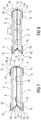
- the operating devices shown in the figures have a first flat component 2 facing an operator 1 a ferromagnetic material that is movable transversely to its surface extension.
- a second flat component 3 made of a ferromagnetic material is arranged immovably.
- the second flat component 3 has coil cores 4 at a distance from one another, which are directed towards the first flat component 2 and are formed in one piece with the second flat component 3 (in the Figures 9-13 not shown).
- the coil cores 4 are each enclosed by a pair of spiral-like flat coils 5, 5 '.
- the flat coils 5, 5 ' are printed on a printed circuit board 6 that extends over the surface of the flat components 2, 3 and is designed as a ceramic substrate, with the flat coils 5 on the first flat component 2 and the flat coils 5' on the second flat component 3 facing side are printed on the circuit board 6.
- the coil cores 4 protrude through recesses 7 correspondingly formed in the circuit board 6.
- the printed circuit board 6 carrying the flat coils 5, 5 ′ is glued onto the surface of the second flat component 3 facing the first flat component 2.
- the circuit board 6 could, however, also be connected to the second flat component 3 by a screw connection.
- first flat component 2 and the second flat component 3 are of the same at their mutually opposite edge regions, as Stamped and bent part formed from a spring plate connecting elements 9 encompassed, which in their in Figure 1
- the relaxed position shown have a connection area 11 perpendicular to the plane of the flat components 2, 3 and fastening ends 10 directed at right angles to the connection areas 11 at both ends.
- the fastening ends 10 are fastened to the surfaces of the first and second flat components 2 and 3 that are remote from one another.
- the resilient areas 12 are in the Figure 1 shown rest position without or without substantial spring tension. If the fastening ends 10 are deflected by the application of force from their orientation perpendicular to the connection area 11 ( Figure 2 ), a spring tension builds up in the resilient areas 12 which, after the application of force has ended, moves the connecting elements 9 and the first flat component 2 firmly connected to them back into the rest position.
- the connecting areas 14 between the resilient areas 12 have stiffeners 13 bent at right angles out of the plane of the spring surface, so that the connecting areas 11 are rigid.
- first and the second flat component 2 and 3 are connected to one another at their opposite ends by two identical connecting elements 9 'formed as stamped and bent parts from a spring plate.
- connection area 11 'to the fastening ends 10 form in the Figures 3 and 4 like in the Figures 1 and 2 Resilient areas 12, which in the Figure 3 and 5 are at least largely de-energized.
- FIGS. 6a to 6d show connecting elements 9 'in the rest position with different inclinations.
- FIGS 7 and 8 are the first and the second flat component 2 and 3 by two connecting elements formed as stamped and bent parts from a spring steel sheet 9 '', 9 '''connected to one another at their opposite ends.
- the connecting elements 9 ′′, 9 ′′ ′′ have fastening ends 10 with which they are fastened to the surfaces of the flat components 2 and 3 facing away from one another.
- each of the connecting elements 9 ′′, 9 ′′ ′′ are connected to one another via two connecting partial areas 14 having stiffeners 13.
- each connecting element 9 ′′, 9 ′′ ′′ stand in a V-shape to one another and are connected at their ends that are remote from one another to a respective fastening end 10 via resilient regions 12.
- the connecting elements 14 are connected to one another via a further resilient region 15.
- the “V” of the connecting elements 9 ′′, 9 ′′ ′′ are directed in the same direction parallel to the flat components 2 and 3 and are connected to one another at their further resilient areas 15 by a rigid coupling element 16.
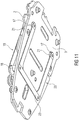
- the first planar component 2 has a first connecting piece 18, on whose end directed towards the operator 1 the first fastening end 10 of a first connecting element 19 and on whose end protruding away from the operator 1 the first fastening end 10 of a second connecting element 20 is fastened.
- the second flat component 3 has a second connection piece 21, to whose end protruding away from the operator 1 the second fastening end 10 of the second connecting element 20 and to whose end facing the operator 1 the second fastening end 10 of the first connecting element 19 is fastened.
- the connecting elements 19 and 20 have connecting regions 11, fastening ends 10, stiffeners 13 and resilient regions 12.
- the end of the first connection piece 18 protruding away from the operator 1 protrudes with play through an opening 17 of the second flat component 3 and the end of the second connection piece 21 protruding towards the operator 1 protrudes with play through an opening 17 of the first flat component 2.
- the first and second connecting pieces 18 and 21 as well as the first and second connecting elements 19 and 20 form a first connecting unit 22.
- An identical connecting unit 22 ′ is arranged parallel to the first connecting unit 22, the two connecting units being connected to one another by three rigid transverse webs 23.
- a sensor system (not shown) detects that a finger of the operator 1 is touching the first flat component 2, the flat coils 5, 5 ′ are energized.
- the first flat component 2 simultaneously forms an operating element so that the operator senses the movement of the first flat component 2 haptically.
Landscapes
- Engineering & Computer Science (AREA)
- General Engineering & Computer Science (AREA)
- Physics & Mathematics (AREA)
- General Physics & Mathematics (AREA)
- Theoretical Computer Science (AREA)
- Automation & Control Theory (AREA)
- Human Computer Interaction (AREA)
- Manufacturing & Machinery (AREA)
- User Interface Of Digital Computer (AREA)
- Reciprocating, Oscillating Or Vibrating Motors (AREA)
- Apparatuses For Generation Of Mechanical Vibrations (AREA)
- Push-Button Switches (AREA)
Claims (13)
- Dispositif de commande comprenant un élément de commande à rétroaction haptique, dans lequel l'élément de commande peut être actionné par un opérateur (1) au moyen d'un organe d'entrée, comportant des premier et deuxième éléments plans qui sont orientés de manière à ce que leurs grandes surfaces soient parallèles l'une à l'autre et qui sont mobiles l'un par rapport à l'autre, dans lequel le premier élément plan forme l'élément de commande ou transmet son mouvement en totalité ou en partie à l'élément de commande, dans lequel les éléments plans (2, 3) sont guidés, tout en conservant leur parallélisme l'un par rapport à l'autre, entre une position de repos et une position d'actionnement, dans lequel la distance entre les deux éléments plans (2, 3) dans la position d'actionnement est moindre que dans la position de repos et les deux éléments plans (2, 3) sont sollicités par ressort dans leur position de repos, et dans lequel les éléments plans (2, 3) peuvent être entraînés par un actionneur de manière à pouvoir être déplacés contre la force de ressort de leur position de repos vers leur position d'actionnement, dans lequel les éléments plans (2, 3) sont en totalité ou en partie constitués d'un matériau ferromagnétique, caractérisé en ce qu'au moins une bobine est disposée entre les éléments plans (2, 3), dans lequel les éléments plans (2, 3) peuvent être déplacés par alimentation en courant de la bobine, en se déplaçant les uns par rapport aux autres dans leurs plans et en réduisant leur distance les uns par rapport aux autres, et en ce que la bobine est une bobine plane (5, 5') disposée sur une carte de circuit imprimé (6).
- Dispositif de commande selon l'une des revendications précédentes, caractérisé en ce que le premier élément plan (2) et le deuxième élément plan (3) sont reliés l'un à l'autre par deux liaisons qui sont respectivement fixées à la même distance et dans la même direction dans le prolongement des plans des éléments plans (2, 3) de manière à ce que leur première extrémité de fixation (10) soit directement ou indirectement fixée au premier élément plan (2) et à ce que leur autre extrémité de fixation (10) soit directement ou indirectement fixée au deuxième élément plan (3), qui s'étendent entre leurs extrémités de fixation (10) et parallèlement les unes aux autres et présentent des zones élastiques (12) à proximité des extrémités de fixation (10) et qui sont conçues pour être rigides en flexion dans leur zone de liaison (11, 11') entre les extrémités de fixation (10), dans lequel les zones élastiques (12) exercent sur les éléments plans (2, 3) une précontrainte qui les éloigne les unes des autres.
- Dispositif de commande selon la revendication 2, caractérisé en ce que le premier élément plan (2) présente, en tant que liaison, une première pièce de liaison (18) à l'extrémité, dirigée vers l'opérateur (1), de laquelle est fixée la première extrémité de fixation (10) d'un premier élément de liaison (19) et à l'extrémité, s'écartant de l'opérateur (1), de laquelle est fixée la première extrémité de fixation (10) d'un deuxième élément de liaison (20), et en ce que le deuxième élément plan (3) présente, en tant que liaison, une deuxième pièce de liaison (21), à l'extrémité, s'écartant de l'opérateur (1), de laquelle est fixée la deuxième extrémité de fixation (10) du deuxième élément de liaison (20) et à l'extrémité, dirigée vers l'opérateur (1), de laquelle est fixée la deuxième extrémité de fixation (10) du premier élément de liaison (19).
- Dispositif de commande selon la revendication 3, caractérisé en ce que l'extrémité du premier élément de liaison (18) s'écartant de l'opérateur (1) fait saillie avec jeu à travers une ouverture (17) du deuxième élément plan (3) et l'extrémité du deuxième élément de liaison (21) se rapprochant de l'opérateur (1) fait saillie avec jeu à travers une ouverture (17) du premier élément plan (2).
- Dispositif de commande selon l'une des revendications 3 et 4, caractérisé en ce qu'une deuxième unité de liaison identique (22') est disposée parallèlement à une unité de liaison (22) constituée d'une première et d'une deuxième pièce de liaison (18, 21) et d'un premier et d'un deuxième élément de liaison (19, 20), dans lequel les premiers éléments de liaison (19) et/ou les deuxièmes éléments de liaison (20) des deux unités de liaison (22, 22') sont reliés l'un à l'autre par une ou plusieurs barres transversales rigides (23).
- Dispositif de commande selon la revendication 2, caractérisé en ce que les zones de liaison (11') s'étendent avec une plus grande inclinaison par rapport au plan des éléments plans (2, 3) lorsque la bobine plane n'est pas alimentée en courant que lorsque la bobine plane est alimentée en courant.
- Dispositif de commande selon la revendication 2, caractérisé en ce que les zones de liaison sont constituées de deux zones de liaison (14) rigides en flexion, qui sont reliées l'une à l'autre par une autre zone élastique (15) et qui s'étendent par rapport au plan des éléments plans (2, 3) sous des angles dont la somme est un angle complémentaire par rapport au plan des éléments plans (2, 3) et qui sont reliées l'une à l'autre par un élément de couplage (16) s'étendant parallèlement au plan des éléments plans (2, 3).
- Dispositif de commande selon l'une des revendications précédentes, caractérisé en ce que les éléments de liaison (9, 9', 9'', 9''') sont réalisés sous la forme d'une pièce de tôle découpée et pliée.
- Dispositif de commande selon la revendication 8, caractérisé en ce que les éléments de liaison (9, 9', 9'', 9''') sont pliés hors du plan de la tôle dans la zone de liaison (11, 11') ou dans les zones partielles de liaison (14) le long des bords longitudinaux entre les zones élastiques (12) ou entre les zones élastiques (12) et l'autre zone élastique (15).
- Dispositif de commande selon la revendication 8, caractérisé en ce que les éléments de liaison présentent, dans la zone de liaison ou dans les zones partielles de liaison, une ou plusieurs encoches s'étendant le long de leur extension longitudinale entre les zones élastiques.
- Dispositif de commande selon l'une des revendications précédentes, caractérisé en ce que la carte de circuit imprimé (6) portant la bobine plane (5, 5') est disposée de manière fixe sur la surface du deuxième élément plan (3) qui est tournée vers le premier élément plan (2).
- Dispositif de commande selon la revendication 11, caractérisé en ce que la carte de circuit imprimé (6) est disposée sur le deuxième élément plan (3) au moyen d'une couche adhésive (8) ou est appliquée sur le deuxième élément plan par une technique de stratification.
- Dispositif de commande selon l'une des revendications précédentes, caractérisé en ce que l'élément de commande est réalisé sous la forme d'un afficheur.
Applications Claiming Priority (2)
| Application Number | Priority Date | Filing Date | Title |
|---|---|---|---|
| DE102011082143A DE102011082143A1 (de) | 2011-09-05 | 2011-09-05 | Bedieneinrichtung |
| PCT/EP2012/066861 WO2013034483A1 (fr) | 2011-09-05 | 2012-08-30 | Dispositif de commande |
Publications (2)
| Publication Number | Publication Date |
|---|---|
| EP2754006A1 EP2754006A1 (fr) | 2014-07-16 |
| EP2754006B1 true EP2754006B1 (fr) | 2020-11-25 |
Family
ID=46851428
Family Applications (1)
| Application Number | Title | Priority Date | Filing Date |
|---|---|---|---|
| EP12759056.0A Active EP2754006B1 (fr) | 2011-09-05 | 2012-08-30 | Dispositif de commande |
Country Status (4)
| Country | Link |
|---|---|
| US (1) | US9746847B2 (fr) |
| EP (1) | EP2754006B1 (fr) |
| DE (1) | DE102011082143A1 (fr) |
| WO (1) | WO2013034483A1 (fr) |
Families Citing this family (6)
| Publication number | Priority date | Publication date | Assignee | Title |
|---|---|---|---|---|
| EP3172641B1 (fr) | 2014-07-22 | 2020-04-08 | Behr-Hella Thermocontrol GmbH | Unité de commande d'appareil électrique |
| ES2819872T3 (es) * | 2015-10-23 | 2021-04-19 | Behr Hella Thermocontrol Gmbh | Unidad de mando para un componente de vehículo, en particular para una instalación de calefacción, de ventilación y/o de climatización |
| DE102015222714A1 (de) | 2015-11-18 | 2017-05-18 | Robert Bosch Gmbh | Bedienvorrichtung |
| EP3608747B1 (fr) * | 2018-08-06 | 2022-09-14 | Robert Bosch GmbH | Dispositif de commande pour un véhicule, véhicule |
| DE102022100993B4 (de) | 2022-01-17 | 2023-10-26 | Behr-Hella Thermocontrol Gmbh | Bedieneinheit für ein Fahrzeug, insbesondere für eine oder mehrere Fahrzeugkomponenten |
| DE102022101657A1 (de) * | 2022-01-25 | 2023-07-27 | Valeo Schalter Und Sensoren Gmbh | Eingabevorrichtung für ein Kraftfahrzeug |
Family Cites Families (21)
| Publication number | Priority date | Publication date | Assignee | Title |
|---|---|---|---|---|
| KR19980032013A (ko) * | 1995-12-15 | 1998-07-25 | 모리시타요오이찌 | 진동 발생장치 |
| JP3949912B2 (ja) * | 2000-08-08 | 2007-07-25 | 株式会社エヌ・ティ・ティ・ドコモ | 携帯型電子機器、電子機器、振動発生器、振動による報知方法および報知制御方法 |
| JP2003154315A (ja) * | 2001-11-22 | 2003-05-27 | Matsushita Electric Ind Co Ltd | 振動リニアアクチュエータ |
| JP4500485B2 (ja) * | 2002-08-28 | 2010-07-14 | 株式会社日立製作所 | タッチパネルを備えた表示装置 |
| KR100549880B1 (ko) * | 2003-07-05 | 2006-02-06 | 엘지이노텍 주식회사 | 진동장치 구조 |
| KR100735299B1 (ko) * | 2004-06-23 | 2007-07-03 | 삼성전기주식회사 | 수직진동자 |
| FR2875024B1 (fr) * | 2004-09-09 | 2007-06-08 | Itt Mfg Enterprises Inc | Dalle tactile comportant des moyens pour produire une impulsion mecanique en reponse a une action de commande, et agencement pour le montage de cette dalle |
| JP4860625B2 (ja) * | 2004-10-08 | 2012-01-25 | イマージョン コーポレーション | タッチ式入力装置におけるボタンおよびスクロール動作シミュレーション用の触覚フィードバック |
| US7825903B2 (en) * | 2005-05-12 | 2010-11-02 | Immersion Corporation | Method and apparatus for providing haptic effects to a touch panel |
| DE102005054677A1 (de) * | 2005-11-16 | 2007-06-06 | Siemens Ag | Berührungsempfindliche Bedieneinheit mit haptischer Rückmeldung |
| GB2446702A (en) * | 2007-02-13 | 2008-08-20 | Qrg Ltd | Touch Control Panel with Pressure Sensor |
| US9056549B2 (en) * | 2008-03-28 | 2015-06-16 | Denso International America, Inc. | Haptic tracking remote control for driver information center system |
| JP5033078B2 (ja) * | 2008-08-06 | 2012-09-26 | 株式会社ジャパンディスプレイイースト | 表示装置 |
| DE102008058568A1 (de) * | 2008-11-21 | 2010-05-27 | Continental Automotive Gmbh | Haptische Bedieneinrichtung |
| US9684375B2 (en) * | 2008-12-12 | 2017-06-20 | Immersion Corporation | Systems and methods for stabilizing a haptic touch panel or touch surface |
| US8760413B2 (en) * | 2009-01-08 | 2014-06-24 | Synaptics Incorporated | Tactile surface |
| DE102009036860A1 (de) * | 2009-08-10 | 2011-03-03 | Siemens Aktiengesellschaft | Bedieneinheit, Gerät und Verfahren |
| DE102010007486A1 (de) * | 2010-02-09 | 2011-08-11 | Continental Automotive GmbH, 30165 | Bedienvorrichtung |
| KR101122797B1 (ko) * | 2010-04-26 | 2012-03-21 | 엘지이노텍 주식회사 | 광대역폭을 가진 선형 진동기 |
| US20110291947A1 (en) * | 2010-05-27 | 2011-12-01 | Nigel Patrick Pemberton-Pigott | Touch-Sensitive Display |
| KR101080641B1 (ko) * | 2010-06-30 | 2011-11-08 | 주식회사 하이소닉 | 햅틱모듈이 구비된 휴대단말기 |
-
2011
- 2011-09-05 DE DE102011082143A patent/DE102011082143A1/de not_active Withdrawn
-
2012
- 2012-08-30 US US14/342,982 patent/US9746847B2/en active Active
- 2012-08-30 WO PCT/EP2012/066861 patent/WO2013034483A1/fr active Application Filing
- 2012-08-30 EP EP12759056.0A patent/EP2754006B1/fr active Active
Non-Patent Citations (1)
| Title |
|---|
| None * |
Also Published As
| Publication number | Publication date |
|---|---|
| WO2013034483A1 (fr) | 2013-03-14 |
| US9746847B2 (en) | 2017-08-29 |
| DE102011082143A1 (de) | 2013-03-07 |
| US20140207268A1 (en) | 2014-07-24 |
| EP2754006A1 (fr) | 2014-07-16 |
Similar Documents
| Publication | Publication Date | Title |
|---|---|---|
| EP2754006B1 (fr) | Dispositif de commande | |
| EP2534555B1 (fr) | Dispositif de commande | |
| EP2734910B1 (fr) | Système de commande | |
| EP2920665B1 (fr) | Dispositif de commande pour un appareil de véhicule | |
| EP2745187B1 (fr) | Dispositif de commande | |
| DE102011079711B4 (de) | Bedienvorrichtung | |
| EP3350013B1 (fr) | Unité de commande pour un véhicule | |
| EP2197115B1 (fr) | Dispositif de commande doté d'au moins un interrupteur à pression | |
| DE102010041345A1 (de) | Vorrichtung zur Befestigung für eine haptische Oberfläche | |
| DE102007054778A1 (de) | Bedienvorrichtung mit wenigstens einem Druckschalter | |
| EP3774433B1 (fr) | Dispositif de commande pour un véhicule | |
| EP3455868B1 (fr) | Actionneur de rétroaction électromagnétique pour élément de commande et dispositif équipé d'au moins un actionneur de rétroaction électromagnétique | |
| EP3593228B1 (fr) | Actionneur électromagnétique d'un dispositif de retour tactile | |
| DE102007058110B4 (de) | Schalter | |
| DE2214105B2 (de) | Momentschalter mit einem schaltglied und einer entgegen einer federkraft herabdrueckbaren betaetigungstaste | |
| EP2920553B1 (fr) | Capteur capacitif permettant de détecter un mouvement relatif de deux corps adjacents | |
| DE102012219474A1 (de) | Drucktastenanordnung mit einer Parallelschwinge | |
| EP2071276B1 (fr) | Capteur | |
| DE102011082142A1 (de) | Bedieneinrichtung | |
| DE102009025458B4 (de) | Sensor | |
| WO2019048681A1 (fr) | Dispositif de commande comportant une poignée à retour haptique pouvant basculer dans plusieurs directions |
Legal Events
| Date | Code | Title | Description |
|---|---|---|---|
| PUAI | Public reference made under article 153(3) epc to a published international application that has entered the european phase |
Free format text: ORIGINAL CODE: 0009012 |
|
| 17P | Request for examination filed |
Effective date: 20140407 |
|
| AK | Designated contracting states |
Kind code of ref document: A1 Designated state(s): AL AT BE BG CH CY CZ DE DK EE ES FI FR GB GR HR HU IE IS IT LI LT LU LV MC MK MT NL NO PL PT RO RS SE SI SK SM TR |
|
| RIN1 | Information on inventor provided before grant (corrected) |
Inventor name: GUTERMUTH, UWE Inventor name: VORBERG, SABINE Inventor name: KISSEL, ROBERT, WOLFGANG Inventor name: KERN, THORSTEN, ALEXANDER Inventor name: ZOLLER, INGO |
|
| DAX | Request for extension of the european patent (deleted) | ||
| STAA | Information on the status of an ep patent application or granted ep patent |
Free format text: STATUS: EXAMINATION IS IN PROGRESS |
|
| 17Q | First examination report despatched |
Effective date: 20181207 |
|
| RIC1 | Information provided on ipc code assigned before grant |
Ipc: G05G 5/03 20080401ALI20130327BHEP Ipc: G06F 3/01 20060101AFI20130327BHEP |
|
| GRAP | Despatch of communication of intention to grant a patent |
Free format text: ORIGINAL CODE: EPIDOSNIGR1 |
|
| STAA | Information on the status of an ep patent application or granted ep patent |
Free format text: STATUS: GRANT OF PATENT IS INTENDED |
|
| INTG | Intention to grant announced |
Effective date: 20200623 |
|
| RAP1 | Party data changed (applicant data changed or rights of an application transferred) |
Owner name: CONTINENTAL AUTOMOTIVE GMBH |
|
| GRAS | Grant fee paid |
Free format text: ORIGINAL CODE: EPIDOSNIGR3 |
|
| GRAA | (expected) grant |
Free format text: ORIGINAL CODE: 0009210 |
|
| STAA | Information on the status of an ep patent application or granted ep patent |
Free format text: STATUS: THE PATENT HAS BEEN GRANTED |
|
| AK | Designated contracting states |
Kind code of ref document: B1 Designated state(s): AL AT BE BG CH CY CZ DE DK EE ES FI FR GB GR HR HU IE IS IT LI LT LU LV MC MK MT NL NO PL PT RO RS SE SI SK SM TR |
|
| REG | Reference to a national code |
Ref country code: GB Ref legal event code: FG4D Free format text: NOT ENGLISH |
|
| REG | Reference to a national code |
Ref country code: CH Ref legal event code: EP |
|
| REG | Reference to a national code |
Ref country code: DE Ref legal event code: R096 Ref document number: 502012016501 Country of ref document: DE |
|
| REG | Reference to a national code |
Ref country code: AT Ref legal event code: REF Ref document number: 1339047 Country of ref document: AT Kind code of ref document: T Effective date: 20201215 |
|
| REG | Reference to a national code |
Ref country code: IE Ref legal event code: FG4D Free format text: LANGUAGE OF EP DOCUMENT: GERMAN |
|
| REG | Reference to a national code |
Ref country code: NL Ref legal event code: MP Effective date: 20201125 |
|
| PG25 | Lapsed in a contracting state [announced via postgrant information from national office to epo] |
Ref country code: NO Free format text: LAPSE BECAUSE OF FAILURE TO SUBMIT A TRANSLATION OF THE DESCRIPTION OR TO PAY THE FEE WITHIN THE PRESCRIBED TIME-LIMIT Effective date: 20210225 Ref country code: PT Free format text: LAPSE BECAUSE OF FAILURE TO SUBMIT A TRANSLATION OF THE DESCRIPTION OR TO PAY THE FEE WITHIN THE PRESCRIBED TIME-LIMIT Effective date: 20210325 Ref country code: FI Free format text: LAPSE BECAUSE OF FAILURE TO SUBMIT A TRANSLATION OF THE DESCRIPTION OR TO PAY THE FEE WITHIN THE PRESCRIBED TIME-LIMIT Effective date: 20201125 Ref country code: RS Free format text: LAPSE BECAUSE OF FAILURE TO SUBMIT A TRANSLATION OF THE DESCRIPTION OR TO PAY THE FEE WITHIN THE PRESCRIBED TIME-LIMIT Effective date: 20201125 Ref country code: GR Free format text: LAPSE BECAUSE OF FAILURE TO SUBMIT A TRANSLATION OF THE DESCRIPTION OR TO PAY THE FEE WITHIN THE PRESCRIBED TIME-LIMIT Effective date: 20210226 |
|
| PG25 | Lapsed in a contracting state [announced via postgrant information from national office to epo] |
Ref country code: BG Free format text: LAPSE BECAUSE OF FAILURE TO SUBMIT A TRANSLATION OF THE DESCRIPTION OR TO PAY THE FEE WITHIN THE PRESCRIBED TIME-LIMIT Effective date: 20210225 Ref country code: PL Free format text: LAPSE BECAUSE OF FAILURE TO SUBMIT A TRANSLATION OF THE DESCRIPTION OR TO PAY THE FEE WITHIN THE PRESCRIBED TIME-LIMIT Effective date: 20201125 Ref country code: IS Free format text: LAPSE BECAUSE OF FAILURE TO SUBMIT A TRANSLATION OF THE DESCRIPTION OR TO PAY THE FEE WITHIN THE PRESCRIBED TIME-LIMIT Effective date: 20210325 Ref country code: LV Free format text: LAPSE BECAUSE OF FAILURE TO SUBMIT A TRANSLATION OF THE DESCRIPTION OR TO PAY THE FEE WITHIN THE PRESCRIBED TIME-LIMIT Effective date: 20201125 Ref country code: SE Free format text: LAPSE BECAUSE OF FAILURE TO SUBMIT A TRANSLATION OF THE DESCRIPTION OR TO PAY THE FEE WITHIN THE PRESCRIBED TIME-LIMIT Effective date: 20201125 |
|
| REG | Reference to a national code |
Ref country code: LT Ref legal event code: MG9D |
|
| PG25 | Lapsed in a contracting state [announced via postgrant information from national office to epo] |
Ref country code: HR Free format text: LAPSE BECAUSE OF FAILURE TO SUBMIT A TRANSLATION OF THE DESCRIPTION OR TO PAY THE FEE WITHIN THE PRESCRIBED TIME-LIMIT Effective date: 20201125 |
|
| PG25 | Lapsed in a contracting state [announced via postgrant information from national office to epo] |
Ref country code: CZ Free format text: LAPSE BECAUSE OF FAILURE TO SUBMIT A TRANSLATION OF THE DESCRIPTION OR TO PAY THE FEE WITHIN THE PRESCRIBED TIME-LIMIT Effective date: 20201125 Ref country code: EE Free format text: LAPSE BECAUSE OF FAILURE TO SUBMIT A TRANSLATION OF THE DESCRIPTION OR TO PAY THE FEE WITHIN THE PRESCRIBED TIME-LIMIT Effective date: 20201125 Ref country code: SM Free format text: LAPSE BECAUSE OF FAILURE TO SUBMIT A TRANSLATION OF THE DESCRIPTION OR TO PAY THE FEE WITHIN THE PRESCRIBED TIME-LIMIT Effective date: 20201125 Ref country code: RO Free format text: LAPSE BECAUSE OF FAILURE TO SUBMIT A TRANSLATION OF THE DESCRIPTION OR TO PAY THE FEE WITHIN THE PRESCRIBED TIME-LIMIT Effective date: 20201125 Ref country code: SK Free format text: LAPSE BECAUSE OF FAILURE TO SUBMIT A TRANSLATION OF THE DESCRIPTION OR TO PAY THE FEE WITHIN THE PRESCRIBED TIME-LIMIT Effective date: 20201125 Ref country code: LT Free format text: LAPSE BECAUSE OF FAILURE TO SUBMIT A TRANSLATION OF THE DESCRIPTION OR TO PAY THE FEE WITHIN THE PRESCRIBED TIME-LIMIT Effective date: 20201125 |
|
| REG | Reference to a national code |
Ref country code: DE Ref legal event code: R097 Ref document number: 502012016501 Country of ref document: DE |
|
| PG25 | Lapsed in a contracting state [announced via postgrant information from national office to epo] |
Ref country code: DK Free format text: LAPSE BECAUSE OF FAILURE TO SUBMIT A TRANSLATION OF THE DESCRIPTION OR TO PAY THE FEE WITHIN THE PRESCRIBED TIME-LIMIT Effective date: 20201125 |
|
| PLBE | No opposition filed within time limit |
Free format text: ORIGINAL CODE: 0009261 |
|
| STAA | Information on the status of an ep patent application or granted ep patent |
Free format text: STATUS: NO OPPOSITION FILED WITHIN TIME LIMIT |
|
| PG25 | Lapsed in a contracting state [announced via postgrant information from national office to epo] |
Ref country code: IT Free format text: LAPSE BECAUSE OF FAILURE TO SUBMIT A TRANSLATION OF THE DESCRIPTION OR TO PAY THE FEE WITHIN THE PRESCRIBED TIME-LIMIT Effective date: 20201125 Ref country code: AL Free format text: LAPSE BECAUSE OF FAILURE TO SUBMIT A TRANSLATION OF THE DESCRIPTION OR TO PAY THE FEE WITHIN THE PRESCRIBED TIME-LIMIT Effective date: 20201125 Ref country code: NL Free format text: LAPSE BECAUSE OF FAILURE TO SUBMIT A TRANSLATION OF THE DESCRIPTION OR TO PAY THE FEE WITHIN THE PRESCRIBED TIME-LIMIT Effective date: 20201125 |
|
| PGFP | Annual fee paid to national office [announced via postgrant information from national office to epo] |
Ref country code: FR Payment date: 20210819 Year of fee payment: 10 |
|
| 26N | No opposition filed |
Effective date: 20210826 |
|
| PG25 | Lapsed in a contracting state [announced via postgrant information from national office to epo] |
Ref country code: ES Free format text: LAPSE BECAUSE OF FAILURE TO SUBMIT A TRANSLATION OF THE DESCRIPTION OR TO PAY THE FEE WITHIN THE PRESCRIBED TIME-LIMIT Effective date: 20201125 Ref country code: SI Free format text: LAPSE BECAUSE OF FAILURE TO SUBMIT A TRANSLATION OF THE DESCRIPTION OR TO PAY THE FEE WITHIN THE PRESCRIBED TIME-LIMIT Effective date: 20201125 |
|
| REG | Reference to a national code |
Ref country code: CH Ref legal event code: PL |
|
| PG25 | Lapsed in a contracting state [announced via postgrant information from national office to epo] |
Ref country code: MC Free format text: LAPSE BECAUSE OF FAILURE TO SUBMIT A TRANSLATION OF THE DESCRIPTION OR TO PAY THE FEE WITHIN THE PRESCRIBED TIME-LIMIT Effective date: 20201125 |
|
| REG | Reference to a national code |
Ref country code: BE Ref legal event code: MM Effective date: 20210831 |
|
| GBPC | Gb: european patent ceased through non-payment of renewal fee |
Effective date: 20210830 |
|
| PG25 | Lapsed in a contracting state [announced via postgrant information from national office to epo] |
Ref country code: LI Free format text: LAPSE BECAUSE OF NON-PAYMENT OF DUE FEES Effective date: 20210831 Ref country code: CH Free format text: LAPSE BECAUSE OF NON-PAYMENT OF DUE FEES Effective date: 20210831 |
|
| PG25 | Lapsed in a contracting state [announced via postgrant information from national office to epo] |
Ref country code: IS Free format text: LAPSE BECAUSE OF FAILURE TO SUBMIT A TRANSLATION OF THE DESCRIPTION OR TO PAY THE FEE WITHIN THE PRESCRIBED TIME-LIMIT Effective date: 20210325 Ref country code: LU Free format text: LAPSE BECAUSE OF NON-PAYMENT OF DUE FEES Effective date: 20210830 |
|
| REG | Reference to a national code |
Ref country code: DE Ref legal event code: R081 Ref document number: 502012016501 Country of ref document: DE Owner name: CONTINENTAL AUTOMOTIVE TECHNOLOGIES GMBH, DE Free format text: FORMER OWNER: CONTINENTAL AUTOMOTIVE GMBH, 30165 HANNOVER, DE |
|
| PG25 | Lapsed in a contracting state [announced via postgrant information from national office to epo] |
Ref country code: IE Free format text: LAPSE BECAUSE OF NON-PAYMENT OF DUE FEES Effective date: 20210830 Ref country code: GB Free format text: LAPSE BECAUSE OF NON-PAYMENT OF DUE FEES Effective date: 20210830 Ref country code: BE Free format text: LAPSE BECAUSE OF NON-PAYMENT OF DUE FEES Effective date: 20210831 |
|
| REG | Reference to a national code |
Ref country code: AT Ref legal event code: MM01 Ref document number: 1339047 Country of ref document: AT Kind code of ref document: T Effective date: 20210830 |
|
| PG25 | Lapsed in a contracting state [announced via postgrant information from national office to epo] |
Ref country code: AT Free format text: LAPSE BECAUSE OF NON-PAYMENT OF DUE FEES Effective date: 20210830 |
|
| PG25 | Lapsed in a contracting state [announced via postgrant information from national office to epo] |
Ref country code: HU Free format text: LAPSE BECAUSE OF FAILURE TO SUBMIT A TRANSLATION OF THE DESCRIPTION OR TO PAY THE FEE WITHIN THE PRESCRIBED TIME-LIMIT; INVALID AB INITIO Effective date: 20120830 Ref country code: CY Free format text: LAPSE BECAUSE OF FAILURE TO SUBMIT A TRANSLATION OF THE DESCRIPTION OR TO PAY THE FEE WITHIN THE PRESCRIBED TIME-LIMIT Effective date: 20201125 |
|
| P01 | Opt-out of the competence of the unified patent court (upc) registered |
Effective date: 20230522 |
|
| PG25 | Lapsed in a contracting state [announced via postgrant information from national office to epo] |
Ref country code: FR Free format text: LAPSE BECAUSE OF NON-PAYMENT OF DUE FEES Effective date: 20220831 |
|
| PGFP | Annual fee paid to national office [announced via postgrant information from national office to epo] |
Ref country code: DE Payment date: 20230831 Year of fee payment: 12 |
|
| REG | Reference to a national code |
Ref country code: DE Ref legal event code: R081 Ref document number: 502012016501 Country of ref document: DE Owner name: CONTINENTAL AUTOMOTIVE TECHNOLOGIES GMBH, DE Free format text: FORMER OWNER: CONTINENTAL AUTOMOTIVE TECHNOLOGIES GMBH, 30165 HANNOVER, DE |
|
| PG25 | Lapsed in a contracting state [announced via postgrant information from national office to epo] |
Ref country code: MK Free format text: LAPSE BECAUSE OF FAILURE TO SUBMIT A TRANSLATION OF THE DESCRIPTION OR TO PAY THE FEE WITHIN THE PRESCRIBED TIME-LIMIT Effective date: 20201125 |
|
| PG25 | Lapsed in a contracting state [announced via postgrant information from national office to epo] |
Ref country code: TR Free format text: LAPSE BECAUSE OF FAILURE TO SUBMIT A TRANSLATION OF THE DESCRIPTION OR TO PAY THE FEE WITHIN THE PRESCRIBED TIME-LIMIT Effective date: 20201125 |