EP2754006B1 - Operating arrangement - Google Patents
Operating arrangement Download PDFInfo
- Publication number
- EP2754006B1 EP2754006B1 EP12759056.0A EP12759056A EP2754006B1 EP 2754006 B1 EP2754006 B1 EP 2754006B1 EP 12759056 A EP12759056 A EP 12759056A EP 2754006 B1 EP2754006 B1 EP 2754006B1
- Authority
- EP
- European Patent Office
- Prior art keywords
- planar
- operator control
- operator
- control device
- components
- Prior art date
- Legal status (The legal status is an assumption and is not a legal conclusion. Google has not performed a legal analysis and makes no representation as to the accuracy of the status listed.)
- Active
Links
- 239000012790 adhesive layer Substances 0.000 claims description 4
- 239000003302 ferromagnetic material Substances 0.000 claims description 4
- 229910052751 metal Inorganic materials 0.000 claims description 4
- 239000002184 metal Substances 0.000 claims description 4
- 230000008878 coupling Effects 0.000 claims description 3
- 238000010168 coupling process Methods 0.000 claims description 3
- 238000005859 coupling reaction Methods 0.000 claims description 3
- 238000006073 displacement reaction Methods 0.000 claims description 3
- 238000005516 engineering process Methods 0.000 claims description 3
- 230000000295 complement effect Effects 0.000 claims description 2
- 230000004913 activation Effects 0.000 claims 3
- 230000005294 ferromagnetic effect Effects 0.000 description 5
- 238000009434 installation Methods 0.000 description 5
- 230000005291 magnetic effect Effects 0.000 description 5
- 239000004020 conductor Substances 0.000 description 4
- 239000003351 stiffener Substances 0.000 description 4
- 230000004907 flux Effects 0.000 description 3
- 229910000639 Spring steel Inorganic materials 0.000 description 2
- 239000010410 layer Substances 0.000 description 2
- 238000007639 printing Methods 0.000 description 2
- 230000007704 transition Effects 0.000 description 2
- BQCADISMDOOEFD-UHFFFAOYSA-N Silver Chemical compound [Ag] BQCADISMDOOEFD-UHFFFAOYSA-N 0.000 description 1
- 238000005452 bending Methods 0.000 description 1
- 239000000919 ceramic Substances 0.000 description 1
- 239000012141 concentrate Substances 0.000 description 1
- 230000001419 dependent effect Effects 0.000 description 1
- 230000000694 effects Effects 0.000 description 1
- 238000004049 embossing Methods 0.000 description 1
- 238000005530 etching Methods 0.000 description 1
- 238000009413 insulation Methods 0.000 description 1
- 239000004973 liquid crystal related substance Substances 0.000 description 1
- 238000004519 manufacturing process Methods 0.000 description 1
- 239000000463 material Substances 0.000 description 1
- 239000011159 matrix material Substances 0.000 description 1
- 238000000034 method Methods 0.000 description 1
- 230000005693 optoelectronics Effects 0.000 description 1
- 210000000056 organ Anatomy 0.000 description 1
- 230000008569 process Effects 0.000 description 1
- 230000009467 reduction Effects 0.000 description 1
- 229910052709 silver Inorganic materials 0.000 description 1
- 239000004332 silver Substances 0.000 description 1
- 239000000758 substrate Substances 0.000 description 1
Images


Classifications
-
- G—PHYSICS
- G05—CONTROLLING; REGULATING
- G05B—CONTROL OR REGULATING SYSTEMS IN GENERAL; FUNCTIONAL ELEMENTS OF SUCH SYSTEMS; MONITORING OR TESTING ARRANGEMENTS FOR SUCH SYSTEMS OR ELEMENTS
- G05B19/00—Programme-control systems
- G05B19/02—Programme-control systems electric
- G05B19/18—Numerical control [NC], i.e. automatically operating machines, in particular machine tools, e.g. in a manufacturing environment, so as to execute positioning, movement or co-ordinated operations by means of programme data in numerical form
- G05B19/402—Numerical control [NC], i.e. automatically operating machines, in particular machine tools, e.g. in a manufacturing environment, so as to execute positioning, movement or co-ordinated operations by means of programme data in numerical form characterised by control arrangements for positioning, e.g. centring a tool relative to a hole in the workpiece, additional detection means to correct position
-
- G—PHYSICS
- G05—CONTROLLING; REGULATING
- G05G—CONTROL DEVICES OR SYSTEMS INSOFAR AS CHARACTERISED BY MECHANICAL FEATURES ONLY
- G05G5/00—Means for preventing, limiting or returning the movements of parts of a control mechanism, e.g. locking controlling member
- G05G5/03—Means for enhancing the operator's awareness of arrival of the controlling member at a command or datum position; Providing feel, e.g. means for creating a counterforce
-
- G—PHYSICS
- G06—COMPUTING; CALCULATING OR COUNTING
- G06F—ELECTRIC DIGITAL DATA PROCESSING
- G06F3/00—Input arrangements for transferring data to be processed into a form capable of being handled by the computer; Output arrangements for transferring data from processing unit to output unit, e.g. interface arrangements
- G06F3/01—Input arrangements or combined input and output arrangements for interaction between user and computer
- G06F3/016—Input arrangements with force or tactile feedback as computer generated output to the user
Definitions
- the invention relates to an operating device with an operating element with haptic feedback, wherein the operating element can be actuated by an operator by means of an input element, with a first and a second flat component, the large areas of which are aligned parallel to one another and can be moved relative to one another the first flat component forms the control element or transfers its movement in whole or in part to the control element.
- Haptic feedback from operating elements is required above all when an operator cannot directly perceive the operating process carried out by him. While in operating devices with electromechanical switches the opening or closing of the switching contacts can be perceived by a changing feel of the operating element, this is not necessarily the case with electronic switches. For this reason, operating elements are known in the prior art which, by means of movements of the operating element that can be perceived by the operator, provide haptic feedback about an operation that has taken place.
- the known haptic controls for example for so-called touchscreens, require a large installation space, a complex drive and special design measures if they are to be used, for example, in an environment that is characterized by particularly large temperature differences, as is the case, for example, in a motor vehicle, which must maintain its functionality both in arctic cold and in summer heat.
- the DE 10 2009 006 260 A1 describes an operating device in which an input surface can be driven by means of a piezo actuator.
- the US 2006/0256075 A1 describes an operating device with the features of the preamble of claim 1.
- the object of the invention is to enable haptic feedback that is at least largely uninfluenced by a guide, while requiring little installation space and with a simple, flat structure.
- planar components can be displaceable in their planes relative to one another during their movement between the rest position in addition to the movement reducing the distance between the planar components.
- the flat components are always kept parallel to one another and, in particular, frictional influences that are dependent on the respective type of application of force are avoided.
- the flat components consist entirely or partially of a ferromagnetic material. At least one coil is arranged between the flat components, with the flat components being able to move, reducing their spacing from one another, with a relative displacement in their planes by energizing the coil.
- a particularly low overall height is achieved if the coil is a flat coil arranged on a printed circuit board.
- first flat component and the second flat component connected to each other by two connections, each with the same distance and the same direction in the extension of the planes of the flat components with its one fastening end on the first flat component and with its other fastening end on the second flat component are fastened directly or indirectly, extend between their fastening ends and parallel to one another and have resilient areas near the fastening ends and are designed to be rigid in their connection area between the fastening ends, the resilient areas exerting a pretension moving away from one another on the flat components same components and thus both a component-saving Parallel guidance of the flat components as well as a return to the rest position is achieved.
- the first flat component can have a first connecting piece as a connection, at whose end directed towards the operator the first fastening end of a first connecting element is fastened and at whose end projecting away from the operator the first fastening end of a second connecting element is fastened, and that the second flat component has a second connecting piece as a connection, to the end of which protruding from the operator the second fastening end of the second connecting element and to whose end facing the operator the second fastening end of the first connecting element is fastened, the end of the protruding from the operator first connecting piece protrude with play through an opening of the second flat component and the end of the second connecting piece protruding towards the operator can protrude with play through an opening of the first flat component.
- Tilting transversely to the direction of extension of the connecting elements is avoided by arranging a second identical connecting unit parallel to a connecting unit consisting of a first and second connecting piece and first and second connecting element, the first connecting elements and / or the second connecting elements of the two connecting units being connected by one or several rigid transverse webs are connected to one another.
- connection areas when the flat coil is de-energized, can extend at right angles to the plane of the flat components and, when the flat coil is energized, inclined to the plane of the components.
- connection areas extend when the flat coil is de-energized with a greater inclination to the plane of the flat components than when the flat coil is energized, the direction of movement becomes of the moving planar components are transformed into a normal to the plane of the aligned movement, the greater the inclination is already in the rest position.
- connection areas consist of two rigid connecting subareas connected to one another via a further resilient area, which extend inclined at angles relative to the plane of the planar components, their sum Complementary angle to the plane of the flat components and which are connected to one another via a coupling element extending parallel to the plane of the flat components.
- connecting elements are designed as stamped and bent parts made of sheet metal.
- the connecting areas and connecting subareas are designed to be rigid in a simple manner in that the connecting elements in the connecting area or in the connecting subareas are bent out of the sheet metal plane along the longitudinal edges between the resilient areas or between the resilient areas and the further resilient area.
- connecting elements in the connecting area or in the connecting subareas have one or more embossings extending along their length between the resilient areas.
- the printed circuit board carrying the flat coil can be arranged fixedly on the surface of the second flat component facing the first flat component.
- the circuit board no longer has to have such rigidity that it carries the flat coil in a dimensionally stable planar manner, since it now receives its dimensionally stable property from the dimensionally stable first flat component.
- the thickness of the circuit board only has to ensure reliable insulation from the second flat component and can thus be minimized.
- Both the flatness of the printed circuit board caused by the first flat component, the avoidance of waviness in the printed circuit board and its small thickness make it possible to dimension the distance between the two flat components and thus also the overall height of the operating device to be small and, given the energy available, greater actuating forces to create.
- This movement is for the input organ such as e.g. a finger of an operator directly or indirectly perceptible.
- the flat coil can be manufactured particularly easily and permanently if it consists of conductor tracks arranged on the printed circuit board.
- the circuit board can be copper-clad and etched in such a way that the conductor tracks remain in a preferably spiral-shaped coil track.
- conductor tracks can also be produced, for example, by printing the circuit board with a conductor track material such as silver paste.
- the flat coil preferably has a coil core extending at right angles to the plane of the flat components.
- the height of the pole piece is also low. Furthermore, due to the small tolerances to be observed, the pole piece can reach close to the first component, whereby the magnetic flux is increased.
- the coil core is designed in one piece with one of the flat components, the number of components and the assembly effort are reduced.
- the circuit board can be arranged on the second flat component by means of an adhesive layer.
- a further reduction in the overall height is achieved in that the printed circuit board is applied to the second flat component using layer technology, in particular using thick layer technology.
- the second flat component is preferably arranged to be immovable, so that when the flat coil is energized, only the first component is moved in the direction of the second flat component.
- the first flat component and the second flat component can be moved away from each other by a spring element up to a certain maximum distance when the flat coil is not energized, the maximum distance between the two flat components being determined by stops in a simple design is.
- the control element can be designed as a display.
- this display can be designed, for example, from printing with different digits in the form of a telephone keypad. For example, different digits can be selected when using the control unit Control element is touched on the corresponding digit and the display has a corresponding device with which the position of the input member on the display can be determined.
- the display can be designed as an electro-optical display in which e.g. different menus, submenus or individual values can be shown on the display, which are then detected by touching the display at the corresponding position of the display of the menu, submenu or value to be selected.
- Such optoelectronic displays can be designed, for example, as a light emitting diode matrix, organic light emitting diode display or liquid crystal display and are already known as so-called touchscreens.
- the flat coils are energized with a direct current or a low-frequency alternating current in order to move the flat components relative to one another.
- this current can be modulated with a frequency in the audible range, such as 1 kilohertz, so that this frequency can also be heard. For example, a click can be heard that sounds like an electromagnetic switch has been opened or closed.
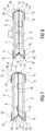
- the operating devices shown in the figures have a first flat component 2 facing an operator 1 a ferromagnetic material that is movable transversely to its surface extension.
- a second flat component 3 made of a ferromagnetic material is arranged immovably.
- the second flat component 3 has coil cores 4 at a distance from one another, which are directed towards the first flat component 2 and are formed in one piece with the second flat component 3 (in the Figures 9-13 not shown).
- the coil cores 4 are each enclosed by a pair of spiral-like flat coils 5, 5 '.
- the flat coils 5, 5 ' are printed on a printed circuit board 6 that extends over the surface of the flat components 2, 3 and is designed as a ceramic substrate, with the flat coils 5 on the first flat component 2 and the flat coils 5' on the second flat component 3 facing side are printed on the circuit board 6.
- the coil cores 4 protrude through recesses 7 correspondingly formed in the circuit board 6.
- the printed circuit board 6 carrying the flat coils 5, 5 ′ is glued onto the surface of the second flat component 3 facing the first flat component 2.
- the circuit board 6 could, however, also be connected to the second flat component 3 by a screw connection.
- first flat component 2 and the second flat component 3 are of the same at their mutually opposite edge regions, as Stamped and bent part formed from a spring plate connecting elements 9 encompassed, which in their in Figure 1
- the relaxed position shown have a connection area 11 perpendicular to the plane of the flat components 2, 3 and fastening ends 10 directed at right angles to the connection areas 11 at both ends.
- the fastening ends 10 are fastened to the surfaces of the first and second flat components 2 and 3 that are remote from one another.
- the resilient areas 12 are in the Figure 1 shown rest position without or without substantial spring tension. If the fastening ends 10 are deflected by the application of force from their orientation perpendicular to the connection area 11 ( Figure 2 ), a spring tension builds up in the resilient areas 12 which, after the application of force has ended, moves the connecting elements 9 and the first flat component 2 firmly connected to them back into the rest position.
- the connecting areas 14 between the resilient areas 12 have stiffeners 13 bent at right angles out of the plane of the spring surface, so that the connecting areas 11 are rigid.
- first and the second flat component 2 and 3 are connected to one another at their opposite ends by two identical connecting elements 9 'formed as stamped and bent parts from a spring plate.
- connection area 11 'to the fastening ends 10 form in the Figures 3 and 4 like in the Figures 1 and 2 Resilient areas 12, which in the Figure 3 and 5 are at least largely de-energized.
- FIGS. 6a to 6d show connecting elements 9 'in the rest position with different inclinations.
- FIGS 7 and 8 are the first and the second flat component 2 and 3 by two connecting elements formed as stamped and bent parts from a spring steel sheet 9 '', 9 '''connected to one another at their opposite ends.
- the connecting elements 9 ′′, 9 ′′ ′′ have fastening ends 10 with which they are fastened to the surfaces of the flat components 2 and 3 facing away from one another.
- each of the connecting elements 9 ′′, 9 ′′ ′′ are connected to one another via two connecting partial areas 14 having stiffeners 13.
- each connecting element 9 ′′, 9 ′′ ′′ stand in a V-shape to one another and are connected at their ends that are remote from one another to a respective fastening end 10 via resilient regions 12.
- the connecting elements 14 are connected to one another via a further resilient region 15.
- the “V” of the connecting elements 9 ′′, 9 ′′ ′′ are directed in the same direction parallel to the flat components 2 and 3 and are connected to one another at their further resilient areas 15 by a rigid coupling element 16.
- the first planar component 2 has a first connecting piece 18, on whose end directed towards the operator 1 the first fastening end 10 of a first connecting element 19 and on whose end protruding away from the operator 1 the first fastening end 10 of a second connecting element 20 is fastened.
- the second flat component 3 has a second connection piece 21, to whose end protruding away from the operator 1 the second fastening end 10 of the second connecting element 20 and to whose end facing the operator 1 the second fastening end 10 of the first connecting element 19 is fastened.
- the connecting elements 19 and 20 have connecting regions 11, fastening ends 10, stiffeners 13 and resilient regions 12.
- the end of the first connection piece 18 protruding away from the operator 1 protrudes with play through an opening 17 of the second flat component 3 and the end of the second connection piece 21 protruding towards the operator 1 protrudes with play through an opening 17 of the first flat component 2.
- the first and second connecting pieces 18 and 21 as well as the first and second connecting elements 19 and 20 form a first connecting unit 22.
- An identical connecting unit 22 ′ is arranged parallel to the first connecting unit 22, the two connecting units being connected to one another by three rigid transverse webs 23.
- a sensor system (not shown) detects that a finger of the operator 1 is touching the first flat component 2, the flat coils 5, 5 ′ are energized.
- the first flat component 2 simultaneously forms an operating element so that the operator senses the movement of the first flat component 2 haptically.
Description
Die Erfindung bezieht sich auf eine Bedieneinrichtung mit einem Bedienelement mit haptischer Rückmeldung, wobei das Bedienelement von einer Bedienperson mittels eines Eingabeorgans betätigbar ist, mit einem ersten und einem zweiten flächigen Bauteil, die mit ihren großen Flächen parallel zueinander ausgerichtet und relativ zueinander bewegbar sind, wobei das erste flächige Bauteil das Bedienelement bildet oder seine Bewegung ganz oder teilweise auf das Bedienelement überträgt.The invention relates to an operating device with an operating element with haptic feedback, wherein the operating element can be actuated by an operator by means of an input element, with a first and a second flat component, the large areas of which are aligned parallel to one another and can be moved relative to one another the first flat component forms the control element or transfers its movement in whole or in part to the control element.
Haptische Rückmeldungen von Bedienelementen werden vor allem dann gefordert, wenn ein Bediener den von ihm ausgeführten Bedienvorgang nicht direkt wahrnehmen kann. Während bei Bedienvorrichtungen mit elektromechanischen Schaltern für einen Bediener das Öffnen oder Schließen der Schaltkontakte durch eine sich ändernde Haptik des Bedienelements wahrnehmbar ist, ist dies bei elektronischen Schaltern nicht notwendigerweise vorhanden. Deshalb sind im Stand der Technik Bedienelemente bekannt, die mittels für den Bediener wahrnehmbaren Bewegungen des Bedienelements eine haptische Rückmeldung über einen erfolgten Bedienvorgang geben. Die bekannten haptischen Bedienelemente beispielsweise für sogenannte Touchscreens erfordern einen großen Bauraum, einen aufwendigen Antrieb und besondere konstruktive Maßnahmen, wenn diese beispielsweise in einem Umfeld eingesetzt werden sollen, das von besonders großen Temperaturunterschieden geprägt ist, wie es beispielsweise in einem Kraftfahrzeug der Fall ist, welches sowohl in arktischer Kälte als auch in sommerlicher Hitze seine Funktionsfähigkeit erhalten muss.Haptic feedback from operating elements is required above all when an operator cannot directly perceive the operating process carried out by him. While in operating devices with electromechanical switches the opening or closing of the switching contacts can be perceived by a changing feel of the operating element, this is not necessarily the case with electronic switches. For this reason, operating elements are known in the prior art which, by means of movements of the operating element that can be perceived by the operator, provide haptic feedback about an operation that has taken place. The known haptic controls, for example for so-called touchscreens, require a large installation space, a complex drive and special design measures if they are to be used, for example, in an environment that is characterized by particularly large temperature differences, as is the case, for example, in a motor vehicle, which must maintain its functionality both in arctic cold and in summer heat.
Um bei dem oder den ferromagnetischen flächigen Bauteilen eine definierte Kraft-Weg-Kennlinie zu erhalten, ist eine parallele Führung des oder der durch Kraftbeaufschlagung bewegbaren ferromagnetischen Bauteile notwendig. Diese Führung muss die Parallelität auch bei außermittiger Kraftbeaufschlagung ermöglichen und sollte insbesondere ein Verkippen des oder der ferromagnetischen flächigen Bauteile minimieren oder vermeiden.In order to obtain a defined force-displacement characteristic curve for the ferromagnetic flat component or components, a parallel guidance of the ferromagnetic component (s) that can be moved by the application of force is necessary. This leadership must be the Enable parallelism even with eccentric application of force and should in particular minimize or avoid tilting of the ferromagnetic flat component or components.
Bei einer Bedienvorrichtung der eingangs genannten Art ist es bekannt das oder die ferromagnetischen flächigen Bauteile in einer über die Tiefe des oder der ferromagnetischen flächigen Bauteile hinaus ausgedehnten Gleitführung zu führen. Die Berührungspunkte der Gleitführung bestimmen sich in Tiefe und Position in Abhängigkeit von den zu erwartenden Kräften und der maximal außermittigen Krafteinleitung. Daher ist bei einer derartigen Führung ein tiefer Bauraum erforderlich. Außerdem wird der haptische Eindruck bei Betätigung der Bedieneinrichtung durch die Reibung in der Führung negativ beeinflusst.In the case of an operating device of the type mentioned at the beginning, it is known to guide the ferromagnetic flat component or components in a sliding guide extending beyond the depth of the ferromagnetic flat component or components. The contact points of the sliding guide are determined in depth and position depending on the expected forces and the maximum off-center force application. A deep installation space is therefore required with such a guide. In addition, the haptic impression when the operating device is operated is negatively influenced by the friction in the guide.
Die
Die
Aufgabe der Erfindung ist es bei geringem Bauraumerfordernis und einfachem, flachen Aufbau eine zumindest weitgehend von einer Führung unbeeinflusste haptische Rückmeldung zu ermöglichen.The object of the invention is to enable haptic feedback that is at least largely uninfluenced by a guide, while requiring little installation space and with a simple, flat structure.
Diese Aufgabe wird erfindungsgemäß durch eine Bedieneinrichtung mit den Merkmalen des Anspruchs 1 gelöst.According to the invention, this object is achieved by an operating device having the features of claim 1.
Dabei können die flächigen Bauteile bei ihrer Bewegung zwischen der Ruheposition zusätzlich zu der den Abstand zwischen den flächigen Bauteilen verringernden Bewegung in ihren Ebenen relativ zueinander verschiebbar sein.In this case, the planar components can be displaceable in their planes relative to one another during their movement between the rest position in addition to the movement reducing the distance between the planar components.
Durch diese Ausbildung ist bei Parallelbewegung der flächigen Bauteile keine eine große Bautiefe erfordernde Führung nötig, so dass die Bautiefe und damit das Bauraumerfordernis der Bedieneinrichtung gering gehalten werden kann.Due to this design, no guide that requires a large installation depth is necessary for parallel movement of the flat components, see above that the overall depth and thus the space requirement of the operating device can be kept low.
Weiterhin werden die flächigen Bauteile immer parallel zueinander gehalten und insbesondere von der jeweiligen Art der Kraftbeaufschlagung abhängige Reibungseinflüsse vermieden.Furthermore, the flat components are always kept parallel to one another and, in particular, frictional influences that are dependent on the respective type of application of force are avoided.
Damit bleibt auch die haptische Rückmeldung aufgrund der Bewegung des ersten flächigen Bauteils von den Reibungseinflüssen unabhängig und feinfühlig.This means that the haptic feedback due to the movement of the first flat component remains independent and sensitive from the effects of friction.
In geringen Bauraum erfordernder einfacher Ausbildung bestehen erfindungsgemäß dabei die flächigen Bauteile ganz oder teilweise aus einem ferromagnetischen Werkstoff. Es ist wenigstens eine Spule zwischen den flächigen Bauteilen angeordnet, wobei durch Bestromung der Spule die flächigen Bauteile unter relativer Verschiebung in ihren Ebenen zueinander ihren Abstand zueinander verringernd bewegbar sind.In a simple design that requires little installation space, according to the invention, the flat components consist entirely or partially of a ferromagnetic material. At least one coil is arranged between the flat components, with the flat components being able to move, reducing their spacing from one another, with a relative displacement in their planes by energizing the coil.
Eine besonders geringe Bauhöhe wird dabei erreicht, wenn die Spule eine auf einer Leiterplatte angeordnete Flachspule ist.A particularly low overall height is achieved if the coil is a flat coil arranged on a printed circuit board.
Sind das erste flächige Bauteil und das zweite flächige Bauteil durch zwei Verbindungen miteinander verbunden, die jeweils mit gleichem Abstand und gleicher Richtung in Erstreckung der Ebenen der flächigen Bauteile mit ihrem einen Befestigungsende an dem ersten flächigen Bauteil und mit ihrem anderen Befestigungsende an dem zweiten flächigen Bauteil direkt oder indirekt befestigt sind, sich zwischen ihren Befestigungsenden und parallel zueinander erstrecken und nahe den Befestigungsenden federelastische Bereiche aufweisen sowie in ihrem Verbindungsbereich zwischen den Befestigungsenden biegesteif ausgebildet sind, wobei die federelastischen Bereiche auf die flächigen Bauteile eine voneinander weg bewegende Vorspannung ausüben, wird durch die gleichen Bauteile und somit bauteilsparend sowohl eine Parallelführung der flächigen Bauteile als auch eine Rückstellung in die Ruheposition erreicht.Are the first flat component and the second flat component connected to each other by two connections, each with the same distance and the same direction in the extension of the planes of the flat components with its one fastening end on the first flat component and with its other fastening end on the second flat component are fastened directly or indirectly, extend between their fastening ends and parallel to one another and have resilient areas near the fastening ends and are designed to be rigid in their connection area between the fastening ends, the resilient areas exerting a pretension moving away from one another on the flat components same components and thus both a component-saving Parallel guidance of the flat components as well as a return to the rest position is achieved.
Dazu kann in einem ersten Ausführungsbeispiel das erste flächige Bauteil als Verbindung ein erstes Verbindungsstück aufweisen, an dessen zu der Bedienperson hin gerichteten Ende das erste Befestigungsende eines ersten Verbindungselements und an dessen von der Bedienperson wegragenden Ende das erste Befestigungsende eines zweiten Verbindungselements befestigt ist, und dass das zweite flächige Bauteil als Verbindung ein zweites Verbindungsstück aufweist, an dessen von der Bedienperson wegragenden Ende das zweite Befestigungsende des zweiten Verbindungselements und an dessen zu der Bedienperson hin gerichteten Ende das zweite Befestigungsende des ersten Verbindungselements befestigt ist, wobei das von der Bedienperson wegragende Ende des ersten Verbindungsstücks mit Spiel durch eine Öffnung des zweiten flächigen Bauteils ragen und das zu der Bedienperson hin ragende Ende des zweiten Verbindungsstücks mit Spiel durch eine Öffnung des ersten flächigen Bauteils ragen kann.For this purpose, in a first exemplary embodiment, the first flat component can have a first connecting piece as a connection, at whose end directed towards the operator the first fastening end of a first connecting element is fastened and at whose end projecting away from the operator the first fastening end of a second connecting element is fastened, and that the second flat component has a second connecting piece as a connection, to the end of which protruding from the operator the second fastening end of the second connecting element and to whose end facing the operator the second fastening end of the first connecting element is fastened, the end of the protruding from the operator first connecting piece protrude with play through an opening of the second flat component and the end of the second connecting piece protruding towards the operator can protrude with play through an opening of the first flat component.
Ein Verkippen quer zur Erstreckungsrichtung der Verbindungselemente wird dadurch vermieden, dass parallel zu einer aus erstem und zweiten Verbindungsstück und erstem und zweitem Verbindungselement bestehenden Verbindungseinheit eine zweite gleiche Verbindungseinheit angeordnet ist, wobei die ersten Verbindungselemente und/oder die zweiten Verbindungselemente der beiden Verbindungseinheiten durch ein oder mehrere starre Querstege miteinander verbunden sind.Tilting transversely to the direction of extension of the connecting elements is avoided by arranging a second identical connecting unit parallel to a connecting unit consisting of a first and second connecting piece and first and second connecting element, the first connecting elements and / or the second connecting elements of the two connecting units being connected by one or several rigid transverse webs are connected to one another.
In einem weiteren Ausführungsbeispiel können die Verbindungsbereiche sich bei unbestromter Flachspule rechtwinklig zur Ebene der flächigen Bauteile und bei bestromter Flachspule zur Ebene der Bauteile geneigt erstrecken.In a further exemplary embodiment, when the flat coil is de-energized, the connection areas can extend at right angles to the plane of the flat components and, when the flat coil is energized, inclined to the plane of the components.
Erstrecken sich die Verbindungsbereiche bei unbestromter Flachspule mit einer größeren Neigung zur Ebene der flächigen Bauteile als bei bestromter Flachspule, so wird die Bewegungsrichtung der bewegten flächigen Bauteile um so mehr zu einer normalen zur Ebene der ausgerichteten Bewegung umgeformt, je größer die Neigung bereits in der Ruheposition ist.If the connection areas extend when the flat coil is de-energized with a greater inclination to the plane of the flat components than when the flat coil is energized, the direction of movement becomes of the moving planar components are transformed into a normal to the plane of the aligned movement, the greater the inclination is already in the rest position.
Zu einer Bewegungsrichtung der bewegten flächigen Bauteile nur rechtwinklig zur Ebene der flächigen Bauteile führt es, wenn die Verbindungsbereiche aus zwei über einen weiteren federelastischen Bereich miteinander verbundenen, biegesteifen Verbindungsteilbereichen bestehen, die sich gegenüber der Ebene der flächigen Bauteile unter Winkeln geneigt erstrecken, deren Summe ein Komplimentärwinkel zur Ebene der flächigen Bauteile ist und die über ein sich parallel zur Ebene der flächigen Bauteile erstreckendes Koppelelement mit einander verbunden sind.A direction of movement of the moving planar components only at right angles to the plane of the planar components results when the connection areas consist of two rigid connecting subareas connected to one another via a further resilient area, which extend inclined at angles relative to the plane of the planar components, their sum Complementary angle to the plane of the flat components and which are connected to one another via a coupling element extending parallel to the plane of the flat components.
Besonders einfach herstellbar und die erforderlichen Bauteile reduzierend ist es, wenn die Verbindungselemente als Stanz-Biegeteil aus Blech ausgebildet sind.It is particularly easy to manufacture and reduce the number of components required if the connecting elements are designed as stamped and bent parts made of sheet metal.
Dabei sind in einfacher Weise die Verbindungsbereiche und Verbindungsteilbereiche dadurch biegesteif ausgebildet, dass die Verbindungselemente im Verbindungsbereich oder in den Verbindungsteilbereichen entlang der Längskanten zwischen den federelastischen Bereichen oder zwischen den federelastischen Bereichen und dem weiteren federelastischen Bereich aus der Blechebene abgebogen sind.The connecting areas and connecting subareas are designed to be rigid in a simple manner in that the connecting elements in the connecting area or in the connecting subareas are bent out of the sheet metal plane along the longitudinal edges between the resilient areas or between the resilient areas and the further resilient area.
Zu einer anderen ebenso auf einfache Art erreichbaren Biegesteifigkeit der Verbindungsbereiche und Verbindungsteilbereiche führt es, wenn die Verbindungselemente im Verbindungsbereich oder in den Verbindungsteilbereichen eine oder mehrere sich entlang ihrer Längserstreckung zwischen den federelastischen Bereichen erstreckende Einprägungen aufweist.Another easily achievable bending stiffness of the connecting areas and connecting subareas is achieved if the connecting elements in the connecting area or in the connecting subareas have one or more embossings extending along their length between the resilient areas.
Um die Bauhöhe der Bedieneinrichtung weiterhin zu minimieren, kann die die Flachspule tragende Leiterplatte fest auf der dem ersten flächigen Bauteil zugewandten Fläche des zweiten flächigen Bauteils angeordnet sein.In order to further minimize the overall height of the operating device, the printed circuit board carrying the flat coil can be arranged fixedly on the surface of the second flat component facing the first flat component.
Durch diese Ausbildung muss die Leiterplatte nicht mehr eine solche Steifheit aufweisen, dass sie formstabil planar die Flachspule trägt, da sie nun ihre formstabile Eigenschaft von dem formstabilen ersten flächigen Bauteil erhält.As a result of this design, the circuit board no longer has to have such rigidity that it carries the flat coil in a dimensionally stable planar manner, since it now receives its dimensionally stable property from the dimensionally stable first flat component.
Die Dicke der Leiterplatte muss nur noch eine sichere Isolation zum zweiten flächigen Bauteil gewährleisten und kann so minimalisiert sein.The thickness of the circuit board only has to ensure reliable insulation from the second flat component and can thus be minimized.
Sowohl die durch das erste flächige Bauteil bedingte Ebenheit der Leiterplatte, die Vermeidung von Welligkeiten der Leiterplatte sowie deren geringe Dicke ermöglichen es den Abstand zwischen den beiden flächigen Bauteilen und damit auch die Gesamtbauhöhe der Bedieneinrichtung gering zu dimensionieren sowie bei gegebener zur Verfügung stehender Energie größere Stellkräfte zu erzeugen.Both the flatness of the printed circuit board caused by the first flat component, the avoidance of waviness in the printed circuit board and its small thickness make it possible to dimension the distance between the two flat components and thus also the overall height of the operating device to be small and, given the energy available, greater actuating forces to create.
Durch das Bestromen der Spule wird ein Magnetfeld aufgebaut und die beiden flächigen Bauteile zueinander gezogen.When the coil is energized, a magnetic field is built up and the two flat components are drawn towards each other.
Diese Bewegung ist für das Eingabeorgan wie z.B. einen Finger einer Bedienperson direkt oder indirekt wahrnehmbar.This movement is for the input organ such as e.g. a finger of an operator directly or indirectly perceptible.
Besonders einfach und dauerhaft ist die Flachspule herstellbar, wenn sie aus auf der Leiterplatte angeordneten Leiterbahnen besteht. Dabei kann die Leiterplatte kupferkaschiert und derart geätzt sein, dass die Leiterbahnen in vorzugsweise spiralförmiger Spulenbahn übrig bleiben.The flat coil can be manufactured particularly easily and permanently if it consists of conductor tracks arranged on the printed circuit board. In this case, the circuit board can be copper-clad and etched in such a way that the conductor tracks remain in a preferably spiral-shaped coil track.
Anstelle des Ätzens der Leiterbahnen können diese beispielsweise auch durch ein Bedrucken der Leiterplatte mit einem Leiterbahnmaterial wie Silberpaste erzeugt werden.Instead of etching the conductor tracks, they can also be produced, for example, by printing the circuit board with a conductor track material such as silver paste.
Zur Konzentration des magnetischen Flusses weist vorzugsweise die Flachspule einen rechtwinklig zur Ebene der flächigen Bauteile sich erstreckenden Spulenkern auf.To concentrate the magnetic flux, the flat coil preferably has a coil core extending at right angles to the plane of the flat components.
Aufgrund des geringen Abstandes zwischen den beiden flächigen Bauteilen ist auch die Höhe des Polschuhes gering. Weiterhin kann aufgrund der geringen einzuhaltenden Toleranzen der Polschuh bis nahe an das erste Bauteil heranreichen, wodurch der magnetische Fluss erhöht wird.Due to the small distance between the two flat components, the height of the pole piece is also low. Furthermore, due to the small tolerances to be observed, the pole piece can reach close to the first component, whereby the magnetic flux is increased.
Ist dabei der Spulenkern einteilig mit einem der flächigen Bauteile ausgebildet, so reduziert sich die Anzahl der Bauteile und der Montageaufwand.If the coil core is designed in one piece with one of the flat components, the number of components and the assembly effort are reduced.
Zur planen Befestigung der Leiterplatte auf dem zweiten flächigen Bauteil kann die Leiterplatte mittels einer Klebeschicht auf dem zweiten flächigen Bauteil angeordnet sein.For planar attachment of the circuit board to the second flat component, the circuit board can be arranged on the second flat component by means of an adhesive layer.
Eine weitere Reduzierung der Bauhöhe wird dadurch erreicht, dass die Leiterplatte in Schichttechnik, insbesondere in Dickschichttechnik auf dem zweiten flächigen Bauteil aufgetragen ist.A further reduction in the overall height is achieved in that the printed circuit board is applied to the second flat component using layer technology, in particular using thick layer technology.
Vorzugsweise ist das zweite flächige Bauteil nichtbeweglich angeordnet, so dass bei einer Bestromung der Flachspule nur das erste Bauteil in Richtung auf das zweite flächige Bauteil bewegt wird.The second flat component is preferably arranged to be immovable, so that when the flat coil is energized, only the first component is moved in the direction of the second flat component.
Zur Bewegung der flächigen Bauteile in ihre Ruheposition bei nichtbestromter Flachspule können das erste flächige Bauteil und das zweite flächige Bauteil bei unbestromter Flachspule von einem Federelement bis zu einem bestimmten Maximalabstand voneinander weg bewegbar sein, wobei in einfacher Ausbildung der Maximalabstand der beiden flächigen Bauteile durch Anschläge bestimmt ist.To move the flat components into their rest position when the flat coil is not energized, the first flat component and the second flat component can be moved away from each other by a spring element up to a certain maximum distance when the flat coil is not energized, the maximum distance between the two flat components being determined by stops in a simple design is.
Das Bedienelement kann als Anzeige ausgebildet sein. Diese Anzeige kann im einfachsten Fall beispielsweise aus einer Bedruckung mit verschiedenen Ziffern in Form einer Telefontastatur ausgestaltet sein. So können beispielsweise verschiedene Ziffern ausgewählt werden, wenn mit dem Bedienorgan das Bedienelement an der entsprechenden Ziffer berührt wird und die Anzeige eine entsprechende Vorrichtung aufweist, mit der die Position des Eingabeorgans auf der Anzeige bestimmbar ist.The control element can be designed as a display. In the simplest case, this display can be designed, for example, from printing with different digits in the form of a telephone keypad. For example, different digits can be selected when using the control unit Control element is touched on the corresponding digit and the display has a corresponding device with which the position of the input member on the display can be determined.
Die Anzeige kann dabei als elektrooptische Anzeige ausgebildet sein, bei der z.B. verschiedene Menüs, Untermenüs oder Einzelwerte auf der Anzeige dargestellt werden können, die dann durch eine entsprechende Berührung der Anzeige an der entsprechenden Position der Darstellung des auszuwählenden Menüs, Untermenüs oder Wertes detektiert werden. Derartige optoelektronische Anzeigen können beispielsweise als Leuchtdiodenmatrix, organisches Leuchtdiodendisplay oder Flüssigkristalldisplay ausgebildet sein und sind bereits als sogenannte Touchscreens bekannt.The display can be designed as an electro-optical display in which e.g. different menus, submenus or individual values can be shown on the display, which are then detected by touching the display at the corresponding position of the display of the menu, submenu or value to be selected. Such optoelectronic displays can be designed, for example, as a light emitting diode matrix, organic light emitting diode display or liquid crystal display and are already known as so-called touchscreens.
Die Flachspulen werden zum Bewegen der flächigen Bauteile zueinander mit einem Gleichstrom oder einem niederfrequenten Wechselstrom bestromt. Zusätzlich kann dieser Strom mit einer Frequenz im Hörbereich, wie beispielsweise 1 Kilohertz moduliert werden, so dass diese Frequenz zusätzlich hörbar ist. So kann ein Klick hörbar sein, der sich anhört, als sei ein elektromagnetischer Schalter geöffnet oder geschlossen worden.The flat coils are energized with a direct current or a low-frequency alternating current in order to move the flat components relative to one another. In addition, this current can be modulated with a frequency in the audible range, such as 1 kilohertz, so that this frequency can also be heard. For example, a click can be heard that sounds like an electromagnetic switch has been opened or closed.
Ausführungsbeispiele der Erfindung sind in der Zeichnung dargestellt und werden im Folgenden näher beschrieben. Es zeigen:
- Figur 1
- eine Seitenansicht im Schnitt eines ersten Ausführungsbeispiels einer Bedieneinrichtungin nicht bestromter Ruheposition,
Figur 2- die Bedieneinrichtung nach
Figur 1 in bestromter Betätigungsposition, Figur 3- eine Seitenansicht im Schnitt eines zweiten Ausführungsbeispiels einer Bedieneinrichtung in nicht bestromter Ruheposition,
Figur 4- die Bedieneinrichtung nach
Figur 3 Figur 5- eine Seitenansicht im Schnitt eines dritten Ausführungsbeispiels einer Bedieneinrichtung in nicht bestromter Ruheposition,
- Figuren
- vier Ausführungsbeispiele von Verbindungselementen 6a - 6d in Ruheposition,
- Figur 7
- eine Seitenansicht im Schnitt eines vierten Ausführungsbeispiels einer Bedieneinrichtung in nicht bestromter Ruheposition,
Figur 8- die Bedieneinrichtung nach
Figur 7 in bestromter Betätigungsposition, Figur 9- eine Seitenansicht im Schnitt eines fünften Ausführungsbeispiels einer Bedieneinrichtung in nicht bestromter Ruheposition,
Figur 10- eine perspektivische Draufsicht der Bedieneinrichtung entsprechend
Figur 9 , Figur 11- eine perspektivische Unteransicht der Bedieneinrichtung entsprechend
Figur 9 , Figur 12- eine erste perspektivische Ansicht einer Verbindungseinheit der Bedieneinrichtung nach
Figur 10 , Figur 13- eine zweite perspektivische Ansicht einer Verbindungseinheit der Bedieneinrichtung nach
Figur 10 .
- Figure 1
- a side view in section of a first embodiment of an operating device in the non-energized rest position,
- Figure 2
- the control device according to
Figure 1 in energized actuation position, - Figure 3
- a side view in section of a second embodiment of an operating device in a non-energized rest position,
- Figure 4
- the control device according to
Figure 3 in energized actuation position, - Figure 5
- a side view in section of a third embodiment of an operating device in a non-energized rest position,
- characters
- four exemplary embodiments of connecting elements 6a-6d in the rest position,
- Figure 7
- a side view in section of a fourth embodiment of an operating device in a non-energized rest position,
- Figure 8
- the control device according to
Figure 7 in energized actuation position, - Figure 9
- a side view in section of a fifth embodiment of an operating device in a non-energized rest position,
- Figure 10
- a perspective top view of the operating device accordingly
Figure 9 , - Figure 11
- a perspective bottom view of the control device accordingly
Figure 9 , - Figure 12
- a first perspective view of a connection unit of the operating device according to
Figure 10 , - Figure 13
- a second perspective view of a connection unit of the operating device according to
Figure 10 .
Die in den Figuren dargestellte Bedieneinrichtungen weisen ein einer Bedienperson 1 zugewandtes erstes flächiges Bauteil 2 aus einem ferromagnetischen Werkstoff auf, das quer zu seiner Flächenerstreckung beweglich ist.The operating devices shown in the figures have a first
Parallel dazu ist ein zweites flächiges Bauteil 3 aus einem ferromagnetischen Werkstoff nichtbeweglich angeordnet.In parallel, a second
Das zweite flächige Bauteil 3 weist in Abständen zueinander Spulenkerne 4 auf, die zu dem ersten flächigen Bauteil 2 gerichtet und mit dem zweiten flächigen Bauteil 3 einteilig ausgebildet sind (in den
Die Spulenkerne 4 sind jeweils von einem Paar spiralartiger Flachspulen 5, 5' umschlossen.The
Die Flachspulen 5, 5' sind auf einer sich über die Fläche der flächigen Bauteile 2, 3 erstreckenden, als Keramiksubstrat ausgebildeten Leiterplatte 6 aufgedruckt, wobei die Flachspulen 5 auf der dem ersten flächigen Bauteil 2 und die Flachspulen 5' auf der dem zweiten flächigen Bauteil 3 zugewandten Seite auf die Leiterplatte 6 aufgedruckt sind.The
Die Spulenkerne 4 ragen durch entsprechend in der Leiterplatte 6 ausgebildete Ausnehmungen 7.The
Mittels einer Klebeschicht 8 ist die die Flachspulen 5, 5' tragende Leiterplatte 6 auf der dem ersten flächigen Bauteil 2 zugewandte Fläche des zweiten flächigen Bauteils 3 aufgeklebt.By means of an
Die Leiterplatte 6 könnte aber auch durch eine Schraubverbindung mit dem zweiten flächigen Bauteil 3 verbunden sein.The circuit board 6 could, however, also be connected to the second
Zur besseren Übersichtlichkeit sind die Flachspulen 5, 5', die Leiterplatte 6 und die Klebeschicht 8 nur in
Bei dem Ausführungsbeispiel der
Die Befestigungsenden 10 sind an den einander entfernten Flächen der ersten und zweiten flächigen Bauteile 2 und 3 befestigt.The fastening ends 10 are fastened to the surfaces of the first and second
Die rechtwinkligen Übergänge von den Verbindungsbereichen 11 zu den Befestigungsenden 10 der aus einem Federblech bestehenden Verbindungselemente 9 bilden federelastische Bereiche 12.The right-angled transitions from the connecting
Die federelastischen Bereiche 12 sind in der in
Entlang ihrer Längskanten weisen die Verbindungsbereiche 14 zwischen den federelastischen Bereichen 12 aus der Ebene der Federfläche rechtwinklig abgebogene Versteifungen 13 auf, so dass die Verbindungsbereiche 11 biegesteif sind.Along their longitudinal edges, the connecting
Bei dem Ausführungsbeispiel der
In der in
In
Die Übergänge von dem Verbindungsbereich 11' zu den Befestigungsenden 10 bilden in den
Bei Auslenkung der Verbindungselemente 9' aus der Ruheposition wird wie bei den Verbindungselementen 9 eine Federspannung in den federelastischen Bereichen 12 aufgebaut, die die Verbindungselemente 9' wieder in ihre Ruheposition zurückstellen möchte.When the connecting elements 9 'are deflected from the rest position, a spring tension is built up in the
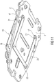
Die
Bei dem Ausführungsbeispiel der
Die Verbindungselemente 9'', 9''' weisen Befestigungsenden 10 auf, mit denen sie an den einander abgewandten Flächen der flächigen Bauteile 2 und 3 befestigt sind.The connecting
Die Befestigungsenden 10 jedes der Verbindungselemente 9'', 9''' sind über zwei Versteifungen 13 aufweisende Verbindungsteilbereiche 14 miteinander verbunden.The fastening ends 10 of each of the connecting
Die beiden Verbindungsteilbereiche 14 jedes Verbindungselements 9'', 9''' stehen V-förmig zueinander und sind mit ihren einander entfernten Enden über federelastische Bereiche 12 jeweils mit einem Befestigungsende 10 verbunden.The two connecting
An den einander zugewandten Enden sind die Verbindungselemente 14 über einen weiteren federelastischen Bereich 15 miteinander verbunden.At the ends facing each other, the connecting
Die "V" der Verbindungselemente 9'', 9''' sind in die gleiche Richtung parallel zu den flächigen Bauteilen 2 und 3 gerichtet und an ihren weiteren federelastischen Bereichen 15 durch ein starres Koppelelement 16 miteinander verbunden.The “V” of the connecting
Bei dem Ausführungsbeispiel der
Wie bei den vorherigen Ausführungsbeispielen weisen die Verbindungselemente 19 und 20 Verbindungsbereiche 11, Befestigungsenden 10, Versteifungen 13 und federelastische Bereiche 12 auf.As in the previous exemplary embodiments, the connecting
Das von der Bedienperson 1 wegragende Ende des ersten Verbindungsstücks 18 ragt dabei mit Spiel durch eine Öffnung 17 des zweiten flächigen Bauteils 3 und das zu der Bedienperson 1 hin ragende Ende des zweiten Verbindungsstücks 21 ragt mit Spiel durch eine Öffnung 17 des ersten flächigen Bauteils 2.The end of the
Das erste und zweite Verbindungsstück 18 und 21 sowie das erste und zweite Verbindungselement 19 und 20 bilden eine erste Verbindungseinheit 22. Parallel zur der ersten Verbindungseinheit 22 ist eine gleiche Verbindungseinheit 22' angeordnet, wobei die beiden Verbindungseinheiten durch drei starre Querstege 23 miteinander verbunden sind.The first and second connecting
Wenn von einer nicht dargestellten Sensorik erkannt wird, dass ein Finger der Bedienperson 1 das erste flächige Bauteil 2 berührt, werden die Flachspulen 5, 5' bestromt.If a sensor system (not shown) detects that a finger of the operator 1 is touching the first
Werden die Flachspulen 5, 5' von dem Strom durchflossen, wird ein magnetischer Fluss in die flächigen Bauteile 2, 3 eingeprägt und so ein magnetischer Kreis geschlossen, so dass die beiden flächigen Bauteile 2, 3 entgegen der Kraft der federelastischen Bereiche 12 parallel relativ zueinander gezogen werden, ohne sich zu berühren.If the current flows through the
Bei Beendigung des Stromdurchflusses durch die Flachspulen 5, 5' werden die flächigen Bauteile 2, 3 durch die federelastischen Bereiche 12 wieder in ihre Ruheposition zurückbewegt.When the current flow through the
Bei den Ausführungsbeispielen der
Das erste flächige Bauteil 2 bildet gleichzeitig ein Bedienelement, so dass die Bedienperson die Bewegung des ersten flächigen Bauteils 2 haptisch erfasst.The first
Claims (13)
- Operator control device having an operator control element with haptic feedback, wherein the operator control element can be activated by an operator (1) by means of an input member, having a first and a second planar component which are oriented parallel to one another with their large surfaces and can move relative to one another, wherein the first planar component forms the operator control element or transmits its movement entirely or partially to the operator control element, wherein the planar components (2, 3) are guided between a position of rest and an activation position while maintaining their parallel position with respect to one another, wherein in the activation position the distance between the two planar components (2, 3) is smaller than in the position of rest, and the two planar components (2, 3) are spring loaded in their position of rest, and wherein the planar components (2, 3) can be driven by an actuator counter to the spring force such that they can be moved out of their position of rest into their activation position, wherein the planar components (2, 3) are composed entirely or partially of a ferromagnetic material, characterized in that at least one coil is arranged between the planar components (2, 3), wherein by energizing the coil the planar components (2, 3) can be moved with relative displacement in their planes with respect to one another such that their distance from one another is reduced, in that the coil is a flat coil (5, 5') which is arranged on a printed circuit board (6).
- Operator control device according to Claim 1, characterized in that the first planar component (2) and the second planar component (3) are connected to one another by two connections which are each directly or indirectly attached at the same distance and in the same direction in the extent of the planes of the planar components (2, 3) to the first planar component (2) by their one attachment end (10) and to the second planar component (3) by their other attachment end (10), extend between their attachment ends (10) and parallel to one another and have spring-elastic regions (12) near to the attachment ends (10), and are of flexurally rigid design in their connecting region (11, 11') between the attachment ends (10), wherein the spring-elastic regions (12) exert on the planar components (2, 3) a prestress moving away from one another.
- Operator control device according to Claim 2, characterized in that the first planar component (2) has as a connection a first connecting piece (18) to whose end directed toward the operator (1) the first attachment end (10) of a first connecting element (19) is attached, and to whose end projecting away from the operator (1) the first attachment end (10) of a second connecting element (20) is attached, and in that the second planar component (3) has as a connection a second connecting piece (21) to whose end projecting away from the operator (1) the second attachment end (10) of the second connecting element (20) is attached, and to whose end directed toward the operator (1) the second attachment end (10) of the first connecting element (19) is attached.
- Operator control device according to Claim 3, characterized in that the end, projecting away from the operator (1), of the first connecting piece (18) projects with play through an opening (17) in the second planar component (3), and the end, projecting toward the operator (1), of the second connecting piece (21) projects with play through an opening (17) in the first planar component (2).
- Operator control device according to either of Claims 3 and 4, characterized in that a second identical connecting unit (22') is arranged parallel to a connecting unit (22) composed of first and second connecting pieces (18, 21) and first and second connecting elements (19, 20), wherein the first connecting elements (19) and/or the second connecting elements (20) of the two connecting units (22, 22') are connected to one another by one or more rigid crossmembers (23).
- Operator control device according to Claim 2, characterized in that the connecting regions (11') extend with a greater incline with respect to the plane of the planar components (2, 3) when the flat coil is not energized than when the flat coil is energized.
- Operator control device according to Claim 2, characterized in that the connecting regions are composed of two flexurally rigid connecting partial regions (14) which are connected to one another via a further spring-elastic region (15) and extend at an incline with respect to the plane of the planar components (2, 3) at angles whose sum is a complementary angle with respect to the plane of the planar components (2, 3), and which connecting partial regions (14) are connected to one another via a coupling element (16) which extends parallel to the plane of the planar components (2, 3).
- Operator control device according to one of the preceding claims, characterized in that the connecting elements (9, 9', 9'', 9''') are embodied as a punched bent part made of sheet metal.
- Operator control device according to Claim 8, characterized in that the connecting elements (9, 9', 9'', 9''') are bent out of the plane of the sheet metal in the connecting region (11, 11') or in the connecting partial regions (14) along the longitudinal edges between the spring-elastic regions (12) or between the spring-elastic regions (12) and the further spring-elastic region (15).
- Operator control device according to Claim 8, characterized in that the connecting elements have one or more impressions extending along their longitudinal extent between the spring-elastic regions, in the connecting region or in the connecting partial regions.
- Operator control device according to one of the preceding claims, characterized in that the printed circuit board (6) which supports the flat coil (5, 5') is fixedly arranged on the surface of the second planar component (3) facing the first planar component (2).
- Operator control device according to Claim 11, characterized in that the printed circuit board (6) is arranged on the second planar component (3) by means of an adhesive layer (8) or is applied to the second planar component using film technology.
- Operator control device according to one of the preceding claims, characterized in that the operator control element is embodied as a display.
Applications Claiming Priority (2)
| Application Number | Priority Date | Filing Date | Title |
|---|---|---|---|
| DE102011082143A DE102011082143A1 (en) | 2011-09-05 | 2011-09-05 | operating device |
| PCT/EP2012/066861 WO2013034483A1 (en) | 2011-09-05 | 2012-08-30 | Operating arrangement |
Publications (2)
| Publication Number | Publication Date |
|---|---|
| EP2754006A1 EP2754006A1 (en) | 2014-07-16 |
| EP2754006B1 true EP2754006B1 (en) | 2020-11-25 |
Family
ID=46851428
Family Applications (1)
| Application Number | Title | Priority Date | Filing Date |
|---|---|---|---|
| EP12759056.0A Active EP2754006B1 (en) | 2011-09-05 | 2012-08-30 | Operating arrangement |
Country Status (4)
| Country | Link |
|---|---|
| US (1) | US9746847B2 (en) |
| EP (1) | EP2754006B1 (en) |
| DE (1) | DE102011082143A1 (en) |
| WO (1) | WO2013034483A1 (en) |
Families Citing this family (6)
| Publication number | Priority date | Publication date | Assignee | Title |
|---|---|---|---|---|
| JP6543328B2 (en) | 2014-07-22 | 2019-07-10 | ベーア−ヘラー サーモコントロール ゲーエムベーハー | Control unit for electrical equipment |
| CN108351663B (en) * | 2015-10-23 | 2020-08-28 | 贝尔-赫拉恒温控制有限公司 | Operating unit for a vehicle element, in particular a heating system, a ventilation system and/or an air conditioning system |
| DE102015222714A1 (en) * | 2015-11-18 | 2017-05-18 | Robert Bosch Gmbh | operating device |
| EP3608747B1 (en) * | 2018-08-06 | 2022-09-14 | Robert Bosch GmbH | Operating device for a vehicle, vehicle |
| DE102022100993B4 (en) | 2022-01-17 | 2023-10-26 | Behr-Hella Thermocontrol Gmbh | Control unit for a vehicle, in particular for one or more vehicle components |
| DE102022101657A1 (en) * | 2022-01-25 | 2023-07-27 | Valeo Schalter Und Sensoren Gmbh | Input device for a motor vehicle |
Family Cites Families (21)
| Publication number | Priority date | Publication date | Assignee | Title |
|---|---|---|---|---|
| KR19980032013A (en) * | 1995-12-15 | 1998-07-25 | 모리시타요오이찌 | Vibration generator |
| JP3949912B2 (en) * | 2000-08-08 | 2007-07-25 | 株式会社エヌ・ティ・ティ・ドコモ | Portable electronic device, electronic device, vibration generator, notification method by vibration and notification control method |
| JP2003154315A (en) * | 2001-11-22 | 2003-05-27 | Matsushita Electric Ind Co Ltd | Vibratory linear actuator |
| JP4500485B2 (en) * | 2002-08-28 | 2010-07-14 | 株式会社日立製作所 | Display device with touch panel |
| KR100549880B1 (en) * | 2003-07-05 | 2006-02-06 | 엘지이노텍 주식회사 | Vibrator structure |
| KR100735299B1 (en) * | 2004-06-23 | 2007-07-03 | 삼성전기주식회사 | A vertical vibrator |
| FR2875024B1 (en) * | 2004-09-09 | 2007-06-08 | Itt Mfg Enterprises Inc | TOUCH SLAB INCLUDING MEANS FOR PRODUCING A MECHANICAL IMPULSE IN RESPONSE TO A CONTROL ACTION, AND ARRANGEMENT FOR THE ASSEMBLY OF THIS SLAB |
| US8232969B2 (en) * | 2004-10-08 | 2012-07-31 | Immersion Corporation | Haptic feedback for button and scrolling action simulation in touch input devices |
| US7825903B2 (en) * | 2005-05-12 | 2010-11-02 | Immersion Corporation | Method and apparatus for providing haptic effects to a touch panel |
| DE102005054677A1 (en) * | 2005-11-16 | 2007-06-06 | Siemens Ag | Touch-sensitive control unit with haptic feedback |
| GB2446702A (en) * | 2007-02-13 | 2008-08-20 | Qrg Ltd | Touch Control Panel with Pressure Sensor |
| US9056549B2 (en) * | 2008-03-28 | 2015-06-16 | Denso International America, Inc. | Haptic tracking remote control for driver information center system |
| JP5033078B2 (en) * | 2008-08-06 | 2012-09-26 | 株式会社ジャパンディスプレイイースト | Display device |
| DE102008058568A1 (en) * | 2008-11-21 | 2010-05-27 | Continental Automotive Gmbh | Haptic control device |
| US9684375B2 (en) * | 2008-12-12 | 2017-06-20 | Immersion Corporation | Systems and methods for stabilizing a haptic touch panel or touch surface |
| US8760413B2 (en) * | 2009-01-08 | 2014-06-24 | Synaptics Incorporated | Tactile surface |
| DE102009036860A1 (en) * | 2009-08-10 | 2011-03-03 | Siemens Aktiengesellschaft | Operating unit, device and procedure |
| DE102010007486A1 (en) * | 2010-02-09 | 2011-08-11 | Continental Automotive GmbH, 30165 | operating device |
| KR101122797B1 (en) * | 2010-04-26 | 2012-03-21 | 엘지이노텍 주식회사 | Linear vibrator having wideband |
| US20110291947A1 (en) * | 2010-05-27 | 2011-12-01 | Nigel Patrick Pemberton-Pigott | Touch-Sensitive Display |
| KR101080641B1 (en) * | 2010-06-30 | 2011-11-08 | 주식회사 하이소닉 | Portable terminal with haptic module |
-
2011
- 2011-09-05 DE DE102011082143A patent/DE102011082143A1/en not_active Withdrawn
-
2012
- 2012-08-30 EP EP12759056.0A patent/EP2754006B1/en active Active
- 2012-08-30 US US14/342,982 patent/US9746847B2/en active Active
- 2012-08-30 WO PCT/EP2012/066861 patent/WO2013034483A1/en active Application Filing
Non-Patent Citations (1)
| Title |
|---|
| None * |
Also Published As
| Publication number | Publication date |
|---|---|
| DE102011082143A1 (en) | 2013-03-07 |
| US9746847B2 (en) | 2017-08-29 |
| EP2754006A1 (en) | 2014-07-16 |
| US20140207268A1 (en) | 2014-07-24 |
| WO2013034483A1 (en) | 2013-03-14 |
Similar Documents
| Publication | Publication Date | Title |
|---|---|---|
| EP2754006B1 (en) | Operating arrangement | |
| EP2734910B1 (en) | Operator control device | |
| EP2920665B1 (en) | Operating device for a vehicle component | |
| WO2011098453A1 (en) | Operating device | |
| EP2745187B1 (en) | Operator control device | |
| DE102011079711B4 (en) | operating device | |
| EP2197115B1 (en) | Operating device with at least one pressure switch | |
| DE102010041345A1 (en) | Device for fastening a haptic surface | |
| DE102007054778A1 (en) | Operating device with at least one pressure switch | |
| WO2017045975A1 (en) | Control unit for a vehicle | |
| EP3774433B1 (en) | Control device for a vehicle | |
| EP3455868B1 (en) | Electromagnetic feedback actuator for an operating element and arrangement having at least one electromagnetic feedback actuator | |
| DE2214105B2 (en) | TORQUE SWITCH WITH A CONTACT AND AN ACTUATION BUTTON THAT CAN BE PUSHED INTO A SPRING FORCE | |
| EP2754244B1 (en) | Operating device | |
| EP2920553B1 (en) | Capacitive sensor for detecting a relative movement of two adjacent bodies | |
| DE102012219474A1 (en) | Pushbutton used as stroke key in video processing apparatus has spring unit which is moved with respect to base portion, so that spring unit exerts elastic restoring force between base portion and upper portion | |
| EP2071276B1 (en) | Sensor | |
| DE102009025458B4 (en) | sensor | |
| EP1905054A1 (en) | Bistable rocker switch having a contact pad | |
| EP3152837B1 (en) | Device for controlling multiple functions in a motor vehicle | |
| WO2024052312A1 (en) | Operating device for a vehicle | |
| WO2019048681A1 (en) | Operating device having a handle, which can be tilted in several directions, with haptic feedback | |
| DE102008020132A1 (en) | Device for unidirectional movement of fluids or fluid drops by effect of electrowetting, comprises electrode, entry area, main area and exit area, where main area expands for moving fluid drops |
Legal Events
| Date | Code | Title | Description |
|---|---|---|---|
| PUAI | Public reference made under article 153(3) epc to a published international application that has entered the european phase |
Free format text: ORIGINAL CODE: 0009012 |
|
| 17P | Request for examination filed |
Effective date: 20140407 |
|
| AK | Designated contracting states |
Kind code of ref document: A1 Designated state(s): AL AT BE BG CH CY CZ DE DK EE ES FI FR GB GR HR HU IE IS IT LI LT LU LV MC MK MT NL NO PL PT RO RS SE SI SK SM TR |
|
| RIN1 | Information on inventor provided before grant (corrected) |
Inventor name: GUTERMUTH, UWE Inventor name: VORBERG, SABINE Inventor name: KISSEL, ROBERT, WOLFGANG Inventor name: KERN, THORSTEN, ALEXANDER Inventor name: ZOLLER, INGO |
|
| DAX | Request for extension of the european patent (deleted) | ||
| STAA | Information on the status of an ep patent application or granted ep patent |
Free format text: STATUS: EXAMINATION IS IN PROGRESS |
|
| 17Q | First examination report despatched |
Effective date: 20181207 |
|
| RIC1 | Information provided on ipc code assigned before grant |
Ipc: G05G 5/03 20080401ALI20130327BHEP Ipc: G06F 3/01 20060101AFI20130327BHEP |
|
| GRAP | Despatch of communication of intention to grant a patent |
Free format text: ORIGINAL CODE: EPIDOSNIGR1 |
|
| STAA | Information on the status of an ep patent application or granted ep patent |
Free format text: STATUS: GRANT OF PATENT IS INTENDED |
|
| INTG | Intention to grant announced |
Effective date: 20200623 |
|
| RAP1 | Party data changed (applicant data changed or rights of an application transferred) |
Owner name: CONTINENTAL AUTOMOTIVE GMBH |
|
| GRAS | Grant fee paid |
Free format text: ORIGINAL CODE: EPIDOSNIGR3 |
|
| GRAA | (expected) grant |
Free format text: ORIGINAL CODE: 0009210 |
|
| STAA | Information on the status of an ep patent application or granted ep patent |
Free format text: STATUS: THE PATENT HAS BEEN GRANTED |
|
| AK | Designated contracting states |
Kind code of ref document: B1 Designated state(s): AL AT BE BG CH CY CZ DE DK EE ES FI FR GB GR HR HU IE IS IT LI LT LU LV MC MK MT NL NO PL PT RO RS SE SI SK SM TR |
|
| REG | Reference to a national code |
Ref country code: GB Ref legal event code: FG4D Free format text: NOT ENGLISH |
|
| REG | Reference to a national code |
Ref country code: CH Ref legal event code: EP |
|
| REG | Reference to a national code |
Ref country code: DE Ref legal event code: R096 Ref document number: 502012016501 Country of ref document: DE |
|
| REG | Reference to a national code |
Ref country code: AT Ref legal event code: REF Ref document number: 1339047 Country of ref document: AT Kind code of ref document: T Effective date: 20201215 |
|
| REG | Reference to a national code |
Ref country code: IE Ref legal event code: FG4D Free format text: LANGUAGE OF EP DOCUMENT: GERMAN |
|
| REG | Reference to a national code |
Ref country code: NL Ref legal event code: MP Effective date: 20201125 |
|
| PG25 | Lapsed in a contracting state [announced via postgrant information from national office to epo] |
Ref country code: NO Free format text: LAPSE BECAUSE OF FAILURE TO SUBMIT A TRANSLATION OF THE DESCRIPTION OR TO PAY THE FEE WITHIN THE PRESCRIBED TIME-LIMIT Effective date: 20210225 Ref country code: PT Free format text: LAPSE BECAUSE OF FAILURE TO SUBMIT A TRANSLATION OF THE DESCRIPTION OR TO PAY THE FEE WITHIN THE PRESCRIBED TIME-LIMIT Effective date: 20210325 Ref country code: FI Free format text: LAPSE BECAUSE OF FAILURE TO SUBMIT A TRANSLATION OF THE DESCRIPTION OR TO PAY THE FEE WITHIN THE PRESCRIBED TIME-LIMIT Effective date: 20201125 Ref country code: RS Free format text: LAPSE BECAUSE OF FAILURE TO SUBMIT A TRANSLATION OF THE DESCRIPTION OR TO PAY THE FEE WITHIN THE PRESCRIBED TIME-LIMIT Effective date: 20201125 Ref country code: GR Free format text: LAPSE BECAUSE OF FAILURE TO SUBMIT A TRANSLATION OF THE DESCRIPTION OR TO PAY THE FEE WITHIN THE PRESCRIBED TIME-LIMIT Effective date: 20210226 |
|
| PG25 | Lapsed in a contracting state [announced via postgrant information from national office to epo] |
Ref country code: BG Free format text: LAPSE BECAUSE OF FAILURE TO SUBMIT A TRANSLATION OF THE DESCRIPTION OR TO PAY THE FEE WITHIN THE PRESCRIBED TIME-LIMIT Effective date: 20210225 Ref country code: PL Free format text: LAPSE BECAUSE OF FAILURE TO SUBMIT A TRANSLATION OF THE DESCRIPTION OR TO PAY THE FEE WITHIN THE PRESCRIBED TIME-LIMIT Effective date: 20201125 Ref country code: IS Free format text: LAPSE BECAUSE OF FAILURE TO SUBMIT A TRANSLATION OF THE DESCRIPTION OR TO PAY THE FEE WITHIN THE PRESCRIBED TIME-LIMIT Effective date: 20210325 Ref country code: LV Free format text: LAPSE BECAUSE OF FAILURE TO SUBMIT A TRANSLATION OF THE DESCRIPTION OR TO PAY THE FEE WITHIN THE PRESCRIBED TIME-LIMIT Effective date: 20201125 Ref country code: SE Free format text: LAPSE BECAUSE OF FAILURE TO SUBMIT A TRANSLATION OF THE DESCRIPTION OR TO PAY THE FEE WITHIN THE PRESCRIBED TIME-LIMIT Effective date: 20201125 |
|
| REG | Reference to a national code |
Ref country code: LT Ref legal event code: MG9D |
|
| PG25 | Lapsed in a contracting state [announced via postgrant information from national office to epo] |
Ref country code: HR Free format text: LAPSE BECAUSE OF FAILURE TO SUBMIT A TRANSLATION OF THE DESCRIPTION OR TO PAY THE FEE WITHIN THE PRESCRIBED TIME-LIMIT Effective date: 20201125 |
|
| PG25 | Lapsed in a contracting state [announced via postgrant information from national office to epo] |
Ref country code: CZ Free format text: LAPSE BECAUSE OF FAILURE TO SUBMIT A TRANSLATION OF THE DESCRIPTION OR TO PAY THE FEE WITHIN THE PRESCRIBED TIME-LIMIT Effective date: 20201125 Ref country code: EE Free format text: LAPSE BECAUSE OF FAILURE TO SUBMIT A TRANSLATION OF THE DESCRIPTION OR TO PAY THE FEE WITHIN THE PRESCRIBED TIME-LIMIT Effective date: 20201125 Ref country code: SM Free format text: LAPSE BECAUSE OF FAILURE TO SUBMIT A TRANSLATION OF THE DESCRIPTION OR TO PAY THE FEE WITHIN THE PRESCRIBED TIME-LIMIT Effective date: 20201125 Ref country code: RO Free format text: LAPSE BECAUSE OF FAILURE TO SUBMIT A TRANSLATION OF THE DESCRIPTION OR TO PAY THE FEE WITHIN THE PRESCRIBED TIME-LIMIT Effective date: 20201125 Ref country code: SK Free format text: LAPSE BECAUSE OF FAILURE TO SUBMIT A TRANSLATION OF THE DESCRIPTION OR TO PAY THE FEE WITHIN THE PRESCRIBED TIME-LIMIT Effective date: 20201125 Ref country code: LT Free format text: LAPSE BECAUSE OF FAILURE TO SUBMIT A TRANSLATION OF THE DESCRIPTION OR TO PAY THE FEE WITHIN THE PRESCRIBED TIME-LIMIT Effective date: 20201125 |
|
| REG | Reference to a national code |
Ref country code: DE Ref legal event code: R097 Ref document number: 502012016501 Country of ref document: DE |
|
| PG25 | Lapsed in a contracting state [announced via postgrant information from national office to epo] |
Ref country code: DK Free format text: LAPSE BECAUSE OF FAILURE TO SUBMIT A TRANSLATION OF THE DESCRIPTION OR TO PAY THE FEE WITHIN THE PRESCRIBED TIME-LIMIT Effective date: 20201125 |
|
| PLBE | No opposition filed within time limit |
Free format text: ORIGINAL CODE: 0009261 |
|
| STAA | Information on the status of an ep patent application or granted ep patent |
Free format text: STATUS: NO OPPOSITION FILED WITHIN TIME LIMIT |
|
| PG25 | Lapsed in a contracting state [announced via postgrant information from national office to epo] |
Ref country code: IT Free format text: LAPSE BECAUSE OF FAILURE TO SUBMIT A TRANSLATION OF THE DESCRIPTION OR TO PAY THE FEE WITHIN THE PRESCRIBED TIME-LIMIT Effective date: 20201125 Ref country code: AL Free format text: LAPSE BECAUSE OF FAILURE TO SUBMIT A TRANSLATION OF THE DESCRIPTION OR TO PAY THE FEE WITHIN THE PRESCRIBED TIME-LIMIT Effective date: 20201125 Ref country code: NL Free format text: LAPSE BECAUSE OF FAILURE TO SUBMIT A TRANSLATION OF THE DESCRIPTION OR TO PAY THE FEE WITHIN THE PRESCRIBED TIME-LIMIT Effective date: 20201125 |
|
| PGFP | Annual fee paid to national office [announced via postgrant information from national office to epo] |
Ref country code: FR Payment date: 20210819 Year of fee payment: 10 |
|
| 26N | No opposition filed |
Effective date: 20210826 |
|
| PG25 | Lapsed in a contracting state [announced via postgrant information from national office to epo] |
Ref country code: ES Free format text: LAPSE BECAUSE OF FAILURE TO SUBMIT A TRANSLATION OF THE DESCRIPTION OR TO PAY THE FEE WITHIN THE PRESCRIBED TIME-LIMIT Effective date: 20201125 Ref country code: SI Free format text: LAPSE BECAUSE OF FAILURE TO SUBMIT A TRANSLATION OF THE DESCRIPTION OR TO PAY THE FEE WITHIN THE PRESCRIBED TIME-LIMIT Effective date: 20201125 |
|
| REG | Reference to a national code |
Ref country code: CH Ref legal event code: PL |
|
| PG25 | Lapsed in a contracting state [announced via postgrant information from national office to epo] |
Ref country code: MC Free format text: LAPSE BECAUSE OF FAILURE TO SUBMIT A TRANSLATION OF THE DESCRIPTION OR TO PAY THE FEE WITHIN THE PRESCRIBED TIME-LIMIT Effective date: 20201125 |
|
| REG | Reference to a national code |
Ref country code: BE Ref legal event code: MM Effective date: 20210831 |
|
| GBPC | Gb: european patent ceased through non-payment of renewal fee |
Effective date: 20210830 |
|
| PG25 | Lapsed in a contracting state [announced via postgrant information from national office to epo] |
Ref country code: LI Free format text: LAPSE BECAUSE OF NON-PAYMENT OF DUE FEES Effective date: 20210831 Ref country code: CH Free format text: LAPSE BECAUSE OF NON-PAYMENT OF DUE FEES Effective date: 20210831 |
|
| PG25 | Lapsed in a contracting state [announced via postgrant information from national office to epo] |
Ref country code: IS Free format text: LAPSE BECAUSE OF FAILURE TO SUBMIT A TRANSLATION OF THE DESCRIPTION OR TO PAY THE FEE WITHIN THE PRESCRIBED TIME-LIMIT Effective date: 20210325 Ref country code: LU Free format text: LAPSE BECAUSE OF NON-PAYMENT OF DUE FEES Effective date: 20210830 |
|
| REG | Reference to a national code |
Ref country code: DE Ref legal event code: R081 Ref document number: 502012016501 Country of ref document: DE Owner name: CONTINENTAL AUTOMOTIVE TECHNOLOGIES GMBH, DE Free format text: FORMER OWNER: CONTINENTAL AUTOMOTIVE GMBH, 30165 HANNOVER, DE |
|
| PG25 | Lapsed in a contracting state [announced via postgrant information from national office to epo] |
Ref country code: IE Free format text: LAPSE BECAUSE OF NON-PAYMENT OF DUE FEES Effective date: 20210830 Ref country code: GB Free format text: LAPSE BECAUSE OF NON-PAYMENT OF DUE FEES Effective date: 20210830 Ref country code: BE Free format text: LAPSE BECAUSE OF NON-PAYMENT OF DUE FEES Effective date: 20210831 |
|
| REG | Reference to a national code |
Ref country code: AT Ref legal event code: MM01 Ref document number: 1339047 Country of ref document: AT Kind code of ref document: T Effective date: 20210830 |
|
| PG25 | Lapsed in a contracting state [announced via postgrant information from national office to epo] |
Ref country code: AT Free format text: LAPSE BECAUSE OF NON-PAYMENT OF DUE FEES Effective date: 20210830 |
|
| PG25 | Lapsed in a contracting state [announced via postgrant information from national office to epo] |
Ref country code: HU Free format text: LAPSE BECAUSE OF FAILURE TO SUBMIT A TRANSLATION OF THE DESCRIPTION OR TO PAY THE FEE WITHIN THE PRESCRIBED TIME-LIMIT; INVALID AB INITIO Effective date: 20120830 Ref country code: CY Free format text: LAPSE BECAUSE OF FAILURE TO SUBMIT A TRANSLATION OF THE DESCRIPTION OR TO PAY THE FEE WITHIN THE PRESCRIBED TIME-LIMIT Effective date: 20201125 |
|
| P01 | Opt-out of the competence of the unified patent court (upc) registered |
Effective date: 20230522 |
|
| PG25 | Lapsed in a contracting state [announced via postgrant information from national office to epo] |
Ref country code: FR Free format text: LAPSE BECAUSE OF NON-PAYMENT OF DUE FEES Effective date: 20220831 |
|
| PGFP | Annual fee paid to national office [announced via postgrant information from national office to epo] |
Ref country code: DE Payment date: 20230831 Year of fee payment: 12 |
|
| REG | Reference to a national code |
Ref country code: DE Ref legal event code: R081 Ref document number: 502012016501 Country of ref document: DE Owner name: CONTINENTAL AUTOMOTIVE TECHNOLOGIES GMBH, DE Free format text: FORMER OWNER: CONTINENTAL AUTOMOTIVE TECHNOLOGIES GMBH, 30165 HANNOVER, DE |