CN108351663B - Operating units for vehicle components, in particular heating, ventilation and/or air conditioning systems - Google Patents
Operating units for vehicle components, in particular heating, ventilation and/or air conditioning systems Download PDFInfo
- Publication number
- CN108351663B CN108351663B CN201680063339.3A CN201680063339A CN108351663B CN 108351663 B CN108351663 B CN 108351663B CN 201680063339 A CN201680063339 A CN 201680063339A CN 108351663 B CN108351663 B CN 108351663B
- Authority
- CN
- China
- Prior art keywords
- leaf spring
- pair
- actuating element
- leaf
- operating
- Prior art date
- Legal status (The legal status is an assumption and is not a legal conclusion. Google has not performed a legal analysis and makes no representation as to the accuracy of the status listed.)
- Active
Links
Images


Classifications
-
- G—PHYSICS
- G05—CONTROLLING; REGULATING
- G05G—CONTROL DEVICES OR SYSTEMS INSOFAR AS CHARACTERISED BY MECHANICAL FEATURES ONLY
- G05G1/00—Controlling members, e.g. knobs or handles; Assemblies or arrangements thereof; Indicating position of controlling members
- G05G1/02—Controlling members for hand actuation by linear movement, e.g. push buttons
-
- B—PERFORMING OPERATIONS; TRANSPORTING
- B60—VEHICLES IN GENERAL
- B60H—ARRANGEMENTS OF HEATING, COOLING, VENTILATING OR OTHER AIR-TREATING DEVICES SPECIALLY ADAPTED FOR PASSENGER OR GOODS SPACES OF VEHICLES
- B60H1/00—Heating, cooling or ventilating devices
- B60H1/00642—Control systems or circuits; Control members or indication devices for heating, cooling or ventilating devices
- B60H1/0065—Control members, e.g. levers or knobs
-
- B—PERFORMING OPERATIONS; TRANSPORTING
- B60—VEHICLES IN GENERAL
- B60K—ARRANGEMENT OR MOUNTING OF PROPULSION UNITS OR OF TRANSMISSIONS IN VEHICLES; ARRANGEMENT OR MOUNTING OF PLURAL DIVERSE PRIME-MOVERS IN VEHICLES; AUXILIARY DRIVES FOR VEHICLES; INSTRUMENTATION OR DASHBOARDS FOR VEHICLES; ARRANGEMENTS IN CONNECTION WITH COOLING, AIR INTAKE, GAS EXHAUST OR FUEL SUPPLY OF PROPULSION UNITS IN VEHICLES
- B60K35/00—Instruments specially adapted for vehicles; Arrangement of instruments in or on vehicles
- B60K35/10—Input arrangements, i.e. from user to vehicle, associated with vehicle functions or specially adapted therefor
-
- G—PHYSICS
- G05—CONTROLLING; REGULATING
- G05G—CONTROL DEVICES OR SYSTEMS INSOFAR AS CHARACTERISED BY MECHANICAL FEATURES ONLY
- G05G5/00—Means for preventing, limiting or returning the movements of parts of a control mechanism, e.g. locking controlling member
- G05G5/03—Means for enhancing the operator's awareness of arrival of the controlling member at a command or datum position; Providing feel, e.g. means for creating a counterforce
-
- G—PHYSICS
- G05—CONTROLLING; REGULATING
- G05G—CONTROL DEVICES OR SYSTEMS INSOFAR AS CHARACTERISED BY MECHANICAL FEATURES ONLY
- G05G5/00—Means for preventing, limiting or returning the movements of parts of a control mechanism, e.g. locking controlling member
- G05G5/05—Means for returning or tending to return controlling members to an inoperative or neutral position, e.g. by providing return springs or resilient end-stops
-
- H—ELECTRICITY
- H10—SEMICONDUCTOR DEVICES; ELECTRIC SOLID-STATE DEVICES NOT OTHERWISE PROVIDED FOR
- H10N—ELECTRIC SOLID-STATE DEVICES NOT OTHERWISE PROVIDED FOR
- H10N30/00—Piezoelectric or electrostrictive devices
- H10N30/20—Piezoelectric or electrostrictive devices with electrical input and mechanical output, e.g. functioning as actuators or vibrators
Landscapes
- Engineering & Computer Science (AREA)
- Physics & Mathematics (AREA)
- General Physics & Mathematics (AREA)
- Automation & Control Theory (AREA)
- Mechanical Engineering (AREA)
- Thermal Sciences (AREA)
- Chemical & Material Sciences (AREA)
- Combustion & Propulsion (AREA)
- Transportation (AREA)
- Mechanical Control Devices (AREA)
- Air-Conditioning For Vehicles (AREA)
- User Interface Of Digital Computer (AREA)
- Switches With Compound Operations (AREA)
- Springs (AREA)
Abstract
Description
技术领域technical field
本发明涉及一种用于车辆元件的操作单元,其中该车辆元件尤其是加热系统、通风系统和/或空调系统。但该操作单元原则上也能用来控制其它车辆元件,例如无线电、娱乐装置导航装置。The invention relates to an operating unit for a vehicle element, in particular a heating system, a ventilation system and/or an air conditioning system. In principle, however, the operating unit can also be used to control other vehicle components, such as radios, entertainment devices, and navigation.
背景技术Background technique
用于车辆元件的操作单元以各种不同的构造方案已知。近年来,越来越多的操作单元得以实现,其中如果手动地操纵该操作单元的操作元件,则会出现声音或触觉反馈。该操作元件通常指对接触敏感的构件,并且具有多个用来输出各种命令的操纵区。Operating units for vehicle components are known in various designs. In recent years, more and more operating units have been realized, in which acoustic or haptic feedback occurs if the operating elements of the operating unit are actuated manually. The operating element generally refers to a touch-sensitive component and has a plurality of operating fields for outputting various commands.
在识别到操作单元的操纵时,触觉反馈的理念也称为“力觉、力反馈”。通常,可压低的操作元件应该只需执行尽可能低的行程,以便对操纵区的接触做出反应,以达到触发相应操作功能的目的。在此由于舒适原因,如果该例如操作元件例如在边缘上(即尽可能地远离操作元件的重心或其操作表面的中心)被手动地向下压,才平行地推移该整个操作元件。The concept of haptic feedback is also referred to as "force sensation, force feedback" when an actuation of the operating unit is detected. As a rule, the depressible operating element should only have to perform as low a stroke as possible in order to react to the touch of the operating field for the purpose of triggering the corresponding operating function. For comfort reasons, the entire operating element is displaced in parallel only if the operating element is pushed down manually, eg on an edge, ie as far away as possible from the center of gravity of the operating element or the center of its operating surface.
在现有技术中,在操作按键以及操作元件上的平行引导是已知的,该操作元件具有带多个操纵区的操作表面。Parallel guidance on operating keys and operating elements with operating surfaces with a plurality of operating fields is known from the prior art.
在此,一方面应用了片簧结构,它们当然只能限制越来越高的舒适度要求。Here, on the one hand, leaf spring structures are used, which of course only limit the ever-increasing comfort requirements.
由DE-A-102014007988已知一种可逆的可向下压的按键,其朝与该操作表面垂直且沿运动方向延伸的接块的两侧以铰接的方式与杠杆副相连,其中一个杠杆副自身以铰接的方式固定在固定轴承上,相对而置的杠杆副固定在滑动轴承上。DE-A-102014007988 discloses a reversible push button which can be pressed down, which is connected in an articulated manner to a lever pair on both sides of a contact block extending perpendicular to the operating surface and in the direction of movement, one of the lever pairs It is fixed on the fixed bearing in a hinged manner, and the opposite lever pair is fixed on the sliding bearing.
DE-A-3616669描述了一种止动元件的四个边缘部段上的单个弹簧梁结构(Einzelfederbalkenanordnung),其中通过这四个单个弹簧梁弹性地支承着一个框架,其承载着按键元件。DE-A-3616669 describes a single spring beam structure on the four edge sections of the retaining element, wherein a frame, which carries the key element, is elastically supported by the four individual spring beams.
由DE-A-19757928和DE-A-3711789已知其它的按键引导方式。Other key guidance methods are known from DE-A-19757928 and DE-A-3711789.
发明内容SUMMARY OF THE INVENTION
本发明的目的是,改善可向下压的操作元件的平行引导,尤其是改善这种具有带多个标志区的操作表面的操作元件的平行引导。为解决该目的提出一种用于车辆元件、尤其用于机动车组件例如加热系统、通风系统和/或空调系统的操作单元,其中该操作单元设有:The object of the present invention is to improve the parallel guidance of push-down actuating elements, in particular such actuating elements having an actuating surface with a plurality of marking areas. To solve this object, an operating unit is proposed for vehicle components, in particular for motor vehicle components such as heating, ventilation and/or air conditioning systems, wherein the operating unit is provided with:
-可手动操纵的操纵元件;- manually operable control elements;
-用来保持所述操纵元件的止动装置;以及- stop means for holding said operating element; and
-支承装置,其用来将所述操纵元件弹性地支承在支承装置上,- a support device for elastically supporting the actuating element on the support device,
-其中所述支承装置具有至少一个第一片簧副,所述片簧副具有两个相叠地、相互隔开设置的且相互平行延伸的片簧,所述片簧分别具有第一端部和与之相对而置的第二端部,其中所述片簧的第一和第二端部分别通过间距元件刚性地相互连接,并且其中所述至少一个第一片簧副在其片簧的第一端部上与所述操纵元件直接或间接地刚性连接,并且在其片簧的第二端部上与所述止动装置直接或间接地刚性连接。- wherein the bearing device has at least one first leaf spring pair, which has two leaf springs arranged one above the other, spaced apart from one another and extending parallel to one another, each of the leaf springs having a first end and an opposite second end, wherein the first and second ends of the leaf springs are each rigidly connected to each other by means of a spacing element, and wherein the at least one first leaf spring pair is located between its leaf springs The first end is directly or indirectly rigidly connected to the actuating element, and the second end of its leaf spring is directly or indirectly rigidly connected to the locking device.
对于此操作单元来说,按本发明规定,For this operating unit, according to the invention,
-所述支承装置在所述操纵元件和所述止动装置之间具有至少一个第二片簧副,- the support device has at least one second leaf spring pair between the actuating element and the stop device,
-并且所述至少一个第二片簧副与所述至少一个第一片簧副呈不同于0°的角度,尤其与所述至少一个第一片簧副呈直角。- and the at least one second leaf spring pair is at an angle different from 0° with the at least one first leaf spring pair, in particular at a right angle with the at least one first leaf spring pair.
在本发明中,所述操作单元的所述至少一个可手动操纵的操纵元件弹性地支承在止动装置上。支承装置起这种作用,其设置在操纵元件和止动装置之间。该支承装置具有至少一个片簧副。该第一片簧副包括两个相互平行延伸的、相叠的且隔开的片簧,其端部通过间隔元件保持距离。一对片簧端部直接或间接地固定在操纵元件上,另一对片簧端部直接或间接地固定在止动装置上。如果该操纵元件向下压,则这种弹性的片簧支承能够实现操纵元件的平行位移,其中充分利用了在它们的端部之间张紧的片簧的弹性。严格来讲,这仅适用于几毫米或者十分之几毫米的相对较短的冲程吧。重要的是,操纵元件的运动方向在向下压时基本上垂直于操纵元件的操作表面,并且它不会在此改变其在空间中的定向(平行引导)。In the present invention, the at least one manually actuable actuating element of the actuating unit is mounted elastically on the locking device. This function is performed by the support device, which is arranged between the actuating element and the stop device. The bearing device has at least one leaf spring pair. The first leaf spring pair comprises two mutually extending, overlapping and spaced leaf springs, the ends of which are kept at a distance by spacer elements. One pair of leaf spring ends is fixed directly or indirectly on the actuating element, and the other pair of leaf spring ends is fixed directly or indirectly on the stop means. If the actuating element is pressed down, such an elastic leaf spring bearing enables a parallel displacement of the actuating element, wherein the elasticity of the leaf springs tensioned between their ends is exploited. Strictly speaking, this only applies to relatively short strokes of a few millimeters or tenths of a millimeter. It is important that the direction of movement of the actuating element when pressed down is substantially perpendicular to the actuating surface of the actuating element and that it does not change its orientation in space (parallel guidance) here.
现在为了能够确保平行引导以及操纵元件的垂直于操作表面延伸的运动方向,并且基本上与操作表面上的操纵位置无关,按本发明规定,所述支承装置除了至少一个第一片簧副以外还具有至少一个第二片簧副,其与所述至少一个第一片簧副呈不同于0°的角度,尤其与之呈直角。因此,在此操纵元件向下压时明显改善了它的平行引导,并且与下压力传导到操纵元件上的位置无关。在此也在平行引导此操作表面情况下,使操作表面朝下推移。基本上避免了翻折。In order to be able to ensure parallel guidance and a direction of movement of the actuating element extending perpendicular to the actuating surface and substantially independent of the actuating position on the actuating surface, it is provided according to the invention that the bearing device, in addition to the at least one first leaf spring pair, also There is at least one second leaf spring pair which is at an angle different from 0° to the at least one first leaf spring pair, in particular at a right angle therewith. Thus, the parallel guidance of the actuating element when it is pressed down is significantly improved, independent of the position at which the pressing force is transmitted to the actuating element. Here, too, the operating surface is displaced downwards with parallel guidance of the operating surface. Folding is basically avoided.
该操作表面的上述平行引导的优点是,能够更简单地设计传感装置并且在怀疑时也会对翻折做出反应,该传感装置能够识别操纵元件的操纵(也就是手动的提升运动)。但因为在最大程度上避免了这种翻折,所以该对翻折敏感的传感装置是“不受影响的”。在理想情况下,对整个操纵元件只需唯一一个路程或力传感器。这明显降低了按本发明的操作单元的结构的硬件成本。The advantage of the aforementioned parallel guidance of the actuating surface is that the sensor device, which can detect the actuation of the actuating element (that is, the manual lifting movement), can be designed more simply and also reacts to a fold-over in the event of doubt. . But since this tumble is largely avoided, the tumble-sensitive sensing device is "unaffected". Ideally, only one travel or force sensor is required for the entire actuating element. This significantly reduces the hardware costs of the structure of the operating unit according to the invention.
在本发明的有利的改进方案中可规定,所述支承装置具有至少两个第一片簧副,它们相互平行地定向,所述至少一个第二片簧副与所述各第一片簧副呈不同于0°的角度,尤其与所述各至少一个第一片簧副呈直角。在本发明的改进方案中,存在着两个第一片簧副,它们相互平行地定向,其中按本发明设置的至少一个第二片簧副与所述第一片簧副呈不同于0°的角度,尤其与之呈直角。In an advantageous development of the invention, it can be provided that the bearing device has at least two first leaf spring pairs, which are oriented parallel to one another, the at least one second leaf spring pair and the respective first leaf spring pair At angles other than 0°, in particular at right angles to the respective at least one first leaf spring pair. In a development of the invention, there are two first leaf spring pairs, which are oriented parallel to one another, wherein at least one second leaf spring pair provided according to the invention is at a different angle from the first leaf spring pair by 0° angle, especially at right angles to it.
但与本发明的上述实施方式不同的是,还可规定,所述支承装置具有至少两个第二片簧副,它们相互平行地设置,其中所述各第二片簧副均与所述至少一个第一片簧副呈尤其相同且不同于0°的角度,尤其与所述至少一个第一片簧副呈直角。在此方案中,存在着两个相互平行地定向第二片簧副,其中第一片簧副与所述两个第二片簧副呈不同于0°的角度,尤其与之呈直角地定向。In contrast to the above-described embodiments of the invention, however, it can also be provided that the bearing device has at least two second leaf spring pairs, which are arranged parallel to each other, wherein each second leaf spring pair is connected to the at least two second leaf spring pairs. A first pair of leaf springs is in particular at the same angle and different from 0°, in particular at right angles to the at least one first pair of leaf springs. In this variant, there are two second leaf spring pairs oriented parallel to each other, wherein the first leaf spring pair and the two second leaf spring pairs are oriented at an angle different from 0°, in particular at a right angle to it. .
本发明的另一适宜的方案规定,所述支承装置具有至少两个第一片簧副和至少两个第二片簧副,其中所述第一片簧副是相互平行地设置,且第二片簧副是相互平行地设置,其中所述第一片簧副朝所述第二片簧副呈不同于0°的角度、尤其呈直角。Another expedient development of the invention provides that the bearing device has at least two first leaf spring pairs and at least two second leaf spring pairs, wherein the first leaf spring pairs are arranged parallel to each other, and the second leaf spring pairs are arranged parallel to one another. The leaf spring pairs are arranged parallel to each other, wherein the first leaf spring pair is at an angle different from 0°, in particular a right angle, towards the second leaf spring pair.
按照惯例,此处提到的这种操作元件配备有矩形状的操纵元件或具有基本上呈矩形的表面的操纵元件。因此,该操纵元件或其操作表面具有四个优选基本上呈直线的、成对地相对而置的边缘部段。那么适宜的是,所述支承装置具有两个第一片簧副和两个第二片簧副。其中在这四个边缘部段上分别设置有片簧副,使得其片簧平行地或基本上平行地沿各边缘部段的延伸方向延伸。Conventionally, such operating elements mentioned here are equipped with a rectangular-shaped operating element or an operating element with an essentially rectangular surface. Therefore, the actuating element or its actuating surface has four preferably substantially rectilinear edge sections which are situated opposite each other in pairs. It is then expedient for the bearing device to have two first leaf spring pairs and two second leaf spring pairs. A leaf spring pair is arranged on each of the four edge sections, so that the leaf springs extend parallel or substantially parallel in the direction of extension of the respective edge section.
在本发明的另一有利的构造方案中可规定,第一和第二片簧副构成为整体的角形片簧副,其具有两个呈角形且尤其呈直角形延伸的片簧。在此方案中,第一和第二片簧副构成为整体,这会降低安装成本。第一和第二对分别相叠设置的片簧成对地看是呈一定的须角度,尤其相互成直角。这种角形片簧副能够有利地设置在基本上呈矩形的操纵元件或者具有基本上呈矩形的操作表面的操纵元件的两个对角地相对而置的角部区域中。In a further advantageous configuration of the invention, provision can be made for the first and second leaf spring pair to be formed as a one-piece angular leaf spring pair, which has two angular, in particular right-angled, leaf springs. In this solution, the first and second leaf spring pairs are formed in one piece, which reduces installation costs. The first and second pairs of leaf springs arranged on top of each other respectively form a certain angle of whiskers when viewed in pairs, especially at right angles to each other. Such an angular leaf spring pair can advantageously be arranged in two diagonally opposite corner regions of an essentially rectangular actuating element or an actuating element having an essentially rectangular actuating surface.
在本发明的前面描述的构造方案中,也就是在应用角形片簧副的情况下,有利的是,每个角形片簧均具有两个边,每个边均具有自由端部和分别与其它边连成一体的连接端部,并且所述边的所述自由端部直接或间接地与所述操纵元件相连,或者所述边的所述连接端部直接或间接地与所述止动装置相连,或反过来。In the previously described configuration of the invention, ie in the case of the use of angled leaf spring pairs, it is advantageous if each angled leaf spring has two sides, each with a free end and a The connecting end of the edge is connected in one piece, and the free end of the edge is directly or indirectly connected to the operating element, or the connecting end of the edge is directly or indirectly connected to the stop device connected, or vice versa.
如同上面已经提到的一样,每个片簧副的片簧通过间隔元件保持距离。在应用角形片簧的情况下,每个角形片簧副优选存在着三个这种间隔元件,并且在角形片簧的两个边的自由端部上分别具有间距元件,且另一间距元件位于这两个角形片簧的连接端部之间。As already mentioned above, the leaf springs of each leaf spring pair are kept at a distance by spacer elements. In the case of angled leaf springs, there are preferably three such spacer elements per angled leaf spring pair, and each has a spacing element on the free ends of the two sides of the angled leaf spring, and the other spacing element is located at between the connecting ends of the two angular leaf springs.
按本发明的另一有利的构造方案中,该操作单元还设置有执行器,用来在感知最小操纵力或最小操纵行程的情况下实现操纵元件的强制运动。在此,通过传感器来感知最小力传导或最小运行行程并且传递到操纵和评估单元,该传感器在此情况下也能够是按本发明的操作单元的一部分。它再次操控机械的执行器,其例如构成为横向连杆-电磁铁的形式。该连杆要么被拉动一次,这会扩大操纵元件的行程运动,要么还会引起横向运动(在受限的范围内)。但借助该执行器同样也能够良好地执行操纵元件的振动运动,作为此操纵元件的成功操纵的触觉反馈。最后还能够以声学或光学形式实现另一反馈。According to another advantageous embodiment of the invention, the actuating unit is further provided with an actuator for realizing a forced movement of the actuating element when a minimum actuating force or a minimum actuating stroke is sensed. In this case, the minimum force transmission or the minimum travel distance is detected and transmitted to the actuating and evaluation unit by means of a sensor, which can also be part of the actuating unit according to the invention in this case. It again actuates a mechanical actuator, which is, for example, in the form of a transverse link-electromagnet. The link is either pulled once, which enlarges the stroke movement of the operating element, or also causes lateral movement (within a limited range). However, vibratory movements of the actuating element can also be performed well by means of the actuator as haptic feedback for the successful actuation of the actuating element. Finally, another feedback can also be realized in acoustic or optical form.
附图说明Description of drawings
下面借助两个实施例且参照附图详细地阐述了本发明。在此详细地示出了:The invention is explained in more detail below on the basis of two exemplary embodiments and with reference to the drawings. It is shown in detail here:
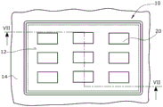
图1在俯视图中示出了可向下压的、弹性支承的操纵元件,该操纵元件在此实施例中具有九个操纵或操作/操纵区;FIG. 1 shows, in a plan view, a push-down, elastically mounted actuating element, which in this exemplary embodiment has nine actuating or actuating/actuating areas;
图2在透视图中示出了按图1的操纵元件的底侧;FIG. 2 shows the bottom side of the actuating element according to FIG. 1 in a perspective view;
图3至6在按图2的箭头III至VI的侧视图中示出了该操纵元件,其具有置于它下方的片簧-支承元件;FIGS. 3 to 6 show the actuating element in a side view according to the arrows III to VI of FIG. 2 with the leaf spring-bearing element placed below it;
图7在剖视图中示出了壳体,其具有处于原始状态中的、按图1至6所示的、弹性支承在此壳体中的操纵元件,即没有力传导到该操纵元件上;FIG. 7 shows a housing in a sectional view with the actuating element shown in FIGS. 1 to 6 in its original state, which is elastically supported in the housing, ie no force is transmitted to the actuating element;
图8示出了与图7类似的剖视图,但此时对该操纵元件进行手动操纵,因此其操纵被传感装置识别到;Fig. 8 shows a sectional view similar to that of Fig. 7, but this time the manipulation element is manually actuated, so that its manipulation is detected by the sensing device;
图9示出了与图7和8类似的剖视图,但是在激活执行器之后,以使操纵元件沿下压方向进一步运动,当作操纵元件的触觉/触知反馈。Figure 9 shows a cross-sectional view similar to Figures 7 and 8, but after activating the actuator to further move the manipulation element in the depression direction as tactile/tactile feedback for the manipulation element.
图10在与图1的俯视图类似的下视图中示出了操纵元件,但其具有以备选方式构成的片簧-支承元件;以及FIG. 10 shows the actuating element in a lower view similar to the top view of FIG. 1 , but with an alternatively configured leaf spring-bearing element; and
图11至14在按图10的箭头XI至XIV的方向的侧视图中示出了操纵元件,其具有置于底侧上的片簧-支承元件。FIGS. 11 to 14 show the actuating element in side view in the direction of the arrows XI to XIV of FIG. 10 with a leaf spring bearing element placed on the underside.
附图标记说明Description of reference numerals
10 操纵元件10 Control elements
12 操纵元件的操作表面12 Operating surfaces of the operating elements
14 壳体14 Housing
16 止动装置16 Stopper
18 用于操纵元件的支承装置18 Supports for operating elements
18' 用于操纵元件的支承装置18' Support for operating elements
20 操作表面上的标志区20 Marking area on the operating surface
22 操纵元件的底侧22 Bottom side of the operating element
24 角形片簧副24 angle leaf spring pair
26 角形片簧副26 angle leaf spring pair
28 操纵元件的角部区域28 Corner area of the manipulating element
30 操纵元件的角部区域30 Corner area of the manipulating element
32 角形片簧32 angle leaf spring
34 角形片簧34 angle leaf spring
36 角形片簧的边36 angled leaf spring sides
38 角形片簧的边38 angled leaf spring sides
40 (角形)片簧副的间距元件Spacing element for 40 (angle) leaf spring pair
42 (角形)片簧副的间距元件42 Spacing elements for (angle) leaf spring pair
44 片簧副在操作元件上的固定44 Fixing the leaf spring pair on the operating element
46 边的端部46 side end
48 (角形)片簧副的间距元件48 (Angle) Spacing Elements for Leaf Spring Pairs
50 片簧副与止动装置的连接50 Connection of leaf spring pair to stop
52 片簧副与止动装置的连接52 Connection between leaf spring pair and stopper
54 操作单元54 Operating unit
56 力或路程传感器56 Force or distance sensors
58 执行器58 Actuators
60 评估和操控单元60 Evaluation and control unit
62 导力点62 guide points
64 片簧副64 leaf spring pair
66 片簧副66 leaf spring pair
68 操纵元件的边缘区域68 The edge area of the manipulating element
70 操纵元件的边缘区域70 Manipulating the edge area of the element
72 操纵元件的边缘区域72 Edge area of the manipulating element
74 操纵元件的边缘区域74 Edge area of control element
具体实施方式Detailed ways
在图1至6示出了操纵元件10的结构和弹性支承,该操纵元件具有操作表面,该操作表面在该操纵元件10向下压时维持其定向,即该操作表面是被平行地推移。如图7所示,该操纵元件10装在壳体14的内部,该壳体包括止动装置16(其形式是电路板),该操纵元件10借助支承装置18以弹性的且可向下压的方式支承在此止动装置上。1 to 6 show the structure and elastic support of the
按照图1,该操作表面12具有多个(在此实施例中是九个)操作或操纵区20。在操纵元件10的背向操作表面12的底侧22上设置有支承装置18,其弹性地将操纵元件10与止动装置16连接起来。为实现此目的,支承装置18在按图1至9的实施例中具有两个角形片簧副24、26,它们设置在操纵元件10的底侧22的两相对而置的角部区域28、30中。每个角形片簧副24、26具有两个在此实施例中呈直角的片簧32、34,它们分别具有两个边36、38。在各个分别平行设置的边的自由端部上设置有间距元件40、42,该间距元件保持了各个边端部的间距,并且还与操纵元件10的下侧22相连。According to FIG. 1 , the operating
为此,间隔元件40、42分别在这些边36、38旁边的区域中延长越过各上方的角形片簧34,因此产生了偏差。For this purpose, the
在这些角部区域中或在角形片簧32、34的三角形边36、38的连接端部46上,同样设置有另一间距元件48。在图2的50、52中,在这些角部区域28、30中(即在连接端部46的区域中)的角形片簧副支承在止动装置16上。In these corner regions or on the connecting ends 46 of the
在图3至6的侧视图中清楚地示出了该角形片簧副24、26在操纵元件10的底侧22上的连接以及在止动装置16上的支承。The connection of the angled leaf spring pairs 24 , 26 on the
如果该操纵元件装在操作单元54中,在图7至9中示出了在操纵操纵元件10时的不同状况。操作单元54具有壳体14、止动装置16以及支承装置18。此外,该操作单元还在此实施例中设置有两个间距或力传感器56,它们借助在操纵操纵元件10时由该操纵元件经过的路径可识别到,在该操纵元件上施加了用来按期望地触发功能的最低操纵力。此外,操作单元54还具有执行器58,其在此实施例中构成为横向连杆-电磁铁。该传感器56和执行器58通过评估和操控单元60相互连接。If the actuating element is accommodated in the
图7示出了在操纵元件10还未操纵时的状况(静止位置)。在图8中示出了,例如在力传导箭头62的位置上,已将操纵力引导到操作表面12上。在维持操作表面的定向的情况下,即在平行移动操作表面12的情况下,将该操纵元件朝下移动。这些角形片簧副(在此实施例中是四个角形片簧副64、66,它们成对地相互定向)用来维持操作表面12的定向,其中这两个相互平行定向的第一片簧副64横向于第二片簧副66。FIG. 7 shows the situation when the
在图10至14中示出了按图1至9的实施例的支承装置18的备选实施例。Alternative embodiments of the
在图10中用参考标记18‘标出了相应的支承装置。在图10至14中示出的元件相当于图1至9的实施例的元件(也就是说,在结构或功能上是相同的),它们用相同的参考标记表示。The corresponding support means are marked with reference numeral 18' in FIG. 10 . Elements shown in Figures 10 to 14 are equivalent to elements of the embodiment of Figures 1 to 9 (that is, structurally or functionally identical) and are denoted by the same reference numerals.
在按图10至14的实施例中存在着四个相互分开构造和设置的片簧副64、66,它们分别具有两个片簧36或38。这四个片簧64、66在操纵元件10的四个边缘区域68、70、72、74上分散地设置在其底侧22上。在图10至14中的50再次示出了,这些片簧副是在何处支承在止动装置16上。在这些附图中的44再次示出了,这些片簧副64、66在何处连接到操纵元件10的底侧22上。In the exemplary embodiment according to FIGS. 10 to 14 , there are four leaf spring pairs 64 , 66 , which are constructed and arranged separately from one another, each having two
Claims (9)
Applications Claiming Priority (3)
| Application Number | Priority Date | Filing Date | Title |
|---|---|---|---|
| DE102015220789 | 2015-10-23 | ||
| DE102015220789.7 | 2015-10-23 | ||
| PCT/EP2016/075565 WO2017068189A1 (en) | 2015-10-23 | 2016-10-24 | Control unit for a vehicle component, in particular for a heating, ventilation and/or air conditioning system |
Publications (2)
| Publication Number | Publication Date |
|---|---|
| CN108351663A CN108351663A (en) | 2018-07-31 |
| CN108351663B true CN108351663B (en) | 2020-08-28 |
Family
ID=57200009
Family Applications (1)
| Application Number | Title | Priority Date | Filing Date |
|---|---|---|---|
| CN201680063339.3A Active CN108351663B (en) | 2015-10-23 | 2016-10-24 | Operating units for vehicle components, in particular heating, ventilation and/or air conditioning systems |
Country Status (7)
| Country | Link |
|---|---|
| US (1) | US20180329444A1 (en) |
| EP (1) | EP3365745B1 (en) |
| JP (1) | JP6839183B2 (en) |
| KR (1) | KR102704409B1 (en) |
| CN (1) | CN108351663B (en) |
| ES (1) | ES2819872T3 (en) |
| WO (1) | WO2017068189A1 (en) |
Families Citing this family (2)
| Publication number | Priority date | Publication date | Assignee | Title |
|---|---|---|---|---|
| DE102022100993B4 (en) | 2022-01-17 | 2023-10-26 | Behr-Hella Thermocontrol Gmbh | Control unit for a vehicle, in particular for one or more vehicle components |
| WO2025176505A1 (en) | 2024-02-19 | 2025-08-28 | BHTC GmbH | Operating unit for a vehicle, in particular for operating one or more vehicle components |
Family Cites Families (22)
| Publication number | Priority date | Publication date | Assignee | Title |
|---|---|---|---|---|
| US1037729A (en) * | 1911-08-26 | 1912-09-03 | Robert J Collins | Spring. |
| US2989063A (en) * | 1958-06-18 | 1961-06-20 | Bailey Meter Co | Pneumatic transmitter |
| DE2345990A1 (en) * | 1970-04-15 | 1975-04-03 | Raoul Dipl Ing Joern | SPRING ELEMENT, IN PARTICULAR FOR THE ELASTIC MOUNTING OF MOTORS |
| DE3616669A1 (en) | 1986-05-16 | 1987-11-19 | Jung Albrecht Fa | ACTUATING DEVICE FOR SWITCHING DEVICES |
| DE3711789A1 (en) | 1987-04-08 | 1988-10-27 | Kostal Leopold Gmbh & Co Kg | Push-button switch |
| DE9010425U1 (en) * | 1990-07-11 | 1990-10-11 | Siemens AG, 8000 München | Device for transmitting a linear movement using a probe element |
| JPH09147663A (en) * | 1995-11-21 | 1997-06-06 | Yazaki Corp | Touch panel switch |
| DE19757928C2 (en) | 1997-12-24 | 1999-10-28 | Hella Kg Hueck & Co | Operating unit for a vehicle component, in particular for an air conditioning system |
| FR2813931B1 (en) * | 2000-09-08 | 2006-10-20 | Mannesmann Sachs Ag | TANGENTIAL BLADE SPRING DEVICE FOR COUPLING A PRESSURE PLATE TO A CARTER |
| DE10126776B4 (en) * | 2001-06-01 | 2013-07-11 | Zf Friedrichshafen Ag | Pressure plate assembly with contact force reinforcement |
| US8139035B2 (en) * | 2006-06-21 | 2012-03-20 | Nokia Corporation | Touch sensitive keypad with tactile feedback |
| DE102008019124B4 (en) * | 2008-04-16 | 2010-04-08 | E-LEAD ELECTRONIC CO., LTD., Shengang Shiang | Keyboard with multi-axis balancing touch keys |
| JP4633166B2 (en) * | 2008-12-22 | 2011-02-16 | 京セラ株式会社 | Input device and control method of input device |
| JP5270384B2 (en) * | 2009-01-15 | 2013-08-21 | 株式会社ミツトヨ | Linear guide mechanism and measuring device |
| JP5026486B2 (en) * | 2009-09-29 | 2012-09-12 | 日本写真印刷株式会社 | Mounting structure of touch input device with pressure sensitive sensor |
| FR2958420B1 (en) * | 2010-03-31 | 2012-12-07 | Valeo Systemes Thermiques | MAN / MACHINE INTERFACE, IN PARTICULAR FOR MOTOR VEHICLE |
| US20110291947A1 (en) * | 2010-05-27 | 2011-12-01 | Nigel Patrick Pemberton-Pigott | Touch-Sensitive Display |
| DE102011082143A1 (en) * | 2011-09-05 | 2013-03-07 | Continental Automotive Gmbh | operating device |
| DE102014007988A1 (en) * | 2013-06-13 | 2014-12-18 | Marquardt Gmbh | Shift operating arrangement |
| JP5904174B2 (en) * | 2013-08-22 | 2016-04-13 | Smk株式会社 | Touch panel support structure |
| KR102373994B1 (en) * | 2014-07-22 | 2022-03-11 | 베르-헬라 테르모콘트롤 게엠베하 | Operating unit for an electrical apparatus |
| JP6055041B1 (en) * | 2015-07-16 | 2016-12-27 | レノボ・シンガポール・プライベート・リミテッド | Electronics |
-
2016
- 2016-10-24 CN CN201680063339.3A patent/CN108351663B/en active Active
- 2016-10-24 JP JP2018521118A patent/JP6839183B2/en active Active
- 2016-10-24 KR KR1020187013761A patent/KR102704409B1/en active Active
- 2016-10-24 US US15/770,315 patent/US20180329444A1/en not_active Abandoned
- 2016-10-24 ES ES16785479T patent/ES2819872T3/en active Active
- 2016-10-24 EP EP16785479.3A patent/EP3365745B1/en active Active
- 2016-10-24 WO PCT/EP2016/075565 patent/WO2017068189A1/en not_active Ceased
Also Published As
| Publication number | Publication date |
|---|---|
| CN108351663A (en) | 2018-07-31 |
| EP3365745B1 (en) | 2020-06-24 |
| KR102704409B1 (en) | 2024-09-06 |
| EP3365745A1 (en) | 2018-08-29 |
| ES2819872T3 (en) | 2021-04-19 |
| KR20180087250A (en) | 2018-08-01 |
| US20180329444A1 (en) | 2018-11-15 |
| WO2017068189A1 (en) | 2017-04-27 |
| JP6839183B2 (en) | 2021-03-03 |
| JP2018535138A (en) | 2018-11-29 |
Similar Documents
| Publication | Publication Date | Title |
|---|---|---|
| JP6543328B2 (en) | Control unit for electrical equipment | |
| JP6301355B2 (en) | Operating device for vehicle parts | |
| US10429186B2 (en) | Microelectromechanical device with motion limiters | |
| US9793076B2 (en) | Switching operating arrangement | |
| CN108351663B (en) | Operating units for vehicle components, in particular heating, ventilation and/or air conditioning systems | |
| US20120217144A1 (en) | Switch device | |
| US20090189024A1 (en) | Device for Remotely Controlling Aircraft Control Surfaces | |
| US9343249B2 (en) | Pressure and rotationally actuated control element for a motor vehicle | |
| US11061427B2 (en) | Operating device | |
| CN118613381A (en) | Input device for a motor vehicle | |
| CN104781637B (en) | Capacitive sensors for detecting the relative motion of two adjacent objects | |
| CN109863571B (en) | Buttons and Electronic Devices | |
| JP2007232055A (en) | Shift operation position detection device | |
| JP2018013990A5 (en) | ||
| JP6652875B2 (en) | Push-pull switch device | |
| JP2006331917A (en) | Input device | |
| EP3279761A1 (en) | Multifunctional control device | |
| JP5819258B2 (en) | Push switch | |
| JP2020064725A (en) | Load receiving member, load receiving unit, and operation input device | |
| JP6204232B2 (en) | Input device |
Legal Events
| Date | Code | Title | Description |
|---|---|---|---|
| PB01 | Publication | ||
| PB01 | Publication | ||
| SE01 | Entry into force of request for substantive examination | ||
| SE01 | Entry into force of request for substantive examination | ||
| GR01 | Patent grant | ||
| GR01 | Patent grant |