EP2753907B1 - Lonisations - vakuummesszelle - Google Patents
Lonisations - vakuummesszelle Download PDFInfo
- Publication number
- EP2753907B1 EP2753907B1 EP12748149.7A EP12748149A EP2753907B1 EP 2753907 B1 EP2753907 B1 EP 2753907B1 EP 12748149 A EP12748149 A EP 12748149A EP 2753907 B1 EP2753907 B1 EP 2753907B1
- Authority
- EP
- European Patent Office
- Prior art keywords
- electrode
- yoke
- permanent magnet
- cell according
- measurement cell
- Prior art date
- Legal status (The legal status is an assumption and is not a legal conclusion. Google has not performed a legal analysis and makes no representation as to the accuracy of the status listed.)
- Active
Links
- 230000005291 magnetic effect Effects 0.000 claims description 47
- 238000005259 measurement Methods 0.000 claims description 28
- 230000005294 ferromagnetic effect Effects 0.000 claims description 5
- 230000000149 penetrating effect Effects 0.000 claims description 4
- 230000005415 magnetization Effects 0.000 description 20
- 239000000696 magnetic material Substances 0.000 description 12
- 230000004907 flux Effects 0.000 description 7
- 239000000463 material Substances 0.000 description 6
- 230000005292 diamagnetic effect Effects 0.000 description 4
- 241001295925 Gegenes Species 0.000 description 3
- 239000002131 composite material Substances 0.000 description 3
- 230000005684 electric field Effects 0.000 description 3
- 238000000034 method Methods 0.000 description 3
- 239000003302 ferromagnetic material Substances 0.000 description 2
- 238000004519 manufacturing process Methods 0.000 description 2
- 229910052779 Neodymium Inorganic materials 0.000 description 1
- 229910052772 Samarium Inorganic materials 0.000 description 1
- 238000005452 bending Methods 0.000 description 1
- 230000002146 bilateral effect Effects 0.000 description 1
- 229910010293 ceramic material Inorganic materials 0.000 description 1
- 239000002800 charge carrier Substances 0.000 description 1
- 238000010276 construction Methods 0.000 description 1
- 230000001419 dependent effect Effects 0.000 description 1
- 230000001627 detrimental effect Effects 0.000 description 1
- 230000000694 effects Effects 0.000 description 1
- 238000010304 firing Methods 0.000 description 1
- 230000005358 geomagnetic field Effects 0.000 description 1
- 229910052751 metal Inorganic materials 0.000 description 1
- 239000002184 metal Substances 0.000 description 1
- 239000007769 metal material Substances 0.000 description 1
- QEFYFXOXNSNQGX-UHFFFAOYSA-N neodymium atom Chemical compound [Nd] QEFYFXOXNSNQGX-UHFFFAOYSA-N 0.000 description 1
- VIKNJXKGJWUCNN-XGXHKTLJSA-N norethisterone Chemical compound O=C1CC[C@@H]2[C@H]3CC[C@](C)([C@](CC4)(O)C#C)[C@@H]4[C@@H]3CCC2=C1 VIKNJXKGJWUCNN-XGXHKTLJSA-N 0.000 description 1
- 239000002245 particle Substances 0.000 description 1
- 230000010287 polarization Effects 0.000 description 1
- KZUNJOHGWZRPMI-UHFFFAOYSA-N samarium atom Chemical compound [Sm] KZUNJOHGWZRPMI-UHFFFAOYSA-N 0.000 description 1
- 238000007789 sealing Methods 0.000 description 1
- 229910000859 α-Fe Inorganic materials 0.000 description 1
Images


Classifications
-
- G—PHYSICS
- G01—MEASURING; TESTING
- G01L—MEASURING FORCE, STRESS, TORQUE, WORK, MECHANICAL POWER, MECHANICAL EFFICIENCY, OR FLUID PRESSURE
- G01L21/00—Vacuum gauges
- G01L21/30—Vacuum gauges by making use of ionisation effects
-
- G—PHYSICS
- G01—MEASURING; TESTING
- G01L—MEASURING FORCE, STRESS, TORQUE, WORK, MECHANICAL POWER, MECHANICAL EFFICIENCY, OR FLUID PRESSURE
- G01L21/00—Vacuum gauges
- G01L21/30—Vacuum gauges by making use of ionisation effects
- G01L21/34—Vacuum gauges by making use of ionisation effects using electric discharge tubes with cold cathodes
-
- H—ELECTRICITY
- H01—ELECTRIC ELEMENTS
- H01J—ELECTRIC DISCHARGE TUBES OR DISCHARGE LAMPS
- H01J41/00—Discharge tubes for measuring pressure of introduced gas or for detecting presence of gas; Discharge tubes for evacuation by diffusion of ions
- H01J41/02—Discharge tubes for measuring pressure of introduced gas or for detecting presence of gas
- H01J41/06—Discharge tubes for measuring pressure of introduced gas or for detecting presence of gas with ionisation by means of cold cathodes
Definitions
- the invention relates to an ionization vacuum measuring cell according to the preamble of claim 1.
- gas pressure measuring cells for the vacuum measurement, which are based on the principle of a gas discharge with a cold cathode.
- Such measuring cells are also referred to as cold cathode ionization gauge or Penning cells.
- a sufficiently high DC voltage is applied between two electrodes (anode, cathode), whereby a gas discharge can be ignited and maintained.
- the discharge current is then a measure of the pressure to be measured.
- a magnetic field formed in the region of the discharge gap carries the electrons on their way from the negative electrode (cathode) to the positive electrode (anode) in spiral-like paths, thereby extending the trajectory of the electrons. This increases the probability of hit with the gas particles and improves the degree of ionization. This ensures that the discharge can burn over wide pressure ranges and behaves stable and reproducible.
- the most widely used design is that of the inverted magnetron, since it generally gives a more stable measurement signal than the Penning cell in high vacuum, firing discharge more easily at low pressures, and the lower measurement range for lower pressures up to 10 -11 mbar can be brought.
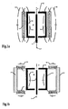
- Variant (A) is the classic variant, with the advantage that such annular magnets 1 with axial magnetization are simple and inexpensive to manufacture. In combination with suitable baffles made of soft magnetic material can thus achieve homogeneous Nutzfeldlinien 14 and this magnetic flux densities in the ionization of the meter.
- the cathode 3 is, as already mentioned, cylindrical and encloses the discharge space or a measuring chamber 20 a. In the axis of the cylindrical cathode 3, the anode 4 is arranged. The whole is enclosed by the annular permanent magnet 1 with axial polarity alignment to the axis 7. In the FIG. 1a the north pole is denoted by N and the south pole by S. The polarities can also be reversed within the arrangement.
- the cylindrical cathode directed towards the axis 7, can have further electrode surfaces which are at the same potential and additionally reflect the electrons back into the discharge space.
- the discharge space has at least one opening which communicates with the outside to be measured with the vacuum space P.
- a measuring cell is formed there as a releasable flange connection.
- the variant (B) has two radially magnetized spaced from each other in the axial direction rings, which are connected via an annular yoke 2 made of soft magnetic material for the conclusion of the magnetic circuit.
- variant (B) has smaller stray fields 15 towards the outside, in particular in the radial direction. A portion of the generated magnetic field 15 closes outside the ionization space and forms a stray field 15 and this contributes nothing to the payload field 14 at.
- Such external stray fields 15 are disadvantageous because these devices and processes located there can interfere.
- the variant (B) with the smaller stray field 15 against the outside is consequently more advantageous in this regard. However, this also means that less permanent magnet material has to be used for the same flux densities in the ionization space.
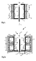
- Variant (C) was from Drubetsky & Taylor, US 5,568,053 , proposed. It results in a field that changes the direction with respect to the cylinder axis at the height between the two magnetic rings. On the cylinder axis, the field is even zero in this area, because the flux densities of the two magnets cancel each other out.
- the advantage of this arrangement is a smaller stray field compared to variant (A) for given flow density requirements in the measuring chamber.
- the stray field is still appreciably present and can interfere, especially if a strong field of use is to be generated in the measuring chamber, then the external stray field becomes correspondingly stronger and continues to enter the outside area.
- variant (A) A disadvantage of variant (A) are the relatively strong flux densities, which extend to outside the ionization chamber and even the entire measuring cell arrangement and occur there as stray fields 15, as shown in FIG. 1 a is shown. This has detrimental effects on nearby devices and on processes that may occur in the nature of typical use in the immediate vicinity of the measuring cell, particularly in processes operated with charge carriers or ionized gas.
- variant (B) reduces such stray fields 15 by forming a magnetic closure outside the ionization chamber, between the two ring magnets 1, by arranging a guide plate 2 or a yoke made of soft magnetic material. However, significantly disturbing external stray fields 15 due to the magnetic shunt between the poles N, S in each of the two ring magnets 1 continue to form, as shown in FIGS FIG. 2b is shown.
- the gas discharge is small due to the small, no longer perpendicular to the electric field axis magnetic flux density in the center at the height between the two magnetic rings and therefore remains a part of the measuring cell volume unused.
- a non-negligible disturbing Stray field 15 as in the Figure 1c is shown and which acts approximately similar to that previously to variant (A), according to the FIG. 1a , has been explained.
- the present invention has the object of providing a magnetic field configuration for a cold cathode ionization vacuum measuring cell which includes a magnetron arrangement and in which disturbing stray magnetic fields outside the measuring cell are substantially reduced, or even substantially avoided altogether.
- the measuring cell should also be able to detect a large pressure range to be measured and work reliably and reproducibly. Furthermore, this should be compact and economical to produce.
- the arrangement with the magnet system forms a magnetron.
- the first, outer electrode can be operated as an anode, wherein the second, inner electrode is operated as a cathode.
- the much preferred arrangement forms an inverted magnetron.
- the outer, first electrode is operated as a cathode and the coaxial inner electrode is operated as an anode.
- the discharge efficiency is much better and more stable.
- the preferably arranged in the center anode is preferably formed rod-shaped.
- the magnet system thus always has soft magnetic material in the outer region.
- the bilateral magnetic closure between the poles passes over the soft magnetic material. This avoids that the magnet system generates a disturbing stray field towards the outside or at least minimizes such a stray field.
- at least two annular, tunnel-like, inwardly directed magnetic field configurations are formed over the surface of the first electrode, each having an axial component.
- the field lines go from the inner pole of the at least one permanent magnet inwards and penetrate the first electrode, which close on both sides of the magnet on the poles of the soft magnetic yoke, in turn, by penetrating the first electrode.
- the field lines at the height of the magnet within the ionization chamber change direction, whereby the two adjacent tunnel-like fields, in their polarity, run in opposite directions. This results in at least two adjacent annular toroidal discharges over the first electrode.
- the electrons rotating therein oscillate laterally along the field lines as viewed in cross-section and rotate in a circle within the rings in the opposite direction and cause a high degree of ionization, which is typical of the magnetron effect in a well-designed magnetron arrangement, due to the extended residence time. of the present kind.
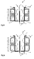
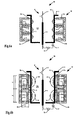
- a first embodiment of an ionization vacuum measuring cell 30 with a magnetron magnetic field arrangement 19 according to the invention is shown for example in US Pat FIG. 2a shown schematically and in cross section.
- a housing 10 has a measuring port 8 and this can be connected to the vacuum to be measured, whereby the housing 10 is evacuated accordingly.
- the connection between this housing 10 and the container with the vacuum to be measured can be done for example via a sealing flange.
- the vacuum measuring cell 30 comprises the housing 10, with two electrodes 3, 4 and a magnet system 19, wherein in the present embodiment, the housing 10 enclose them.
- the magnet system 19 includes a Permanent magnet ring 1 and a yoke 2 made of soft magnetic material.
- the soft magnetic material may include both metallic materials (ferromagnetic), as well as ceramic materials such as ferrites.
- the first and a second electrodes 3, 4 are arranged substantially coaxially and spaced from one another and have a common axis 7.
- the first electrode 3 forms the outer electrode and has a substantially cylindrical surface.
- the second electrode 4 may also be cylindrical, but is advantageously designed rod-shaped and is located advantageously in the center, lying in the axis 7.
- Both electrodes can be powered electrically via vacuum-tight, electrical feedthroughs 12, 12 'on the housing 10.
- a voltage source 16 is connected to the electrodes 2, 3.
- Current measuring means 17 are used to evaluate a discharge current, the discharge, which is formed between the electrodes 3, 4. This discharge current corresponds to a function of the vacuum pressure to be measured and is electronically evaluated and supplied for further use.
- At least one permanent magnet ring 1 encloses the coaxial arrangement of the electrodes 3, 4 with the magnetization direction 13 aligned essentially radially with respect to the axis.
- This permanent magnet ring 1 is further surrounded by a yoke 2, which consists of soft magnetic material for guiding the magnetic field.
- the yoke 2 is guided in the axial direction on both sides of the permanent magnet ring 1 away and guided by a predetermined distance d from the permanent magnet ring 1 on both sides in the radial direction to the axis 7 and the first electrode 3. This creates in cross-section a kind of U-shaped yoke, which forms on both sides and spaced from the permanent magnet ring 1 poles 9a and 9b.
- the first electrode 3 is the outer electrode of the coaxial arrangement of the electrodes 3, 4. At least part of the field lines of the permanent magnet ring 1, the Nutzfeldlinien 14 which are decisive for the discharge, thus close over the pole of the permanent magnet ring 1 and the respective Pol 9a, 9b of the yoke 2 within the Measuring chamber 20, the first electrode 3 penetrating, wherein preferably an annular tunnel-like magnetic field 14 is formed over the first electrode 3 within the measuring chamber 20.
- the arrangement according to the FIG. 1a are each a tunnel-like magnetic field 14 formed on both sides of the permanent magnet ring 1, so two annular or toroidal magnetic fields 14 with opposite polarity of the field line course.
- the outer first electrode 3 is preferably operated as a cathode and the inner second electrode 4 as an anode.
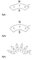
- the permanent magnet ring 1 is magnetized in the radial direction and preferably contains magnetic material of the group of rare earths, such as neodymium, samarium, etc.
- the magnetization takes place in the indicated arrow direction, in the case of the segment of FIG. 5a in a uniform direction or in the case of the segment of FIG. 5b in the radial direction.
- FIG. 5c be individual, for example, rectangular magnets lined up in a ring.
- the length h is then preferably longer than wide at the individual piece.
- the thickness of the magnetic ring 1 is preferably not greater than the width h.
- the shape of the U-shaped yoke 2 is formed at least partially angled in the sectional plane in which the axis 7, so that in the axial direction at a distance d on both sides of the permanent magnet ring 1, the resulting legs of the yoke 2 in the radial direction to the axis 7 of the measuring cell 30th point and there on both sides each form an annular pole 9a, 9b, which is guided against the first electrode 3 out.
- the bend is formed at right angles, as in the FIGS. 2a to 2d . 3 . 4 and 6 is shown.
- the poles 9a, 9b of the yoke and the inner pole of the permanent magnet ring are preferably equidistant from the axis 7.
- the poles 9a, 9b of the yoke are arranged such that the magnetic field 14 passes through the first electrode 3 there.
- the useful magnetic field 14 thus leads away from the pole of the permanent magnet ring 1 through the first electrode 3 and closes arcuately within the measuring chamber 20 via the two poles 9a, 9b of the yoke 2, where it is again passed through the first electrode 3 therethrough.
- the passage of the magnetic field through the first electrode 3 leads to a high discharge efficiency.
- one or both poles 9a, 9b of the yoke 2 may also be arranged such that the field lines 14 pass only partially or not at all through the first electrode 3, as shown for example in FIG FIG. 2b in the upper area for the one pole 9a is shown.
- the first electrode 3 is shown angled towards the axis, so that also there the field lines 14 again pass through the first electrode 3.
- the first electrode 3 forms a kind of closed cylinder which has only one opening 8 for the supply of the sample gas P and possibly means for supporting the second electrode within this cylinder with an electrical feedthrough for feeding the second electrode.
- FIG. 2a the elements of the measuring cell 30, the magnet system 19 and the two electrodes 3, 4 are enclosed by a vacuum-tight housing 10.
- This housing 10 has an opening 8 and a connection 11, preferably designed as a flange, with which the measuring cell 30 communicating with the vacuum volume to be measured, sealingly connected.
- This connection is advantageously designed as a detachable connection, whereby the measuring cell 30 can be treated as a component easily replaceable.
- FIG. 2b Another possible embodiment of the measuring cell 30 with the housing 10 is in the FIG. 2b shown.
- the yoke 2 of the magnet system is simultaneously formed as a vacuum-tight housing 10 with connection means 11 arranged thereon.
- the yoke 2 may also be part of the housing 10 only.
- the housing 10 may be made partly of soft magnetic or ferromagnetic material and partly of non-magnetic material, such as inox.
- the housing 10 may be disposed between the first electrode 3 and the magnet system 19, such that the magnet system comes to rest outside of the vacuum enclosing housing 10. This has the advantage that the materials of the magnet system 19 can not contaminate or contaminate the space of the measuring chamber 20, as a result of which the measurement result could be unfavorably influenced.
- the first electrode 3 can also be formed as a vacuum-tight housing 10 at the same time. This also enables the magnetic system 19 to be vacuum-separated from the measuring chamber 20 and also a compact, simple design of the measuring cell 30.
- the permanent magnet ring 1 can be arranged asymmetrically within the yoke 2 between its legs with the two poles 9a, 9b in the axial direction or even displaceable, as shown in the FIG. 4 is shown with the arrows 18 indicating the direction of movement.
- the permanent magnet ring 1 is arranged centrally relative to the poles 9 a, 9 b of the yoke 2, so that the poles 9 a, 9 b of the yoke 2 are arranged symmetrically with respect to the permanent magnet ring 1.
- the magnetic field which is directed inwards from the poles, can be influenced by additional conducting means to further optimize the discharge.
- additional conducting means For example, directed in the radial direction towards the axis 7, in the region of the inner pole of the permanent magnet ring (1), ferromagnetic guide means 6 are arranged, as shown in the FIGS. 3 and 4 is shown. Also, for example, directed in the radial direction against the axis 7, in the region of at least one of the inner poles 9a, 9b of the yoke 2, ferromagnetic guide means 5a, 5b are arranged.
- Such guide means can be made as sheet metal parts and / or plates made of soft magnetic or ferromagnetic material, which are for example disc-shaped. As required, openings are provided therein to pass the second electrode 4 and / or to facilitate gas exchange.
- FIG. 6a Another embodiment of the magnet system 19 is shown in FIG. 6a shown, in which two permanent magnet rings 1, axially spaced from each other and opposite to each other, are disposed within the yoke 2.
- This arrangement produces a particularly strong annular magnetron field between the two poles of the permanent magnet rings 1 on the first electrode 3 within the measuring chamber 20.
- On both sides then run ever another annular field, which are completed by the two poles 9a, 9b of the yoke 2 and As a result, stray fields passing outwards are avoided.
- FIG. 6b Another embodiment of the magnet system 19 is in the FIG. 6b shown.
- a further ring magnet 21a, 21b is arranged each which is magnetized in the axial direction and which are arranged in the area against the axis 7 within the magnet system.
- the thickness of the magnetic ring 21 in the radial direction is at most half the width h of the permanent magnet ring 1.
- the measuring cell 30, for example, operated at a voltage of 3.3 kV between the two electrodes 3, 4, ie between the cathode 3 and anode 4.
- the preferred range for the operation of the measuring cell 30 is between 2.0 kV and 4.5 kV.
- the flux density on the cylinder axis, measured within the measuring chamber in the axial direction, is in the range of 10 mT (milli Tesla) to 300 mT, preferably in the range of 60 to 130 mT.
- these lowest achievable limit values are at most about 0.01 mT corresponding to 0.1 Gauss, which is approximately the order of magnitude of the geomagnetic field measured at the earth's surface.
Landscapes
- Physics & Mathematics (AREA)
- General Physics & Mathematics (AREA)
- Measuring Fluid Pressure (AREA)
Applications Claiming Priority (2)
| Application Number | Priority Date | Filing Date | Title |
|---|---|---|---|
| CH01483/11A CH705474A1 (de) | 2011-09-08 | 2011-09-08 | Ionisations - Vakuummesszelle. |
| PCT/CH2012/000177 WO2013033851A1 (de) | 2011-09-08 | 2012-08-02 | Lonisations - vakuummesszelle |
Publications (2)
| Publication Number | Publication Date |
|---|---|
| EP2753907A1 EP2753907A1 (de) | 2014-07-16 |
| EP2753907B1 true EP2753907B1 (de) | 2015-10-21 |
Family
ID=46690347
Family Applications (1)
| Application Number | Title | Priority Date | Filing Date |
|---|---|---|---|
| EP12748149.7A Active EP2753907B1 (de) | 2011-09-08 | 2012-08-02 | Lonisations - vakuummesszelle |
Country Status (6)
| Country | Link |
|---|---|
| US (1) | US9116065B2 (zh) |
| EP (1) | EP2753907B1 (zh) |
| JP (1) | JP6019121B2 (zh) |
| CN (1) | CN103959032B (zh) |
| CH (1) | CH705474A1 (zh) |
| WO (1) | WO2013033851A1 (zh) |
Families Citing this family (10)
| Publication number | Priority date | Publication date | Assignee | Title |
|---|---|---|---|---|
| CH707685A1 (de) * | 2013-03-06 | 2014-09-15 | Inficon Gmbh | Ionisations-Vakuummesszelle mit Abschirmvorrichtung. |
| TW201634219A (zh) * | 2015-01-15 | 2016-10-01 | Mks儀器公司 | 聚合物複合物真空組件 |
| US11164731B2 (en) * | 2015-09-23 | 2021-11-02 | Inficon ag | Ionization vacuum measuring cell |
| EP4016035A1 (en) * | 2017-03-13 | 2022-06-22 | Canon Anelva Corporation | Cold cathode ionization gauge and cold cathode ionization gauge cartridge |
| EP3702760A4 (en) * | 2017-10-24 | 2021-10-13 | Marunaka Co., Ltd. | GAS ANALYZER |
| US10928265B2 (en) | 2018-05-29 | 2021-02-23 | Mks Instruments, Inc. | Gas analysis with an inverted magnetron source |
| CN114286930B (zh) * | 2019-09-13 | 2022-12-20 | 佳能安内华股份有限公司 | 电离真空计和匣盒 |
| CN110780167B (zh) * | 2019-11-12 | 2021-08-17 | 西南交通大学 | 一种桶式复合绝缘材料绝缘性能检测装置 |
| US10948456B1 (en) | 2019-11-27 | 2021-03-16 | Mks Instruments, Inc. | Gas analyzer system with ion source |
| CN111141448B (zh) * | 2020-01-08 | 2021-10-19 | 北京大学(天津滨海)新一代信息技术研究院 | 一种片上平面式微型电离真空传感器和制造方法 |
Family Cites Families (8)
| Publication number | Priority date | Publication date | Assignee | Title |
|---|---|---|---|---|
| GB9302587D0 (en) * | 1993-02-10 | 1993-03-24 | Boc Group The | Magnitc structures |
| ATE168467T1 (de) * | 1993-04-28 | 1998-08-15 | Fredericks Co | Ionisationswandler mit sich gegenuberliegenden magneten |
| JP3325982B2 (ja) * | 1993-12-27 | 2002-09-17 | 株式会社東芝 | 磁界界浸型電子銃 |
| JP2001332209A (ja) * | 2000-03-13 | 2001-11-30 | Ulvac Japan Ltd | スパッタイオンポンプ |
| US7084573B2 (en) * | 2004-03-05 | 2006-08-01 | Tokyo Electron Limited | Magnetically enhanced capacitive plasma source for ionized physical vapor deposition |
| JP4905704B2 (ja) * | 2007-06-08 | 2012-03-28 | 株式会社アルバック | 点火補助具およびこれを備えた冷陰極電離真空計 |
| JP4992885B2 (ja) * | 2008-11-21 | 2012-08-08 | 日新イオン機器株式会社 | プラズマ発生装置 |
| CN102087949B (zh) * | 2010-12-31 | 2012-11-21 | 清华大学 | 真空规管 |
-
2011
- 2011-09-08 CH CH01483/11A patent/CH705474A1/de not_active Application Discontinuation
-
2012
- 2012-08-02 US US14/237,007 patent/US9116065B2/en active Active
- 2012-08-02 CN CN201280043956.9A patent/CN103959032B/zh active Active
- 2012-08-02 JP JP2014528815A patent/JP6019121B2/ja active Active
- 2012-08-02 EP EP12748149.7A patent/EP2753907B1/de active Active
- 2012-08-02 WO PCT/CH2012/000177 patent/WO2013033851A1/de active Application Filing
Also Published As
| Publication number | Publication date |
|---|---|
| CN103959032A (zh) | 2014-07-30 |
| US20140176150A1 (en) | 2014-06-26 |
| JP2014525590A (ja) | 2014-09-29 |
| US9116065B2 (en) | 2015-08-25 |
| JP6019121B2 (ja) | 2016-11-02 |
| WO2013033851A1 (de) | 2013-03-14 |
| CH705474A1 (de) | 2013-03-15 |
| EP2753907A1 (de) | 2014-07-16 |
| CN103959032B (zh) | 2015-12-09 |
Similar Documents
| Publication | Publication Date | Title |
|---|---|---|
| EP2753907B1 (de) | Lonisations - vakuummesszelle | |
| CH707685A1 (de) | Ionisations-Vakuummesszelle mit Abschirmvorrichtung. | |
| DE60307609T2 (de) | Vorrichtung zur begrenzung eines plasmas in einem volumen | |
| EP1269020A2 (de) | Plasma-beschleuniger-anordnung | |
| DE2934408A1 (de) | Ionenquelle mit kaltkathode und damit ausgeruestetes massenspektrometer | |
| WO2010000316A1 (de) | Elektromotorischer lineargenerator | |
| EP0150389B1 (de) | Vorrichtung zum Messen des Innendrucks eines betriebsmässig eingebauten Vakuumschalters | |
| DE1123773B (de) | Magnetisches Fokussierungssystem zur gebuendelten Fuehrung des Elektronenstrahls einer Laufzeitroehre | |
| DE1441243A1 (zh) | ||
| DE112018007289B4 (de) | Multipol-linse, aberrationsverbesserer unter verwendung derselben und vorrichtung für einen strahl geladener teilchen | |
| EP2337059B1 (de) | Gasentladungslampe mit Außenelektrode | |
| EP0316523A2 (de) | Zerstäubungskatode nach dem Magnetronprinzip | |
| WO2001027964A2 (de) | Elektronenstossionenquelle | |
| EP0431233B1 (de) | Partialdruckmesszelle mit Kaltkathodenionenquelle für die Lecksuche in Vakuumsystemen | |
| DE3438987A1 (de) | Auger-elektronenspektrometer mit hoher aufloesung | |
| DE3538407A1 (de) | Ionen-zyklotron-resonanz-spektrometer | |
| EP0015391B1 (de) | Glimmentladungslampe zur qualitativen und quantitativen Spektralanalyse | |
| DE1238120B (de) | Ioneneinspritzvorrichtung fuer Geraete zur Erzeugung eines Hochtemperatur-Plasmas | |
| DE1194093B (de) | Mit Kathodenzerstaeubung arbeitende Ionen-Vakuumpumpe | |
| DE1281187B (de) | Elektronenstoss-Ionenquelle mit einer durch die Entladung selbst erregten Elektronenemission fuer elektrische Massenfilter | |
| DE102011010138B4 (de) | Kaltkathoden-Druckmessvorrichtung vom Penning-Typ | |
| DE1070850B (zh) | ||
| CH719946A2 (de) | Kammer für Ionisationsvakuummeter. | |
| DE1441243C (de) | Kreiszylindrische Elektronenrohre der Magnetronbauart | |
| DE2817310A1 (de) | Glimmentladungslampe zur qualitativen und quantitativen spektralanalyse |
Legal Events
| Date | Code | Title | Description |
|---|---|---|---|
| PUAI | Public reference made under article 153(3) epc to a published international application that has entered the european phase |
Free format text: ORIGINAL CODE: 0009012 |
|
| 17P | Request for examination filed |
Effective date: 20140207 |
|
| AK | Designated contracting states |
Kind code of ref document: A1 Designated state(s): AL AT BE BG CH CY CZ DE DK EE ES FI FR GB GR HR HU IE IS IT LI LT LU LV MC MK MT NL NO PL PT RO RS SE SI SK SM TR |
|
| DAX | Request for extension of the european patent (deleted) | ||
| RIC1 | Information provided on ipc code assigned before grant |
Ipc: G01L 21/30 20060101ALI20141216BHEP Ipc: H01J 41/06 20060101ALI20141216BHEP Ipc: G01L 21/34 20060101AFI20141216BHEP |
|
| GRAP | Despatch of communication of intention to grant a patent |
Free format text: ORIGINAL CODE: EPIDOSNIGR1 |
|
| INTG | Intention to grant announced |
Effective date: 20150520 |
|
| GRAS | Grant fee paid |
Free format text: ORIGINAL CODE: EPIDOSNIGR3 |
|
| GRAA | (expected) grant |
Free format text: ORIGINAL CODE: 0009210 |
|
| AK | Designated contracting states |
Kind code of ref document: B1 Designated state(s): AL AT BE BG CH CY CZ DE DK EE ES FI FR GB GR HR HU IE IS IT LI LT LU LV MC MK MT NL NO PL PT RO RS SE SI SK SM TR |
|
| REG | Reference to a national code |
Ref country code: GB Ref legal event code: FG4D Free format text: NOT ENGLISH |
|
| REG | Reference to a national code |
Ref country code: CH Ref legal event code: EP |
|
| REG | Reference to a national code |
Ref country code: AT Ref legal event code: REF Ref document number: 756893 Country of ref document: AT Kind code of ref document: T Effective date: 20151115 |
|
| REG | Reference to a national code |
Ref country code: IE Ref legal event code: FG4D Free format text: LANGUAGE OF EP DOCUMENT: GERMAN |
|
| REG | Reference to a national code |
Ref country code: DE Ref legal event code: R096 Ref document number: 502012005046 Country of ref document: DE |
|
| REG | Reference to a national code |
Ref country code: NL Ref legal event code: FP |
|
| REG | Reference to a national code |
Ref country code: LT Ref legal event code: MG4D |
|
| PG25 | Lapsed in a contracting state [announced via postgrant information from national office to epo] |
Ref country code: NO Free format text: LAPSE BECAUSE OF FAILURE TO SUBMIT A TRANSLATION OF THE DESCRIPTION OR TO PAY THE FEE WITHIN THE PRESCRIBED TIME-LIMIT Effective date: 20160121 Ref country code: LT Free format text: LAPSE BECAUSE OF FAILURE TO SUBMIT A TRANSLATION OF THE DESCRIPTION OR TO PAY THE FEE WITHIN THE PRESCRIBED TIME-LIMIT Effective date: 20151021 Ref country code: HR Free format text: LAPSE BECAUSE OF FAILURE TO SUBMIT A TRANSLATION OF THE DESCRIPTION OR TO PAY THE FEE WITHIN THE PRESCRIBED TIME-LIMIT Effective date: 20151021 Ref country code: ES Free format text: LAPSE BECAUSE OF FAILURE TO SUBMIT A TRANSLATION OF THE DESCRIPTION OR TO PAY THE FEE WITHIN THE PRESCRIBED TIME-LIMIT Effective date: 20151021 Ref country code: IT Free format text: LAPSE BECAUSE OF FAILURE TO SUBMIT A TRANSLATION OF THE DESCRIPTION OR TO PAY THE FEE WITHIN THE PRESCRIBED TIME-LIMIT Effective date: 20151021 Ref country code: IS Free format text: LAPSE BECAUSE OF FAILURE TO SUBMIT A TRANSLATION OF THE DESCRIPTION OR TO PAY THE FEE WITHIN THE PRESCRIBED TIME-LIMIT Effective date: 20160221 |
|
| PG25 | Lapsed in a contracting state [announced via postgrant information from national office to epo] |
Ref country code: PT Free format text: LAPSE BECAUSE OF FAILURE TO SUBMIT A TRANSLATION OF THE DESCRIPTION OR TO PAY THE FEE WITHIN THE PRESCRIBED TIME-LIMIT Effective date: 20160222 Ref country code: RS Free format text: LAPSE BECAUSE OF FAILURE TO SUBMIT A TRANSLATION OF THE DESCRIPTION OR TO PAY THE FEE WITHIN THE PRESCRIBED TIME-LIMIT Effective date: 20151021 Ref country code: LV Free format text: LAPSE BECAUSE OF FAILURE TO SUBMIT A TRANSLATION OF THE DESCRIPTION OR TO PAY THE FEE WITHIN THE PRESCRIBED TIME-LIMIT Effective date: 20151021 Ref country code: GR Free format text: LAPSE BECAUSE OF FAILURE TO SUBMIT A TRANSLATION OF THE DESCRIPTION OR TO PAY THE FEE WITHIN THE PRESCRIBED TIME-LIMIT Effective date: 20160122 Ref country code: SE Free format text: LAPSE BECAUSE OF FAILURE TO SUBMIT A TRANSLATION OF THE DESCRIPTION OR TO PAY THE FEE WITHIN THE PRESCRIBED TIME-LIMIT Effective date: 20151021 Ref country code: PL Free format text: LAPSE BECAUSE OF FAILURE TO SUBMIT A TRANSLATION OF THE DESCRIPTION OR TO PAY THE FEE WITHIN THE PRESCRIBED TIME-LIMIT Effective date: 20151021 Ref country code: FI Free format text: LAPSE BECAUSE OF FAILURE TO SUBMIT A TRANSLATION OF THE DESCRIPTION OR TO PAY THE FEE WITHIN THE PRESCRIBED TIME-LIMIT Effective date: 20151021 |
|
| REG | Reference to a national code |
Ref country code: DE Ref legal event code: R097 Ref document number: 502012005046 Country of ref document: DE |
|
| PLBE | No opposition filed within time limit |
Free format text: ORIGINAL CODE: 0009261 |
|
| STAA | Information on the status of an ep patent application or granted ep patent |
Free format text: STATUS: NO OPPOSITION FILED WITHIN TIME LIMIT |
|
| PG25 | Lapsed in a contracting state [announced via postgrant information from national office to epo] |
Ref country code: RO Free format text: LAPSE BECAUSE OF FAILURE TO SUBMIT A TRANSLATION OF THE DESCRIPTION OR TO PAY THE FEE WITHIN THE PRESCRIBED TIME-LIMIT Effective date: 20151021 Ref country code: SK Free format text: LAPSE BECAUSE OF FAILURE TO SUBMIT A TRANSLATION OF THE DESCRIPTION OR TO PAY THE FEE WITHIN THE PRESCRIBED TIME-LIMIT Effective date: 20151021 Ref country code: DK Free format text: LAPSE BECAUSE OF FAILURE TO SUBMIT A TRANSLATION OF THE DESCRIPTION OR TO PAY THE FEE WITHIN THE PRESCRIBED TIME-LIMIT Effective date: 20151021 Ref country code: EE Free format text: LAPSE BECAUSE OF FAILURE TO SUBMIT A TRANSLATION OF THE DESCRIPTION OR TO PAY THE FEE WITHIN THE PRESCRIBED TIME-LIMIT Effective date: 20151021 Ref country code: SM Free format text: LAPSE BECAUSE OF FAILURE TO SUBMIT A TRANSLATION OF THE DESCRIPTION OR TO PAY THE FEE WITHIN THE PRESCRIBED TIME-LIMIT Effective date: 20151021 |
|
| 26N | No opposition filed |
Effective date: 20160722 |
|
| PG25 | Lapsed in a contracting state [announced via postgrant information from national office to epo] |
Ref country code: SI Free format text: LAPSE BECAUSE OF FAILURE TO SUBMIT A TRANSLATION OF THE DESCRIPTION OR TO PAY THE FEE WITHIN THE PRESCRIBED TIME-LIMIT Effective date: 20151021 |
|
| PG25 | Lapsed in a contracting state [announced via postgrant information from national office to epo] |
Ref country code: BE Free format text: LAPSE BECAUSE OF NON-PAYMENT OF DUE FEES Effective date: 20160831 |
|
| PG25 | Lapsed in a contracting state [announced via postgrant information from national office to epo] |
Ref country code: MC Free format text: LAPSE BECAUSE OF FAILURE TO SUBMIT A TRANSLATION OF THE DESCRIPTION OR TO PAY THE FEE WITHIN THE PRESCRIBED TIME-LIMIT Effective date: 20151021 |
|
| REG | Reference to a national code |
Ref country code: CH Ref legal event code: PL |
|
| PG25 | Lapsed in a contracting state [announced via postgrant information from national office to epo] |
Ref country code: LI Free format text: LAPSE BECAUSE OF NON-PAYMENT OF DUE FEES Effective date: 20160831 Ref country code: CH Free format text: LAPSE BECAUSE OF NON-PAYMENT OF DUE FEES Effective date: 20160831 |
|
| REG | Reference to a national code |
Ref country code: FR Ref legal event code: ST Effective date: 20170428 |
|
| REG | Reference to a national code |
Ref country code: IE Ref legal event code: MM4A |
|
| PG25 | Lapsed in a contracting state [announced via postgrant information from national office to epo] |
Ref country code: FR Free format text: LAPSE BECAUSE OF NON-PAYMENT OF DUE FEES Effective date: 20160831 Ref country code: IE Free format text: LAPSE BECAUSE OF NON-PAYMENT OF DUE FEES Effective date: 20160802 |
|
| PG25 | Lapsed in a contracting state [announced via postgrant information from national office to epo] |
Ref country code: LU Free format text: LAPSE BECAUSE OF NON-PAYMENT OF DUE FEES Effective date: 20160802 |
|
| PG25 | Lapsed in a contracting state [announced via postgrant information from national office to epo] |
Ref country code: HU Free format text: LAPSE BECAUSE OF FAILURE TO SUBMIT A TRANSLATION OF THE DESCRIPTION OR TO PAY THE FEE WITHIN THE PRESCRIBED TIME-LIMIT; INVALID AB INITIO Effective date: 20120802 |
|
| PG25 | Lapsed in a contracting state [announced via postgrant information from national office to epo] |
Ref country code: MK Free format text: LAPSE BECAUSE OF FAILURE TO SUBMIT A TRANSLATION OF THE DESCRIPTION OR TO PAY THE FEE WITHIN THE PRESCRIBED TIME-LIMIT Effective date: 20151021 Ref country code: CY Free format text: LAPSE BECAUSE OF FAILURE TO SUBMIT A TRANSLATION OF THE DESCRIPTION OR TO PAY THE FEE WITHIN THE PRESCRIBED TIME-LIMIT Effective date: 20151021 Ref country code: MT Free format text: LAPSE BECAUSE OF FAILURE TO SUBMIT A TRANSLATION OF THE DESCRIPTION OR TO PAY THE FEE WITHIN THE PRESCRIBED TIME-LIMIT Effective date: 20151021 |
|
| PG25 | Lapsed in a contracting state [announced via postgrant information from national office to epo] |
Ref country code: BG Free format text: LAPSE BECAUSE OF FAILURE TO SUBMIT A TRANSLATION OF THE DESCRIPTION OR TO PAY THE FEE WITHIN THE PRESCRIBED TIME-LIMIT Effective date: 20151021 |
|
| REG | Reference to a national code |
Ref country code: AT Ref legal event code: MM01 Ref document number: 756893 Country of ref document: AT Kind code of ref document: T Effective date: 20170802 |
|
| PG25 | Lapsed in a contracting state [announced via postgrant information from national office to epo] |
Ref country code: AL Free format text: LAPSE BECAUSE OF FAILURE TO SUBMIT A TRANSLATION OF THE DESCRIPTION OR TO PAY THE FEE WITHIN THE PRESCRIBED TIME-LIMIT Effective date: 20151021 Ref country code: TR Free format text: LAPSE BECAUSE OF FAILURE TO SUBMIT A TRANSLATION OF THE DESCRIPTION OR TO PAY THE FEE WITHIN THE PRESCRIBED TIME-LIMIT Effective date: 20151021 |
|
| PG25 | Lapsed in a contracting state [announced via postgrant information from national office to epo] |
Ref country code: AT Free format text: LAPSE BECAUSE OF NON-PAYMENT OF DUE FEES Effective date: 20170802 |
|
| REG | Reference to a national code |
Ref country code: DE Ref legal event code: R082 Ref document number: 502012005046 Country of ref document: DE Representative=s name: BOCKHORNI & BRUENTJEN PARTNERSCHAFT PATENTANWA, DE Ref country code: DE Ref legal event code: R081 Ref document number: 502012005046 Country of ref document: DE Owner name: INFICON HOLDING AG, CH Free format text: FORMER OWNER: INFICON GMBH, BAD RAGAZ, CH |
|
| REG | Reference to a national code |
Ref country code: GB Ref legal event code: 732E Free format text: REGISTERED BETWEEN 20200911 AND 20200916 |
|
| REG | Reference to a national code |
Ref country code: NL Ref legal event code: PD Owner name: INFICON HOLDING AG; CH Free format text: DETAILS ASSIGNMENT: CHANGE OF OWNER(S), MERGE; FORMER OWNER NAME: INFICON GMBH Effective date: 20200929 |
|
| P01 | Opt-out of the competence of the unified patent court (upc) registered |
Effective date: 20230516 |
|
| PGFP | Annual fee paid to national office [announced via postgrant information from national office to epo] |
Ref country code: NL Payment date: 20230718 Year of fee payment: 12 |
|
| PGFP | Annual fee paid to national office [announced via postgrant information from national office to epo] |
Ref country code: GB Payment date: 20230629 Year of fee payment: 12 Ref country code: CZ Payment date: 20230718 Year of fee payment: 12 |
|
| PGFP | Annual fee paid to national office [announced via postgrant information from national office to epo] |
Ref country code: DE Payment date: 20230703 Year of fee payment: 12 |