EP2753907B1 - Ionization vacuum measuring cell - Google Patents
Ionization vacuum measuring cell Download PDFInfo
- Publication number
- EP2753907B1 EP2753907B1 EP12748149.7A EP12748149A EP2753907B1 EP 2753907 B1 EP2753907 B1 EP 2753907B1 EP 12748149 A EP12748149 A EP 12748149A EP 2753907 B1 EP2753907 B1 EP 2753907B1
- Authority
- EP
- European Patent Office
- Prior art keywords
- electrode
- yoke
- permanent magnet
- cell according
- measurement cell
- Prior art date
- Legal status (The legal status is an assumption and is not a legal conclusion. Google has not performed a legal analysis and makes no representation as to the accuracy of the status listed.)
- Active
Links
- 230000005291 magnetic effect Effects 0.000 claims description 47
- 238000005259 measurement Methods 0.000 claims description 28
- 230000005294 ferromagnetic effect Effects 0.000 claims description 5
- 230000000149 penetrating effect Effects 0.000 claims description 4
- 230000005415 magnetization Effects 0.000 description 20
- 239000000696 magnetic material Substances 0.000 description 12
- 230000004907 flux Effects 0.000 description 7
- 239000000463 material Substances 0.000 description 6
- 230000005292 diamagnetic effect Effects 0.000 description 4
- 241001295925 Gegenes Species 0.000 description 3
- 239000002131 composite material Substances 0.000 description 3
- 230000005684 electric field Effects 0.000 description 3
- 238000000034 method Methods 0.000 description 3
- 239000003302 ferromagnetic material Substances 0.000 description 2
- 238000004519 manufacturing process Methods 0.000 description 2
- 229910052779 Neodymium Inorganic materials 0.000 description 1
- 229910052772 Samarium Inorganic materials 0.000 description 1
- 238000005452 bending Methods 0.000 description 1
- 230000002146 bilateral effect Effects 0.000 description 1
- 229910010293 ceramic material Inorganic materials 0.000 description 1
- 239000002800 charge carrier Substances 0.000 description 1
- 238000010276 construction Methods 0.000 description 1
- 230000001419 dependent effect Effects 0.000 description 1
- 230000001627 detrimental effect Effects 0.000 description 1
- 230000000694 effects Effects 0.000 description 1
- 238000010304 firing Methods 0.000 description 1
- 230000005358 geomagnetic field Effects 0.000 description 1
- 229910052751 metal Inorganic materials 0.000 description 1
- 239000002184 metal Substances 0.000 description 1
- 239000007769 metal material Substances 0.000 description 1
- QEFYFXOXNSNQGX-UHFFFAOYSA-N neodymium atom Chemical compound [Nd] QEFYFXOXNSNQGX-UHFFFAOYSA-N 0.000 description 1
- VIKNJXKGJWUCNN-XGXHKTLJSA-N norethisterone Chemical compound O=C1CC[C@@H]2[C@H]3CC[C@](C)([C@](CC4)(O)C#C)[C@@H]4[C@@H]3CCC2=C1 VIKNJXKGJWUCNN-XGXHKTLJSA-N 0.000 description 1
- 239000002245 particle Substances 0.000 description 1
- 230000010287 polarization Effects 0.000 description 1
- KZUNJOHGWZRPMI-UHFFFAOYSA-N samarium atom Chemical compound [Sm] KZUNJOHGWZRPMI-UHFFFAOYSA-N 0.000 description 1
- 238000007789 sealing Methods 0.000 description 1
- 229910000859 α-Fe Inorganic materials 0.000 description 1
Images


Classifications
-
- G—PHYSICS
- G01—MEASURING; TESTING
- G01L—MEASURING FORCE, STRESS, TORQUE, WORK, MECHANICAL POWER, MECHANICAL EFFICIENCY, OR FLUID PRESSURE
- G01L21/00—Vacuum gauges
- G01L21/30—Vacuum gauges by making use of ionisation effects
-
- G—PHYSICS
- G01—MEASURING; TESTING
- G01L—MEASURING FORCE, STRESS, TORQUE, WORK, MECHANICAL POWER, MECHANICAL EFFICIENCY, OR FLUID PRESSURE
- G01L21/00—Vacuum gauges
- G01L21/30—Vacuum gauges by making use of ionisation effects
- G01L21/34—Vacuum gauges by making use of ionisation effects using electric discharge tubes with cold cathodes
-
- H—ELECTRICITY
- H01—ELECTRIC ELEMENTS
- H01J—ELECTRIC DISCHARGE TUBES OR DISCHARGE LAMPS
- H01J41/00—Discharge tubes for measuring pressure of introduced gas or for detecting presence of gas; Discharge tubes for evacuation by diffusion of ions
- H01J41/02—Discharge tubes for measuring pressure of introduced gas or for detecting presence of gas
- H01J41/06—Discharge tubes for measuring pressure of introduced gas or for detecting presence of gas with ionisation by means of cold cathodes
Definitions
- the invention relates to an ionization vacuum measuring cell according to the preamble of claim 1.
- gas pressure measuring cells for the vacuum measurement, which are based on the principle of a gas discharge with a cold cathode.
- Such measuring cells are also referred to as cold cathode ionization gauge or Penning cells.
- a sufficiently high DC voltage is applied between two electrodes (anode, cathode), whereby a gas discharge can be ignited and maintained.
- the discharge current is then a measure of the pressure to be measured.
- a magnetic field formed in the region of the discharge gap carries the electrons on their way from the negative electrode (cathode) to the positive electrode (anode) in spiral-like paths, thereby extending the trajectory of the electrons. This increases the probability of hit with the gas particles and improves the degree of ionization. This ensures that the discharge can burn over wide pressure ranges and behaves stable and reproducible.
- the most widely used design is that of the inverted magnetron, since it generally gives a more stable measurement signal than the Penning cell in high vacuum, firing discharge more easily at low pressures, and the lower measurement range for lower pressures up to 10 -11 mbar can be brought.
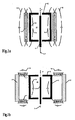
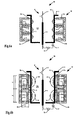
- Variant (A) is the classic variant, with the advantage that such annular magnets 1 with axial magnetization are simple and inexpensive to manufacture. In combination with suitable baffles made of soft magnetic material can thus achieve homogeneous Nutzfeldlinien 14 and this magnetic flux densities in the ionization of the meter.
- the cathode 3 is, as already mentioned, cylindrical and encloses the discharge space or a measuring chamber 20 a. In the axis of the cylindrical cathode 3, the anode 4 is arranged. The whole is enclosed by the annular permanent magnet 1 with axial polarity alignment to the axis 7. In the FIG. 1a the north pole is denoted by N and the south pole by S. The polarities can also be reversed within the arrangement.
- the cylindrical cathode directed towards the axis 7, can have further electrode surfaces which are at the same potential and additionally reflect the electrons back into the discharge space.
- the discharge space has at least one opening which communicates with the outside to be measured with the vacuum space P.
- a measuring cell is formed there as a releasable flange connection.
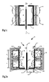
- the variant (B) has two radially magnetized spaced from each other in the axial direction rings, which are connected via an annular yoke 2 made of soft magnetic material for the conclusion of the magnetic circuit.
- variant (B) has smaller stray fields 15 towards the outside, in particular in the radial direction. A portion of the generated magnetic field 15 closes outside the ionization space and forms a stray field 15 and this contributes nothing to the payload field 14 at.
- Such external stray fields 15 are disadvantageous because these devices and processes located there can interfere.
- the variant (B) with the smaller stray field 15 against the outside is consequently more advantageous in this regard. However, this also means that less permanent magnet material has to be used for the same flux densities in the ionization space.
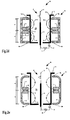
- Variant (C) was from Drubetsky & Taylor, US 5,568,053 , proposed. It results in a field that changes the direction with respect to the cylinder axis at the height between the two magnetic rings. On the cylinder axis, the field is even zero in this area, because the flux densities of the two magnets cancel each other out.
- the advantage of this arrangement is a smaller stray field compared to variant (A) for given flow density requirements in the measuring chamber.
- the stray field is still appreciably present and can interfere, especially if a strong field of use is to be generated in the measuring chamber, then the external stray field becomes correspondingly stronger and continues to enter the outside area.
- variant (A) A disadvantage of variant (A) are the relatively strong flux densities, which extend to outside the ionization chamber and even the entire measuring cell arrangement and occur there as stray fields 15, as shown in FIG. 1 a is shown. This has detrimental effects on nearby devices and on processes that may occur in the nature of typical use in the immediate vicinity of the measuring cell, particularly in processes operated with charge carriers or ionized gas.
- variant (B) reduces such stray fields 15 by forming a magnetic closure outside the ionization chamber, between the two ring magnets 1, by arranging a guide plate 2 or a yoke made of soft magnetic material. However, significantly disturbing external stray fields 15 due to the magnetic shunt between the poles N, S in each of the two ring magnets 1 continue to form, as shown in FIGS FIG. 2b is shown.
- the gas discharge is small due to the small, no longer perpendicular to the electric field axis magnetic flux density in the center at the height between the two magnetic rings and therefore remains a part of the measuring cell volume unused.
- a non-negligible disturbing Stray field 15 as in the Figure 1c is shown and which acts approximately similar to that previously to variant (A), according to the FIG. 1a , has been explained.
- the present invention has the object of providing a magnetic field configuration for a cold cathode ionization vacuum measuring cell which includes a magnetron arrangement and in which disturbing stray magnetic fields outside the measuring cell are substantially reduced, or even substantially avoided altogether.
- the measuring cell should also be able to detect a large pressure range to be measured and work reliably and reproducibly. Furthermore, this should be compact and economical to produce.
- the arrangement with the magnet system forms a magnetron.
- the first, outer electrode can be operated as an anode, wherein the second, inner electrode is operated as a cathode.
- the much preferred arrangement forms an inverted magnetron.
- the outer, first electrode is operated as a cathode and the coaxial inner electrode is operated as an anode.
- the discharge efficiency is much better and more stable.
- the preferably arranged in the center anode is preferably formed rod-shaped.
- the magnet system thus always has soft magnetic material in the outer region.
- the bilateral magnetic closure between the poles passes over the soft magnetic material. This avoids that the magnet system generates a disturbing stray field towards the outside or at least minimizes such a stray field.
- at least two annular, tunnel-like, inwardly directed magnetic field configurations are formed over the surface of the first electrode, each having an axial component.
- the field lines go from the inner pole of the at least one permanent magnet inwards and penetrate the first electrode, which close on both sides of the magnet on the poles of the soft magnetic yoke, in turn, by penetrating the first electrode.
- the field lines at the height of the magnet within the ionization chamber change direction, whereby the two adjacent tunnel-like fields, in their polarity, run in opposite directions. This results in at least two adjacent annular toroidal discharges over the first electrode.
- the electrons rotating therein oscillate laterally along the field lines as viewed in cross-section and rotate in a circle within the rings in the opposite direction and cause a high degree of ionization, which is typical of the magnetron effect in a well-designed magnetron arrangement, due to the extended residence time. of the present kind.
- a first embodiment of an ionization vacuum measuring cell 30 with a magnetron magnetic field arrangement 19 according to the invention is shown for example in US Pat FIG. 2a shown schematically and in cross section.
- a housing 10 has a measuring port 8 and this can be connected to the vacuum to be measured, whereby the housing 10 is evacuated accordingly.
- the connection between this housing 10 and the container with the vacuum to be measured can be done for example via a sealing flange.
- the vacuum measuring cell 30 comprises the housing 10, with two electrodes 3, 4 and a magnet system 19, wherein in the present embodiment, the housing 10 enclose them.
- the magnet system 19 includes a Permanent magnet ring 1 and a yoke 2 made of soft magnetic material.
- the soft magnetic material may include both metallic materials (ferromagnetic), as well as ceramic materials such as ferrites.
- the first and a second electrodes 3, 4 are arranged substantially coaxially and spaced from one another and have a common axis 7.
- the first electrode 3 forms the outer electrode and has a substantially cylindrical surface.
- the second electrode 4 may also be cylindrical, but is advantageously designed rod-shaped and is located advantageously in the center, lying in the axis 7.
- Both electrodes can be powered electrically via vacuum-tight, electrical feedthroughs 12, 12 'on the housing 10.
- a voltage source 16 is connected to the electrodes 2, 3.
- Current measuring means 17 are used to evaluate a discharge current, the discharge, which is formed between the electrodes 3, 4. This discharge current corresponds to a function of the vacuum pressure to be measured and is electronically evaluated and supplied for further use.
- At least one permanent magnet ring 1 encloses the coaxial arrangement of the electrodes 3, 4 with the magnetization direction 13 aligned essentially radially with respect to the axis.
- This permanent magnet ring 1 is further surrounded by a yoke 2, which consists of soft magnetic material for guiding the magnetic field.
- the yoke 2 is guided in the axial direction on both sides of the permanent magnet ring 1 away and guided by a predetermined distance d from the permanent magnet ring 1 on both sides in the radial direction to the axis 7 and the first electrode 3. This creates in cross-section a kind of U-shaped yoke, which forms on both sides and spaced from the permanent magnet ring 1 poles 9a and 9b.
- the first electrode 3 is the outer electrode of the coaxial arrangement of the electrodes 3, 4. At least part of the field lines of the permanent magnet ring 1, the Nutzfeldlinien 14 which are decisive for the discharge, thus close over the pole of the permanent magnet ring 1 and the respective Pol 9a, 9b of the yoke 2 within the Measuring chamber 20, the first electrode 3 penetrating, wherein preferably an annular tunnel-like magnetic field 14 is formed over the first electrode 3 within the measuring chamber 20.
- the arrangement according to the FIG. 1a are each a tunnel-like magnetic field 14 formed on both sides of the permanent magnet ring 1, so two annular or toroidal magnetic fields 14 with opposite polarity of the field line course.
- the outer first electrode 3 is preferably operated as a cathode and the inner second electrode 4 as an anode.
- the permanent magnet ring 1 is magnetized in the radial direction and preferably contains magnetic material of the group of rare earths, such as neodymium, samarium, etc.
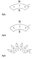
- the magnetization takes place in the indicated arrow direction, in the case of the segment of FIG. 5a in a uniform direction or in the case of the segment of FIG. 5b in the radial direction.
- FIG. 5c be individual, for example, rectangular magnets lined up in a ring.
- the length h is then preferably longer than wide at the individual piece.
- the thickness of the magnetic ring 1 is preferably not greater than the width h.
- the shape of the U-shaped yoke 2 is formed at least partially angled in the sectional plane in which the axis 7, so that in the axial direction at a distance d on both sides of the permanent magnet ring 1, the resulting legs of the yoke 2 in the radial direction to the axis 7 of the measuring cell 30th point and there on both sides each form an annular pole 9a, 9b, which is guided against the first electrode 3 out.
- the bend is formed at right angles, as in the FIGS. 2a to 2d . 3 . 4 and 6 is shown.
- the poles 9a, 9b of the yoke and the inner pole of the permanent magnet ring are preferably equidistant from the axis 7.
- the poles 9a, 9b of the yoke are arranged such that the magnetic field 14 passes through the first electrode 3 there.
- the useful magnetic field 14 thus leads away from the pole of the permanent magnet ring 1 through the first electrode 3 and closes arcuately within the measuring chamber 20 via the two poles 9a, 9b of the yoke 2, where it is again passed through the first electrode 3 therethrough.
- the passage of the magnetic field through the first electrode 3 leads to a high discharge efficiency.
- one or both poles 9a, 9b of the yoke 2 may also be arranged such that the field lines 14 pass only partially or not at all through the first electrode 3, as shown for example in FIG FIG. 2b in the upper area for the one pole 9a is shown.
- the first electrode 3 is shown angled towards the axis, so that also there the field lines 14 again pass through the first electrode 3.
- the first electrode 3 forms a kind of closed cylinder which has only one opening 8 for the supply of the sample gas P and possibly means for supporting the second electrode within this cylinder with an electrical feedthrough for feeding the second electrode.
- FIG. 2a the elements of the measuring cell 30, the magnet system 19 and the two electrodes 3, 4 are enclosed by a vacuum-tight housing 10.
- This housing 10 has an opening 8 and a connection 11, preferably designed as a flange, with which the measuring cell 30 communicating with the vacuum volume to be measured, sealingly connected.
- This connection is advantageously designed as a detachable connection, whereby the measuring cell 30 can be treated as a component easily replaceable.
- FIG. 2b Another possible embodiment of the measuring cell 30 with the housing 10 is in the FIG. 2b shown.
- the yoke 2 of the magnet system is simultaneously formed as a vacuum-tight housing 10 with connection means 11 arranged thereon.
- the yoke 2 may also be part of the housing 10 only.
- the housing 10 may be made partly of soft magnetic or ferromagnetic material and partly of non-magnetic material, such as inox.
- the housing 10 may be disposed between the first electrode 3 and the magnet system 19, such that the magnet system comes to rest outside of the vacuum enclosing housing 10. This has the advantage that the materials of the magnet system 19 can not contaminate or contaminate the space of the measuring chamber 20, as a result of which the measurement result could be unfavorably influenced.
- the first electrode 3 can also be formed as a vacuum-tight housing 10 at the same time. This also enables the magnetic system 19 to be vacuum-separated from the measuring chamber 20 and also a compact, simple design of the measuring cell 30.
- the permanent magnet ring 1 can be arranged asymmetrically within the yoke 2 between its legs with the two poles 9a, 9b in the axial direction or even displaceable, as shown in the FIG. 4 is shown with the arrows 18 indicating the direction of movement.
- the permanent magnet ring 1 is arranged centrally relative to the poles 9 a, 9 b of the yoke 2, so that the poles 9 a, 9 b of the yoke 2 are arranged symmetrically with respect to the permanent magnet ring 1.
- the magnetic field which is directed inwards from the poles, can be influenced by additional conducting means to further optimize the discharge.
- additional conducting means For example, directed in the radial direction towards the axis 7, in the region of the inner pole of the permanent magnet ring (1), ferromagnetic guide means 6 are arranged, as shown in the FIGS. 3 and 4 is shown. Also, for example, directed in the radial direction against the axis 7, in the region of at least one of the inner poles 9a, 9b of the yoke 2, ferromagnetic guide means 5a, 5b are arranged.
- Such guide means can be made as sheet metal parts and / or plates made of soft magnetic or ferromagnetic material, which are for example disc-shaped. As required, openings are provided therein to pass the second electrode 4 and / or to facilitate gas exchange.
- FIG. 6a Another embodiment of the magnet system 19 is shown in FIG. 6a shown, in which two permanent magnet rings 1, axially spaced from each other and opposite to each other, are disposed within the yoke 2.
- This arrangement produces a particularly strong annular magnetron field between the two poles of the permanent magnet rings 1 on the first electrode 3 within the measuring chamber 20.
- On both sides then run ever another annular field, which are completed by the two poles 9a, 9b of the yoke 2 and As a result, stray fields passing outwards are avoided.
- FIG. 6b Another embodiment of the magnet system 19 is in the FIG. 6b shown.
- a further ring magnet 21a, 21b is arranged each which is magnetized in the axial direction and which are arranged in the area against the axis 7 within the magnet system.
- the thickness of the magnetic ring 21 in the radial direction is at most half the width h of the permanent magnet ring 1.
- the measuring cell 30, for example, operated at a voltage of 3.3 kV between the two electrodes 3, 4, ie between the cathode 3 and anode 4.
- the preferred range for the operation of the measuring cell 30 is between 2.0 kV and 4.5 kV.
- the flux density on the cylinder axis, measured within the measuring chamber in the axial direction, is in the range of 10 mT (milli Tesla) to 300 mT, preferably in the range of 60 to 130 mT.
- these lowest achievable limit values are at most about 0.01 mT corresponding to 0.1 Gauss, which is approximately the order of magnitude of the geomagnetic field measured at the earth's surface.
Description
Die Erfindung bezieht sich auf eine lonisations - Vakuummesszelle gemäss dem Oberbegriff des Patentanspruches 1.The invention relates to an ionization vacuum measuring cell according to the preamble of
Es ist bekannt Gasdruckmesszellen für die Vakuummessung einzusetzen, welche auf dem Prinzip einer Gasentladung mit einer kalten Kathode basieren. Derartige Messzellen werden auch als Kaltkathoden - lonisationsvakuummeter oder auch als Penning - Zellen bezeichnet. Bei einer derartigen Messzelle wird zwischen zwei Elektroden (Anode, Kathode) eine hinreichend hohe Gleichspannung angelegt, wodurch eine Gasentladung gezündet und unterhalten werden kann. Der Entladungsstrom ist dann ein Mass für den zu messenden Druck.It is known to use gas pressure measuring cells for the vacuum measurement, which are based on the principle of a gas discharge with a cold cathode. Such measuring cells are also referred to as cold cathode ionization gauge or Penning cells. In such a measuring cell, a sufficiently high DC voltage is applied between two electrodes (anode, cathode), whereby a gas discharge can be ignited and maintained. The discharge current is then a measure of the pressure to be measured.
Ein Magnetfeld, ausgebildet im Bereich der Entladungsstrecke, führt die Elektronen auf ihrem Weg von der negativen Elektrode (Kathode) zur positiven Elektrode (Anode) auf spiralartigen Bahnen wodurch die Bahn der Elektronen verlängert wird. Hierdurch wird die Trefferwahrscheinlichkeit mit den Gasteilchen erhöht und der Ionisierungsgrad verbessert. Dadurch wird erreicht, dass die Entladung über weite Druckbereiche brennen kann und sich stabil und reproduzierbar verhält.A magnetic field formed in the region of the discharge gap carries the electrons on their way from the negative electrode (cathode) to the positive electrode (anode) in spiral-like paths, thereby extending the trajectory of the electrons. This increases the probability of hit with the gas particles and improves the degree of ionization. This ensures that the discharge can burn over wide pressure ranges and behaves stable and reproducible.
Vakuummessgeräte, welche auf dem Prinzip der Gasentladung mit Kaltkathoden funktionieren, können grob in drei Klassen unterteilt werden, welche sich vor allem in der Konfiguration der Elektroden unterscheiden:
- 1. Penning - Zelle:
Die Anode ist als ringförmiger Zylinder ausgebildet, welche den Entladungsraum umschliesst, wobei Kathodenbleche an beiden Stirnseiten des Anodenringes angeordnet sind. Die Magnetfeldlinien verlaufen parallel zur Achse des Anodenringes. - 2. Magnetron - Zelle:
Die Anode ist als Hohlzylinder ausgebildet mit einer zentralen Achse und mit der Kathode als Stab im Zentrum bzw. in der Achse angeordnet. Die Feldlinien des elektrischen Feldes verlaufen demnach radial. Die Magnetfeldlinien verlaufen parallel zur Zylinderachse. - 3. Zelle mit invertierter Magnetronanordnung :
Zylindergeometrie wie bei der Magnetron - Zelle, aber mit der Anode als stabförmige Anordnung im Zentrum und der Kathode als Hohlzylinder. Die Stirnseiten des Zylinders sind typischerweise auch auf Kathodenpotential. Wie beim Magnetron verlaufen die Magnetfeldlinien parallel zur Zylinderachse, die Feldlinien des elektrischen Feldes radial.
- 1. Penning - Cell:
The anode is designed as an annular cylinder, which encloses the discharge space, wherein cathode plates are arranged on both end sides of the anode ring. The magnetic field lines are parallel to the axis of the anode ring. - 2. Magnetron - Cell:
The anode is designed as a hollow cylinder with a central axis and arranged with the cathode as a rod in the center or in the axis. The field lines of the electric field are therefore radial. The magnetic field lines are parallel to the cylinder axis. - 3. Cell with inverted magnetron arrangement:
Cylinder geometry as in the magnetron cell, but with the anode as a rod-shaped arrangement in the center and the cathode as a hollow cylinder. The faces of the cylinder are typically also at cathode potential. As with the magnetron, the magnetic field lines are parallel to the cylinder axis, the field lines of the electric field are radial.
Der dem zu messenden Gas zugängliche Raum, der beim Invertierten Magnetron von der Kathode, beim Magnetron von der Anode umschlossen wird, wird auch als Ionisationsraum bezeichnet.The space accessible to the gas to be measured, which is enclosed by the cathode in the case of the inverse magnetron, and by the anode in the case of the magnetron, is also referred to as the ionization space.
Das am meisten verwendete Design ist dasjenige des invertierten Magnetrons, da es im Allgemeinen ein stabileres Messsignal als die Penning - Zelle im Hochvakuum ergibt, die Entladung bei tiefen Drücken leichter zündet und der untere Messbereich für tiefere Drücke bis hin in den Bereich 10-11 mbar gebracht werden kann.The most widely used design is that of the inverted magnetron, since it generally gives a more stable measurement signal than the Penning cell in high vacuum, firing discharge more easily at low pressures, and the lower measurement range for lower pressures up to 10 -11 mbar can be brought.
Das für die Aufrechterhaltung der Gasentladung benötigte Magnetfeld in Richtung der Zylinderachse wird in Messgeräten wegen den erforderlichen Feldstärken in der Grössenordnung von bis zu 10-1 T (=1000 Gs) durch Permanentmagnete erzeugt, weil die Leistungsaufnahme von Elektromagneten zu hoch sind und diese eine grosse Bauweise bedingen würden. Folgende Magnetkonfigurationen für invertierte Magnetron - Zellen werden dabei nach dem Stand der Technik angewandt:
- A) Ringmagnet mit axialer Magnetisierung, schematisch und beispielsweise dargestellt in der
Figur 1a - B) Zwei Ringmagnete mit radialer Magnetisierung, schematisch und beispielsweise dargestellt in der
Figur 1 - C) Zwei Ringmagnete mit axialer Magnetisierung, welche mit umgekehrter Polarität zueinander stehen, schematisch und beispielsweise dargestellt in der Figur 1c.
- A) Ring magnet with axial magnetization, schematically and for example shown in the
FIG. 1a , - B) Two ring magnets with radial magnetization, schematically and shown for example in the
FIG. 1 b. - C) Two ring magnets with axial magnetization, which are in opposite polarity to each other, schematically and for example shown in Figure 1c.
Variante (A) ist die klassische Variante, mit dem Vorteil, dass derartige ringförmige Magnete 1 mit axialer Magnetisierung einfach und günstig in der Herstellung sind. In Kombination mit geeigneten Leitblechen aus weichmagnetischem Material lassen sich damit homogene Nutzfeldlinien 14 und hierbei magnetische Flussdichten im Ionisationsraum des Messgerätes erzielen. Die Kathode 3 ist, wie bereits erwähnt, zylinderförmig ausgebildet und schliesst den Entladungsraum bzw. eine Messkammer 20 ein. In der Achse der zylinderförmigen Kathode 3 ist die Anode 4 angeordnet. Das Ganze wird vom ringförmigen Permanentmagneten 1 mit axialer Polaritätsausrichtung zur Achse 7 umschlossen. In der
Die Variante (B) weist zwei radial magnetisierte voneinander in axialer Richtung beabstandeten Ringe auf, die über ein ringförmiges Joch 2 aus weichmagnetischem Material verbunden sind für den Rückschluss des magnetischen Kreises. Im Vergleich zu Variante (A) weist die Variante (B) kleinere Streufelder 15 nach aussen hin, insbesondere in radialer Richtung, auf. Ein Teil des erzeugten Magnetfeldes 15 schliesst sich ausserhalb des Ionisationsraumes und bildet ein Streufeld 15 und dieses trägt nichts zum Nutzfeld 14 bei. Derartige äussere Streufelder 15 sind nachteilig, da diese dort befindliche Geräte und Prozesse stören können. Die Variante (B) mit dem geringeren Streufeld 15 gegen Aussen ist folglich diesbezüglich vorteilhafter. Dies bedeutet aber auch, dass für die gleichen Flussdichten im Ionisationsraum weniger Permanentmagnetmaterial verwendet werden muss.The variant (B) has two radially magnetized spaced from each other in the axial direction rings, which are connected via an
Gemäss dem Vorschlag von
Variante (C) wurde von
Ein Nachteil von Variante (A) sind die relativ starken Flussdichten, die bis ausserhalb der Ionisationskammer und sogar der gesamten Messzellenanordnung reichen und dort als Streufelder 15 auftreten, wie dies in der
Bei Variante (C) ist die Gasentladung durch die kleine, nicht mehr senkrecht zur elektrischen Feldachse stehende, magnetische Flussdichte im Zentrum auf der Höhe zwischen den beiden Magnetringen gering und demnach bleibt ein Teil des Messzellenvolumens ungenutzt. Zudem ergibt sich aus dem magnetischen Nebenschluss auf der Aussenseite der Magnete ein nicht vernachlässigbares störendes Streufeld 15, wie dies in der
Es ist Aufgabe der vorliegenden Erfindung, die Nachteile des Standes der Technik zu beseitigen. Insbesondere stellt sich die vorliegende Erfindung die Aufgabe, eine Magnetfeldkonfiguration für eine Kaltkathode - Ionisations - Vakuummesszelle zur Verfügung zu stellen, die eine Magnetronanordnung beinhaltet und bei welcher störende magnetische Streufelder ausserhalb der Messzelle wesentlich vermindert, oder gar im Wesentlichen ganz vermieden werden. Die Messzelle soll ausserdem einen grossen zu messenden Druckbereich erfassen können und zuverlässig und reproduzierbar arbeiten. Weiterhin soll diese kompakt und wirtschaftlich herstellbar sein.It is an object of the present invention to eliminate the disadvantages of the prior art. In particular, the present invention has the object of providing a magnetic field configuration for a cold cathode ionization vacuum measuring cell which includes a magnetron arrangement and in which disturbing stray magnetic fields outside the measuring cell are substantially reduced, or even substantially avoided altogether. The measuring cell should also be able to detect a large pressure range to be measured and work reliably and reproducibly. Furthermore, this should be compact and economical to produce.
Die Aufgabe wird bei der gattungsgemässen lonisations - Vakuummesszelle gemäss den kennzeichnenden Merkmalen des Patentanspruches 1 gelöst. Die abhängigen Patentansprüche beziehen sich auf vorteilhafte weitere Ausgestaltungen der Erfindung.The object is achieved in the generic ionization - vacuum measuring cell according to the characterizing features of
Die erfindungsgemässe Ionisations - Vakuummesszelle umfasst:
- a) ein evakuierbares Gehäuse mit einem Messanschluss für das zu messende Vakuum,
- b) eine erste und eine zweite Elektrode, die im wesentlichen koaxial und beabstandet zueinander angeordnet sind und mit einer gemeinsamen Achse, wodurch zwischen diesen beiden Elektroden eine Messkammer ausgebildet ist, die mit dem Messanschluss kommunizierend angeordnet ist, wobei die erste Elektrode die äussere Elektrode bildet und diese im wesentlichen eine zylindrische Fläche aufweist,
- c) einer Spannungsquelle, die mit den Elektroden verbunden ist,
- d) ein Strommessmittel zur Auswertung eines Entladungsstromes ausgebildet zwischen den Elektroden, wobei dieser eine Funktion des zu messenden Vakuumdruckes bildet,
- e) mindestens einen Permanentmagnetring, der die koaxiale Anordnung der Elektroden umschliesst, mit im Wesentlichen radial zur Achse ausgerichteter Magnetisierungsrichtung und mit einem diesen Permanentmagnetring umschliessenden weichmagnetischen Joch,
- a) an evacuable housing with a measuring connection for the vacuum to be measured,
- b) a first and a second electrode, which are arranged substantially coaxially and spaced from each other and with a common axis, whereby between these two electrodes a measuring chamber is formed, which is arranged communicating with the measuring terminal, wherein the first electrode forms the outer electrode and this has a substantially cylindrical surface,
- c) a voltage source connected to the electrodes,
- d) a current measuring means for evaluating a discharge current formed between the electrodes, wherein this forms a function of the vacuum pressure to be measured,
- e) at least one permanent magnet ring, which encloses the coaxial arrangement of the electrodes, with a magnetization direction oriented substantially radially to the axis and with a soft-magnetic yoke surrounding this permanent magnet ring,
Die Anordnung mit dem Magnetsystem bildet ein Magnetron. In gewissen Fällen kann die erste, äussere Elektrode als Anode betrieben werden, wobei die zweite, innen liegende Elektrode als Kathode betrieben wird. Die weitaus bevorzugte Anordnung bildet aber ein invertiertes Magnetron. Hierbei wird die aussenliegende, erste Elektrode als Kathode betrieben und die dazu koaxial innen liegende Elektrode wird als Anode betrieben. Bei dieser Anordnung, bezeichnet als invertiertes Magnetron, ist der Entladungswirkungsgrad wesentlich besser und stabiler. Die vorzugsweise im Zentrum angeordnete Anode ist vorzugsweise stabförmig ausgebildet.The arrangement with the magnet system forms a magnetron. In certain cases, the first, outer electrode can be operated as an anode, wherein the second, inner electrode is operated as a cathode. However, the much preferred arrangement forms an inverted magnetron. In this case, the outer, first electrode is operated as a cathode and the coaxial inner electrode is operated as an anode. In this arrangement, referred to as inverted magnetron, the discharge efficiency is much better and more stable. The preferably arranged in the center anode is preferably formed rod-shaped.
Das Magnetsystem weist im aussenliegenden Bereich somit immer weichmagnetisches Material auf. Der beidseitige magnetische Schluss zwischen den Polen verläuft über das weichmagnetische Material. Damit wird vermieden, dass das Magnetsystem nach Aussen hin ein störendes Streufeld generiert oder ein solches zumindest minimiert wird. Innerhalb der Ionisationskammer hingegen bilden sich mindestens zwei ringförmige, tunnelartige, nach innen gerichtete Magnetfeldkonfigurationen über der Fläche der ersten Elektrode mit jeweils einer axialen Komponente. Die Feldlinien gehen vom inneren Pol des mindestens einen Permanentmagneten aus nach innen und durchdringen die erste Elektrode, wobei sich diese beidseitig des Magneten über die Pole des weichmagnetischen Joches schliessen, indem sie wiederum die erste Elektrode durchdringen. Hierbei ändern die Feldlinien auf der Höhe des Magneten innerhalb der Ionisationskammer die Richtung, wodurch die beiden benachbarten tunnelartigen Felder, in ihrer Polarität, entgegengesetzt verlaufen. Dadurch entstehen mindestens zwei nebeneinander liegende ringförmige, torusartige Entladungen über der ersten Elektrode. Die darin rotierenden Elektronen pendeln, im Querschnitt betrachtet, entlang der Feldlinien seitlich hin und her und rotieren kreisförmig innerhalb der Ringe in entgegen gesetzter Richtung und bewirken durch die dadurch verlängerte Verweilzeit einen hohen Ionisierungsgrad, der typisch ist für den Magnetroneffekt bei einer gut ausgelegten Magnetronanordnung, der vorliegenden Art.The magnet system thus always has soft magnetic material in the outer region. The bilateral magnetic closure between the poles passes over the soft magnetic material. This avoids that the magnet system generates a disturbing stray field towards the outside or at least minimizes such a stray field. Within the ionization chamber, however, at least two annular, tunnel-like, inwardly directed magnetic field configurations are formed over the surface of the first electrode, each having an axial component. The field lines go from the inner pole of the at least one permanent magnet inwards and penetrate the first electrode, which close on both sides of the magnet on the poles of the soft magnetic yoke, in turn, by penetrating the first electrode. Here, the field lines at the height of the magnet within the ionization chamber change direction, whereby the two adjacent tunnel-like fields, in their polarity, run in opposite directions. This results in at least two adjacent annular toroidal discharges over the first electrode. The electrons rotating therein oscillate laterally along the field lines as viewed in cross-section and rotate in a circle within the rings in the opposite direction and cause a high degree of ionization, which is typical of the magnetron effect in a well-designed magnetron arrangement, due to the extended residence time. of the present kind.
Die Erfindung wird nun anhand von Figuren schematisch und beispielsweise beschrieben.The invention will now be described schematically and by way of example with reference to FIGS.
Es zeigen:
- Fig. 1a
- im Querschnitt, eine Magnetron - Ionisations - Vakuummesszelle mit einem Ringmagnet mit axialer Magnetisierung, gemäss Stand der Technik,
- Fig. 1b
- im Querschnitt, eine Magnetron - Ionisations - Vakuummesszelle mit zwei in axialer Richtung voneinander beabstandeten Ringmagneten mit radialer Magnetisierung, welche ein aussen umgebendes weichmagnetisches Joch umgibt, gemäss Stand der Technik,
- Fig. 1c
- im Querschnitt, eine Magnetron - Ionisations - Vakuummesszelle mit zwei Ringmagneten mit axialer Magnetisierung, die gegenpolig zueinander und aneinander anstossend positioniert sind, gemäss Stand der Technik,
- Fig. 2a
- im Querschnitt eine Magnetron - Ionisations - Vakuummesszelle mit einem Ringmagnet mit radialer Magnetisierung und aussen angeordnetem umschliessenden weichmagnetischen Joch, welches beidseitig des Ringmagneten und von diesem beabstandet schenkelartige Bereiche aufweisen, die jeweils einen ringförmigen Pol bilden, die gegen eine erste Elektrode hin gerichtet sind, wobei ein Vakuumgehäuse die ganze Anordnung der Messzelle umschliesst und aufnimmt, entsprechend der vorliegenden Erfindung,
- Fig. 2b
- eine weitere Ausbildung einer Vakuummesszelle, wobei das Vakuumgehäuse durch das Joch selber ausgebildet ist,
- Fig. 2c
- eine weitere Ausbildung einer Vakuummesszelle, wobei das Vakuumgehäuse zwischen der ersten Elektrode und der Anordnung des Magnetsystems angeordnet ist, derart dass das Magnetsystem aus Permanentmagnet und Joch ausserhalb der Vakuumkammer liegt im Bereich von Atmosphäre,
- Fig. 2d
- eine weitere Ausbildung einer Vakuummesszelle, wobei das Vakuumgehäuse gleichzeitig als erste Elektrode ausgebildet ist, derart dass das Magnetsystem aus Permanentmagnet und Joch ausserhalb der Vakuumkammer liegt im Bereich von Atmosphäre,
- Fig. 2e
- eine weitere Ausbildung einer Vakuummesszelle, wobei die schenkelartigen Bereiche mit den Polen gebogen gegen die erste Elektrode hin geführt werden,
- Fig. 3
- im Querschnitt eine weitere Ausbildung einer Vakuummesszelle, wobei im zentralen Bereich der Messzelle über den Polen des Joches und / oder dem Pol des Ringmagneten weichmagnetische Leitmittel angeordnet sind,
- Fig. 4
- im Querschnitt eine weitere Ausbildung einer Vakuummesszelle, wobei der Ringmagnet und / oder die dem Pol zugehörigen weichmagnetischen Leitmittel innerhalb der Anordnung des Joches in axialer Richtung asymmetrisch und / oder verschiebbar angeordnet ist,
- Fig. 5a
- in der Aufsicht eine Darstellung eines Segmentes als Teil eines zusammengesetzten Ringmagneten bei welchem die Magnetisierungsrichtung senkrecht zur Sehne des Segmentes ausgerichtet ist,
- Fig. 5b
- in der Aufsicht eine Darstellung eines Segmentes als Teil eines zusammengesetzten Ringmagneten mit radial gerichteter Magnetisierungsrichtung,
- Fig. 5c
- in der Aufsicht eine Teildarstellung eines aus einzelnen Stabmagneten zusammengesetzten Ringmagneten, wobei die einzelnen Stabmagnete in gleicher Richtung magnetisiert sind,
- Fig. 6a
- im Querschnitt eine weitere Ausbildung einer Vakuummesszelle, wobei zwei voneinander axial beabstandete Ringmagnete innerhalb der Anordnung des Joches dargestellt sind,
- Fig. 6b
- im Querschnitt eine weitere Ausbildung einer Vakuummesszelle, wobei je ein weiterer Ringmagnet mit axialer Polarisierung beidseitig des Poles des radial magnetisierten Ringmagneten und zueinander gegenpolig und gegen die Achse hin gerichtet innerhalb der Anordnung des Joches angeordnet sind.
- Fig. 1a
- in cross section, a magnetron ionization vacuum measuring cell with a ring magnet with axial magnetization, according to the prior art,
- Fig. 1b
- in cross-section, a magnetron ionization vacuum measuring cell with two ring magnets with radial magnetization spaced apart in the axial direction, which surrounds a soft magnetic yoke surrounding the outside, according to the prior art,
- Fig. 1c
- in cross-section, a magnetron ionization vacuum measuring cell with two ring magnets with axial magnetization, which are positioned opposite to each other and abutting one another, according to the prior art,
- Fig. 2a
- in cross section a magnetron ionization vacuum measuring cell with a ring magnet with radial magnetization and arranged outside enclosing soft magnetic yoke having on both sides of the ring magnet and spaced therefrom leg-like regions, each forming an annular pole, which are directed against a first electrode, a vacuum housing enclosing and receiving the entire array of the measuring cell, according to the present invention,
- Fig. 2b
- a further embodiment of a vacuum measuring cell, wherein the vacuum housing is formed by the yoke itself,
- Fig. 2c
- a further embodiment of a vacuum measuring cell, wherein the vacuum housing is arranged between the first electrode and the arrangement of the magnet system, such that the magnet system of permanent magnet and yoke outside the vacuum chamber is in the range of atmosphere,
- Fig. 2d
- a further embodiment of a vacuum measuring cell, wherein the vacuum housing is simultaneously formed as a first electrode, such that the magnetic system of permanent magnet and yoke outside the vacuum chamber is in the range of atmosphere,
- Fig. 2e
- a further embodiment of a vacuum measuring cell, wherein the thigh-like regions are guided with the poles bent towards the first electrode,
- Fig. 3
- in cross-section, a further embodiment of a vacuum measuring cell, wherein in the central region of the measuring cell over the poles of the yoke and / or the pole of the ring magnet soft magnetic conducting means are arranged,
- Fig. 4
- a further embodiment of a vacuum measuring cell in cross-section, wherein the ring magnet and / or the soft-magnetic conducting means associated with the pole is arranged asymmetrically and / or displaceably in the axial direction within the arrangement of the yoke,
- Fig. 5a
- in the plan view of a segment as part of a composite ring magnet in which the magnetization direction is aligned perpendicular to the chord of the segment,
- Fig. 5b
- in the plan view of a segment as part of a composite ring magnet with radially directed magnetization direction,
- Fig. 5c
- in the plan view a partial representation of a composite of individual bar magnet ring magnet, wherein the individual bar magnets are magnetized in the same direction,
- Fig. 6a
- in cross-section, another embodiment of a vacuum measuring cell, wherein two axially spaced apart ring magnets are shown within the arrangement of the yoke,
- Fig. 6b
- in cross-section, a further embodiment of a vacuum measuring cell, wherein each a further ring magnet with axial polarization on both sides of the pole of the radially magnetized ring magnet and mutually opposite poles and directed against the axis are arranged within the arrangement of the yoke.
Eine erste Ausführungsform einer Ionisations - Vakuummesszelle 30 mit einer Magnetron - Magnetfeldanordnung 19, gemäss der Erfindung, ist beispielsweise in der
Ein Gehäuse 10 weist einen Messanschluss 8 auf und dieser kann mit dem zu messende Vakuum verbunden werden, wodurch das Gehäuse 10 entsprechend evakuiert wird. Die Verbindung zwischen diesem Gehäuse 10 und dem Behälter mit dem zu messenden Vakuum kann beispielsweise über einen dichtenden Flansch erfolgen. Die Vakuummesszelle 30 umfasst das Gehäuse 10, mit zwei Elektroden 3, 4 und einem Magnetsystem 19, wobei in der vorliegenden Ausführung das Gehäuse 10 diese umschliessen. Das Magnetsystem 19 beinhaltet einen Permanentmagnetring 1 und ein Joch 2 aus weichmagnetischem Material. Das weichmagnetische Material kann sowohl metallische Werkstoffe (ferromagnetische), wie auch keramische Werkstoffe, wie beispielsweise Ferrite, umfassen. Die erste und eine zweite Elektrode 3, 4 sind im wesentlichen koaxial und beabstandet zueinander angeordnet und weisen eine gemeinsame Achse 7 auf. Hierdurch wird zwischen diesen beiden Elektroden eine Messkammer 20 ausgebildet. Diese wiederum ist mit dem Messanschluss 8 kommunizierend angeordnet. Die erste Elektrode 3 bildet die äussere Elektrode und weist im wesentlichen eine zylindrische Fläche auf. Die zweite Elektrode 4 kann ebenfalls zylindrisch ausgebildet sein, ist aber mit Vorteil stabförmig ausgebildet und ist mit Vorteil im Zentrum, in der Achse 7 liegend, angeordnet.A
Beide Elektroden können über vakuumdichte, elektrische Durchführungen 12, 12' am Gehäuse 10 elektrisch gespiesen werden. Hierzu wird eine Spannungsquelle 16 mit den Elektroden 2, 3 verbunden. Strommessmittel 17 dienen der Auswertung eines Entladungsstromes, der Entladung, die ausgebildet wird zwischen den Elektroden 3, 4. Dieser Entladungsstrom entspricht einer Funktion des zu messenden Vakuumdruckes und wird elektronisch ausgewertet und der weiteren Verwendung zugeführt.Both electrodes can be powered electrically via vacuum-tight,
Mindestens ein Permanentmagnetring 1, umschliesst die koaxiale Anordnung der Elektroden 3, 4 mit im Wesentlichen radial zur Achse ausgerichteter Magnetisierungsrichtung 13. Dieser Permanentmagnetring 1 wird weiter von einem Joch 2 umschlossen, welches aus weichmagnetischem Material besteht zur Führung des magnetischen Feldes. Das Joch 2 ist in axialer Richtung beidseitig vom Permanentmagnetring 1 weg geführt und nach einem vorgegebenen Abstand d vom Permanentmagnetring 1 auf beiden Seiten in radialer Richtung hin zur Achse 7 und der ersten Elektrode 3 geführt. Dadurch entsteht im Querschnitt eine Art U-förmiges Joch, welches beidseitig und beabstandet vom Permanentmagnetring 1 Pole 9a und 9b ausbildet. Hierbei ist die erste Elektrode 3 die aussen liegende Elektrode der koaxialen Anordnung der Elektroden 3, 4. Mindestens ein Teil der Feldlinien des Permanentmagnetringes 1, die Nutzfeldlinien 14 welche für die Entladung bestimmend sind, schliessen sich somit über dem Pol des Permanentmagnetringes 1 und dem jeweiligen Pol 9a, 9b des Joches 2 innerhalb der Messkammer 20, die erste Elektrode 3 durchdringend, wobei vorzugsweise ein ringförmiges tunnelartiges Magnetfeld 14 über der ersten Elektrode 3 innerhalb der Messkammer 20 ausgebildet wird. Bei der Anordnung gemäss der
Die aussen liegende erste Elektrode 3 wird vorzugsweise als Kathode betrieben und die innen liegende zweite Elektrode 4 als Anode.The outer
Der Permanentmagnetring 1 ist in radialer Richtung magnetisiert und enthält vorzugsweise Magnetmaterial der Gruppe seltener Erden, wie Neodym, Samarium etc. Um die Herstellung zu vereinfachen kann der Ring auch aus einzelnen Teilen zusammengesetzt werden, wie aus Segmenten und / oder einzelnen rechteckförmigen Magneten, die dann ringförmig aneinander gereiht werden, wie dies in den
Die Form des U - förmigen Joches 2 ist in Schnittebene in der die Achse 7 liegt mindestens teilweise abgewinkelt ausgebildet, derart dass in axialer Richtung im Abstand d beidseitig zum Permanentmagnetring 1 die dadurch entstehenden Schenkel des Joches 2 in radialer Richtung zur Achse 7 der Messzelle 30 hin weisen und dort beidseitig je einen ringförmigen Pol 9a, 9b ausbilden, der gegen die erste Elektrode 3 hin geführt ist. Vorzugsweise ist die Abwinkelung rechtwinklig ausgebildet, wie dies in den
Neben der abgewinkelten Ausbildung der Schenkel des Joches 2 können mindestens Teile davon auch mindestens teilweise bogenförmig in radialer Richtung zur ersten Achse 7 oder zur Elektrode 3 hin geführt sein, wie dies in der
Im gezeigten Beispiel der
Diese Verbindung ist mit Vorteil als lösbare Verbindung ausgebildet, wodurch die Messzelle 30 als Komponente einfach austauschbar behandelt werden kann.This connection is advantageously designed as a detachable connection, whereby the measuring
Eine weitere mögliche Ausbildung der Messzelle 30 mit dem Gehäuse 10 ist in der
In einer weiteren Variante, gemäss der
In der Variante nach der
Der Permanentmagnetring 1 kann innerhalb des Joches 2 zwischen dessen Schenkeln mit den beiden Polen 9a, 9b in axialer Richtung asymmetrisch angeordnet werden oder gar verschiebbar, wie dies in der
Das Magnetfeld, welches von den Polen ausgehend nach innen gerichtet ist kann mit zusätzlichen Leitmitteln beeinflusst werden, um die Entladung weiter zu optimieren. Beispielsweise können in radialer Richtung gegen die Achse 7 hin gerichtet, im Bereich des innen liegenden Poles des Permanentmagnetringes (1), ferromagnetische Leitmittel 6 angeordnet werden, wie dies in den
Eine weitere Ausführungsform des Magnetsystems 19 ist in der
Eine weitere Ausführung des Magnetsystems 19 ist in der
Die Messzelle 30, gemäss der zuvor beschriebenen Erfindung, wird beispielsweise mit einer Spannung von 3.3 kV betrieben zwischen den beiden Elektroden 3, 4, also zwischen Kathode 3 und Anode 4. Der Bevorzugte Bereich für den Betrieb der Messzelle 30 liegt zwischen 2.0 kV und 4.5 kV.The measuring
Nachfolgend werden Dimensionen angegeben für die wichtigen Teile.Below dimensions are given for the important parts.
Die zweite Elektrode 4 (Anode):
- Länge der Anode: beispielsweise 20 mm, mit dem
bevorzugten Bereich von 10bis 30 mm. - Durchmesser der Anode: beispielsweise 1.0 bis 1.5 mm, mit dem bevorzugten Bereich von 1.0 bis 5.0 mm.
- Material: nicht magnetisch (auch para- oder diamagnetisch).
- Length of the anode: for example, 20 mm, with the preferred range of 10 to 30 mm.
- Diameter of the anode: for example, 1.0 to 1.5 mm, with the preferred range of 1.0 to 5.0 mm.
- Material: non-magnetic (also para- or diamagnetic).
Die erste Elektrode 3 (Kathode):
- Länge der Kathode: beispielsweise 20 mm, mit dem
bevorzugten Bereich von 10bis 30 mm. - Durchmesser der Kathode: beispielsweise 20 bis 25 mm, mit dem
bevorzugten Bereich von 15 bis 35 mm. - Material: nicht magnetisch (auch para- oder diamagnetisch).
- Length of the cathode: for example 20 mm, with the preferred range of 10 to 30 mm.
- Diameter of the cathode: for example 20 to 25 mm, with the preferred range of 15 to 35 mm.
- Material: non-magnetic (also para- or diamagnetic).
Der Permanentmagnetring 1:
- Höhe in axialer Richtung: beispielsweise 5.0 mm, mit dem bevorzugten Bereich von 3.0
bis 10 mm. - Breite h in radialer Richtung: beispielsweise 5.0 mm, mit dem bevorzugten Bereich von 3.0
bis 10 mm.
- Height in the axial direction: for example, 5.0 mm, with the preferred range of 3.0 to 10 mm.
- Width h in the radial direction: for example, 5.0 mm, with the preferred range of 3.0 to 10 mm.
Die Flussdichte auf der Zylinderachse, gemessen innerhalb der Messkammer in axialer Richtung, liegt im Bereich von 10 mT (milli Tesla) bis 300 mT, vorzugsweise im Bereich von 60 bis 130 mT.The flux density on the cylinder axis, measured within the measuring chamber in the axial direction, is in the range of 10 mT (milli Tesla) to 300 mT, preferably in the range of 60 to 130 mT.
-
Kleiner 2.0 mT im Abstand von 30 mm in radialer Richtung von der Aussenkante der Messzelle 30, vorzugsweise kleiner 0.5 mT.Smaller 2.0 mT at a distance of 30 mm in the radial direction from the outer edge of the measuring
cell 30, preferably less than 0.5 mT. -
Kleiner 2.0 mT im Abstand von 30 mm von der Vorder- oder Rückseitenkante in axialer Richtung der Messzelle 30, vorzugsweise kleiner 0.5 mT.Smaller 2.0 mT at a distance of 30 mm from the front or rear edge in the axial direction of the measuring
cell 30, preferably less than 0.5 mT.
Das Streufeld kann in beiden Fällen als tiefste Werte nicht null Werte erreichen. Diese tiefsten erreichbaren Grenzwerte liegen im günstigsten Fall höchstens bei etwa 0.01 mT entsprechend 0.1 Gauss, was etwa in der Grössenordnung des Erdmagnetfeldes liegt gemessen an der Erdoberfläche.In both cases, the stray field can not reach zero values as the lowest values. In the best case, these lowest achievable limit values are at most about 0.01 mT corresponding to 0.1 Gauss, which is approximately the order of magnitude of the geomagnetic field measured at the earth's surface.
Claims (17)
- An ionization vacuum measurement cell comprising:a) an evacuatable housing (10) with a measurement connection (8) for the vacuum to be measured,b) a first and second electrode (3, 4) having a common axis (7) and arranged substantially coaxially and spaced apart to each other, whereby a measurement chamber (20) is formed between these two electrodes, which is arranged in communication with the measurement connection (8), wherein the first electrode (3) forms the outer electrode comprising a substantially cylindrical surface,c) wherein the electrodes (3, 4) are connectable to a voltage source (16), andd) a current measurement means (17) is connectable between the electrodes (3, 4) for evaluating a discharge current, the discharge current being a function of the vacuum pressure to be measured,e) at least one permanent magnet ring (1) surrounding the coaxial arrangement of the electrodes (3, 4), having a magnetisation direction (13) which is substantially radial to the axis, and with a soft-magnetic yoke (2) surrounding the permanent magnet ring (1),characterised in that said yoke (2) extends axially away from the permanent magnet ring (1) on both sides, and extends in a radial direction to the axis (7) and the first electrode (3) on both sides at a predetermined distance (d) from the permanent magnet ring (1), wherein said first electrode (3) forms the outer electrode of the coaxial arrangement of the electrodes (3, 4), such that the yoke (2) forms two annular poles (9a, b) on both sides of the permanent magnet ring (1) and spaced apart therefrom, through which at least a part of the field lines of the permanent magnet ring (1) form a closed loop within the measurement chamber (20), penetrating the first electrode (3), wherein preferably an annular tunnel-like magnetic field (14) is generated above the first electrode (3) inside the measurement chamber (20).
- The measurement cell according to claim 1, characterised in that the outer electrode (3) is a cathode and the inner electrode (4) is an anode.
- The measurement cell according to one of the preceding claims, characterised in that the yoke (2) is at least partially arcuately directed towards the first electrode (3) in a radial direction in a sectional plane in which the axis (7) lies.
- The measurement cell according to one of the preceding claims, characterised in that the yoke (2) is at least partially angled, preferably orthogonally, directed towards the first electrode (3) in a radial direction in a sectional plane in which the axis (7) lies.
- The measurement cell according to one of the preceding claims, characterised in that at least two permanent magnet rings (1) having opposite directions of magnetisation (13) are arranged inside the yoke (2) with both poles (9a, b) spaced apart from each other in axial direction, wherein each permanent magnet ring pair forms a further annular and tunnel-like magnetic field (14) above the first electrode (3) .
- The measurement cell according to claim 5, characterised in that two permanent magnet rings (1) having opposite directions of magnetisation (13) are arranged inside the yoke (2) with both poles (9a, b) spaced apart from each other in axial direction.
- The measurement cell according to one of the preceding claims, characterised in that the housing (10) encloses the permanent magnet ring (1) comprising the yoke (2) as well as both electrodes (3, 4).
- The measurement cell according to claim 7, characterised in that the yoke (2) forms part of the housing (10).
- The measurement cell according to one of claims 1 to 6, characterised in that the housing (10) is arranged between the first electrode (3) and the permanent magnet ring (1) with the yoke (2) such that the permanent magnet ring (1) and the yoke (2) are arranged separated from the vacuum.
- The measurement cell according to one of claims 1 to 6, characterised in that the first electrode (3) is formed as the housing (10).
- The measurement cell according to one of the preceding claims, characterised in that the at least one permanent magnet ring (1) is arranged in axial direction inside the yoke (2) spaced apart unequally in relation to the poles (9a, b).
- The measurement cell according to one of the preceding claims, characterised in that the at least one permanent magnet ring (1) is arranged in axial direction inside the yoke (2) displaceably in relation to the poles (9a, b).
- The measurement cell according to one of the preceding claims, characterised in that soft-magnetic conductive means (6) are arranged in the area of the inner pole of the permanent magnet ring (1) directed in radial direction towards the axis (7).
- The measurement cell according to one of the preceding claims, characterised in that ferromagnetic conductive means (5a, 5b) are arranged in the area of at least one of the inner poles (9a, b) of the yoke (2) directed in radial direction towards the axis (7).
- The measurement cell according to claim 13 or 14, characterised in that the soft-magnetic conductive means (6, 5a, 5b) are formed disk-like.
- The measurement cell according to one of the claims 13 to 15, characterised in that the ferromagnetic conductive means (6, 5a, 5b) feature openings for feeding-through the second electrode (4) and/or to allow passage of measurement gas.
- The measurement cell according to one of the preceding claims, characterised in that the second electrode (4) is formed rod-like.
Applications Claiming Priority (2)
| Application Number | Priority Date | Filing Date | Title |
|---|---|---|---|
| CH01483/11A CH705474A1 (en) | 2011-09-08 | 2011-09-08 | Ionization - vacuum measuring cell. |
| PCT/CH2012/000177 WO2013033851A1 (en) | 2011-09-08 | 2012-08-02 | Ionization vacuum measuring cell |
Publications (2)
| Publication Number | Publication Date |
|---|---|
| EP2753907A1 EP2753907A1 (en) | 2014-07-16 |
| EP2753907B1 true EP2753907B1 (en) | 2015-10-21 |
Family
ID=46690347
Family Applications (1)
| Application Number | Title | Priority Date | Filing Date |
|---|---|---|---|
| EP12748149.7A Active EP2753907B1 (en) | 2011-09-08 | 2012-08-02 | Ionization vacuum measuring cell |
Country Status (6)
| Country | Link |
|---|---|
| US (1) | US9116065B2 (en) |
| EP (1) | EP2753907B1 (en) |
| JP (1) | JP6019121B2 (en) |
| CN (1) | CN103959032B (en) |
| CH (1) | CH705474A1 (en) |
| WO (1) | WO2013033851A1 (en) |
Families Citing this family (10)
| Publication number | Priority date | Publication date | Assignee | Title |
|---|---|---|---|---|
| CH707685A1 (en) * | 2013-03-06 | 2014-09-15 | Inficon Gmbh | Ionization vacuum measuring cell with shielding. |
| TW201634219A (en) * | 2015-01-15 | 2016-10-01 | Mks儀器公司 | Polymer composite vacuum components |
| US11164731B2 (en) * | 2015-09-23 | 2021-11-02 | Inficon ag | Ionization vacuum measuring cell |
| EP4016035A1 (en) * | 2017-03-13 | 2022-06-22 | Canon Anelva Corporation | Cold cathode ionization gauge and cold cathode ionization gauge cartridge |
| CN111433593A (en) * | 2017-10-24 | 2020-07-17 | 丸中机械设备有限公司 | Gas analyzer |
| US10928265B2 (en) | 2018-05-29 | 2021-02-23 | Mks Instruments, Inc. | Gas analysis with an inverted magnetron source |
| CN114286930B (en) | 2019-09-13 | 2022-12-20 | 佳能安内华股份有限公司 | Ionization gauge and cassette |
| CN110780167B (en) * | 2019-11-12 | 2021-08-17 | 西南交通大学 | Insulating property detection device for barrel type composite insulating material |
| US10948456B1 (en) | 2019-11-27 | 2021-03-16 | Mks Instruments, Inc. | Gas analyzer system with ion source |
| CN111141448B (en) * | 2020-01-08 | 2021-10-19 | 北京大学(天津滨海)新一代信息技术研究院 | On-chip plane type miniature ionization vacuum sensor and manufacturing method |
Family Cites Families (8)
| Publication number | Priority date | Publication date | Assignee | Title |
|---|---|---|---|---|
| GB9302587D0 (en) * | 1993-02-10 | 1993-03-24 | Boc Group The | Magnitc structures |
| EP0622621B1 (en) * | 1993-04-28 | 1998-07-15 | The Fredericks Company | Opposed magnet ionization gauge |
| JP3325982B2 (en) * | 1993-12-27 | 2002-09-17 | 株式会社東芝 | Magnetic field immersion type electron gun |
| CN1366706A (en) * | 2000-03-13 | 2002-08-28 | 爱发科股份有限公司 | Spatter ion pump |
| US7084573B2 (en) * | 2004-03-05 | 2006-08-01 | Tokyo Electron Limited | Magnetically enhanced capacitive plasma source for ionized physical vapor deposition |
| JP4905704B2 (en) * | 2007-06-08 | 2012-03-28 | 株式会社アルバック | Ignition aid and cold cathode ionization gauge equipped with the same |
| JP4992885B2 (en) * | 2008-11-21 | 2012-08-08 | 日新イオン機器株式会社 | Plasma generator |
| CN102087949B (en) * | 2010-12-31 | 2012-11-21 | 清华大学 | Vacuum gauge |
-
2011
- 2011-09-08 CH CH01483/11A patent/CH705474A1/en not_active Application Discontinuation
-
2012
- 2012-08-02 CN CN201280043956.9A patent/CN103959032B/en active Active
- 2012-08-02 US US14/237,007 patent/US9116065B2/en active Active
- 2012-08-02 WO PCT/CH2012/000177 patent/WO2013033851A1/en active Application Filing
- 2012-08-02 JP JP2014528815A patent/JP6019121B2/en active Active
- 2012-08-02 EP EP12748149.7A patent/EP2753907B1/en active Active
Also Published As
| Publication number | Publication date |
|---|---|
| CH705474A1 (en) | 2013-03-15 |
| WO2013033851A1 (en) | 2013-03-14 |
| US9116065B2 (en) | 2015-08-25 |
| CN103959032B (en) | 2015-12-09 |
| US20140176150A1 (en) | 2014-06-26 |
| JP2014525590A (en) | 2014-09-29 |
| JP6019121B2 (en) | 2016-11-02 |
| CN103959032A (en) | 2014-07-30 |
| EP2753907A1 (en) | 2014-07-16 |
Similar Documents
| Publication | Publication Date | Title |
|---|---|---|
| EP2753907B1 (en) | Ionization vacuum measuring cell | |
| CH707685A1 (en) | Ionization vacuum measuring cell with shielding. | |
| DE19509284B4 (en) | Device for generating a flat plasma using varying magnetic poles | |
| DE60307609T2 (en) | DEVICE FOR LIMITING A PLASMA IN A VOLUME | |
| EP1269020A2 (en) | Plasma accelerator arrangement | |
| WO2010000316A1 (en) | Electric motor-driven linear generator | |
| EP0150389B1 (en) | Device for measuring the internal pressure of an industrial built-in vacuum switch | |
| DE1123773B (en) | Magnetic focusing system for the bundled guidance of the electron beam of a travel time tube | |
| DE1441243A1 (en) | ||
| DE112018007289B4 (en) | MULTIPOLE LENS, ABERRATION IMPROVER USING THE SAME, AND APPARATUS FOR A BEAM OF CHARGED PARTICLES | |
| EP2337059B1 (en) | Gas discharge lamp with external electrode | |
| EP0316523A2 (en) | Control for sputtering according to the magnetron principle | |
| WO2001027964A2 (en) | Electron impact ion source | |
| EP0431233B1 (en) | Partial pressure gauge using a cold-cathode ion source for leak detection in vacuum systems | |
| DE3438987A1 (en) | AUGER ELECTRON SPECTROMETER WITH HIGH RESOLUTION | |
| DE3538407A1 (en) | ION CYCLOTRON RESONANCE SPECTROMETER | |
| DE19928053C5 (en) | Arrangement for generating a low-temperature plasma by a magnetic field-supported cathode discharge | |
| EP0015391B1 (en) | Glow discharge lamp for qualitative and quantitative spectral analysis | |
| DE1238120B (en) | Ion injection device for devices for generating a high temperature plasma | |
| DE1194093B (en) | Ion vacuum pump working with cathode atomization | |
| DE1281187B (en) | Electron impact ion source with a self-excited electron emission for electrical mass filters | |
| DE102011010138B4 (en) | Penning type cold cathode pressure gauge | |
| DE1070850B (en) | ||
| CH719946A2 (en) | Chamber for ionization vacuum meters. | |
| DE1573565A1 (en) | Ionization vacuum gauge |
Legal Events
| Date | Code | Title | Description |
|---|---|---|---|
| PUAI | Public reference made under article 153(3) epc to a published international application that has entered the european phase |
Free format text: ORIGINAL CODE: 0009012 |
|
| 17P | Request for examination filed |
Effective date: 20140207 |
|
| AK | Designated contracting states |
Kind code of ref document: A1 Designated state(s): AL AT BE BG CH CY CZ DE DK EE ES FI FR GB GR HR HU IE IS IT LI LT LU LV MC MK MT NL NO PL PT RO RS SE SI SK SM TR |
|
| DAX | Request for extension of the european patent (deleted) | ||
| RIC1 | Information provided on ipc code assigned before grant |
Ipc: G01L 21/30 20060101ALI20141216BHEP Ipc: H01J 41/06 20060101ALI20141216BHEP Ipc: G01L 21/34 20060101AFI20141216BHEP |
|
| GRAP | Despatch of communication of intention to grant a patent |
Free format text: ORIGINAL CODE: EPIDOSNIGR1 |
|
| INTG | Intention to grant announced |
Effective date: 20150520 |
|
| GRAS | Grant fee paid |
Free format text: ORIGINAL CODE: EPIDOSNIGR3 |
|
| GRAA | (expected) grant |
Free format text: ORIGINAL CODE: 0009210 |
|
| AK | Designated contracting states |
Kind code of ref document: B1 Designated state(s): AL AT BE BG CH CY CZ DE DK EE ES FI FR GB GR HR HU IE IS IT LI LT LU LV MC MK MT NL NO PL PT RO RS SE SI SK SM TR |
|
| REG | Reference to a national code |
Ref country code: GB Ref legal event code: FG4D Free format text: NOT ENGLISH |
|
| REG | Reference to a national code |
Ref country code: CH Ref legal event code: EP |
|
| REG | Reference to a national code |
Ref country code: AT Ref legal event code: REF Ref document number: 756893 Country of ref document: AT Kind code of ref document: T Effective date: 20151115 |
|
| REG | Reference to a national code |
Ref country code: IE Ref legal event code: FG4D Free format text: LANGUAGE OF EP DOCUMENT: GERMAN |
|
| REG | Reference to a national code |
Ref country code: DE Ref legal event code: R096 Ref document number: 502012005046 Country of ref document: DE |
|
| REG | Reference to a national code |
Ref country code: NL Ref legal event code: FP |
|
| REG | Reference to a national code |
Ref country code: LT Ref legal event code: MG4D |
|
| PG25 | Lapsed in a contracting state [announced via postgrant information from national office to epo] |
Ref country code: NO Free format text: LAPSE BECAUSE OF FAILURE TO SUBMIT A TRANSLATION OF THE DESCRIPTION OR TO PAY THE FEE WITHIN THE PRESCRIBED TIME-LIMIT Effective date: 20160121 Ref country code: LT Free format text: LAPSE BECAUSE OF FAILURE TO SUBMIT A TRANSLATION OF THE DESCRIPTION OR TO PAY THE FEE WITHIN THE PRESCRIBED TIME-LIMIT Effective date: 20151021 Ref country code: HR Free format text: LAPSE BECAUSE OF FAILURE TO SUBMIT A TRANSLATION OF THE DESCRIPTION OR TO PAY THE FEE WITHIN THE PRESCRIBED TIME-LIMIT Effective date: 20151021 Ref country code: ES Free format text: LAPSE BECAUSE OF FAILURE TO SUBMIT A TRANSLATION OF THE DESCRIPTION OR TO PAY THE FEE WITHIN THE PRESCRIBED TIME-LIMIT Effective date: 20151021 Ref country code: IT Free format text: LAPSE BECAUSE OF FAILURE TO SUBMIT A TRANSLATION OF THE DESCRIPTION OR TO PAY THE FEE WITHIN THE PRESCRIBED TIME-LIMIT Effective date: 20151021 Ref country code: IS Free format text: LAPSE BECAUSE OF FAILURE TO SUBMIT A TRANSLATION OF THE DESCRIPTION OR TO PAY THE FEE WITHIN THE PRESCRIBED TIME-LIMIT Effective date: 20160221 |
|
| PG25 | Lapsed in a contracting state [announced via postgrant information from national office to epo] |
Ref country code: PT Free format text: LAPSE BECAUSE OF FAILURE TO SUBMIT A TRANSLATION OF THE DESCRIPTION OR TO PAY THE FEE WITHIN THE PRESCRIBED TIME-LIMIT Effective date: 20160222 Ref country code: RS Free format text: LAPSE BECAUSE OF FAILURE TO SUBMIT A TRANSLATION OF THE DESCRIPTION OR TO PAY THE FEE WITHIN THE PRESCRIBED TIME-LIMIT Effective date: 20151021 Ref country code: LV Free format text: LAPSE BECAUSE OF FAILURE TO SUBMIT A TRANSLATION OF THE DESCRIPTION OR TO PAY THE FEE WITHIN THE PRESCRIBED TIME-LIMIT Effective date: 20151021 Ref country code: GR Free format text: LAPSE BECAUSE OF FAILURE TO SUBMIT A TRANSLATION OF THE DESCRIPTION OR TO PAY THE FEE WITHIN THE PRESCRIBED TIME-LIMIT Effective date: 20160122 Ref country code: SE Free format text: LAPSE BECAUSE OF FAILURE TO SUBMIT A TRANSLATION OF THE DESCRIPTION OR TO PAY THE FEE WITHIN THE PRESCRIBED TIME-LIMIT Effective date: 20151021 Ref country code: PL Free format text: LAPSE BECAUSE OF FAILURE TO SUBMIT A TRANSLATION OF THE DESCRIPTION OR TO PAY THE FEE WITHIN THE PRESCRIBED TIME-LIMIT Effective date: 20151021 Ref country code: FI Free format text: LAPSE BECAUSE OF FAILURE TO SUBMIT A TRANSLATION OF THE DESCRIPTION OR TO PAY THE FEE WITHIN THE PRESCRIBED TIME-LIMIT Effective date: 20151021 |
|
| REG | Reference to a national code |
Ref country code: DE Ref legal event code: R097 Ref document number: 502012005046 Country of ref document: DE |
|
| PLBE | No opposition filed within time limit |
Free format text: ORIGINAL CODE: 0009261 |
|
| STAA | Information on the status of an ep patent application or granted ep patent |
Free format text: STATUS: NO OPPOSITION FILED WITHIN TIME LIMIT |
|
| PG25 | Lapsed in a contracting state [announced via postgrant information from national office to epo] |
Ref country code: RO Free format text: LAPSE BECAUSE OF FAILURE TO SUBMIT A TRANSLATION OF THE DESCRIPTION OR TO PAY THE FEE WITHIN THE PRESCRIBED TIME-LIMIT Effective date: 20151021 Ref country code: SK Free format text: LAPSE BECAUSE OF FAILURE TO SUBMIT A TRANSLATION OF THE DESCRIPTION OR TO PAY THE FEE WITHIN THE PRESCRIBED TIME-LIMIT Effective date: 20151021 Ref country code: DK Free format text: LAPSE BECAUSE OF FAILURE TO SUBMIT A TRANSLATION OF THE DESCRIPTION OR TO PAY THE FEE WITHIN THE PRESCRIBED TIME-LIMIT Effective date: 20151021 Ref country code: EE Free format text: LAPSE BECAUSE OF FAILURE TO SUBMIT A TRANSLATION OF THE DESCRIPTION OR TO PAY THE FEE WITHIN THE PRESCRIBED TIME-LIMIT Effective date: 20151021 Ref country code: SM Free format text: LAPSE BECAUSE OF FAILURE TO SUBMIT A TRANSLATION OF THE DESCRIPTION OR TO PAY THE FEE WITHIN THE PRESCRIBED TIME-LIMIT Effective date: 20151021 |
|
| 26N | No opposition filed |
Effective date: 20160722 |
|
| PG25 | Lapsed in a contracting state [announced via postgrant information from national office to epo] |
Ref country code: SI Free format text: LAPSE BECAUSE OF FAILURE TO SUBMIT A TRANSLATION OF THE DESCRIPTION OR TO PAY THE FEE WITHIN THE PRESCRIBED TIME-LIMIT Effective date: 20151021 |
|
| PG25 | Lapsed in a contracting state [announced via postgrant information from national office to epo] |
Ref country code: BE Free format text: LAPSE BECAUSE OF NON-PAYMENT OF DUE FEES Effective date: 20160831 |
|
| PG25 | Lapsed in a contracting state [announced via postgrant information from national office to epo] |
Ref country code: MC Free format text: LAPSE BECAUSE OF FAILURE TO SUBMIT A TRANSLATION OF THE DESCRIPTION OR TO PAY THE FEE WITHIN THE PRESCRIBED TIME-LIMIT Effective date: 20151021 |
|
| REG | Reference to a national code |
Ref country code: CH Ref legal event code: PL |
|
| PG25 | Lapsed in a contracting state [announced via postgrant information from national office to epo] |
Ref country code: LI Free format text: LAPSE BECAUSE OF NON-PAYMENT OF DUE FEES Effective date: 20160831 Ref country code: CH Free format text: LAPSE BECAUSE OF NON-PAYMENT OF DUE FEES Effective date: 20160831 |
|
| REG | Reference to a national code |
Ref country code: FR Ref legal event code: ST Effective date: 20170428 |
|
| REG | Reference to a national code |
Ref country code: IE Ref legal event code: MM4A |
|
| PG25 | Lapsed in a contracting state [announced via postgrant information from national office to epo] |
Ref country code: FR Free format text: LAPSE BECAUSE OF NON-PAYMENT OF DUE FEES Effective date: 20160831 Ref country code: IE Free format text: LAPSE BECAUSE OF NON-PAYMENT OF DUE FEES Effective date: 20160802 |
|
| PG25 | Lapsed in a contracting state [announced via postgrant information from national office to epo] |
Ref country code: LU Free format text: LAPSE BECAUSE OF NON-PAYMENT OF DUE FEES Effective date: 20160802 |
|
| PG25 | Lapsed in a contracting state [announced via postgrant information from national office to epo] |
Ref country code: HU Free format text: LAPSE BECAUSE OF FAILURE TO SUBMIT A TRANSLATION OF THE DESCRIPTION OR TO PAY THE FEE WITHIN THE PRESCRIBED TIME-LIMIT; INVALID AB INITIO Effective date: 20120802 |
|
| PG25 | Lapsed in a contracting state [announced via postgrant information from national office to epo] |
Ref country code: MK Free format text: LAPSE BECAUSE OF FAILURE TO SUBMIT A TRANSLATION OF THE DESCRIPTION OR TO PAY THE FEE WITHIN THE PRESCRIBED TIME-LIMIT Effective date: 20151021 Ref country code: CY Free format text: LAPSE BECAUSE OF FAILURE TO SUBMIT A TRANSLATION OF THE DESCRIPTION OR TO PAY THE FEE WITHIN THE PRESCRIBED TIME-LIMIT Effective date: 20151021 Ref country code: MT Free format text: LAPSE BECAUSE OF FAILURE TO SUBMIT A TRANSLATION OF THE DESCRIPTION OR TO PAY THE FEE WITHIN THE PRESCRIBED TIME-LIMIT Effective date: 20151021 |
|
| PG25 | Lapsed in a contracting state [announced via postgrant information from national office to epo] |
Ref country code: BG Free format text: LAPSE BECAUSE OF FAILURE TO SUBMIT A TRANSLATION OF THE DESCRIPTION OR TO PAY THE FEE WITHIN THE PRESCRIBED TIME-LIMIT Effective date: 20151021 |
|
| REG | Reference to a national code |
Ref country code: AT Ref legal event code: MM01 Ref document number: 756893 Country of ref document: AT Kind code of ref document: T Effective date: 20170802 |
|
| PG25 | Lapsed in a contracting state [announced via postgrant information from national office to epo] |
Ref country code: AL Free format text: LAPSE BECAUSE OF FAILURE TO SUBMIT A TRANSLATION OF THE DESCRIPTION OR TO PAY THE FEE WITHIN THE PRESCRIBED TIME-LIMIT Effective date: 20151021 Ref country code: TR Free format text: LAPSE BECAUSE OF FAILURE TO SUBMIT A TRANSLATION OF THE DESCRIPTION OR TO PAY THE FEE WITHIN THE PRESCRIBED TIME-LIMIT Effective date: 20151021 |
|
| PG25 | Lapsed in a contracting state [announced via postgrant information from national office to epo] |
Ref country code: AT Free format text: LAPSE BECAUSE OF NON-PAYMENT OF DUE FEES Effective date: 20170802 |
|
| REG | Reference to a national code |
Ref country code: DE Ref legal event code: R082 Ref document number: 502012005046 Country of ref document: DE Representative=s name: BOCKHORNI & BRUENTJEN PARTNERSCHAFT PATENTANWA, DE Ref country code: DE Ref legal event code: R081 Ref document number: 502012005046 Country of ref document: DE Owner name: INFICON HOLDING AG, CH Free format text: FORMER OWNER: INFICON GMBH, BAD RAGAZ, CH |
|
| REG | Reference to a national code |
Ref country code: GB Ref legal event code: 732E Free format text: REGISTERED BETWEEN 20200911 AND 20200916 |
|
| REG | Reference to a national code |
Ref country code: NL Ref legal event code: PD Owner name: INFICON HOLDING AG; CH Free format text: DETAILS ASSIGNMENT: CHANGE OF OWNER(S), MERGE; FORMER OWNER NAME: INFICON GMBH Effective date: 20200929 |
|
| P01 | Opt-out of the competence of the unified patent court (upc) registered |
Effective date: 20230516 |
|
| PGFP | Annual fee paid to national office [announced via postgrant information from national office to epo] |
Ref country code: NL Payment date: 20230718 Year of fee payment: 12 |
|
| PGFP | Annual fee paid to national office [announced via postgrant information from national office to epo] |
Ref country code: GB Payment date: 20230629 Year of fee payment: 12 Ref country code: CZ Payment date: 20230718 Year of fee payment: 12 |
|
| PGFP | Annual fee paid to national office [announced via postgrant information from national office to epo] |
Ref country code: DE Payment date: 20230703 Year of fee payment: 12 |