EP2753391B1 - Shuttling by-pass compressor apparatus - Google Patents
Shuttling by-pass compressor apparatus Download PDFInfo
- Publication number
- EP2753391B1 EP2753391B1 EP12830772.5A EP12830772A EP2753391B1 EP 2753391 B1 EP2753391 B1 EP 2753391B1 EP 12830772 A EP12830772 A EP 12830772A EP 2753391 B1 EP2753391 B1 EP 2753391B1
- Authority
- EP
- European Patent Office
- Prior art keywords
- compressor head
- compressor
- gas flow
- head
- flow
- Prior art date
- Legal status (The legal status is an assumption and is not a legal conclusion. Google has not performed a legal analysis and makes no representation as to the accuracy of the status listed.)
- Active
Links
Images


Classifications
-
- F—MECHANICAL ENGINEERING; LIGHTING; HEATING; WEAPONS; BLASTING
- F04—POSITIVE - DISPLACEMENT MACHINES FOR LIQUIDS; PUMPS FOR LIQUIDS OR ELASTIC FLUIDS
- F04B—POSITIVE-DISPLACEMENT MACHINES FOR LIQUIDS; PUMPS
- F04B45/00—Pumps or pumping installations having flexible working members and specially adapted for elastic fluids
- F04B45/04—Pumps or pumping installations having flexible working members and specially adapted for elastic fluids having plate-like flexible members, e.g. diaphragms
- F04B45/043—Pumps or pumping installations having flexible working members and specially adapted for elastic fluids having plate-like flexible members, e.g. diaphragms two or more plate-like pumping flexible members in parallel
-
- F—MECHANICAL ENGINEERING; LIGHTING; HEATING; WEAPONS; BLASTING
- F04—POSITIVE - DISPLACEMENT MACHINES FOR LIQUIDS; PUMPS FOR LIQUIDS OR ELASTIC FLUIDS
- F04B—POSITIVE-DISPLACEMENT MACHINES FOR LIQUIDS; PUMPS
- F04B45/00—Pumps or pumping installations having flexible working members and specially adapted for elastic fluids
- F04B45/04—Pumps or pumping installations having flexible working members and specially adapted for elastic fluids having plate-like flexible members, e.g. diaphragms
- F04B45/047—Pumps having electric drive
-
- F—MECHANICAL ENGINEERING; LIGHTING; HEATING; WEAPONS; BLASTING
- F04—POSITIVE - DISPLACEMENT MACHINES FOR LIQUIDS; PUMPS FOR LIQUIDS OR ELASTIC FLUIDS
- F04B—POSITIVE-DISPLACEMENT MACHINES FOR LIQUIDS; PUMPS
- F04B2207/00—External parameters
- F04B2207/04—Settings
- F04B2207/041—Settings of flow
-
- Y—GENERAL TAGGING OF NEW TECHNOLOGICAL DEVELOPMENTS; GENERAL TAGGING OF CROSS-SECTIONAL TECHNOLOGIES SPANNING OVER SEVERAL SECTIONS OF THE IPC; TECHNICAL SUBJECTS COVERED BY FORMER USPC CROSS-REFERENCE ART COLLECTIONS [XRACs] AND DIGESTS
- Y10—TECHNICAL SUBJECTS COVERED BY FORMER USPC
- Y10T—TECHNICAL SUBJECTS COVERED BY FORMER US CLASSIFICATION
- Y10T29/00—Metal working
- Y10T29/49—Method of mechanical manufacture
- Y10T29/49229—Prime mover or fluid pump making
- Y10T29/49236—Fluid pump or compressor making
Definitions
- This document relates to a compressor apparatus for providing compressed gas, and in particular to a shuttling by-pass compressor apparatus used with a ventilator system to achieve steady flow rates using less power.
- the ventilator may include a prior art compressor apparatus that draws in gas and delivers compressed gas to the patient in a controlled manner to meet patient specifications.
- the prior art compressor apparatus 10 may include a pair of compressor heads 12 and 14 that are synchronized to draw in and force out gas in an alternating fashion such that there is a continuous inflow and outflow of gases from the prior art compressor apparatus 10.
- each of the compressor heads 12 and 14 further includes a respective intake chamber 16A and 16B in selective communication with a respective inlet port 18A and 18B for the entry of gas, such as air, oxygen or a mixture of gases, which then flows into a respective cavity 17A and 17B through a one-way intake valve (not shown).
- the cavity is configured such that the gas flow from the respective intake chamber 16A and 16B can be compressed and forced from the cavity 17A and 17B of each compressor head 12 and 14 and into an exhaust chamber 20A and 20B through a one-way exhaust valve (not shown), which then allows the compressed gas to exit the compressor heads 12 and 14 through a respective outlet port 22A and 22B.
- the gas is drawn in, compressed, and forced from the cavity through the exhaust valve by a flexible diaphragm or piston (not shown) driven against the cavity in a reciprocating motion that draws in and forces out the gas flow from the cavity for delivery to the patient at a predetermined flow rate through an output connector 24.
- a flexible diaphragm or piston (not shown) driven against the cavity in a reciprocating motion that draws in and forces out the gas flow from the cavity for delivery to the patient at a predetermined flow rate through an output connector 24.
- the prior art compressor apparatus 10 cannot achieve steady state flow of gas at flow rates under 3 liters per minute or the compressor apparatus 10 can stall since the compressor apparatus 10 cannot achieve sufficiently low revolutions per minute by a standard motor used normally for compressor apparatuses 10 that drives each compressor head 12 and 14.
- standard compressors are limited in the ratio of minimum flow to maximum flow, which is typically less than 100 to 1. As such, there is a need in the art for a compressor apparatus that permits a steady flow of gases at higher and lower flow rates.
- FR2733688 describes a compressor apparatus wherein the gas flow is controlled by an electromagnetically actuated membrane.
- the compressor comprises a casing which contains two chambers of variable volume having a guide shaft which passes through a soft iron core placed coaxially at the center of an annular magnet.
- Each end of the guide shaft bears a rigid circular plate fitted with an annular membrane, the periphery of which is fastened to the inner wall of the casing, thus defining the two chambers inside the casing.
- the respective volumes of the two chambers vary according to the displacement of the plates and membranes.
- Each chamber comprises at least one inlet valve and at least outlet valve in order to control the inlet and outlet of the air.
- a compressor apparatus may include a first compressor head for generating a first gas flow, a second compressor head in fluid flow communication with the first compressor head for generating a second gas flow, and an output connector in fluid flow communication with the first compressor head and the second compressor head for permitting a continuous alternating output of gas flow by the first compressor head and the second compressor head.
- the compressor apparatus may also include a shuttling by-pass component in fluid flow communication with the first compressor head and the second compressor head for permitting alternating gas flow between the first compressor head and the second compressor head such that a portion of the first gas flow is diverted from the first compressor head to the second compressor head and a portion of the second gas flow is diverted from the second compressor head to the first compressor head in an alternating sequence.
- a method for using a compressor apparatus may include:
- a method of manufacturing a compressor apparatus may include:
- various embodiments of a compressor apparatus having a shuttling by-pass component is configured such that a portion of each gas flow generated by one compressor head is diverted to the other compressor head, and vice versa, through a shuttle component to achieve an efficient steady output of gas at extremely low flow rates.
- the result is a minimum to maximum flow ratio that is much greater than standard compressor apparatuses.
- the compressor apparatus 100 includes a first compressor head 102 and a second compressor head 104 that operate in alternating sequence of intake strokes, wherein gas is drawn into either the first compressor head 102 or second compressor head 104 and alternating sequence of exhaust strokes, wherein gas is exhausted from either the first compressor head 102 or second compressor head 104 in which first and second half cycles of operation represent one full cycle of operation of the compressor apparatus 100.
- first and second half cycles of operation represent one full cycle of operation of the compressor apparatus 100.
- first and second half cycles of operation represent one full cycle of operation of the compressor apparatus 100.
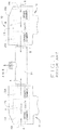
- FIGS. 2A and 2B illustrate this alternating sequence of operation in which FIG. 2A illustrates a first half cycle of operation and FIG. 2B illustrates the second half cycle of operation.
- FIG. 2A during the first half cycle of operation the first compressor head 102 is in the exhaust stroke and exhausts a first gas flow A 1 , while the second compressor head 104 is in the intake stroke and simultaneously intakes a second gas flow B.
- FIG. 2B during the second half cycle of operation the first compressor head 102 is in the intake stroke and intakes gas flow A, while the second compressor head 104 is in the exhaust stroke and simultaneously exhausts gas flow B 1 .
- An output connector 106 is in fluid flow communication with the first compressor head 102 and the second compressor head 104 for permitting a continuous alternating exhaust of a portion of gas flow A or B , designated A 1 or B 1 , generated by the first compressor head 102 or the second compressor head 104, respectively.
- the compressor apparatus 100 includes a shuttling by-pass component 108 that is in fluid flow communication with the first compressor head 102 and the second compressor head 104 for permitting alternating gas flow directly between the first compressor head 102 and the second compressor head 104 during their respective exhaust strokes such that the a portion of the first gas flow A , designated A 2 , is diverted from the first compressor head 102 directly to the second compressor head 104, while a portion of the second gas flow B , designated B 2 , is then diverted from the second compressor head 104 to the first compressor head 102 during the alternating exhaust strokes of the compressor apparatus 100.
- a shuttling by-pass component 108 that is in fluid flow communication with the first compressor head 102 and the second compressor head 104 for permitting alternating gas flow directly between the first compressor head 102 and the second compressor head 104 during their respective exhaust strokes such that the a portion of the first gas flow A , designated A 2 , is diverted from the first compressor head 102 directly to the second compressor head 104, while a portion of the second
- the first half cycle of operation for the compressor apparatus 100 requires that diverted gas flow A 2 from the first compressor head 102 flow into the second compressor head 104 through the shuttling by-pass component 108 in one direction, which completes the first half cycle of operation, and then diverted gas flow B 2 from the second compressor head 104 may flow into the first compressor head 102 in an opposite direction through the shuttling by-pass component 108 during the second half cycle of operation in a continuous alternating sequence of diverted gas flow A 2 and B 2 .
- the flow of diverted gas flows A 2 and B 2 between the first compressor head 102 and the second compressor head 104 follows the same alternating sequence of operation.
- diverted gas flow A 2 is directed from the first compressor head 102 into the second compressor head 104 as the gas flow A 1 exits the output connector 106, while gas flow B simultaneously enters the second compressor head 104.
- the diverted gas flow B 2 now flows from the second compressor head 104 into the first compressor head 102 as the gas flow B 1 exits the output connector 106, while gas flow A simultaneously enters the first compressor head 102.
- the compressor apparatus 100 has been shown to achieve minimum steady flow rates as low as 0.2 liters per minute, which is far below flow rates that are normally achieved by the conventional compressor apparatuses 10 without the by-pass component 108 for diverting a portion of gas flow from one compressor head 102 or 104 to the other compressor head 102 or 104.
- comparison tests have been conducted that show that the flow rate ratio of a maximum flow rate to a minimum flow rate is less than 100 to 1 for conventional compressor apparatuses, while a similar test conducted on the compressor apparatus 100 with the shuttling by-pass component 108 have shown a flow rate ratio of 480 to 1 can be achieved.
- the compressor apparatus 100 can switch the shuttling by-pass component 108 between operational and non-operational states such that an extremely low flow rate can be achieved when the shuttling by-pass component 108 is made operational, while an extremely high flow rate can be achieved when the shuttling by-pass component 108 is made non-operational by the compressor apparatus 100.
- a flow rate ratio of over 800 to 1 has been achieved.
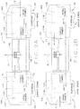
- one embodiment of the compressor apparatus 100 may include the first compressor head 102 and the second compressor head 104 in fluid flow communication with an intake connector 106A for allowing the entry of gas flows A or B during the respective intake strokes and an output connector 106B gas flows A 1 or B 1 during the respective exhaust strokes for delivery to a patient through a ventilator (not shown).
- FIG. 7A and 7B illustrate the various flow pathways through the compressor apparatus 100 in which the first compressor head 102 and the second compressor head 104 operate in alternating intake and exhaust strokes during completion of a full cycle of operation. In the first half cycle of operation undertaken by the compressor apparatus 100 shown in FIG.
- the first compressor head 102 draws in gas flow A into the first compressor head 102 during its respective intake stroke, while the second compressor head 104 simultaneously exhausts out gas flow B 1 through the output connector 107 and diverts a portion of gas flow B 1 , designated gas flow B 2 , through the shuttling by-pass component 108 to the first compressor head 102 during its respective exhaust stroke.
- the second compressor head 104 simultaneously exhausts out gas flow B 1 through the output connector 107 and diverts a portion of gas flow B 1 , designated gas flow B 2 , through the shuttling by-pass component 108 to the first compressor head 102 during its respective exhaust stroke.
- the first compressor head 102 exhausts out gas flow A through the output connector 106 during its respective exhaust stroke while simultaneously diverting a portion of gas flow A 1 , designated gas flow A 2 , through the shuttling by-pass component 108 in a direction opposite to that taken by the diverted gas flow B 2 to the second compressor head 104 as the second compressor head 104 simultaneously draws in gas flow B during its respective intake stroke.
- the compressor apparatus 100 completes a full cycle of operation when the first compressor head 102 and second compressor head 104 have alternately drawn in respective gas flows A or B and then forced out respective gas flows A 1 , A 2 or B 1 , B 2 in alternating fashion through the shuttling by-pass component 108 or the output connector 107 to complete an intake stroke and an exhaust stroke, respectively.
- the first compressor head 102 is substantially similar in structure and operation as the second compressor head 104 with the exception that the first compressor head 102 operates in alternating sequence relative to the second compressor head 104 to complete a full cycle of operation for the compressor apparatus 100.
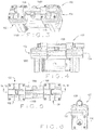
- a motor 116 is provided to operate the first compressor head 102 and the second compressor head 104.
- the motor 116 includes a first rotatable shaft 144 for operating the first compressor head 102 and a second rotatable shaft 146 for operating the second compressor head 104.
- the first compressor head 102 includes a pump casing 124A defining a chamber 134A having an arrangement of a connecting rod 128A engaged to an eccentric mass 130A and counterweight 132A disposed therein.
- the bottom portion of the connecting rod 128A is engaged to the eccentric mass 130A and counterweight 132A, while the top portion of the connecting rod 128A is engaged to a flexible diaphragm 126A through a set screw 162A.
- the bottom portion of the connecting rod 128A is engaged to the rotatable shaft 144 of the motor 116 for moving the connecting rod 128A in an eccentric motion.
- the eccentric movement of the connecting rod 128A by the motor 116 moves the diaphragm 126A in a reciprocating motion.
- An adaptor plate 136A may engage one end of the motor 116 to the pump casing 124A.
- the top portion of the pump casing 124 is engaged to the bottom portion of a compressor head housing 118A, while the top head of the compressor head housing 118A is engaged to a cover head 138A.
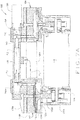
- the compressor head housing 118A includes an inlet 140A that communicates with the intake chamber 110A for permitting the gas flow A to enter therein.
- the intake chamber 110A is in fluid flow communication with the cavity 112A through a plurality of one-way intake valves 120A that permit the inflow of gas into the cavity 112A from the intake chamber 110A, but prevents retrograde gas flow back into the intake chamber 110A.
- the cavity 112A is in fluid flow communication with the exhaust chamber 122A through a plurality of one-way exhaust valves 122A that permit the inflow of gas into the exhaust chamber 114A from the cavity 112A, but prevents retrograde gas flow back into the cavity 112A.
- the cavity 112A is configured to act in concert with the reciprocating diaphragm 126A such that movement of the diaphragm 126A from the cavity 112A during one-half cycle causes gas flow into the cavity 112A from the intake chamber 110A, while movement of the diaphragm 126A toward the cavity 112A during the other half-cycle causes the gas to become compressed and flow from the cavity 112A and into the exhaust chamber 114A such that the compressed gas exits the outlet connector 107 through the outlet 142A of the compressor head housing 118A.
- the second compressor head 104 includes a pump casing 124B defining a chamber 134B having an arrangement of a connecting rod 128B engaged to an eccentric mass 130B and counterweight 132B disposed therein.
- the bottom portion of the connecting rod 128B is engaged to the eccentric mass 130B and counterweight 132B, while the top portion of the connecting rod 128B is engaged to a flexible diaphragm 126B through a set screw 162B.
- the bottom portion of the connecting rod 128B is engaged to the rotatable shaft 144 of the motor 116 for moving the connecting rod 128B in an eccentric motion.
- the eccentric movement of the connecting rod 128B by the motor 116 moves the diaphragm 126B in a reciprocating motion.
- An adaptor plate 136B may engage one end of the motor 116 to the pump casing 124B.
- the top portion of the pump casing 124 is engaged to the bottom portion of a compressor head housing 118B, while the top head of the compressor head housing 118B is engaged to a cover head 138A.
- the compressor head housing 118B includes an inlet 140B that communicates with the intake chamber 110B for permitting the gas flow B to enter therein.
- the intake chamber 110B is in fluid flow communication with the cavity 112B through a plurality of one-way intake valves 120B that permit the inflow of gas into the cavity 112B from the intake chamber 110B, but prevents retrograde gas flow back into the intake chamber 110B.
- the cavity 112B is in fluid flow communication with the exhaust chamber 122B through a plurality of one-way exhaust valves 122B that permit the inflow of gas into the exhaust chamber 114B from the cavity 112B, but prevents retrograde gas flow back into the cavity 112B.
- the cavity 112B is configured to act in concert with the reciprocating diaphragm 126B such that movement of the diaphragm 126B from the cavity 112B during first half cycle causes gas flow into the cavity 112B from the intake chamber 110B, while movement of the diaphragm 126B toward the cavity 112B during the second half cycle causes the gas to become compressed and flow from the cavity 112B and into the exhaust chamber 114B such that the compressed gas exits the outlet connector 106B through the outlet 142B of the compressor head housing 118B.
- the shuttling by-pass component 108 may be an elongated hollow shaft that permits two-way gas flow between the first compressor head 102 and the second compressor head 104 when diverted gas flow A 2 and diverted gas flow B 2 alternately flow between the compressor heads 102 and 104.
- the shuttling by-pass component 108 defines one end that engages a by-pass fitting 148A for coupling the shuttling by-pass component 108 to the cover head 138A of the first compressor head 102 and an opposite end that engages another by-pass fitting 148B for coupling the shuttling by-pass component 108 to the second compressor head 104.
- Sealing elements 158A such as O-rings, provide a fluid-tight seal between the cover head 138A and the by-pass fitting 148A, while sealing elements 158B provide a fluid-tight seal between the cover head 138B and the by-pass fitting 148B.
- the by-pass fitting 148B is operatively engaged to a solenoid 150 through a by-pass seat 152 having a spring 154.
- the spring 154 applies a bias for permitting or preventing fluid flow communication through an orifice 149 formed by the cover head 138B, which is configured to engage the by-pass seat 152 by action of the solenoid 150 which opens and closes the orifice 149 to diverted gas flow A 2 or B 2 .
- the presence of the shuttling by-pass component 108 allows for the compressor apparatus 100 to achieve extremely lower and steadier flow rates in comparison to the flow rates achievable by the conventional compressor apparatus 10 without the by-pass component 108.
- the solenoid 150 opens the by-pass seat 152 during the exhaust stroke of the first compressor head 102 to permit diverted gas flow A 2 to flow from the first compressor head 102 to the second compressor head 104 during first half of cycle of operation.
- the solenoid 150 opens the by-pass seat 152 during the exhaust stroke of the second compressor head 104 to permit diverted gas flow B 2 to flow from the second compressor head 104 to the first compressor head 102 during the second half cycle of operation in order to complete a full cycle of operation by the compressor apparatus 100.
- the orifice size of the shuttling by-pass component 108 may be tailored to achieve a particular flow rate by the compressor apparatus 100 by diverting a specific amount of diverted gas flow from each of the first and second compressor heads 102 and 104.
- the shuttling by-pass component 108 may include a variable orifice (not shown) that provides a variable-sized opening for varying the degree of diverted gas flow A 2 or B 2 permitted to flow through the shuttling by-pass component 108 to the other compressor head 102 or 104 in order to provide flow adjustment capability. In this manner, the amount of diverted gas flow A 2 and B 2 may be adjusted for achieving different degrees of low flow rates by the compressor apparatus 100.
- the shuttling by-pass component 108 may be a screw drive or rotary actuator that may be used to open the orifice 149 as a substitute for the solenoid 150.
- the advantages of incorporating the shuttling by-pass component 108 into the compressor apparatus 100 is that it lowers the potential steady flow rate attainable by the compressor apparatus 100 by diverting a portion of the gas flow from one compressor head during its exhaust cycle to the other compressor head during its intake cycle, and vice versa, as one full cycle of operation of the compressor apparatus 100 is completed.
- the compressor apparatus 100 with the shuttling by-pass component 108 can achieve an extremely low flow rate, such as 0.1 liters per minute, when about 97% (based on an 80+ liters per minute of compressor apparatus 100 capacity) of the exhausted gas flow is diverted to the other compressor head and vice versa. This results in a maximum to minimum flow ratio of 800 to 1.
- the same bypass function may be applied to other compressors with varying capacity to achieve either higher or lower bypass flow rates.
- the shuttling by-pass component 108 may be incorporated into the compressor apparatus 100 having a motor with a fixed power source as an after market modification, which may be used as a means of achieving flow adjustment for the compressor apparatus by varying the amount of gas flow that may be diverted through the shuttling by-pass component 108.
- a compressor apparatus 100 having a first compressor head 102 in fluid flow communication with a second compressor head 104 through an output connector 106 and then engaging a shuttling by-pass component 108 in fluid flow communication between the first compressor head 102 and the second compressor head 104.
- the compressor apparatus 100 is engaged to a ventilator system for providing gas flow to the first compressor head 102 and the second compressor head 104.
- the compressor apparatus 100 is actuated such that the first compressor head 102 generates a first gas flow during a first exhaust stroke of the first compressor head 102 and the second compressor head 104 generates a second gas flow during an alternating second exhaust stroke of the second compressor head 104.
- a portion of the first gas flow is allowed to flow from the first compressor head 102 and into the second compressor head 104 through the shuttling by-pass component 108 during the first exhaust stroke of the first compressor head 102 and then allowing a portion of the alternating second gas flow from the second compressor head 104 to flow through the shuttling by-pass component 108 and into the first compressor head 102 during an alternating second exhaust stroke of the second compressor head 104.
- the first compressor head 102 is engaged to the second compressor head 104 through an output connector 106 to permit exhaust of a gas flow from the first compressor head 102 and the second compressor head 104 in alternating sequence.
- a shuttling by-pass component 108 is engaged between the first compressor head 102 and the second compressor head 104 for establishing fluid flow communication between the first compressor head 102 and the second compressor head 104 to permit a portion of the exhausted gas flow from either the first compressor head 102 or the second compressor head 104 to be diverted to the other respective compressor head 102 or 104. This allows the compressor apparatus 100 to achieve a much lower and steadier flow rate using less power than would otherwise be required by a compressor apparatus 10 without the shuttling by-pass component 108.
- a motor 116 is operatively engaged with the first compressor head 102 and the second compressor head 104 for driving the first compressor head 102 and the second compressor head 104 in alternating sequence.
- the compressor apparatus 100 with the shuttling by-pass component 108 may have applications outside the medical field described herein.
- the compressor apparatus 100 may be used in heating and air conditioning applications as well as refrigeration industries where multi-speed compressors are commonly used.
- the first test was directed to comparing minimum/maximum flow rate ratios exhibited by the standard compressor apparatuses 10 relative to the compressor apparatus 100 and the second test was directed to comparing the variance in flow rate between a standard compressor apparatus 10 and the compressor apparatus 100 with the shuttling by-pass component 108.
- tables 1-5 below provide test results that compare the maximum/minimum flow rate ratio achieved by the compressor apparatus 100 with the shuttling by-pass component 108 (Table 5) with the maximum/minimum flow rate ratios achieved by four prior art standard compressor apparatuses 10 without the shuttling by-pass component 108 (Tables 1-4 ).
- table 1 represents a standard compressor apparatus 10 without the shuttling by-pass component 108 manufactured under the product name GAST (TM) 15D, which exhibits a minimum flow rate of 0.2 liters per minute at a voltage setting of 2 volts and a maximum flow rate of 17.1 liters per minute at a voltage setting of 12 volts.
- TM product name
- Table 2 represents another standard compressor apparatus 10 without the shuttling by-pass component 108 manufactured under the product name T-Squared (TM) , which exhibits a minimum flow rate of 5.1 liters per minute at a voltage setting of 1 volt and a maximum flow rate of 82.3 liters per minute at a voltage setting of 12 volts.
- Table 3 represents another standard compressor apparatus 10 without the shuttling by-pass component 108 manufactured under the product name KNF (TM) , which exhibits a minimum flow rate of 31.1 liters per minute at a voltage setting of 1 volt and a maximum flow rate of 73.8 liters per minute at a voltage setting of 8 volts.
- Table 4 represents yet another standard compressor apparatus 10 without the shuttling by-pass component 108 manufactured under the product name Powerex (TM) , which exhibits a minimum flow rate of 1.3 liters per minute at a voltage setting of 1.7 volts.
- table 5 represents a compressor apparatus 100 with the shuttling by-pass component 108 manufactured by the Applicants, which exhibits a minimum flow rate of 0.1 liters per minute at a voltage setting of 1 volt and a maximum flow rate of 48.1 liters per minute at a voltage setting of 12 volts when the shuttling by-pass component 108 is made operational, while the compressor apparatus 100 exhibits a minimum flow rate of 3.1 liters per minute at a voltage setting of 1 volt and a maximum flow rate of 83.5 liters per minute when the shuttling by-pass component 108 is made non-operational.
- the compressor apparatus 100 with the shuttling by-pass component 108 can operate to make the shuttling by-pass component 108 operational at times to achieve any extremely low flow rate, while making the shuttling by-pass component 108 non-operational at times to achieve an extremely high flow rate.
- Table 6 shows the minimum flow rate, maximum flow rate, and the output flow ratios (maximum flow rate/minimum flow rate) for each of the aforementioned compressor apparatuses 10 without the shuttling by-pass component 108 in comparison with the compressor apparatus 100 having the shuttling by-pass component 108.
- the flow rate ratio of the compressor apparatus 100 with the shuttling by-pass component 108 is almost ten times the flow rate ratio of the closest standard compressor apparatus 10 without the shuttling by-pass component 108.
- the flow rate ratio of the GAST (TM) 15D compressor apparatus 10 without the shuttling by-pass component 108 of table 1 is 85.5 to 1
- the flow rate ratio of the T-Squared (TM) compressor apparatus 10 without the shuttling by-pass component 108 of table 2 is 16.1 to 1
- the flow rate ratio of the KNF (TM) compressor apparatus 10 without the shuttling by-pass component 108 of table 3 is 2.4 to 1
- the flow rate ratio of the Powerex (TM) compressor apparatus 10 without the shuttling by-pass component 108 of table 4 is 61.0 to 1.
- the flow rate ratio of the compressor apparatus 100 when the shuttling by-pass component 108 is made operational is 481 to 1, while an even higher flow rate ratio of 836 to 1 can be achieved when the compressor apparatus 100 switches the shuttling by-pass component 108 between operational mode to achieve a low flow rate of 0.1 liters per minute and the non-operational mode to achieve a high flow rate of 83.5 liters per minute as illustrated in FIG. 5 .
- the test results clearly show that the compressor apparatus 100 with the shuttling by-pass component 108 has a far greater ratio of maximum flow rate to the minimum flow rate, thereby exhibiting much greater range of flow rates than is achievable by the prior art standard compressor apparatuses 10 without the by-pass component 108 under similar operating conditions.
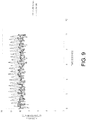
- Table 7 shows the results of the second test for comparing the variance in flow rate, referred to as pulsations, for a standard compressor apparatus 10 as compared with the compressor apparatus 100 having the shuttling by-pass component 108 at the same flow rate of 10 liters per minute. Minimizing the flow rate pulsations or the variance in flow rate by the compressor apparatus when maintaining a particular flow rate is important since a large variance in flow rate can be felt by a patient connected to a ventilator when the compressor apparatus exhibits a high variance in flow rate when maintaining a particular flow rate.
- the standard compressor apparatus 10 without the shuttling by-pass components 108 exhibits a variance in flow rate about 2.5 times larger than the variance in flow rate for the compressor apparatus 100 with the shuttling by-pass component 108.
- Table 7 showing the test data illustrated in the graph of FIG. 9 is set forth below.
Landscapes
- Engineering & Computer Science (AREA)
- Mechanical Engineering (AREA)
- General Engineering & Computer Science (AREA)
- Compressor (AREA)
- Control Of Positive-Displacement Pumps (AREA)
- Structures Of Non-Positive Displacement Pumps (AREA)
- Compressors, Vaccum Pumps And Other Relevant Systems (AREA)
Applications Claiming Priority (2)
| Application Number | Priority Date | Filing Date | Title |
|---|---|---|---|
| US13/229,133 US9022746B2 (en) | 2011-09-09 | 2011-09-09 | Shuttling by-pass compressor apparatus |
| PCT/US2012/049715 WO2013036339A1 (en) | 2011-09-09 | 2012-08-06 | Shuttling by-pass compressor apparatus |
Publications (3)
| Publication Number | Publication Date |
|---|---|
| EP2753391A1 EP2753391A1 (en) | 2014-07-16 |
| EP2753391A4 EP2753391A4 (en) | 2015-07-29 |
| EP2753391B1 true EP2753391B1 (en) | 2016-12-28 |
Family
ID=47829991
Family Applications (1)
| Application Number | Title | Priority Date | Filing Date |
|---|---|---|---|
| EP12830772.5A Active EP2753391B1 (en) | 2011-09-09 | 2012-08-06 | Shuttling by-pass compressor apparatus |
Country Status (10)
| Country | Link |
|---|---|
| US (1) | US9022746B2 (enExample) |
| EP (1) | EP2753391B1 (enExample) |
| JP (1) | JP6055475B2 (enExample) |
| AU (1) | AU2012304846B2 (enExample) |
| BR (1) | BR112014005481B1 (enExample) |
| CA (1) | CA2846166C (enExample) |
| ES (1) | ES2617493T3 (enExample) |
| MX (1) | MX341725B (enExample) |
| RU (1) | RU2593360C2 (enExample) |
| WO (1) | WO2013036339A1 (enExample) |
Families Citing this family (5)
| Publication number | Priority date | Publication date | Assignee | Title |
|---|---|---|---|---|
| TWI683960B (zh) * | 2017-09-15 | 2020-02-01 | 研能科技股份有限公司 | 氣體輸送裝置 |
| US10920758B2 (en) * | 2018-06-29 | 2021-02-16 | Bendix Commercial Vehicle Systems Llc | Hypocycloid compressor |
| JP2023552280A (ja) | 2020-11-09 | 2023-12-15 | ピーディーシー マシンズ インク. | ダイヤフラムコンプレッサのための能動的油噴射システム |
| WO2023080932A1 (en) | 2021-11-08 | 2023-05-11 | Pdc Machines Inc. | High-throughput diaphragm compressor |
| US20250271931A1 (en) * | 2022-05-04 | 2025-08-28 | Hatpx, Inc. | Haptic glove system and manufacture of haptic glove systems |
Family Cites Families (22)
| Publication number | Priority date | Publication date | Assignee | Title |
|---|---|---|---|---|
| US2285215A (en) * | 1939-06-08 | 1942-06-02 | Binks Mfg Co | Fluid compressor |
| GB914343A (en) | 1959-02-06 | 1963-01-02 | Pye Ltd | Electronic time cycled respirator |
| US3101768A (en) * | 1960-09-15 | 1963-08-27 | Curtis Automotive Devices Inc | Resonant intermittent combustion devices |
| DE1453646A1 (de) * | 1964-05-22 | 1969-11-13 | Rau Swf Autozubehoer | Membranpumpe mit engebautem Elektromotor |
| DE2158458A1 (de) * | 1971-11-25 | 1973-05-30 | Langen & Co | Automatisch wirkende entlueftungsvorrichtung |
| US4778356A (en) * | 1985-06-11 | 1988-10-18 | Hicks Cecil T | Diaphragm pump |
| US4842498A (en) * | 1987-01-20 | 1989-06-27 | Thomas Industries, Inc. | Diaphragm compressor |
| US4813979A (en) * | 1988-02-02 | 1989-03-21 | The United States Of America As Represented By The Secretary Of The Air Force | Secondary oxygen purifier for molecular sieve oxygen concentrator |
| DE3919667A1 (de) * | 1989-06-16 | 1990-12-20 | Schneider Druckluft Gmbh | Verfahren zum betreiben einer doppel-kompressoranlage |
| DE9317083U1 (de) * | 1993-11-09 | 1994-01-13 | Knf-Neuberger Gmbh, 79112 Freiburg | Pumpe mit einem Antriebsmotor und einem Gehäuse |
| FR2733688B1 (fr) * | 1995-05-05 | 1997-09-05 | Saime Sarl | Appareil d'assistance respiratoire dont la source de debit de gaz est un compresseur a membranes a actionnement electromagnetique |
| US6062256A (en) * | 1997-02-11 | 2000-05-16 | Engineering Measurements Company | Micro mass flow control apparatus and method |
| US6126410A (en) * | 1998-02-12 | 2000-10-03 | Gast Manufacturing Corporation | Head cover assembly for reciprocating compressor |
| US5968236A (en) * | 1998-02-20 | 1999-10-19 | Bassine; Stuart | Valve free oxygen concentrator |
| RU2146536C1 (ru) * | 1999-04-16 | 2000-03-20 | Специальное конструкторское бюро экспериментального оборудования при Государственном научном центре Российской Федерации "Институт медико-биологических проблем" | Способ подготовки и подачи лечебной газовой смеси и устройство для его осуществления |
| US7320321B2 (en) | 2002-08-26 | 2008-01-22 | Automedx Inc. | Self-contained micromechanical ventilator |
| US7134849B1 (en) * | 2003-04-22 | 2006-11-14 | Trebor International, Inc. | Molded disposable pneumatic pump |
| CA2556695A1 (en) * | 2004-02-26 | 2005-10-06 | Sekos, Inc. | Self-contained micromechanical ventilator |
| US7517199B2 (en) * | 2004-11-17 | 2009-04-14 | Proportion Air Incorporated | Control system for an air operated diaphragm pump |
| US7686870B1 (en) | 2005-12-29 | 2010-03-30 | Inogen, Inc. | Expandable product rate portable gas fractionalization system |
| US8596992B2 (en) * | 2006-08-18 | 2013-12-03 | L•VAD Technology, Inc. | Air supply mechanism for ventricular assist system |
| US20090065007A1 (en) | 2007-09-06 | 2009-03-12 | Wilkinson William R | Oxygen concentrator apparatus and method |
-
2011
- 2011-09-09 US US13/229,133 patent/US9022746B2/en active Active
-
2012
- 2012-08-06 AU AU2012304846A patent/AU2012304846B2/en active Active
- 2012-08-06 ES ES12830772.5T patent/ES2617493T3/es active Active
- 2012-08-06 CA CA2846166A patent/CA2846166C/en active Active
- 2012-08-06 EP EP12830772.5A patent/EP2753391B1/en active Active
- 2012-08-06 RU RU2014113758/14A patent/RU2593360C2/ru active
- 2012-08-06 WO PCT/US2012/049715 patent/WO2013036339A1/en not_active Ceased
- 2012-08-06 JP JP2014529720A patent/JP6055475B2/ja active Active
- 2012-08-06 MX MX2014002678A patent/MX341725B/es active IP Right Grant
- 2012-08-06 BR BR112014005481-9A patent/BR112014005481B1/pt active IP Right Grant
Also Published As
| Publication number | Publication date |
|---|---|
| AU2012304846A1 (en) | 2014-03-06 |
| WO2013036339A1 (en) | 2013-03-14 |
| AU2012304846B2 (en) | 2016-10-27 |
| US9022746B2 (en) | 2015-05-05 |
| ES2617493T3 (es) | 2017-06-19 |
| EP2753391A4 (en) | 2015-07-29 |
| CA2846166C (en) | 2019-06-04 |
| MX341725B (es) | 2016-08-31 |
| JP6055475B2 (ja) | 2016-12-27 |
| BR112014005481A2 (pt) | 2017-03-21 |
| BR112014005481B1 (pt) | 2020-12-08 |
| MX2014002678A (es) | 2014-04-25 |
| US20130064687A1 (en) | 2013-03-14 |
| JP2014526308A (ja) | 2014-10-06 |
| HK1199850A1 (en) | 2015-07-24 |
| CA2846166A1 (en) | 2013-03-14 |
| RU2014113758A (ru) | 2015-10-20 |
| EP2753391A1 (en) | 2014-07-16 |
| RU2593360C2 (ru) | 2016-08-10 |
Similar Documents
| Publication | Publication Date | Title |
|---|---|---|
| EP2753391B1 (en) | Shuttling by-pass compressor apparatus | |
| US4850980A (en) | I.V. pump cassette | |
| US20220412338A1 (en) | Personal air sampling pump assembly | |
| CN100532837C (zh) | 用于手持式口腔护理装置的压缩机 | |
| US20050287007A1 (en) | Foam encased pump | |
| HK1199850B (en) | Shuttling by-pass compressor apparatus | |
| CN220395931U (zh) | 一种自动泄压泵及包含该自动泄压泵的血压计 | |
| CN105723091B (zh) | 用于正排量泵的高压至低压转换阀 | |
| CN114135699B (zh) | 一种单向微滤阀及具有该单向微滤阀的真空设备 | |
| WO2013032587A1 (en) | Multiple valve head compressor apparatus | |
| CN209414118U (zh) | 一种双头隔膜泵 | |
| EP0323216A2 (en) | Reciprocating device and switching mechanism therefor | |
| CN218376766U (zh) | 一种新型泵 | |
| CN211370690U (zh) | 一种电磁隔膜微型水泵装置 | |
| JP4718691B2 (ja) | ダイアフラムポンプ | |
| WO2019186377A1 (en) | Bistable anti-stall valve system | |
| JPS5815632B2 (ja) | 電磁往復動コンプレッサ− | |
| CN114412758A (zh) | 一种脉冲式流体混合隔膜泵及其混合配比设计方法 | |
| RU1789749C (ru) | Мембранный пневмоприводной насос | |
| JP2003293968A (ja) | 気体圧縮機 | |
| JP2006097600A (ja) | 双方向に送流可能なバルブ機構およびそれを用いた容積変動型ポンプ構造 | |
| JPH06177106A (ja) | フィルタ−装置 | |
| JPH0561505B2 (enExample) | ||
| KR20040009842A (ko) | 초박형 산소부화막을 이용한 산소부화공기 공급장치 및이를 가지는 공기조화기와 공기청정기 | |
| PL135534B1 (en) | Pressurized gas operated double-membrane pump |
Legal Events
| Date | Code | Title | Description |
|---|---|---|---|
| PUAI | Public reference made under article 153(3) epc to a published international application that has entered the european phase |
Free format text: ORIGINAL CODE: 0009012 |
|
| 17P | Request for examination filed |
Effective date: 20140320 |
|
| AK | Designated contracting states |
Kind code of ref document: A1 Designated state(s): AL AT BE BG CH CY CZ DE DK EE ES FI FR GB GR HR HU IE IS IT LI LT LU LV MC MK MT NL NO PL PT RO RS SE SI SK SM TR |
|
| DAX | Request for extension of the european patent (deleted) | ||
| REG | Reference to a national code |
Ref country code: HK Ref legal event code: DE Ref document number: 1199850 Country of ref document: HK |
|
| RA4 | Supplementary search report drawn up and despatched (corrected) |
Effective date: 20150626 |
|
| RIC1 | Information provided on ipc code assigned before grant |
Ipc: A61M 16/00 20060101AFI20150622BHEP |
|
| GRAP | Despatch of communication of intention to grant a patent |
Free format text: ORIGINAL CODE: EPIDOSNIGR1 |
|
| INTG | Intention to grant announced |
Effective date: 20160622 |
|
| GRAJ | Information related to disapproval of communication of intention to grant by the applicant or resumption of examination proceedings by the epo deleted |
Free format text: ORIGINAL CODE: EPIDOSDIGR1 |
|
| GRAR | Information related to intention to grant a patent recorded |
Free format text: ORIGINAL CODE: EPIDOSNIGR71 |
|
| GRAS | Grant fee paid |
Free format text: ORIGINAL CODE: EPIDOSNIGR3 |
|
| GRAA | (expected) grant |
Free format text: ORIGINAL CODE: 0009210 |
|
| INTC | Intention to grant announced (deleted) | ||
| AK | Designated contracting states |
Kind code of ref document: B1 Designated state(s): AL AT BE BG CH CY CZ DE DK EE ES FI FR GB GR HR HU IE IS IT LI LT LU LV MC MK MT NL NO PL PT RO RS SE SI SK SM TR |
|
| INTG | Intention to grant announced |
Effective date: 20161121 |
|
| REG | Reference to a national code |
Ref country code: GB Ref legal event code: FG4D |
|
| REG | Reference to a national code |
Ref country code: CH Ref legal event code: EP |
|
| REG | Reference to a national code |
Ref country code: AT Ref legal event code: REF Ref document number: 856770 Country of ref document: AT Kind code of ref document: T Effective date: 20170115 |
|
| REG | Reference to a national code |
Ref country code: IE Ref legal event code: FG4D |
|
| REG | Reference to a national code |
Ref country code: DE Ref legal event code: R096 Ref document number: 602012027200 Country of ref document: DE |
|
| PG25 | Lapsed in a contracting state [announced via postgrant information from national office to epo] |
Ref country code: LV Free format text: LAPSE BECAUSE OF FAILURE TO SUBMIT A TRANSLATION OF THE DESCRIPTION OR TO PAY THE FEE WITHIN THE PRESCRIBED TIME-LIMIT Effective date: 20161228 |
|
| REG | Reference to a national code |
Ref country code: LT Ref legal event code: MG4D |
|
| PG25 | Lapsed in a contracting state [announced via postgrant information from national office to epo] |
Ref country code: SE Free format text: LAPSE BECAUSE OF FAILURE TO SUBMIT A TRANSLATION OF THE DESCRIPTION OR TO PAY THE FEE WITHIN THE PRESCRIBED TIME-LIMIT Effective date: 20161228 Ref country code: GR Free format text: LAPSE BECAUSE OF FAILURE TO SUBMIT A TRANSLATION OF THE DESCRIPTION OR TO PAY THE FEE WITHIN THE PRESCRIBED TIME-LIMIT Effective date: 20170329 Ref country code: LT Free format text: LAPSE BECAUSE OF FAILURE TO SUBMIT A TRANSLATION OF THE DESCRIPTION OR TO PAY THE FEE WITHIN THE PRESCRIBED TIME-LIMIT Effective date: 20161228 Ref country code: NO Free format text: LAPSE BECAUSE OF FAILURE TO SUBMIT A TRANSLATION OF THE DESCRIPTION OR TO PAY THE FEE WITHIN THE PRESCRIBED TIME-LIMIT Effective date: 20170328 |
|
| REG | Reference to a national code |
Ref country code: NL Ref legal event code: MP Effective date: 20161228 |
|
| REG | Reference to a national code |
Ref country code: AT Ref legal event code: MK05 Ref document number: 856770 Country of ref document: AT Kind code of ref document: T Effective date: 20161228 |
|
| PG25 | Lapsed in a contracting state [announced via postgrant information from national office to epo] |
Ref country code: FI Free format text: LAPSE BECAUSE OF FAILURE TO SUBMIT A TRANSLATION OF THE DESCRIPTION OR TO PAY THE FEE WITHIN THE PRESCRIBED TIME-LIMIT Effective date: 20161228 Ref country code: HR Free format text: LAPSE BECAUSE OF FAILURE TO SUBMIT A TRANSLATION OF THE DESCRIPTION OR TO PAY THE FEE WITHIN THE PRESCRIBED TIME-LIMIT Effective date: 20161228 Ref country code: RS Free format text: LAPSE BECAUSE OF FAILURE TO SUBMIT A TRANSLATION OF THE DESCRIPTION OR TO PAY THE FEE WITHIN THE PRESCRIBED TIME-LIMIT Effective date: 20161228 |
|
| REG | Reference to a national code |
Ref country code: ES Ref legal event code: FG2A Ref document number: 2617493 Country of ref document: ES Kind code of ref document: T3 Effective date: 20170619 |
|
| PG25 | Lapsed in a contracting state [announced via postgrant information from national office to epo] |
Ref country code: NL Free format text: LAPSE BECAUSE OF FAILURE TO SUBMIT A TRANSLATION OF THE DESCRIPTION OR TO PAY THE FEE WITHIN THE PRESCRIBED TIME-LIMIT Effective date: 20161228 |
|
| REG | Reference to a national code |
Ref country code: FR Ref legal event code: PLFP Year of fee payment: 6 |
|
| PG25 | Lapsed in a contracting state [announced via postgrant information from national office to epo] |
Ref country code: SK Free format text: LAPSE BECAUSE OF FAILURE TO SUBMIT A TRANSLATION OF THE DESCRIPTION OR TO PAY THE FEE WITHIN THE PRESCRIBED TIME-LIMIT Effective date: 20161228 Ref country code: IS Free format text: LAPSE BECAUSE OF FAILURE TO SUBMIT A TRANSLATION OF THE DESCRIPTION OR TO PAY THE FEE WITHIN THE PRESCRIBED TIME-LIMIT Effective date: 20170428 Ref country code: EE Free format text: LAPSE BECAUSE OF FAILURE TO SUBMIT A TRANSLATION OF THE DESCRIPTION OR TO PAY THE FEE WITHIN THE PRESCRIBED TIME-LIMIT Effective date: 20161228 Ref country code: CZ Free format text: LAPSE BECAUSE OF FAILURE TO SUBMIT A TRANSLATION OF THE DESCRIPTION OR TO PAY THE FEE WITHIN THE PRESCRIBED TIME-LIMIT Effective date: 20161228 Ref country code: RO Free format text: LAPSE BECAUSE OF FAILURE TO SUBMIT A TRANSLATION OF THE DESCRIPTION OR TO PAY THE FEE WITHIN THE PRESCRIBED TIME-LIMIT Effective date: 20161228 |
|
| PG25 | Lapsed in a contracting state [announced via postgrant information from national office to epo] |
Ref country code: SM Free format text: LAPSE BECAUSE OF FAILURE TO SUBMIT A TRANSLATION OF THE DESCRIPTION OR TO PAY THE FEE WITHIN THE PRESCRIBED TIME-LIMIT Effective date: 20161228 Ref country code: BE Free format text: LAPSE BECAUSE OF FAILURE TO SUBMIT A TRANSLATION OF THE DESCRIPTION OR TO PAY THE FEE WITHIN THE PRESCRIBED TIME-LIMIT Effective date: 20161228 Ref country code: AT Free format text: LAPSE BECAUSE OF FAILURE TO SUBMIT A TRANSLATION OF THE DESCRIPTION OR TO PAY THE FEE WITHIN THE PRESCRIBED TIME-LIMIT Effective date: 20161228 Ref country code: BG Free format text: LAPSE BECAUSE OF FAILURE TO SUBMIT A TRANSLATION OF THE DESCRIPTION OR TO PAY THE FEE WITHIN THE PRESCRIBED TIME-LIMIT Effective date: 20170328 Ref country code: PT Free format text: LAPSE BECAUSE OF FAILURE TO SUBMIT A TRANSLATION OF THE DESCRIPTION OR TO PAY THE FEE WITHIN THE PRESCRIBED TIME-LIMIT Effective date: 20170428 Ref country code: PL Free format text: LAPSE BECAUSE OF FAILURE TO SUBMIT A TRANSLATION OF THE DESCRIPTION OR TO PAY THE FEE WITHIN THE PRESCRIBED TIME-LIMIT Effective date: 20161228 |
|
| REG | Reference to a national code |
Ref country code: DE Ref legal event code: R097 Ref document number: 602012027200 Country of ref document: DE |
|
| PLBE | No opposition filed within time limit |
Free format text: ORIGINAL CODE: 0009261 |
|
| STAA | Information on the status of an ep patent application or granted ep patent |
Free format text: STATUS: NO OPPOSITION FILED WITHIN TIME LIMIT |
|
| PG25 | Lapsed in a contracting state [announced via postgrant information from national office to epo] |
Ref country code: DK Free format text: LAPSE BECAUSE OF FAILURE TO SUBMIT A TRANSLATION OF THE DESCRIPTION OR TO PAY THE FEE WITHIN THE PRESCRIBED TIME-LIMIT Effective date: 20161228 |
|
| 26N | No opposition filed |
Effective date: 20170929 |
|
| PG25 | Lapsed in a contracting state [announced via postgrant information from national office to epo] |
Ref country code: SI Free format text: LAPSE BECAUSE OF FAILURE TO SUBMIT A TRANSLATION OF THE DESCRIPTION OR TO PAY THE FEE WITHIN THE PRESCRIBED TIME-LIMIT Effective date: 20161228 |
|
| REG | Reference to a national code |
Ref country code: CH Ref legal event code: PL |
|
| PG25 | Lapsed in a contracting state [announced via postgrant information from national office to epo] |
Ref country code: MC Free format text: LAPSE BECAUSE OF FAILURE TO SUBMIT A TRANSLATION OF THE DESCRIPTION OR TO PAY THE FEE WITHIN THE PRESCRIBED TIME-LIMIT Effective date: 20161228 |
|
| PG25 | Lapsed in a contracting state [announced via postgrant information from national office to epo] |
Ref country code: CH Free format text: LAPSE BECAUSE OF NON-PAYMENT OF DUE FEES Effective date: 20170831 Ref country code: LI Free format text: LAPSE BECAUSE OF NON-PAYMENT OF DUE FEES Effective date: 20170831 |
|
| REG | Reference to a national code |
Ref country code: IE Ref legal event code: MM4A |
|
| PG25 | Lapsed in a contracting state [announced via postgrant information from national office to epo] |
Ref country code: LU Free format text: LAPSE BECAUSE OF NON-PAYMENT OF DUE FEES Effective date: 20170806 |
|
| REG | Reference to a national code |
Ref country code: FR Ref legal event code: PLFP Year of fee payment: 7 |
|
| PG25 | Lapsed in a contracting state [announced via postgrant information from national office to epo] |
Ref country code: IE Free format text: LAPSE BECAUSE OF NON-PAYMENT OF DUE FEES Effective date: 20170806 |
|
| PG25 | Lapsed in a contracting state [announced via postgrant information from national office to epo] |
Ref country code: MT Free format text: LAPSE BECAUSE OF NON-PAYMENT OF DUE FEES Effective date: 20170806 |
|
| PG25 | Lapsed in a contracting state [announced via postgrant information from national office to epo] |
Ref country code: HU Free format text: LAPSE BECAUSE OF FAILURE TO SUBMIT A TRANSLATION OF THE DESCRIPTION OR TO PAY THE FEE WITHIN THE PRESCRIBED TIME-LIMIT; INVALID AB INITIO Effective date: 20120806 |
|
| PG25 | Lapsed in a contracting state [announced via postgrant information from national office to epo] |
Ref country code: CY Free format text: LAPSE BECAUSE OF NON-PAYMENT OF DUE FEES Effective date: 20161228 |
|
| PG25 | Lapsed in a contracting state [announced via postgrant information from national office to epo] |
Ref country code: MK Free format text: LAPSE BECAUSE OF FAILURE TO SUBMIT A TRANSLATION OF THE DESCRIPTION OR TO PAY THE FEE WITHIN THE PRESCRIBED TIME-LIMIT Effective date: 20161228 |
|
| PG25 | Lapsed in a contracting state [announced via postgrant information from national office to epo] |
Ref country code: TR Free format text: LAPSE BECAUSE OF FAILURE TO SUBMIT A TRANSLATION OF THE DESCRIPTION OR TO PAY THE FEE WITHIN THE PRESCRIBED TIME-LIMIT Effective date: 20161228 |
|
| PG25 | Lapsed in a contracting state [announced via postgrant information from national office to epo] |
Ref country code: AL Free format text: LAPSE BECAUSE OF FAILURE TO SUBMIT A TRANSLATION OF THE DESCRIPTION OR TO PAY THE FEE WITHIN THE PRESCRIBED TIME-LIMIT Effective date: 20161228 |
|
| REG | Reference to a national code |
Ref country code: DE Ref legal event code: R082 Ref document number: 602012027200 Country of ref document: DE Representative=s name: MAIWALD GMBH, DE Ref country code: DE Ref legal event code: R082 Ref document number: 602012027200 Country of ref document: DE Representative=s name: MEWBURN ELLIS LLP, DE |
|
| REG | Reference to a national code |
Ref country code: GB Ref legal event code: 732E Free format text: REGISTERED BETWEEN 20240201 AND 20240207 |
|
| REG | Reference to a national code |
Ref country code: DE Ref legal event code: R082 Ref document number: 602012027200 Country of ref document: DE Representative=s name: MEWBURN ELLIS LLP, DE Ref country code: DE Ref legal event code: R081 Ref document number: 602012027200 Country of ref document: DE Owner name: ALLIED MEDICAL, LLC (N.D.GES.D.STAATES DELAWAR, US Free format text: FORMER OWNER: ALLIED HEALTHCARE PRODUCTS, INC., ST. LOUIS, MO., US |
|
| PGFP | Annual fee paid to national office [announced via postgrant information from national office to epo] |
Ref country code: FR Payment date: 20240823 Year of fee payment: 13 |
|
| PGFP | Annual fee paid to national office [announced via postgrant information from national office to epo] |
Ref country code: ES Payment date: 20240902 Year of fee payment: 13 |
|
| PGFP | Annual fee paid to national office [announced via postgrant information from national office to epo] |
Ref country code: IT Payment date: 20240827 Year of fee payment: 13 |
|
| REG | Reference to a national code |
Ref country code: ES Ref legal event code: PC2A Owner name: ALLIED MEDICAL, LLC Effective date: 20241031 |
|
| PGFP | Annual fee paid to national office [announced via postgrant information from national office to epo] |
Ref country code: DE Payment date: 20250819 Year of fee payment: 14 |
|
| PGFP | Annual fee paid to national office [announced via postgrant information from national office to epo] |
Ref country code: GB Payment date: 20250818 Year of fee payment: 14 |