EP2750942B1 - Procédé destiné à avertir le conducteur d'un véhicule d'un risque de basculement, ainsi que dispositif de commande conçu à cet effet - Google Patents
Procédé destiné à avertir le conducteur d'un véhicule d'un risque de basculement, ainsi que dispositif de commande conçu à cet effet Download PDFInfo
- Publication number
- EP2750942B1 EP2750942B1 EP12727599.8A EP12727599A EP2750942B1 EP 2750942 B1 EP2750942 B1 EP 2750942B1 EP 12727599 A EP12727599 A EP 12727599A EP 2750942 B1 EP2750942 B1 EP 2750942B1
- Authority
- EP
- European Patent Office
- Prior art keywords
- vehicle
- lateral acceleration
- control device
- value
- critical
- Prior art date
- Legal status (The legal status is an assumption and is not a legal conclusion. Google has not performed a legal analysis and makes no representation as to the accuracy of the status listed.)
- Active
Links
- 238000000034 method Methods 0.000 title claims description 40
- 230000001133 acceleration Effects 0.000 claims description 126
- 238000012360 testing method Methods 0.000 claims description 12
- 230000009467 reduction Effects 0.000 claims description 7
- 230000003044 adaptive effect Effects 0.000 claims description 4
- 230000001419 dependent effect Effects 0.000 claims description 3
- 230000000007 visual effect Effects 0.000 claims description 3
- 230000003287 optical effect Effects 0.000 description 11
- 230000008901 benefit Effects 0.000 description 5
- 230000006870 function Effects 0.000 description 5
- 230000015572 biosynthetic process Effects 0.000 description 4
- 230000000903 blocking effect Effects 0.000 description 3
- 230000008569 process Effects 0.000 description 3
- 230000001960 triggered effect Effects 0.000 description 3
- 230000006978 adaptation Effects 0.000 description 2
- 230000008859 change Effects 0.000 description 2
- 238000013461 design Methods 0.000 description 2
- 238000001514 detection method Methods 0.000 description 2
- 230000000694 effects Effects 0.000 description 2
- 230000004044 response Effects 0.000 description 2
- 238000013459 approach Methods 0.000 description 1
- 230000033228 biological regulation Effects 0.000 description 1
- 239000003086 colorant Substances 0.000 description 1
- 230000003247 decreasing effect Effects 0.000 description 1
- 238000011161 development Methods 0.000 description 1
- 230000018109 developmental process Effects 0.000 description 1
- 230000004069 differentiation Effects 0.000 description 1
- 238000011156 evaluation Methods 0.000 description 1
- 238000002474 experimental method Methods 0.000 description 1
- 238000013213 extrapolation Methods 0.000 description 1
- 230000012447 hatching Effects 0.000 description 1
- 238000003780 insertion Methods 0.000 description 1
- 230000037431 insertion Effects 0.000 description 1
- 230000007794 irritation Effects 0.000 description 1
- 230000008447 perception Effects 0.000 description 1
- 230000002265 prevention Effects 0.000 description 1
- 230000001105 regulatory effect Effects 0.000 description 1
- 238000012552 review Methods 0.000 description 1
- 230000000087 stabilizing effect Effects 0.000 description 1
- 239000000725 suspension Substances 0.000 description 1
- 230000032258 transport Effects 0.000 description 1
Images


Classifications
-
- B—PERFORMING OPERATIONS; TRANSPORTING
- B60—VEHICLES IN GENERAL
- B60T—VEHICLE BRAKE CONTROL SYSTEMS OR PARTS THEREOF; BRAKE CONTROL SYSTEMS OR PARTS THEREOF, IN GENERAL; ARRANGEMENT OF BRAKING ELEMENTS ON VEHICLES IN GENERAL; PORTABLE DEVICES FOR PREVENTING UNWANTED MOVEMENT OF VEHICLES; VEHICLE MODIFICATIONS TO FACILITATE COOLING OF BRAKES
- B60T8/00—Arrangements for adjusting wheel-braking force to meet varying vehicular or ground-surface conditions, e.g. limiting or varying distribution of braking force
- B60T8/17—Using electrical or electronic regulation means to control braking
- B60T8/1755—Brake regulation specially adapted to control the stability of the vehicle, e.g. taking into account yaw rate or transverse acceleration in a curve
- B60T8/17554—Brake regulation specially adapted to control the stability of the vehicle, e.g. taking into account yaw rate or transverse acceleration in a curve specially adapted for enhancing stability around the vehicles longitudinal axle, i.e. roll-over prevention
-
- B—PERFORMING OPERATIONS; TRANSPORTING
- B60—VEHICLES IN GENERAL
- B60T—VEHICLE BRAKE CONTROL SYSTEMS OR PARTS THEREOF; BRAKE CONTROL SYSTEMS OR PARTS THEREOF, IN GENERAL; ARRANGEMENT OF BRAKING ELEMENTS ON VEHICLES IN GENERAL; PORTABLE DEVICES FOR PREVENTING UNWANTED MOVEMENT OF VEHICLES; VEHICLE MODIFICATIONS TO FACILITATE COOLING OF BRAKES
- B60T13/00—Transmitting braking action from initiating means to ultimate brake actuator with power assistance or drive; Brake systems incorporating such transmitting means, e.g. air-pressure brake systems
- B60T13/10—Transmitting braking action from initiating means to ultimate brake actuator with power assistance or drive; Brake systems incorporating such transmitting means, e.g. air-pressure brake systems with fluid assistance, drive, or release
- B60T13/24—Transmitting braking action from initiating means to ultimate brake actuator with power assistance or drive; Brake systems incorporating such transmitting means, e.g. air-pressure brake systems with fluid assistance, drive, or release the fluid being gaseous
- B60T13/26—Compressed-air systems
- B60T13/38—Brakes applied by springs or weights and released by compressed air
- B60T13/385—Control arrangements therefor
-
- B—PERFORMING OPERATIONS; TRANSPORTING
- B60—VEHICLES IN GENERAL
- B60T—VEHICLE BRAKE CONTROL SYSTEMS OR PARTS THEREOF; BRAKE CONTROL SYSTEMS OR PARTS THEREOF, IN GENERAL; ARRANGEMENT OF BRAKING ELEMENTS ON VEHICLES IN GENERAL; PORTABLE DEVICES FOR PREVENTING UNWANTED MOVEMENT OF VEHICLES; VEHICLE MODIFICATIONS TO FACILITATE COOLING OF BRAKES
- B60T13/00—Transmitting braking action from initiating means to ultimate brake actuator with power assistance or drive; Brake systems incorporating such transmitting means, e.g. air-pressure brake systems
- B60T13/10—Transmitting braking action from initiating means to ultimate brake actuator with power assistance or drive; Brake systems incorporating such transmitting means, e.g. air-pressure brake systems with fluid assistance, drive, or release
- B60T13/66—Electrical control in fluid-pressure brake systems
- B60T13/662—Electrical control in fluid-pressure brake systems characterised by specified functions of the control system components
-
- B—PERFORMING OPERATIONS; TRANSPORTING
- B60—VEHICLES IN GENERAL
- B60T—VEHICLE BRAKE CONTROL SYSTEMS OR PARTS THEREOF; BRAKE CONTROL SYSTEMS OR PARTS THEREOF, IN GENERAL; ARRANGEMENT OF BRAKING ELEMENTS ON VEHICLES IN GENERAL; PORTABLE DEVICES FOR PREVENTING UNWANTED MOVEMENT OF VEHICLES; VEHICLE MODIFICATIONS TO FACILITATE COOLING OF BRAKES
- B60T13/00—Transmitting braking action from initiating means to ultimate brake actuator with power assistance or drive; Brake systems incorporating such transmitting means, e.g. air-pressure brake systems
- B60T13/10—Transmitting braking action from initiating means to ultimate brake actuator with power assistance or drive; Brake systems incorporating such transmitting means, e.g. air-pressure brake systems with fluid assistance, drive, or release
- B60T13/66—Electrical control in fluid-pressure brake systems
- B60T13/68—Electrical control in fluid-pressure brake systems by electrically-controlled valves
- B60T13/683—Electrical control in fluid-pressure brake systems by electrically-controlled valves in pneumatic systems or parts thereof
-
- B—PERFORMING OPERATIONS; TRANSPORTING
- B60—VEHICLES IN GENERAL
- B60T—VEHICLE BRAKE CONTROL SYSTEMS OR PARTS THEREOF; BRAKE CONTROL SYSTEMS OR PARTS THEREOF, IN GENERAL; ARRANGEMENT OF BRAKING ELEMENTS ON VEHICLES IN GENERAL; PORTABLE DEVICES FOR PREVENTING UNWANTED MOVEMENT OF VEHICLES; VEHICLE MODIFICATIONS TO FACILITATE COOLING OF BRAKES
- B60T17/00—Component parts, details, or accessories of power brake systems not covered by groups B60T8/00, B60T13/00 or B60T15/00, or presenting other characteristic features
- B60T17/18—Safety devices; Monitoring
- B60T17/22—Devices for monitoring or checking brake systems; Signal devices
- B60T17/221—Procedure or apparatus for checking or keeping in a correct functioning condition of brake systems
-
- B—PERFORMING OPERATIONS; TRANSPORTING
- B60—VEHICLES IN GENERAL
- B60T—VEHICLE BRAKE CONTROL SYSTEMS OR PARTS THEREOF; BRAKE CONTROL SYSTEMS OR PARTS THEREOF, IN GENERAL; ARRANGEMENT OF BRAKING ELEMENTS ON VEHICLES IN GENERAL; PORTABLE DEVICES FOR PREVENTING UNWANTED MOVEMENT OF VEHICLES; VEHICLE MODIFICATIONS TO FACILITATE COOLING OF BRAKES
- B60T7/00—Brake-action initiating means
- B60T7/12—Brake-action initiating means for automatic initiation; for initiation not subject to will of driver or passenger
-
- B—PERFORMING OPERATIONS; TRANSPORTING
- B60—VEHICLES IN GENERAL
- B60T—VEHICLE BRAKE CONTROL SYSTEMS OR PARTS THEREOF; BRAKE CONTROL SYSTEMS OR PARTS THEREOF, IN GENERAL; ARRANGEMENT OF BRAKING ELEMENTS ON VEHICLES IN GENERAL; PORTABLE DEVICES FOR PREVENTING UNWANTED MOVEMENT OF VEHICLES; VEHICLE MODIFICATIONS TO FACILITATE COOLING OF BRAKES
- B60T8/00—Arrangements for adjusting wheel-braking force to meet varying vehicular or ground-surface conditions, e.g. limiting or varying distribution of braking force
- B60T8/24—Arrangements for adjusting wheel-braking force to meet varying vehicular or ground-surface conditions, e.g. limiting or varying distribution of braking force responsive to vehicle inclination or change of direction, e.g. negotiating bends
- B60T8/241—Lateral vehicle inclination
- B60T8/243—Lateral vehicle inclination for roll-over protection
Definitions
- the invention relates to a method for warning the driver of a vehicle of an impending overturning of the vehicle about its longitudinal axis according to the preamble of claim 1.
- the invention further relates to a control device having a program with program code means according to claim 9.
- the invention relates to the field of commercial vehicles, namely towing vehicles and trailers for road traffic.
- a generic method for warning the driver of a vehicle is from the US Pat. No. 6,498,976 B1 known. It is provided that the driver is warned of an imminent tipping over of the vehicle when cornering, so that he z. B. by decelerating the vehicle speed can be adjusted so that a safe driving condition is maintained.
- the known methods and devices are designed such that the warning signal is generated when the instantaneous lateral acceleration of the vehicle exceeds a fixed threshold.
- the determination of the threshold is associated with an effort in practice, especially when it comes to many different types of vehicles. To improve this situation will be in the US Pat. No. 6,498,976 B1 proposed to make the threshold variable in that it is made dependent on the vehicle mass. If the vehicle mass is known, then a suitable threshold value can be taken from a table.
- EP 1 104 732 A2 discloses a method for preventing the tipping over of a vehicle, in particular a utility vehicle, proposed.
- the lateral acceleration of the vehicle is detected by means of sensors, the air spring bellows pressures and simultaneously with a lateral acceleration sensor or wheel speed sensors. From the pair of values thus determined for a specific load, a limit acceleration is calculated in which the air spring pressure of the inside wheel of the curve has dropped to atmospheric pressure. If, during the journey, the current lateral acceleration of the vehicle should reach approximately 75% of the limit acceleration, the speed of the vehicle is reduced by a driver warning, an automatic engine throttling or an automatic braking.
- DE 196 02 879 C1 discloses a vehicle dynamics control method and a corresponding device for motor vehicles, in particular for commercial vehicles, which are provided with an ABS system in which the brake pressure in blocking in the sense of preventing excessive wheel slip is varied, characterized in that a decrease the tilting stability of the vehicle is determined during cornering on the basis of an insertion of an ABS control intervention.
- DE 199 07 633 A1 discloses a method for stabilizing a vehicle, preferably for avoiding the tipping over of a vehicle about a vehicle axle oriented in the longitudinal direction of the vehicle.
- a variable describing the lateral dynamics of the vehicle is determined. This quantity is compared with at least one characteristic value, in particular a threshold, for this quantity.
- the speed of the vehicle is reduced to a predeterminable speed value at least by braking interventions on at least one wheel and / or by engine interventions and / or by retarder interventions or maintained at a predetermined speed value.
- the invention is therefore based on the object of specifying a more precise method for warning the driver of a vehicle of an impending overturning of the vehicle about its longitudinal axis, in which the aforementioned expense for the determination of the threshold value or the table values is avoided or at least significantly reduced. Furthermore, a suitable control device should be specified.
- the object is achieved by a method for warning the driver of a vehicle of an imminent tipping over of the vehicle about its longitudinal axis, wherein a control device detects the instantaneous lateral acceleration of the vehicle and outputs depending on a warning signal in the event of impending tipping, wherein the control device, the warning signal in addition depending is dependent on at least one of the control device during driving of the vehicle determined tilt-critical lateral acceleration value, which is a measure of the lateral acceleration of the vehicle, in which the vehicle would actually tip over its longitudinal axis, the tilt-critical lateral acceleration value based on the vehicle behavior when cornering by the controller automatically is determined.
- the method has the advantage that not depending on the vehicle design and loading of the vehicle, a specific threshold or table entry for generating the warning of the driver must be entered and previously determined by experiments. Compared to fixed threshold procedures, the invention allows a driver's realistic alert adapted to current conditions. It is avoided that the warning is already generated unnecessarily early, ie at relatively low lateral acceleration.
- the method can therefore be used in a variety of vehicle types, such as tractors, semi-trailers, drawbar trailers, even with different structures such as container transports, closed box bodies or dump trucks.
- the gauge of the vehicle is a determining factor of the vehicle type.
- the invention can be used without special adjustments in vehicles with arbitrary gauges.
- the tilt-critical lateral acceleration value is a vehicle-type and vehicle load-specific measure of the lateral acceleration of the vehicle, in which the vehicle would actually overturn about its longitudinal axis.
- the vehicle may be a towing vehicle or a trailer vehicle, such. B. a semi-trailer or a drawbar trailer.
- the control device is set up to determine a measure of the instantaneous lateral acceleration of the vehicle.
- the control device z. B. evaluate the signal of a lateral acceleration sensor or computationally determine a measure of the lateral acceleration due to other input signals, z. B. by evaluating the rotational speeds of the wheels of the vehicle on the left and the right side of the vehicle. Corresponding rotational speed differences between the left and the right side of the vehicle are also a measure of the lateral acceleration of the vehicle taking into account the gauge.
- the tilt-critical lateral acceleration value can be determined in different ways and stored in the control device. So z. B. the control device the Radaufstandskraft be detected by wheels on the ground, z. Example by means of a force sensor or by evaluation of the bellows pressure of bellows, when the vehicle with an air suspension Is provided. When cornering it is checked how much the inside wheels of the vehicle are relieved. From the determined relief value and the transverse acceleration value detected in the process, the tilt-critical lateral acceleration value can be determined by extrapolation. The tilt-critical lateral acceleration value corresponds to the state of at least almost completely relieved inside wheels.
- the wheel rotation speed of one or more inside wheels of the vehicle can be evaluated by the control device in order to determine the tilt-critical lateral acceleration value based on the vehicle behavior when cornering.
- z. B. a test braking with low brake pressure can be performed.
- the control device may be part of an electronically controlled braking system of the vehicle or a separate control device.
- the control device can be designed in particular as an electronic control device.
- the tilt-critical lateral acceleration value is adapted adaptively by the control device starting from an initial value in the course of one or more cornering of the vehicle by evaluating at least one further input variable detected by the control device.
- the tilt-critical lateral acceleration value in the course of one or more cornering of the Vehicle increases.
- a reduction of the tilt-critical lateral acceleration value is therefore not provided.
- the tilt-critical lateral acceleration value can only be changed in one direction, in which the generation of the warning signal in each driving state is generated sufficiently early before a real overturning of the vehicle.
- a test braking is triggered on at least one inner wheel of the control device during cornering, in which the at least one inside wheel is subjected to a low braking force in relation to the maximum braking force, and the RadFEs at least one of the test braking applied wheel is used for the adaptive adaptation of the tilt-critical lateral acceleration value.
- Another advantage is that the method according to the invention can be easily combined with a method for avoiding tipping over of a vehicle about its longitudinal axis, such as, for example, a vehicle.
- B. off DE 100 17 045 A1 is known, in which by an active braking intervention, which is automatically triggered by the control device, the vehicle speed is reduced in critical situations.
- control device is therefore additionally arranged to execute a method for avoiding tipping over of a vehicle about its longitudinal axis, in which at imminent danger of tipping automatically braking is initiated by at least one wheel of the vehicle automatically by the controller Braking force is applied.
- the control device stores the fact that a characteristic reduction of the wheel rotational speed has occurred as a result of the test braking and then inhibits further increases in the tilt-critical lateral acceleration value, even if no further reduction in the characteristic of the lateral critical acceleration value occurs during further test braking with a lateral acceleration RadFWteil is detected.
- the storage and prevention of the increase of the tilt-critical lateral acceleration value can be permanent or temporary, for. B. until the end of the ride done.
- the aforementioned step value, by which the tilt-critical lateral acceleration value is respectively increased, may be a predetermined fixed value or a variable value. It is advantageous z. B. the use of a decaying in the course of the ride level value, z. For example, after a decaying exponential function or a decaying hyperbola function. So z.
- the step value may be decreased from an initial value each time the tilt-critical lateral acceleration value is increased for the next increase in the tilt-critical lateral acceleration value, e.g. B. by a predetermined percentage. This allows a particularly sensitive adaptive adaptation to the lateral acceleration of the vehicle, in which the vehicle would actually overturn about its longitudinal axis.
- the warning signal is output as a visual and / or acoustic signal.
- the acoustic signal can z. B. be a warning sound or a warning in the form of a voice output.
- a warning light are turned on or warnings are issued on a display of the vehicle.
- the warning signal is generated when the instantaneous lateral acceleration with respect to the tilt-critical lateral acceleration value exceeds a limit value.
- instantaneous lateral acceleration with respect to the tilt-critical lateral acceleration value z.
- the quotient of the instantaneous lateral acceleration and the tilt-critical lateral acceleration value or the difference between the instantaneous lateral acceleration and the tilt-critical lateral acceleration value can be used and compared in magnitude with the limit value.
- the current lateral acceleration of the vehicle relative to the tilt-critical lateral acceleration value is visually displayed as a warning signal. This allows a particularly simple and intuitive detection of the current risk of the vehicle tipping over by the driver. The driver can react to this particularly intuitively and adjust the speed of the vehicle accordingly.
- the instantaneous lateral acceleration of the vehicle is represented in terms of the tilt-critical lateral acceleration value in the manner of an artificial horizon.
- the artificial horizon can z. B. on the basis of a graphic animation on a graphics-enabled display or, if an optical representation is to be generated with less effort, by light bar displays.
- the reproduced with the artificial horizon angle of inclination of the vehicle body relative to the horizontal can thereby directly from the Quotients of the instantaneous lateral acceleration based on the tilt-critical lateral acceleration value or be determined from the difference between the two values.
- an additional visual and / or audible warning are issued, for. For example, by issuing red warning signals on the display or by warning tones.
- the control device determines a first tilt-critical lateral acceleration value, which is a measure of the lateral acceleration of the vehicle in left-hander curves, in which the vehicle would actually tip over its longitudinal axis in the case of left-hander curves.
- the controller determines a second lateral critical acceleration value that is a measure of the lateral acceleration of the vehicle at which the vehicle would actually overturn about its longitudinal axis in right-hand turns.
- the warning of the driver or the optical and acoustic outputs are determined by the controller then depending on whether the vehicle is driving a right turn or a left turn, using either the first tilt critical lateral acceleration value or the second tilt critical lateral acceleration value.
- This allows additional differentiation in the generation of the warning in asymmetrically built vehicles or unbalanced load of the vehicle. So z. B. a trailer only on one side, z. B. right or left, be heavily loaded, so that depending on the direction of the curve different tilt-critical lateral acceleration values may be present.
- control device having a program with program code means which is set up to execute a method of the previously described type when the program is executed on a computer of the control device.
- the Control device can, for. B. be designed as electronic control device with a computer, for. B. as part of an electronically controlled braking system of the vehicle.
- FIG. 1 is a located on a road 1 in a left turn vehicle 2, 3, here consisting of tractor unit 2 and semitrailer 3, shown in plan view.
- the semi-trailer 3 has a brake system of pneumatic type, which is acted upon by the tractor 2 due to a brake pedal operation by the driver or due to certain control and regulating functions in the vehicle with brake pressure.
- the tractor unit 2 is connected via electric and pneumatic lines 11 to the trailer 3.
- the tractor unit 2 and the semi-trailer 3 are rotatably connected to each other at a pivot point 10.
- the brake system of the trailer 3 has z. B. electrically actuated components such. B. ABS brake pressure modulators or purely electrically actuated brake actuators.
- the brake modulators or brake actuators are controlled by a control device 13 in the form of an electronic control unit.
- the control unit 13 and the brake modulators or brake actuators are supplied via electrical and pneumatic lines 12 with electrical energy and the pressure medium or the braking energy.
- the electronic control unit 13 are also still rotational speeds v 4 , v 5 , v 7 , v 8 of the wheels 4, 5, 7, 8 supplied in a manner known in antilock braking ago.
- the electronic control unit 13 carries out a series of control and regulation tasks in the semitrailer 3.
- One of these control tasks is to detect the danger of the vehicle 2, 3 tipping over about its longitudinal axis and to prevent it by targeted braking intervention, as shown in FIG. 2 is exemplified by means of a flow chart.
- the method according to FIG. 2 begins with a block 20.
- the rotational speeds v 4 , v 5 , v 7 , v 8 of the wheels 4, 5, 7, 8 are read.
- a first lateral acceleration signal a q, 1 is determined from the rotational speeds v 4 , v 7
- a q 2 1 2 • S • v 5 - v 8th • v 5 + v 8th
- the quantity S represents the track width of the vehicle.
- the lateral acceleration signals a q, 1 , a q, 2 are each a measure of the instantaneous lateral acceleration of the vehicle 2, 3.
- the lateral acceleration signals a q, 1 , a q, 2 are described below Process sequence used in common instead of a single, for example, from the rotational speeds v 4 , v 5 , v 7 , v 8 determined lateral acceleration signal.
- the method is less susceptible to signal interference, different tire diameters and the like, so that a faulty response of the method can be avoided.
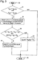
- a branching block 23 is then checked whether the brake system already in an earlier execution of the in the FIG. 2 . 3 and 4 shown sequence with a braking force F 2 was applied to avoid tipping over. If this is the case, bypassing the below using the FIG. 3 Subroutine block 26, which is explained in more detail below and serves, inter alia, to detect the danger of tipping over, branches directly to block 24, where it is checked whether the danger of tipping over no longer exists.
- both the first lateral acceleration signal a q, 1 and the second lateral acceleration signal a q, 2 exceed a predetermined for a response of the method lateral acceleration threshold a q, crit .
- the lateral acceleration threshold a q crit corresponds to the tilt-critical lateral acceleration value. If this is the case, in a block 32, the wheels 4, 5, 6, 7, 8, 9 of the trailer 3 with a relatively low braking force F 1 applied.
- the braking force F 1 is set such that only a relatively small, hardly noticeable to the driver braking effect occurs and in particular on roads with a relatively high coefficient of friction no blocking of wheels occurs, if there is no risk of tipping over.
- a brake pressure of about 1 to 2 bar is applied to apply the braking force F 1 .
- the ABS slip signals for the wheels 7, 8 are disabled to avoid starting the anti-skid function due to high slip.
- a control based on acceleration signals is still possible, so that possible damage to the tires can be avoided.
- a subsequent branch block 33 is checked after the decay of sufficient settling time of the brake pressure buildup or the structure of the braking force F 1 , whether the rotational speeds v 7 , v 8 of the inside wheels 7, 8 are characteristically lower than the rotational speeds v 4 , v 5 of the outer wheels 4, 5, while the rotational speeds of the outer wheels remain substantially unchanged.
- the former is checked by comparing the sum of the speeds of rotation v 7 , v 5 of the outside wheels with the sum of the speeds v 4 , v 5 of the inside wheels evaluated by a factor K 1 , the latter being based on the sum of the decelerations of the wheels 4, 5, ie, the first time derivative of the associated rotational speeds v 4 , v 5 , checked.
- the outside wheels 4, 5, 6 having the better frictional connection between the roadway and the tire are subjected to a high braking force F 2 in relation to the braking force F 1 .
- the braking force F 2 is dimensioned such that by reducing the vehicle speed, the lateral acceleration and thus the risk of tipping is reduced immediately.
- a blocking of the applied with the braking force F 2 wheels is prevented by the anti-lock braking system.
- the inside wheels 7, 8, 9 are further acted upon by the low braking force F 1 .
- a pressure of 4 to 8 bar is preferably controlled in a conventional compressed air-controlled brake system.
- the subroutine then ends with a block 36.
- Verified condition is to be answered in the FIG. 2 in a subsequent branch block 24 checks whether both the first lateral acceleration signal a q, 1 and the second lateral acceleration signal a q, 2, the lateral acceleration threshold a q, crit below. If this is the case, there is no danger of tipping over, and in a subsequent block 25, the braking forces F 1 , F 2 can be canceled and the ABS slip signals locked in the block 32 can be released again. Otherwise, bypassing the block 25 branches directly to a block 27, with which the process ends.
- the operation of the invention and in particular the use of the lateral acceleration signals a q, 1 , a q, 2 can be illustrated as follows.
- equations [1] and [2] this leads to a rapid increase in the first and the second lateral acceleration signals a q, 1 , a q, 2 .
- the replacement of the inside wheels 7, 8, 9, z In the opposite case, the replacement of the inside wheels 7, 8, 9, z.
- the calculated lateral acceleration signals a q, 1 , a q, 2 decrease rapidly. Because of the rapid change in the lateral acceleration signals, the test braking, which brings the low-wheel-laden or in-air wheels at the risk of tipping over, can be used for a reliable detection of the relaunch of the wheels or the termination of the tipping over because the inside wheels then start again due to the increasing wheel load despite the braking effect caused by the braking force F 1 , resulting in a characteristic increase in the rotational speeds v 7 , v 8 of these wheels.
- branching is made to block 36, at which the method ends.
- the method is also suitable for vehicles with only one axle or with only one axle equipped with rotational speed sensors.
- the FIG. 4 shows a method for warning the driver of the vehicle 2, 3 using the current lateral acceleration of the vehicle and the tilt-critical lateral acceleration value.
- the method begins with a block 40.
- a risk value H is determined as the quotient of the instantaneous lateral acceleration a q and the tilt-critical lateral acceleration value a q, Krit , for which the block according to FIG. 3 certain lateral acceleration threshold is used.
- a current lateral acceleration a q z. B the mean of a q, 1 and a q, 2 are used.
- an optical output of the Risk value H in the manner of an artificial horizon as explained below.
- the risk value H can be z. B. are converted directly proportional to an inclination of the artificial horizon relative to the horizontal.
- a branch block 43 it is checked whether the risk value H exceeds a risk limit H limit. If so, a branch is made to an output block 44 where the issue of a warning tone is triggered. The method then ends in a block 45.
- the output of the warning can z. Example, then take place when the instantaneous lateral acceleration of the vehicle reaches or exceeds 95% of the tilt-critical lateral acceleration value in terms of amount.
- the driver is thus not unnecessarily warned of an imminent danger of tipping over of the vehicle. Especially with unloaded vehicles there is no risk of tipping over, so that unnecessary warnings are avoided and thus irritation of the driver can be avoided.
- the FIG. 5 schematically shows an optical representation of the instantaneous lateral acceleration of the vehicle with respect to the tilt-critical lateral acceleration value in the manner of an artificial horizon in a first embodiment. It can, for. B. on a graphic display of the vehicle, an animation of an artificial horizon with a display area 60 are shown. Within the display area 60, a horizontal bar arrangement 61 indicates the horizontal. A skew-variable line 62 indicates an artificial horizon as would correspond to the perception of the driver of the vehicle with the vehicle tilted accordingly.
- the FIG. 5 shows an example of the representation at a left turn.
- the angle between the line 62 and the beam assembly 61 is a measure of the instantaneous lateral acceleration of the vehicle, either for this purpose, the instantaneous lateral acceleration can be used directly, or related to the tilt-critical lateral acceleration value.
- Warning markings 63, 64 indicate where the tilt-critical value for the lateral acceleration located. If the line 62 reaches one of the warning markings 63, 64, then the vehicle is in a dangerous state, in which it threatens to tip over about the longitudinal axis.
- the warning marks 63, 64 can be displayed at the optical output of the artificial horizon 60 by the control device at a desired location, which corresponds to the tilt-critical lateral acceleration value, d. H. numerically calculated from this.
- the line 62 is displayed directly in accordance with the instantaneous lateral acceleration, whereby the reference to the tilt-critical lateral acceleration value based on the warning marks 63, 64 results due to the optical output.
- no quotient formation or difference formation is required from the instantaneous lateral acceleration and the tilt-critical lateral acceleration value.
- the warning marks 63, 64 are displayed at fixed positions. In this case, it is advantageous to determine the line 62 with respect to its inclination on the basis of a mathematical reference between the instantaneous lateral acceleration and the tilt-critical lateral acceleration value, for. B. by the mentioned quotient formation or difference formation.
- FIG. 6 shows a second embodiment of the optical representation of the instantaneous lateral acceleration with respect to the tilt-critical lateral acceleration value in the manner of an artificial horizon.
- a block 70 an output display consisting of three juxtaposed bar displays 71, 72, 73, z. B. formed by light emitting diodes.
- Each of the bar displays 71, 72, 73 may be formed with blocks of different colored light emitting diodes, z. B. in the lower area with a block 76 green light emitting diodes, in the middle with a block 75 yellow LEDs and in the upper part with a block 74 red light emitting diodes.
- the colors signal the safety or the risk of the driving condition, whereby green stands for a low risk and red for a high risk.
- the type of display is explained on the basis of a left turn of the vehicle (block 77), a straight run (block 78) and a right turn (block 79).
- Illuminated LEDs are characterized by hatching.
- the arrows shown below the blocks are for illustrative purposes only and are not part of the optical representation of the dispensing display.
- the left-hand curve it can be seen that two of the green LEDs light up from the left-hand bar display 71, the uppermost green LED from the middle bar display 72 and the uppermost green LED from the right-hand bar display 73, as well as all yellow light-emitting diodes.
Landscapes
- Engineering & Computer Science (AREA)
- Transportation (AREA)
- Mechanical Engineering (AREA)
- Regulating Braking Force (AREA)
- Emergency Alarm Devices (AREA)
Claims (8)
- Procédé d'avertissement du conducteur d'un véhicule (2, 3) de la menace d'un basculement du véhicule (2, 3) autour de son axe longitudinal, dans lequel un dispositif de commande (13) saisit l'accélération transversale instantanée (aq) du véhicule (2, 3) et délivre à partir de ce dernier un signal d'avertissement en cas de risque de basculement,
le dispositif de commande (13) faisant de plus dépendre le signal d'avertissement d'au moins une valeur d'accélération transversale (aq,Krit) critique de basculement déterminée par le dispositif de commande (13) pendant que le véhicule (2, 3) est en circulation, cette valeur étant une mesure de l'accélération transversale du véhicule (2, 3) pour laquelle le véhicule (2, 3) aurait effectivement basculé autour de son axe longitudinal,
la valeur critique de basculement (aq,Krit) de l'accélération transversale étant déterminée automatiquement par le dispositif de commande (13) sur la base du comportement du véhicule se déplaçant en virage,
caractérisé en ce que
pendant un déplacement en virage, un freinage de test à faible pression de freinage au cours duquel une force de freinage plus petite que la plus grande force de freinage possible est appliquée sur une ou plusieurs roues (7, 8, 9) situées à l'intérieur de virage est déclenché par le dispositif de commande (13) sur la ou les roues (7, 8, 9) situées à l'intérieur du virage, l'évolution de la vitesse de rotation de la ou des roues (7, 8, 9) sur lesquelles le freinage de test a été appliqué intervenant dans l'adaptation adaptative de la valeur critique de basculement (aq,Krit) de l'accélération transversale. - Procédé selon la revendication 1, caractérisé en ce que la valeur critique de basculement (aq,Krit) de l'accélération transversale est adaptée de manière adaptative par le dispositif de commande (13) sur la base d'une valeur initiale au cours d'un ou de plusieurs passages en virage du véhicule (2, 3), par évaluation d'au moins une autre grandeur d'entrée saisie par le dispositif de commande (13).
- Procédé selon la revendication 2, caractérisé en ce que la valeur critique de basculement (aq,Krit) de l'accélération transversale est augmentée dans un ou plusieurs passages en virage du véhicule (2, 3).
- Procédé selon la revendication 1, caractérisé en ce que la valeur critique de basculement (aq,Krit) de l'accélération transversale est augmentée d'une valeur de pas (K3) s'il est constaté que le freinage de test ne conduit pas à une diminution caractéristique de la vitesse de rotation d'au moins une des roues (7, 8, 9) freinées à une faible pression de freinage.
- Procédé selon l'une des revendications précédentes, caractérisé en ce que le signal d'avertissement est délivré sous la forme d'un signal optique et/ou acoustique.
- Procédé selon l'une des revendications précédentes, caractérisé en ce que le signal d'avertissement représente optiquement l'accélération transversale instantanée (aq) du véhicule (2, 3) par rapport à la valeur critique de basculement (aq,Krit) de l'accélération transversale.
- Procédé selon la revendication 6, caractérisé en ce que l'accélération transversale instantanée (aq) du véhicule (2, 3) est représentée par rapport à la valeur critique de basculement (aq,Krit) de l'accélération transversale sous la forme d'un horizon artificiel.
- Dispositif de commande (13) doté d'un programme présentant des moyens de code de programme conçus pour mettre en oeuvre un procédé selon l'une des revendications précédentes lorsque le programme est exécuté sur un calculateur du dispositif de commande (13).
Applications Claiming Priority (2)
| Application Number | Priority Date | Filing Date | Title |
|---|---|---|---|
| DE102011111862A DE102011111862A1 (de) | 2011-08-31 | 2011-08-31 | Verfahren zur Warnung des Fahrers eines Fahrzeuges vor einem drohenden Umkippen und Steuerungseinrichtung dafür |
| PCT/EP2012/002494 WO2013029703A2 (fr) | 2011-08-31 | 2012-06-13 | Procédé destiné à avertir le conducteur d'un véhicule d'un risque de basculement, ainsi que dispositif de commande conçu à cet effet |
Publications (3)
| Publication Number | Publication Date |
|---|---|
| EP2750942A2 EP2750942A2 (fr) | 2014-07-09 |
| EP2750942B1 true EP2750942B1 (fr) | 2017-12-13 |
| EP2750942B2 EP2750942B2 (fr) | 2022-12-21 |
Family
ID=46298362
Family Applications (1)
| Application Number | Title | Priority Date | Filing Date |
|---|---|---|---|
| EP12727599.8A Active EP2750942B2 (fr) | 2011-08-31 | 2012-06-13 | Procédé destiné à avertir le conducteur d'un véhicule d'un risque de basculement, ainsi que dispositif de commande conçu à cet effet |
Country Status (6)
| Country | Link |
|---|---|
| US (1) | US9969370B2 (fr) |
| EP (1) | EP2750942B2 (fr) |
| CN (1) | CN103687765A (fr) |
| DE (1) | DE102011111862A1 (fr) |
| ES (1) | ES2657545T5 (fr) |
| WO (1) | WO2013029703A2 (fr) |
Families Citing this family (12)
| Publication number | Priority date | Publication date | Assignee | Title |
|---|---|---|---|---|
| US9260096B2 (en) * | 2011-02-22 | 2016-02-16 | Nissin Kogyo Co., Ltd. | Brake fluid pressure control apparatus for vehicle |
| DE102015013761A1 (de) * | 2015-10-23 | 2017-04-27 | Wabco Gmbh | Verfahren zur Ansteuerung von Bremsen |
| US10586404B1 (en) * | 2016-12-07 | 2020-03-10 | Lytx, Inc. | Load imbalance factor estimation |
| DE102017003784A1 (de) | 2017-04-20 | 2018-10-25 | Wabco Gmbh | Verfahren zum Einlernen von Schaltparametern eines Magnetsteuerventils in einem Bremssystem eines Fahrzeuges sowie Bremssystem |
| DE102018111683A1 (de) * | 2018-05-15 | 2019-11-21 | Wabco Gmbh | Vorrichtung für einen Fahrzeuganhänger sowie System damit und Verfahren dafür |
| CN111688824B (zh) * | 2019-03-15 | 2022-07-05 | 北京京东乾石科技有限公司 | 用于拖挂车辆的控制方法、装置、设备、介质及车辆 |
| GB2587217B (en) * | 2019-09-18 | 2023-10-11 | Haldex Brake Prod Ab | A method of adjustment during stability control of a vehicle |
| CN110733512B (zh) * | 2019-10-23 | 2021-01-26 | 山东理工大学 | 拖挂式房车侧倾交互预警系统及侧倾交互预警方法 |
| DE102020209231A1 (de) * | 2020-07-22 | 2022-01-27 | Robert Bosch Gesellschaft mit beschränkter Haftung | Erkennung ungesicherter Ladung bei automatisiert betriebenen Fahrzeugen |
| JP2022136757A (ja) * | 2021-03-08 | 2022-09-21 | 本田技研工業株式会社 | 自律走行体 |
| CN113022578B (zh) * | 2021-04-02 | 2023-04-07 | 中国第一汽车股份有限公司 | 基于车辆运动信息乘客提醒方法、系统、车辆及存储介质 |
| CN115158274B (zh) * | 2022-08-31 | 2022-11-29 | 四川省公路规划勘察设计研究院有限公司 | 基于货车制动重刹特性的长大纵坡危险路段识别方法 |
Family Cites Families (30)
| Publication number | Priority date | Publication date | Assignee | Title |
|---|---|---|---|---|
| DE19602879C1 (de) * | 1996-01-29 | 1997-08-07 | Knorr Bremse Systeme | Verfahren zum Erfassen der Gefahr des Umkippens eines Fahrzeuges |
| DE69618337T2 (de) * | 1996-02-27 | 2003-02-13 | Knorr-Bremse Systeme Fuer Nutzfahrzeuge Gmbh | Verfahren zur Fahrstabilitätserhöhung |
| US5825284A (en) * | 1996-12-10 | 1998-10-20 | Rollover Operations, Llc | System and method for the detection of vehicle rollover conditions |
| DE19751925A1 (de) * | 1997-11-22 | 1999-05-27 | Bosch Gmbh Robert | Verfahren und Vorrichtung zur Erkennung einer Kipptendenz eines Fahrzeuges |
| FR2771361B1 (fr) * | 1997-11-25 | 2000-01-14 | Renault Vehicules Ind | Procede et systeme de stabilisation d'un vehicule par freinage |
| US6554293B1 (en) * | 1997-12-16 | 2003-04-29 | Continental Teves Ag & Co., Ohg | Method for improving tilt stability in a motor vehicle |
| DE19802041A1 (de) * | 1998-01-21 | 1999-07-22 | Bosch Gmbh Robert | Verfahren und Vorrichtung zur Stabilisierung eines Fahrzeuges im Sinne einer Umkippvermeidung |
| DE59913456D1 (de) * | 1998-04-07 | 2006-06-29 | Bosch Gmbh Robert | Verfahren und vorrichtung zur stabilisierung eines fahrzeuges |
| DE19958221A1 (de) * | 1999-12-02 | 2001-06-07 | Wabco Gmbh & Co Ohg | Verfahren zur Verhinderung des Umkippens eines Fahrzeugs |
| DE10017045A1 (de) | 2000-04-05 | 2001-10-11 | Wabco Gmbh & Co Ohg | Verfahren zur Vermeidung des Umkippens eines Fahrzeuges um seine Längsachse |
| DE10046036A1 (de) * | 2000-09-18 | 2002-03-28 | Knorr Bremse Systeme | Verfahren zum Abschätzen der Umkippgefahr eines Fahrzeugs |
| US6456194B1 (en) * | 2000-09-21 | 2002-09-24 | Craig D. Carlson | Device and method for sensing and indicating inclination of an automotive vehicle |
| US6356188B1 (en) * | 2000-09-25 | 2002-03-12 | Ford Global Technologies, Inc. | Wheel lift identification for an automotive vehicle |
| US6498976B1 (en) | 2000-10-30 | 2002-12-24 | Freightliner Llc | Vehicle operator advisor system and method |
| US6954140B2 (en) * | 2001-03-16 | 2005-10-11 | Bendix Commercial Vehicle Systems Llc | Method and apparatus for vehicle rollover prediction and prevention |
| DE10130407A1 (de) * | 2001-06-23 | 2003-01-02 | Daimler Chrysler Ag | Verfahren zur Vermeidung von Überrollvorgängen an Sattel-Anhängern |
| DE10133409A1 (de) * | 2001-07-13 | 2003-01-30 | Lucas Automotive Gmbh | Fahrzeugbremssystem |
| US6654671B2 (en) * | 2002-02-15 | 2003-11-25 | Delphi Technologies, Inc. | Vehicle rollover detection having variable sensitivity |
| US9162656B2 (en) * | 2003-02-26 | 2015-10-20 | Ford Global Technologies, Llc | Active driven wheel lift identification for an automotive vehicle |
| DE10311838A1 (de) * | 2003-03-18 | 2004-10-21 | Wabco Gmbh & Co. Ohg | Verfahren zur Vermeidung des Umkippens eines Fahrzeugzuges |
| DE102004006696A1 (de) * | 2003-10-24 | 2005-06-02 | Robert Bosch Gmbh | An den Beladungszustand eines Fahrzeugs angepasstes Fahrdynamikreglungssystem |
| US7908041B2 (en) * | 2004-04-29 | 2011-03-15 | Munro & Associates, Inc. | Self-leveling laser horizon for navigation guidance |
| DE102004040140A1 (de) * | 2004-08-19 | 2006-02-23 | Robert Bosch Gmbh | Verfahren und Vorrichtung zur Behebung einer Umkippgefahr eines Kraftfahrzeugs |
| US7477972B2 (en) * | 2005-08-01 | 2009-01-13 | Delphi Technologies, Inc. | Rollover warning and detection method for transport vehicles |
| US8191975B2 (en) * | 2005-12-15 | 2012-06-05 | Bendix Commercial Vehicle Systems Llc | Single channel roll stability system |
| GB2447689B (en) * | 2007-03-22 | 2011-08-24 | Knorr Bremse Systeme | Trailer electronic braking system |
| US7573375B2 (en) * | 2007-05-02 | 2009-08-11 | Paccar Inc | Rollover prediction and warning method |
| WO2008157482A1 (fr) * | 2007-06-15 | 2008-12-24 | Cadec Global, Inc. | Système et procédé permettant de prédire le retournement d'un véhicule en utilisant le suivi de position |
| DE102008041586A1 (de) * | 2008-08-27 | 2010-03-04 | Robert Bosch Gmbh | Verfahren und Vorrichtung zur Verhinderung des seitlichen Umkippens von Kraftfahrzeugen |
| US9128113B2 (en) * | 2014-01-27 | 2015-09-08 | Nissan North America, Inc. | Vehicle orientation indicator |
-
2011
- 2011-08-31 DE DE102011111862A patent/DE102011111862A1/de not_active Ceased
-
2012
- 2012-06-13 WO PCT/EP2012/002494 patent/WO2013029703A2/fr active Application Filing
- 2012-06-13 US US14/240,937 patent/US9969370B2/en active Active
- 2012-06-13 CN CN201280033301.3A patent/CN103687765A/zh active Pending
- 2012-06-13 EP EP12727599.8A patent/EP2750942B2/fr active Active
- 2012-06-13 ES ES12727599T patent/ES2657545T5/es active Active
Also Published As
| Publication number | Publication date |
|---|---|
| WO2013029703A2 (fr) | 2013-03-07 |
| US9969370B2 (en) | 2018-05-15 |
| ES2657545T3 (es) | 2018-03-05 |
| US20140214299A1 (en) | 2014-07-31 |
| DE102011111862A1 (de) | 2013-02-28 |
| EP2750942B2 (fr) | 2022-12-21 |
| ES2657545T5 (es) | 2023-04-14 |
| WO2013029703A3 (fr) | 2013-05-02 |
| CN103687765A (zh) | 2014-03-26 |
| EP2750942A2 (fr) | 2014-07-09 |
Similar Documents
| Publication | Publication Date | Title |
|---|---|---|
| EP2750942B1 (fr) | Procédé destiné à avertir le conducteur d'un véhicule d'un risque de basculement, ainsi que dispositif de commande conçu à cet effet | |
| EP1142768B1 (fr) | Méthode pour éviter le retournement d'un véhicule autour de son axe longitudinal | |
| EP0918003B1 (fr) | Procédé et dispositif de détermination d'un paramètre lié à la hauteur du centre de gravité d'un véhicule | |
| EP0975491B1 (fr) | Procede et dispositif pour detecter la tendance au basculement d'un vehicule | |
| EP1047585B1 (fr) | Procede et dispositif destines a stabiliser un vehicule, plus precisement a l'empecher de culbuter | |
| EP1427619B1 (fr) | Procédé de stabilisation de la condition de conduite d'un assemblage de véhicules utilitaires | |
| EP0954461B1 (fr) | Procede et dispositif pour detecter la tendance au basculement d'un vehicule | |
| EP1030797B1 (fr) | Procede et dispositif pour stabiliser un vehicule en fonction de la grandeur de sa vitesse | |
| EP1399344B1 (fr) | Procede de regulation de la stabilite directionnelle d'un vehicule | |
| EP2634073B1 (fr) | Réglage de la charge d'essieu des essieux moteurs pour un ensemble routier | |
| DE19751891A1 (de) | Verfahren und Vorrichtung zur Stabilisierung eines Fahrzeuges bei Kipptendenz | |
| WO2000003887A1 (fr) | Procede et dispositif de detection du risque de basculement d'un vehicule a moteur | |
| EP1030796A1 (fr) | Procede et dispositif pour stabiliser un vehicule sur la base d'une grandeur de torsion determinee | |
| DE19855332A1 (de) | Verfahren und Vorrichtung zum Bestimmen von Kraftschluß und Kraftschlußgrenze bei Fahrzeugreifen | |
| DE102010007409B4 (de) | Verfahren zum Betreiben einer Bremsschlupfregelung eines Bremssystems eines Fahrzeugs | |
| DE102012000784A1 (de) | Stabilisierung eines Fahrzeuggespanns | |
| EP1045783B1 (fr) | Dispositif et procede pour limiter la vitesse de roulement en arriere d'un vehicule automobile | |
| DE102004010233B4 (de) | Verfahren zur Abbremsung eines Fahrzeuges | |
| EP1347902A1 (fr) | Systeme et procede pour controler la traction d'une automobile | |
| EP1104731B1 (fr) | Procédé pour freiner un véhicule | |
| DE102008049174B4 (de) | Verfahren zur Ansteuerung des elektronischen Stabilitätsprogramms (ESP) von Fahrzeuganhängern | |
| EP0882631A2 (fr) | Procédé de freinage d'un véhicule | |
| DE102022117856A1 (de) | Verfahren zur Prädiktion eines querdynamischen Stabilitätsverhaltens einer gegenwärtigen Fahrzeugkonfiguration eines Fahrzeugs | |
| DE102023120344A1 (de) | Verfahren und System zur automatischen Skalierung der Anhängerbremsverstärkung |
Legal Events
| Date | Code | Title | Description |
|---|---|---|---|
| PUAI | Public reference made under article 153(3) epc to a published international application that has entered the european phase |
Free format text: ORIGINAL CODE: 0009012 |
|
| 17P | Request for examination filed |
Effective date: 20140331 |
|
| AK | Designated contracting states |
Kind code of ref document: A2 Designated state(s): AL AT BE BG CH CY CZ DE DK EE ES FI FR GB GR HR HU IE IS IT LI LT LU LV MC MK MT NL NO PL PT RO RS SE SI SK SM TR |
|
| DAX | Request for extension of the european patent (deleted) | ||
| GRAP | Despatch of communication of intention to grant a patent |
Free format text: ORIGINAL CODE: EPIDOSNIGR1 |
|
| STAA | Information on the status of an ep patent application or granted ep patent |
Free format text: STATUS: GRANT OF PATENT IS INTENDED |
|
| INTG | Intention to grant announced |
Effective date: 20170817 |
|
| GRAS | Grant fee paid |
Free format text: ORIGINAL CODE: EPIDOSNIGR3 |
|
| GRAA | (expected) grant |
Free format text: ORIGINAL CODE: 0009210 |
|
| STAA | Information on the status of an ep patent application or granted ep patent |
Free format text: STATUS: THE PATENT HAS BEEN GRANTED |
|
| AK | Designated contracting states |
Kind code of ref document: B1 Designated state(s): AL AT BE BG CH CY CZ DE DK EE ES FI FR GB GR HR HU IE IS IT LI LT LU LV MC MK MT NL NO PL PT RO RS SE SI SK SM TR |
|
| REG | Reference to a national code |
Ref country code: GB Ref legal event code: FG4D Free format text: NOT ENGLISH |
|
| REG | Reference to a national code |
Ref country code: AT Ref legal event code: REF Ref document number: 954043 Country of ref document: AT Kind code of ref document: T Effective date: 20171215 Ref country code: CH Ref legal event code: EP |
|
| REG | Reference to a national code |
Ref country code: IE Ref legal event code: FG4D Free format text: LANGUAGE OF EP DOCUMENT: GERMAN |
|
| REG | Reference to a national code |
Ref country code: DE Ref legal event code: R096 Ref document number: 502012011821 Country of ref document: DE |
|
| REG | Reference to a national code |
Ref country code: ES Ref legal event code: FG2A Ref document number: 2657545 Country of ref document: ES Kind code of ref document: T3 Effective date: 20180305 |
|
| REG | Reference to a national code |
Ref country code: NL Ref legal event code: FP |
|
| REG | Reference to a national code |
Ref country code: SE Ref legal event code: TRGR |
|
| REG | Reference to a national code |
Ref country code: LT Ref legal event code: MG4D |
|
| PG25 | Lapsed in a contracting state [announced via postgrant information from national office to epo] |
Ref country code: FI Free format text: LAPSE BECAUSE OF FAILURE TO SUBMIT A TRANSLATION OF THE DESCRIPTION OR TO PAY THE FEE WITHIN THE PRESCRIBED TIME-LIMIT Effective date: 20171213 Ref country code: NO Free format text: LAPSE BECAUSE OF FAILURE TO SUBMIT A TRANSLATION OF THE DESCRIPTION OR TO PAY THE FEE WITHIN THE PRESCRIBED TIME-LIMIT Effective date: 20180313 Ref country code: LT Free format text: LAPSE BECAUSE OF FAILURE TO SUBMIT A TRANSLATION OF THE DESCRIPTION OR TO PAY THE FEE WITHIN THE PRESCRIBED TIME-LIMIT Effective date: 20171213 |
|
| PG25 | Lapsed in a contracting state [announced via postgrant information from national office to epo] |
Ref country code: RS Free format text: LAPSE BECAUSE OF FAILURE TO SUBMIT A TRANSLATION OF THE DESCRIPTION OR TO PAY THE FEE WITHIN THE PRESCRIBED TIME-LIMIT Effective date: 20171213 Ref country code: GR Free format text: LAPSE BECAUSE OF FAILURE TO SUBMIT A TRANSLATION OF THE DESCRIPTION OR TO PAY THE FEE WITHIN THE PRESCRIBED TIME-LIMIT Effective date: 20180314 Ref country code: HR Free format text: LAPSE BECAUSE OF FAILURE TO SUBMIT A TRANSLATION OF THE DESCRIPTION OR TO PAY THE FEE WITHIN THE PRESCRIBED TIME-LIMIT Effective date: 20171213 Ref country code: BG Free format text: LAPSE BECAUSE OF FAILURE TO SUBMIT A TRANSLATION OF THE DESCRIPTION OR TO PAY THE FEE WITHIN THE PRESCRIBED TIME-LIMIT Effective date: 20180313 Ref country code: LV Free format text: LAPSE BECAUSE OF FAILURE TO SUBMIT A TRANSLATION OF THE DESCRIPTION OR TO PAY THE FEE WITHIN THE PRESCRIBED TIME-LIMIT Effective date: 20171213 |
|
| REG | Reference to a national code |
Ref country code: FR Ref legal event code: PLFP Year of fee payment: 7 |
|
| PG25 | Lapsed in a contracting state [announced via postgrant information from national office to epo] |
Ref country code: EE Free format text: LAPSE BECAUSE OF FAILURE TO SUBMIT A TRANSLATION OF THE DESCRIPTION OR TO PAY THE FEE WITHIN THE PRESCRIBED TIME-LIMIT Effective date: 20171213 Ref country code: CZ Free format text: LAPSE BECAUSE OF FAILURE TO SUBMIT A TRANSLATION OF THE DESCRIPTION OR TO PAY THE FEE WITHIN THE PRESCRIBED TIME-LIMIT Effective date: 20171213 Ref country code: CY Free format text: LAPSE BECAUSE OF FAILURE TO SUBMIT A TRANSLATION OF THE DESCRIPTION OR TO PAY THE FEE WITHIN THE PRESCRIBED TIME-LIMIT Effective date: 20171213 Ref country code: SK Free format text: LAPSE BECAUSE OF FAILURE TO SUBMIT A TRANSLATION OF THE DESCRIPTION OR TO PAY THE FEE WITHIN THE PRESCRIBED TIME-LIMIT Effective date: 20171213 |
|
| PG25 | Lapsed in a contracting state [announced via postgrant information from national office to epo] |
Ref country code: RO Free format text: LAPSE BECAUSE OF FAILURE TO SUBMIT A TRANSLATION OF THE DESCRIPTION OR TO PAY THE FEE WITHIN THE PRESCRIBED TIME-LIMIT Effective date: 20171213 Ref country code: IS Free format text: LAPSE BECAUSE OF FAILURE TO SUBMIT A TRANSLATION OF THE DESCRIPTION OR TO PAY THE FEE WITHIN THE PRESCRIBED TIME-LIMIT Effective date: 20180413 Ref country code: SM Free format text: LAPSE BECAUSE OF FAILURE TO SUBMIT A TRANSLATION OF THE DESCRIPTION OR TO PAY THE FEE WITHIN THE PRESCRIBED TIME-LIMIT Effective date: 20171213 Ref country code: PL Free format text: LAPSE BECAUSE OF FAILURE TO SUBMIT A TRANSLATION OF THE DESCRIPTION OR TO PAY THE FEE WITHIN THE PRESCRIBED TIME-LIMIT Effective date: 20171213 |
|
| REG | Reference to a national code |
Ref country code: DE Ref legal event code: R026 Ref document number: 502012011821 Country of ref document: DE |
|
| PLBI | Opposition filed |
Free format text: ORIGINAL CODE: 0009260 |
|
| PLAX | Notice of opposition and request to file observation + time limit sent |
Free format text: ORIGINAL CODE: EPIDOSNOBS2 |
|
| PG25 | Lapsed in a contracting state [announced via postgrant information from national office to epo] |
Ref country code: MT Free format text: LAPSE BECAUSE OF FAILURE TO SUBMIT A TRANSLATION OF THE DESCRIPTION OR TO PAY THE FEE WITHIN THE PRESCRIBED TIME-LIMIT Effective date: 20171213 |
|
| 26 | Opposition filed |
Opponent name: KNORR-BREMSE SYSTEME FUER NUTZFAHRZEUGE GMBH Effective date: 20180911 |
|
| PG25 | Lapsed in a contracting state [announced via postgrant information from national office to epo] |
Ref country code: DK Free format text: LAPSE BECAUSE OF FAILURE TO SUBMIT A TRANSLATION OF THE DESCRIPTION OR TO PAY THE FEE WITHIN THE PRESCRIBED TIME-LIMIT Effective date: 20171213 |
|
| PLBB | Reply of patent proprietor to notice(s) of opposition received |
Free format text: ORIGINAL CODE: EPIDOSNOBS3 |
|
| REG | Reference to a national code |
Ref country code: CH Ref legal event code: PL |
|
| PLAB | Opposition data, opponent's data or that of the opponent's representative modified |
Free format text: ORIGINAL CODE: 0009299OPPO |
|
| PG25 | Lapsed in a contracting state [announced via postgrant information from national office to epo] |
Ref country code: SI Free format text: LAPSE BECAUSE OF FAILURE TO SUBMIT A TRANSLATION OF THE DESCRIPTION OR TO PAY THE FEE WITHIN THE PRESCRIBED TIME-LIMIT Effective date: 20171213 |
|
| R26 | Opposition filed (corrected) |
Opponent name: KNORR-BREMSE SYSTEME FUER NUTZFAHRZEUGE GMBH Effective date: 20180911 |
|
| REG | Reference to a national code |
Ref country code: BE Ref legal event code: MM Effective date: 20180630 |
|
| REG | Reference to a national code |
Ref country code: IE Ref legal event code: MM4A |
|
| PG25 | Lapsed in a contracting state [announced via postgrant information from national office to epo] |
Ref country code: LU Free format text: LAPSE BECAUSE OF NON-PAYMENT OF DUE FEES Effective date: 20180613 Ref country code: MC Free format text: LAPSE BECAUSE OF FAILURE TO SUBMIT A TRANSLATION OF THE DESCRIPTION OR TO PAY THE FEE WITHIN THE PRESCRIBED TIME-LIMIT Effective date: 20171213 |
|
| PG25 | Lapsed in a contracting state [announced via postgrant information from national office to epo] |
Ref country code: LI Free format text: LAPSE BECAUSE OF NON-PAYMENT OF DUE FEES Effective date: 20180630 Ref country code: IE Free format text: LAPSE BECAUSE OF NON-PAYMENT OF DUE FEES Effective date: 20180613 Ref country code: CH Free format text: LAPSE BECAUSE OF NON-PAYMENT OF DUE FEES Effective date: 20180630 |
|
| PG25 | Lapsed in a contracting state [announced via postgrant information from national office to epo] |
Ref country code: BE Free format text: LAPSE BECAUSE OF NON-PAYMENT OF DUE FEES Effective date: 20180630 |
|
| REG | Reference to a national code |
Ref country code: AT Ref legal event code: MM01 Ref document number: 954043 Country of ref document: AT Kind code of ref document: T Effective date: 20180613 |
|
| PG25 | Lapsed in a contracting state [announced via postgrant information from national office to epo] |
Ref country code: AT Free format text: LAPSE BECAUSE OF NON-PAYMENT OF DUE FEES Effective date: 20180613 |
|
| PG25 | Lapsed in a contracting state [announced via postgrant information from national office to epo] |
Ref country code: TR Free format text: LAPSE BECAUSE OF FAILURE TO SUBMIT A TRANSLATION OF THE DESCRIPTION OR TO PAY THE FEE WITHIN THE PRESCRIBED TIME-LIMIT Effective date: 20171213 |
|
| PG25 | Lapsed in a contracting state [announced via postgrant information from national office to epo] |
Ref country code: PT Free format text: LAPSE BECAUSE OF FAILURE TO SUBMIT A TRANSLATION OF THE DESCRIPTION OR TO PAY THE FEE WITHIN THE PRESCRIBED TIME-LIMIT Effective date: 20171213 Ref country code: HU Free format text: LAPSE BECAUSE OF FAILURE TO SUBMIT A TRANSLATION OF THE DESCRIPTION OR TO PAY THE FEE WITHIN THE PRESCRIBED TIME-LIMIT; INVALID AB INITIO Effective date: 20120613 |
|
| PG25 | Lapsed in a contracting state [announced via postgrant information from national office to epo] |
Ref country code: MK Free format text: LAPSE BECAUSE OF NON-PAYMENT OF DUE FEES Effective date: 20171213 |
|
| PG25 | Lapsed in a contracting state [announced via postgrant information from national office to epo] |
Ref country code: AL Free format text: LAPSE BECAUSE OF FAILURE TO SUBMIT A TRANSLATION OF THE DESCRIPTION OR TO PAY THE FEE WITHIN THE PRESCRIBED TIME-LIMIT Effective date: 20171213 |
|
| APBM | Appeal reference recorded |
Free format text: ORIGINAL CODE: EPIDOSNREFNO |
|
| APBP | Date of receipt of notice of appeal recorded |
Free format text: ORIGINAL CODE: EPIDOSNNOA2O |
|
| APAH | Appeal reference modified |
Free format text: ORIGINAL CODE: EPIDOSCREFNO |
|
| APBQ | Date of receipt of statement of grounds of appeal recorded |
Free format text: ORIGINAL CODE: EPIDOSNNOA3O |
|
| RAP4 | Party data changed (patent owner data changed or rights of a patent transferred) |
Owner name: ZF CV SYSTEMS HANNOVER GMBH |
|
| REG | Reference to a national code |
Ref country code: DE Ref legal event code: R081 Ref document number: 502012011821 Country of ref document: DE Owner name: ZF CV SYSTEMS EUROPE BV, BE Free format text: FORMER OWNER: WABCO GMBH, 30453 HANNOVER, DE |
|
| APBU | Appeal procedure closed |
Free format text: ORIGINAL CODE: EPIDOSNNOA9O |
|
| PUAH | Patent maintained in amended form |
Free format text: ORIGINAL CODE: 0009272 |
|
| STAA | Information on the status of an ep patent application or granted ep patent |
Free format text: STATUS: PATENT MAINTAINED AS AMENDED |
|
| 27A | Patent maintained in amended form |
Effective date: 20221221 |
|
| AK | Designated contracting states |
Kind code of ref document: B2 Designated state(s): AL AT BE BG CH CY CZ DE DK EE ES FI FR GB GR HR HU IE IS IT LI LT LU LV MC MK MT NL NO PL PT RO RS SE SI SK SM TR |
|
| REG | Reference to a national code |
Ref country code: DE Ref legal event code: R102 Ref document number: 502012011821 Country of ref document: DE |
|
| REG | Reference to a national code |
Ref country code: NL Ref legal event code: FP |
|
| REG | Reference to a national code |
Ref country code: SE Ref legal event code: RPEO |
|
| REG | Reference to a national code |
Ref country code: NL Ref legal event code: HC Owner name: ZF CV SYSTEMS HANNOVER GMBH; DE Free format text: DETAILS ASSIGNMENT: CHANGE OF OWNER(S), CHANGE OF OWNER(S) NAME; FORMER OWNER NAME: WABCO GMBH Effective date: 20230327 |
|
| REG | Reference to a national code |
Ref country code: ES Ref legal event code: DC2A Ref document number: 2657545 Country of ref document: ES Kind code of ref document: T5 Effective date: 20230414 |
|
| P01 | Opt-out of the competence of the unified patent court (upc) registered |
Effective date: 20230528 |
|
| PGFP | Annual fee paid to national office [announced via postgrant information from national office to epo] |
Ref country code: ES Payment date: 20230719 Year of fee payment: 12 |
|
| PGFP | Annual fee paid to national office [announced via postgrant information from national office to epo] |
Ref country code: NL Payment date: 20240415 Year of fee payment: 13 |
|
| PGFP | Annual fee paid to national office [announced via postgrant information from national office to epo] |
Ref country code: GB Payment date: 20240402 Year of fee payment: 13 |
|
| PGFP | Annual fee paid to national office [announced via postgrant information from national office to epo] |
Ref country code: DE Payment date: 20240328 Year of fee payment: 13 |
|
| PGFP | Annual fee paid to national office [announced via postgrant information from national office to epo] |
Ref country code: IT Payment date: 20240513 Year of fee payment: 13 Ref country code: FR Payment date: 20240408 Year of fee payment: 13 |
|
| PGFP | Annual fee paid to national office [announced via postgrant information from national office to epo] |
Ref country code: SE Payment date: 20240410 Year of fee payment: 13 |