EP0954461B1 - Procede et dispositif pour detecter la tendance au basculement d'un vehicule - Google Patents
Procede et dispositif pour detecter la tendance au basculement d'un vehicule Download PDFInfo
- Publication number
- EP0954461B1 EP0954461B1 EP98947361A EP98947361A EP0954461B1 EP 0954461 B1 EP0954461 B1 EP 0954461B1 EP 98947361 A EP98947361 A EP 98947361A EP 98947361 A EP98947361 A EP 98947361A EP 0954461 B1 EP0954461 B1 EP 0954461B1
- Authority
- EP
- European Patent Office
- Prior art keywords
- vehicle
- wheel
- determined
- tendency
- generated
- Prior art date
- Legal status (The legal status is an assumption and is not a legal conclusion. Google has not performed a legal analysis and makes no representation as to the accuracy of the status listed.)
- Revoked
Links
Images


Classifications
-
- B—PERFORMING OPERATIONS; TRANSPORTING
- B60—VEHICLES IN GENERAL
- B60R—VEHICLES, VEHICLE FITTINGS, OR VEHICLE PARTS, NOT OTHERWISE PROVIDED FOR
- B60R16/00—Electric or fluid circuits specially adapted for vehicles and not otherwise provided for; Arrangement of elements of electric or fluid circuits specially adapted for vehicles and not otherwise provided for
- B60R16/02—Electric or fluid circuits specially adapted for vehicles and not otherwise provided for; Arrangement of elements of electric or fluid circuits specially adapted for vehicles and not otherwise provided for electric constitutive elements
- B60R16/023—Electric or fluid circuits specially adapted for vehicles and not otherwise provided for; Arrangement of elements of electric or fluid circuits specially adapted for vehicles and not otherwise provided for electric constitutive elements for transmission of signals between vehicle parts or subsystems
- B60R16/0231—Circuits relating to the driving or the functioning of the vehicle
- B60R16/0232—Circuits relating to the driving or the functioning of the vehicle for measuring vehicle parameters and indicating critical, abnormal or dangerous conditions
- B60R16/0233—Vehicle tilting, overturning or roll over
-
- B—PERFORMING OPERATIONS; TRANSPORTING
- B60—VEHICLES IN GENERAL
- B60T—VEHICLE BRAKE CONTROL SYSTEMS OR PARTS THEREOF; BRAKE CONTROL SYSTEMS OR PARTS THEREOF, IN GENERAL; ARRANGEMENT OF BRAKING ELEMENTS ON VEHICLES IN GENERAL; PORTABLE DEVICES FOR PREVENTING UNWANTED MOVEMENT OF VEHICLES; VEHICLE MODIFICATIONS TO FACILITATE COOLING OF BRAKES
- B60T8/00—Arrangements for adjusting wheel-braking force to meet varying vehicular or ground-surface conditions, e.g. limiting or varying distribution of braking force
- B60T8/17—Using electrical or electronic regulation means to control braking
- B60T8/172—Determining control parameters used in the regulation, e.g. by calculations involving measured or detected parameters
-
- B—PERFORMING OPERATIONS; TRANSPORTING
- B60—VEHICLES IN GENERAL
- B60T—VEHICLE BRAKE CONTROL SYSTEMS OR PARTS THEREOF; BRAKE CONTROL SYSTEMS OR PARTS THEREOF, IN GENERAL; ARRANGEMENT OF BRAKING ELEMENTS ON VEHICLES IN GENERAL; PORTABLE DEVICES FOR PREVENTING UNWANTED MOVEMENT OF VEHICLES; VEHICLE MODIFICATIONS TO FACILITATE COOLING OF BRAKES
- B60T2230/00—Monitoring, detecting special vehicle behaviour; Counteracting thereof
- B60T2230/03—Overturn, rollover
Definitions
- the invention relates to a method and a device to detect a tendency of a vehicle to tip over.
- a device is known from document EP 0 330 149 A1.
- This document discloses an apparatus and a method for controlling a brake system for a heavy vehicle, wherein parameters characteristic of the vehicle condition, such as the speed of the vehicle, the inclination of the road, the axle load and the lateral acceleration, are measured continuously.
- an axle load sensor that can be used to determine whether there is a risk of tipping in a curve.
- DE 44 16 991 A1 describes a method and a device to warn the driver of a truck Risk of tipping when cornering. For this, before the Driving the vehicle into a curve of the vehicle type and the condition data relevant to the risk of tipping is recorded and depending on the center of gravity of the vehicle and the radius of the curve Risk of tipping or the limit speed relevant for the latter determined. It becomes a for speed reduction prompt signal triggered when the current driving speed justifies the risk of the vehicle tipping over or a predetermined safety distance to the risk of tipping over becomes. The driving speed of the vehicle, at which there is certainly no danger of tipping over, is going out determined from a tipping equation.
- the object of the present invention is existing Methods and devices for detecting a tendency to tip over to improve a vehicle.
- a tendency of a vehicle to tip over is avoided a vehicle axis oriented in the longitudinal direction of the vehicle recognized.
- the variable describing the wheel speed is determined.
- at least one that represents the lateral dynamics of the vehicle Size determined. At least advantageously depending on one of the vehicle's lateral dynamics representative sizes, briefly on at least one wheel Braking torques and / or drive torques generated and / or changed.
- the wheel behavior quantitatively descriptive size determined At least as a function of that determined for the at least one wheel Size that quantifies the wheel behavior of this wheel describes, it is determined whether the vehicle has a tendency to tip over around one oriented in the longitudinal direction of the vehicle Vehicle axis is present.
- a vehicle axis oriented in the longitudinal direction of the vehicle is to be understood as follows: On the one hand the vehicle axis, the one tendency of the Vehicle occurs around the actual vehicle longitudinal axis act. On the other hand, it can be a vehicle axle, which is at a certain angle to the actual one Vehicle longitudinal axis is twisted. It is irrelevant whether the twisted vehicle axis through the center of gravity of the vehicle goes or not. The case of the twisted Vehicle axis should also be such an orientation of the vehicle axis allow, where the vehicle axle is either one Diagonal axis of the vehicle or one parallel to it Axis corresponds.
- the method for identifying a Tipping tendency of the vehicle as part of a process for Stabilization of the vehicle, especially in the context of a Procedure to prevent the vehicle from tipping over.
- the vehicle behaves very oversteer before tipping over and rolls it over the front wheel on the outside when turning over from, it is advantageous to stabilize the vehicle at least on the outer front wheel Brake intervention is carried out in such a way that on this Wheel generates a braking torque and / or is increased. Thereby the slip ratios on this wheel change in the Way that only small lateral forces are transmitted and the tendency of the vehicle to tip over and thus the risk of overturning of the vehicle is reduced.
- the amount of one of the Transverse dynamics of the vehicle representing quantities with a Threshold is compared.
- the detection of whether a Tipping tendency of the vehicle in the longitudinal direction of the Vehicle-oriented vehicle axis is then present executed when the amount of one the lateral dynamics of the Vehicle representative size, larger than the threshold is. This merely makes the method according to the invention activated in such transverse dynamic vehicle situations, in those with a tendency of the vehicle to tip over to calculate.
- one of the transverse dynamics of the vehicle represent a transverse acceleration and / or a description of the yaw rate of the vehicle Size recorded using suitable measuring equipment and / or at least as a function of the wheel speeds descriptive sizes determined.
- the detection of the tendency to tilt is based on at least one of these wheels is carried out by at least one of these wheels briefly braking torques and / or driving torques generated and / or changed.
- the wheels are determined, which in the present Are in danger of being lifted off. Consequently, the invention Detection of the tendency to tilt directly using the endangered wheels.
- the wheels threatened to lift off are normally around the inside wheels of the vehicle.
- the actuator assigned to the respective wheel, with braking torque can be generated, advantageously controlled in such a way that a low braking torque is built up and / or that by the actuation of the actuator slight change in an already generated braking torque results.
- the drive torque which is assigned to the engine of the vehicle Means by which the engine torque delivered by the engine can be influenced, and the actuators assigned to the wheels, with which braking torques can be generated on the respective wheels are, advantageously controlled so that by the control of the means assigned to the motor and the Actuators, a low driving torque is generated and / or that there is a slight change in one already generated drive torque results.
- the Slip of the respective wheel descriptive size determined.
- the size describing the slip of the respective wheel is advantageously at least depending on the corresponding size describing the wheel speed and one the variable describing the vehicle speed is determined, where the vehicle speed describing Size at least depending on the determined for the wheels Variables that describe the wheel speeds are determined becomes.
- the resulting change in the quantity describing the wheel behavior is determined. Based on this, there is a tendency for the vehicle to tip over exists when the amount of the resulting change in the the quantity describing the wheel behavior, larger as a corresponding threshold.
- FIG. 1 The drawing consists of Figures 1 to 4.
- the Figures 1a, 1b and 1c show different road vehicles in which the method according to the invention is used.
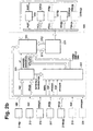
- the figures 2a, 2b and 2c show for the different road vehicles, each in an overview arrangement, the inventive Device for performing the invention Process.
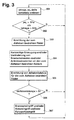
- Figure 3 are with the help of a flow chart to carry out the method according to the invention essential steps shown.
- Figure 4 shows in a schematic representation of how a short-term change of the wheel torque affects the slip of the wheel.
- FIGS. 1a, 1b and 1c represent various road vehicles in which the method according to the invention can be used.
- FIG. 1a A one-piece vehicle 101 is shown in FIG. 1a.
- This vehicle can be both a passenger car as well as a commercial vehicle.
- It should be one-piece vehicle 101 shown in Figure 1a are a vehicle with at least two wheel axles, which is indicated by the partially dashed representation is.
- the wheel axles of vehicle 101 are designated 103ix.
- the index i indicates whether it is a front axle (v) or a rear axle (h).
- By the Index x is given for vehicles with more than two axles, which of the front or rear axles it is. The following assignment applies: The front axle or the rear axle that is closest to the edge of the vehicle, the index x with the smallest value is assigned is. The further the respective wheel axis from the vehicle boundary removed, the greater the value of its Index x.
- the wheels 102ixj are assigned to the wheel axles 103ix.
- the meaning of the indices i and x corresponds to that above . described
- the index j indicates whether the wheel on the right (r) or on the left (1) Vehicle side is located.
- the wheels 102ixj the distinction between single wheels or Twin wheels dispensed with.
- the vehicle 101 further includes a control unit 104, in which the device according to the invention to carry out the method according to the invention is implemented.
- a two-axle vehicle contains a front axle 103v1 with the wheels assigned to it 102v1r or 102v11 and a rear axle 103h1 with it assigned wheels 102h1r and 102h11.
- a three-axis Vehicle normally has a front axle 103v1 with the Wheels 102v1r and 102v11, as well as a first rear axle 103h1 with the wheels 102h1r or 102h1l and a second one Rear axle 103h2 with the wheels 102h2r or 102h21.
- Figure 1b is a vehicle combination consisting of a Tractor 105 and a trailer 106 shown.
- the selected display should not be a limitation, A vehicle combination consisting of a Tractor and a drawbar trailer exists.
- the tractor 105 should have the wheel axles 108iz.
- the wheel axles 108iz the corresponding wheels 107ijz are assigned.
- the meaning of the indices i and j corresponds to that already in context described with Figure 1a.
- the index z indicates that it is wheel axles or wheels of the tractor.
- the tractor 105 has a control unit 109, with a tendency of the tractor 105 to tip over and / or one Tipping tendency of the trailer 106 and / or a tipping tendency of the entire vehicle combination by a longitudinally oriented Vehicle axis is recognized.
- the trailer 106 should two wheel axles 108ixa included.
- the two wheel axles 108ixa the wheels 107ixja are assigned accordingly.
- the meaning of the indices i or x or j already corresponds to that shown in connection with Figure 1a.
- the index a indicates that these are components of the trailer 106 is.
- the number of wheel axles shown in FIG. 1b none for the tractor 105 or for the trailer 106 Show restriction.
- the control unit 109 can instead arranged in the tractor 105 also in the trailer 106 his.
- Figure 1c is one of the vehicle combination shown in Figure 1b corresponding vehicle combination shown.
- the tractor, the trailer, the Wheel axles and the wheels are marked with the same reference numerals.
- the main difference between Figure 1c and Figure 1b is that the vehicle combination according to Figure 1c has two control units.
- the tractor 105 A control device 110 according to the invention is assigned.
- the Trailer 106 is assigned a control unit 111 according to the invention.
- a process is running in both control units Detection of a tendency to tip over.
- the marking chosen in FIGS. 1a, 1b and 1c through the indices a, i, j, x and z is for all sizes or components in which it is used accordingly.
- FIGS. 2a, 2b and 2c Embodiments are discussed that are based on those in the Figures 1a, 1b and 1c shown different vehicles decline.
- the for that shown in Figure 1a Vehicle 101 implemented in the associated control unit 104
- the device according to the invention is described with reference to FIG. 2a.
- the for the vehicle combination shown in Figure 1b implemented according to the invention in the associated control unit 109 Device is described with reference to Figure 2b.
- the tractor 105 has its own control unit 110 and the trailer 106 has its own control unit 111.
- the Cooperation between the two control units 110 and 111 is based on of Figure 2c described.
- the first exemplary embodiment is to be illustrated with the aid of FIG. 2a to be discribed.
- FIG. 1a a one-piece vehicle. It is also assumed that this one-piece vehicle has at least two wheel axles 103ix. These two wheel axles should be the front axle 103v1 with the wheels 102v1r or 102v1l and around Act the rear axle 103h1 with the wheels 102h1r or 102h1l.
- the wheel speed sensors belonging to these wheels 201v1r, 201v1l, 201h1r and 201h11 are shown in FIG. 2a.
- further wheel speed sensors 201ixj are taken into account.
- the sizes nixj are determined that each describe the wheel speed of the corresponding wheel 102ixj.
- the wheel speed sensors 201ixj are independent of the type of regulator 209 definitely present and the quantities generated with them become independent of the Type of the implemented in the device according to the invention Regulator 209 blocks 205 and 209 supplied in any case.
- controller 209 Depending on the type of device in the device according to the invention implemented controller 209 are different Sensors available. Is the regulator 209 around a brake slip controller, which due to the running in it Control intervenes in the wheel brakes and / or acts controller 209 is a traction control system, the due to the regulation running in it in the wheel brakes and / or engages in the engine, so are the wheel speed sensors 201ixj, as already indicated above, to everyone Case available. In this case, however, there is no lateral acceleration sensor 202, no yaw rate sensor 203 and also no steering angle sensor 204 is present.
- controller 209 is a controller, which in its basic function is the driving dynamics of the vehicle descriptive size, for example one of the Lateral acceleration and / or the yaw rate of the vehicle dependent Size, by interventions in the wheel brakes and / or in regulates the motor - such a regulator is off, for example the in the automotive engineering magazine (ATZ) 16, 1994, Issue 11, published on pages 674 to 689 "FDR - the driving dynamics control from Bosch" known -, So are - as shown in Figure 2a - in addition to the wheel speed sensors 201ixj also a lateral acceleration sensor 202, a yaw rate sensor 203 and a steering angle sensor 204 are provided.
- the vehicle descriptive size for example one of the Lateral acceleration and / or the yaw rate of the vehicle dependent Size
- controller 209 or in block 206 the quantities determined using the corresponding sensors are processed. This case is shown in Figure 2a. At this point it should be noted that in this case, if the lateral acceleration sensor and / or the yaw rate sensor and / or the steering angle sensor should fail, which corresponding size also derived from the wheel speeds can be.
- FIG. 2a The representation chosen in FIG. 2a is not intended to be a limitation represent. Depending on the type of implemented Controls are as indicated above, possibly slight modifications required.
- the vehicle 101 has a Lateral acceleration sensor 202, a yaw rate sensor 203 and includes a steering angle sensor 204.
- the use of the lateral acceleration sensor 202 or that of the yaw rate sensor 203 or that of the steering angle sensor 204 is not a limitation should.
- the corresponding sizes can also start from the sizes nixj can be determined.
- the quantity describing the lateral acceleration of the vehicle aq which is determined with the aid of the lateral acceleration sensor 202 which describes the yaw rate of the vehicle Size omega, which is determined using the yaw rate sensor 203 and that describes the steering angle of the vehicle Size delta, which is determined using the steering angle sensor blocks 206 and 209 are fed.
- the sizes nixj become known in a known manner the vehicle speed describing variable vf determined. Starting from block 205, this variable vf becomes the block 209 fed. Furthermore, starting from the Sizes nixj, as well as size vf, sizes in a known manner lambdaixj determines the drive and / or brake slip describe the wheels. These sizes lambdaixj are going out from block 205 to both block 206 and block 209 fed.
- the wheels of the vehicle are determined in block 206, which threatens to take off due to the driving condition are.
- the wheels of the vehicle determined to detect a tendency of the vehicle to tip over around one oriented in the longitudinal direction of the vehicle Vehicle axle are suitable.
- the determination of these wheels is at least dependent from one of the determined, the lateral dynamics of the vehicle representative quantities delta or aq or omega, which are fed to block 206.
- This is done in block 206 from the size delta and / or describing the steering angle from the one describing the lateral acceleration of the vehicle Size aq and / or from the one describing the yaw rate of the vehicle Size omega determines a size starting from which is recognizable whether and what kind of a curve, i.e. left or Right turn, the vehicle drives through.
- the one on the steering angle or the lateral acceleration of the vehicle based curve detection shows.
- curve detection based on the yaw rate of the vehicle conceivable.
- signals SMixj or SM are generated, starting from those on at least one of those at risk of taking off Wheels briefly braking torques and / or driving torques generated and / or changed. Because of the take off endangered wheels sensitive to changes in wheel dynamics can react, for example, by evaluating the Slip values of the wheels threatened by lifting were determined whether the vehicle has a tendency to tip over or Not.
- the sizes SMixj and SM generated in block 206 become the Block 209 fed.
- Starting from the Size SM becomes a means assigned to motor 211, with which the engine torque delivered by the engine can be influenced.
- the sizes SMixj and SM are in block 206 generated so that on the respective wheels threatened to take off briefly a braking torque and / or a driving torque is generated and / or changed. This is done by appropriate Activation of the respective wheel threatened to lift off associated actuator 213ixj built a small braking torque and / or there is a slight change an already generated braking torque. This is done by appropriate Control of the assigned to the engine of the vehicle By means of and the actuators assigned to the wheels 213ixj generates and / or produces a low driving torque a slight change to an already created one Drive torque.
- the slip values of lambdaixja of the wheels threatened with take off are fed from block 206 to a block 207.
- the two blocks 206 and 207 which are essential to the invention are combined into a block 208.
- a size KT is generated in block 207 which starting from block 207 is supplied to block 209.
- KT is communicated to the controller or vehicle controller 209, whether the vehicle has a tendency to tip over or Not.
- the controller implemented in control unit 104 is at 209 or vehicle controller.
- Regulator 209 acts it is, for example, a controller with its basic function a description of the driving dynamics of the vehicle Size, for example one of the lateral acceleration and / or the yaw rate of the vehicle dependent size Interventions in the wheel brakes and / or in the engine regulates.
- Such a controller is, for example, from the automotive industry Zeitschrift (ATZ) 16, 1994, Issue 11, on the Pages 674 to 689 appeared publication "FDR - die Vehicle dynamics control from Bosch ".
- the in block 209 in its basic function is based on known regulations Way on the quantities nixj supplied to block 209, delta, aq, omega, vf, lambdaixj, a size mot2, for example describes the engine speed of engine 211 and which, starting from the motor 211, is fed to the block 209 and variables ST2, which, starting from a block 210, which is the control logic for those contained in the vehicle Actuators, the block 209 are supplied.
- controller 209 Brake slip control that engages the wheel brakes and / or a traction control system in the wheel brakes and / or engages in the engine.
- the controller fulfills essentially two tasks. Firstly, he sets the sizes SMixj or SM in the corresponding signal ST1 to that of the control logic 210 are fed, and starting from those the wheels threatened by lifting briefly braking torque and / or drive torques are generated and / or changed. On the other hand, it leads based on the quantities supplied to it KT does the actual tip-over prevention. This overturn prevention can virtually control the control of the basic function his.
- the variables 209 can be communicated to the controller 209 be that a tipping tendency of the vehicle by one in Vehicle axis oriented in the longitudinal direction of the vehicle, the controller 209 can also be told how strong is this tendency to tip, how or over which wheels the vehicle threatens to tip over.
- the controller 209 generates variables ST1, which are supplied to the control logic 210 with which the actuators assigned to the vehicle are controlled.
- the control logic 210 is informed with the variables ST1 which actuators are to be controlled and how.
- the variables ST1 are generated in the controller 209, for example, as follows. If there is no tendency for the vehicle to tip over and the wheel torques are not influenced briefly according to the invention, the variables ST1 are generated in accordance with the control implemented for the basic function. For example, if it is a control described in the publication "FDR - the driving dynamics control from Bosch", the sizes ST1 contain information about which or which wheels are to be braked and to what extent the engine torque output by the engine should be influenced.
- variables ST1 are conceivable.
- the variables ST1 * which were determined in accordance with the control concept implemented for the basic function, can be modified in such a way that the vehicle does not tip over about a vehicle axis oriented in the longitudinal direction of the vehicle, or that the short-term influences of the wheel moments are carried out according to the invention
- the variables ST1 * determined in accordance with the control concept implemented for the basic function can be replaced by variables which are generated in order to prevent the vehicle from tipping over or to carry out the brief influences of the wheel moments according to the invention.
- the control logic those from controller 209 generated variables ST1 in drive signals for the motor 211 as well as in control signals for the actuators of the vehicle implemented.
- the actuators are, for example around suspension actuators 212ixj, with which the behavior of the Chassis can be influenced, as well as actuators 213ixj a braking force can be generated on the corresponding wheels is.
- the control logic generates the control for the motor 211 a signal motl with which, for example, the throttle valve position of the engine can be influenced.
- To control the Suspension actuators 212ixj generate the control logic 210 signals Fsixj, which are used by the chassis actuators 212ixj realized damping or stiffness can be influenced is.
- the control logic 210 Signals Aixj, with which the from the actuators 213ixj to the corresponding wheels generated braking forces can be influenced are.
- the control logic 210 generates variables ST2 that the controller 209 are supplied, and the information about the Control of the individual actuators included.
- the tractor is as shown in Figure 2a 105 with 214ijz wheel speed sensors, a lateral acceleration sensor 215 and a yaw rate sensor 216 and one Steering angle sensor 217 equipped.
- the trailer 106 should at least equipped with wheel speed sensors 218hxja his.
- the trailer can be equipped with a lateral acceleration sensor 219 and a yaw rate sensor 220 his. Normally, i.e. for a steady operating state, would be the lateral acceleration sensor for the trailer 106 219 and the yaw rate sensor 220 are not required, since the lateral acceleration acting on the trailer 106 or the yaw rate occurring on the trailer 106 in each case the Lateral acceleration or yaw rate of tractor 105 equivalent.
- both Lateral acceleration as well as the yaw rate of the trailer 106 determined in a known manner from the wheel speeds of the trailer become. For this reason, both the Lateral acceleration sensor 219 as well as the yaw rate sensor 220 shown in dashed lines.
- Block 221 corresponds to that in FIG. 2a block 205 shown.
- Block 222 corresponds in its Function of those combined to block 208 in FIG. 2a Blocks 206 and 207.
- Block 223 corresponds in its Function of block 209 shown in Figure 2a.
- the block 224 corresponds in its function to that shown in FIG. 2a Block 210.
- the determined for the tractor 105 Sizes nijz, aqz, omegaz and delta are as in context described with Figure 2a, in a corresponding manner Blocks 221, 222 and 223 supplied. Based on the representation in FIG. 2a, the sensors are supplementary to consider the sensors for the trailer 106.
- aqa and omegaa are in the Control unit 109 in a manner corresponding to that for the tractor 105 generated sizes nijz, aqz and omegaz processed. This means that the sizes nhxja both the block 221 and block 223 are fed. If available, the sizes aqa or omegaa the blocks 222 or 223 fed.
- block 221 corresponding to block 205, starting from the sizes nijz or nhxja the speed of the Vehicle combination describing size vf determined. This is fed to block 223. Also in block 221 in a manner corresponding to the sizes in block 205 lambdaijz or lambdahxja determined both the block 222 and the block 223 are fed. In block 222 is determined in accordance with the procedure in block 208, whether for the vehicle combination and / or for the tractor 105 and / or there is a tendency for the trailer 106 to tip.
- both for the wheels Tractor 105 as well as for the wheels of the trailer 106 the wheels threatened by lifting are determined and corresponding SMijza, SMhxjaa and SMz signals generated and the block 223 fed. Furthermore, in block 222 for the take off endangered wheels the changes in the wheel behavior of each Rades descriptive sizes determined. The result The detection of the tendency to tip over is started from block 222 the block 223 communicated by the sizes KTz and KTa.
- the Size KTz contains the information for the tractor 105, the size KTa contains the information for the trailer.
- Block 209 According to the procedure as it relates to Block 209 has been described in block 223 ST1 'determined, which are supplied to the control logic 224.
- the control signal motl determined.
- the actuators 226ijz with which braking forces can be generated, the control signals Aijz are determined.
- the control signals Fsijz are determined.
- the controller 223 starting from the motor 225, a variable mot2, based on the chassis actuators 227ijz sizes Frijz and based on the suspension actuators 229hxja sizes Frhxja fed.
- FIG. 2c the vehicle combination shown in Figure 1c underlying.
- the tractor 105 with a control unit 110 and the trailer 106 can be equipped with a control unit 111.
- the function of components or the meaning of quantities used in Figure 2c are and which are already shown in Figure 2b, identical are.
- the control units 110 and 111 the Supply of the input variables or the output of the output variables 2a and 2b.
- the control unit 110 essentially corresponds to that shown in FIG. 2a Control device 104.
- the control unit 104 in the controller 209 must do so be modified to determine additional sizes SG1 and can output or record additional sizes SG2 and can process.
- the control unit 111 is also from the Control device 104 can be derived in FIG. 2a.
- the controller must do this 209 to be modified to include additional sizes SG2 can determine and output, as well as additional sizes SG1 can receive and process. Because the trailer as actuators only via brakes 228hxja or chassis actuators 229hxja, the one shown in Figure 2a must also Regulator 209 or the control logic 210 in this regard be modified.
- the vehicle combination has two separate control units 110 or 111, is used to coordinate the two control units the exchange of data or sizes SG1 or SG2 required, to coordinate interventions by the two control units.
- the sizes SG1 and SG2 can be exchanged which actuators are actuated.
- the two control units 110 and 111 work autonomously. In this case it is between the two control units do not exchange data or Sizes SG1 and SG2 required.
- the method according to the invention begins with one step 301, in which the sizes omega, aq, delta and lambdaixj be read.
- the sizes omega, aq and delta are either with the help of sensors or from the wheel speeds been derived.
- a step 302 is carried out.
- step 302 it is determined whether there is a driving condition in which there is a tendency to tip over of the vehicle oriented around a longitudinal direction of the vehicle Vehicle axis can occur. This is done in step 302 determines whether the amount of lateral acceleration of the Vehicle descriptive size aq larger than a first Threshold Sla is and / or whether the amount of the yaw rate of the vehicle descriptive size omega larger than one second threshold Slb. It would also be conceivable For example, for a wheel axle, the difference in wheel speeds of the left and right wheel, and this difference with an appropriate threshold to compare.
- Step 302 The alternative linking of the two subqueries in Step 302 has the following reasons: First, the case can present that block 206 has either the lateral acceleration descriptive quantity aq or the descriptive variable describing the yaw rate Size omega can be fed. In this case can inevitably only one of the two subqueries be carried out. On the other hand, there may be the case that both quantities are supplied to block 206. In this case can either execute one of the two subqueries or can, to make the statement more certain, both subqueries are executed simultaneously. is fulfilled at least one of the two partial queries in step 302, so after step 302 becomes a step 303 executed. On the other hand, in step 302, neither is Subqueries are fulfilled, then the step 302, step 301 is carried out again.
- step 303 the data from Lifting the vehicle's endangered wheels is determined, i.e. it the wheels of the vehicle are determined for recognition a tendency of the vehicle to tip over are suitable.
- step 304 is performed.
- this step 304 at least one of the briefly braking torques threatened by lifting and / or driving torques generated and / or changed.
- the purpose is to use the sizes SMixj generated by block 206 and SM in controller 209 and in control logic 210 in corresponding Control signals implemented.
- Interventions can be carried out on all wheels of the vehicle briefly braking torques and / or driving torques generated and / or changed.
- step 305 is performed.
- this step 305 is for those threatened to take off Wheels each the change deltalambdaixja of that Wheel behavior quantitatively descriptive size determined.
- the the size describing the change deltalambdaixja is during the length of time in which the braking torques and / or the driving torques generated briefly on the respective wheel and / or be changed and / or after the braking torques and / or the drive torques on the respective wheel for a short time generated and / or changed. At this Place is already on the figure 4 to be described directed.
- Step 305 becomes a step 306 executed.
- deltalambdaixja determines whether the vehicle has a tendency to tip over about a vehicle axis oriented in the longitudinal direction of the vehicle is present. There is a tendency to tip over if the amount of size deltalambdaixja larger than a corresponding one Threshold S2 is. In this case, then to step 306, step 307 is performed.
- step 301 is executed again.
- step 307 due to the fact that a tipping tendency of the vehicle by one in the longitudinal direction of the vehicle oriented vehicle axis, brake interventions and / or engine interventions and / or interventions on chassis actuators carried out with which a stabilization of the Vehicle is reached.
- the brake interventions i.e. the interventions on the actuators 213ixj, and the engine interventions serve primarily reducing vehicle speed.
- brake interventions on individual Wheels stabilizing yaw moments in a known manner be generated.
- the roll motion can be carried out on the chassis actuators 212ixj of the vehicle partially compensated and the location of the Focus can be influenced.
- step 301 becomes again executed.
- FIG. 4 shows the relationship for a wheel threatened with lifting between creating and / or changing a moment Mixja acting on the wheel and the resulting one Influence on the quantitative description of the wheel behavior
- Size lambdaixja shown. Is it at this moment by a braking moment, then the size represents lambdaixja represents the brake slip. If it is a drive torque, then the size lambdaixja provides the drive slip As can be seen in FIG. 4, generation takes place and / or changing the moment acting on the wheel to an increase in the corresponding slip size.
- the resulting Change during the period defined by t1 and t2 is, based on the values lambdall to lambdal4, that exist at times t11 to t14 are determined. For example, by considering several these values the gradient of the wheel behavior quantitative descriptive size lambdaixja can be determined.
- the resulting change from the values lambdal and lambda2 are determined after the corresponding moments were created and / or changed. For this purpose store the value of lambdal in a storage medium.
- the method according to the invention or the inventive Device relates to detection a tendency of a vehicle to tip over in the longitudinal direction of the vehicle oriented vehicle axis. For this it is determined whether one of the wheels of the vehicle is lifting. Taking off A wheel on the vehicle is characterized in that the normal force transmitted by the wheel goes to zero and none or only small peripheral forces, i.e. Lateral or longitudinal forces, transmitted through the tire to the road. In such a state, the slip conditions are most important Wheel particularly sensitive to changes the wheel dynamics. These relationships can be advantageous use for the detection of the lifting of a wheel.
- This slip change can be used for detection a lifting wheel and thus to detect a tendency to tip over of a vehicle by one in the longitudinal direction of the vehicle use oriented vehicle axis.
Claims (14)
- Procédé permettant de détecter une tendance au basculement d'un véhicule autour d'un axe de véhicule orienté dans le sens longitudinal du véhicule, selon lequel une valeur décrivant la vitesse de rotation de la roue est indiquée pour au moins une roue, au moins une valeur représentant la dynamique verticale du véhicule est indiquée, au cours duquel des couples de freinage et/ou des couples d'entraínement sont produits et/ou modifiés à court terme sur au moins une roue, au moins en fonction de l'une des valeurs représentant la dynamique verticale du véhicule, dans lequel, pendant que les couples de freinage et/ou les couples d'entraínement sont produits et/ou modifiés à court terme sur au moins une roue et/ou après que les couples de freinage et/ou les couples d'entraínement aient été produits et/ou modifiés à court terme sur au moins une roue, une valeur décrivant de manière quantitative le comportement de la roue est déterminée au moins en fonction de la valeur décrivant la vitesse de rotation de cette roue pour au moins cette roue, et au moins en fonction de la valeur déterminée pour au moins cette roue, valeur qui décrit de manière quantitative le comportement de cette roue, il est déterminé s'il existe, pour le véhicule, une tendance au basculement autour d'un axe de véhicule orienté dans le sens longitudinal du véhicule.
- Procédé selon la revendication 1,
caractérisé en ce que
le procédé permettant de détecter une tendance au basculement d'un véhicule autour d'un axe de véhicule orienté dans le sens longitudinal du véhicule est utilisé dans le cadre d'un procédé de stabilisation du véhicule, en particulier dans le cadre d'un procédé permettant d'éviter le basculement du véhicule, et s'il y a une tendance au basculement d'un véhicule autour d'un axe de véhicule orienté dans le sens longitudinal du véhicule, au moins des prises de freins sont assurées sur au moins une roue et/ou des prises de moteur et/ou des prises sur les éléments du dispositif de roulement sont assurées pour stabiliser le procédé, en particulier pour éviter le basculement du véhicule. - Procédé selon la revendication 2,
caractérisé en ce qu'
une prise de freins est assurée au moins sur la roue avant à l'extérieur de la courbe pour stabiliser le véhicule, de telle sorte qu'un couple de freinage est produit et/ou augmenté sur cette roue. - Procédé selon la revendication 1,
caractérisé en ce que
l'ordre de grandeur de l'une des valeurs représentant la dynamique verticale du véhicule est comparée à une valeur de seuil, et on détecte s'il y a une tendance au basculement du véhicule autour d'un axe de véhicule orienté dans le sens longitudinal du véhicule si l'ordre de grandeur de l'une des valeurs représentant la dynamique verticale du véhicule est supérieur à la valeur de seuil. - Procédé selon la revendication 4,
caractérisé en ce qu'
une des valeurs décrivant l'accélération verticale et/ou une des valeurs décrivant le taux de lacet du véhicule est enregistrée comme une des valeurs représentant la dynamique verticale du véhicule à l'aide d'un moyen de mesure adapté, et/ou est déterminée au moins en fonction des valeurs décrivant la vitesse de rotation des roues. - Procédé selon la revendication 1,
caractérisé en ce qu'
il est défini quelles roues du véhicule sont adaptées pour détecter une tendance au basculement du véhicule autour d'un axe de véhicule orienté dans le sens longitudinal du véhicule, au moins en fonction de l'une des valeurs déterminées représentant la dynamique verticale du véhicule, et la détection de la tendance au basculement du véhicule autour d'un axe de véhicule orienté dans le sens longitudinal du véhicule s'effectue grâce au moins à l'une de ces roues, dans la mesure où des couples de freinage et/ou des couples d'entraínement sont produits et/ou modifiés à court terme sur au moins une des roues. - Procédé selon la revendication 6,
caractérisé en ce qu'
fonction d'une valeur déterminée à partir de l'une des valeurs décrivant l'angle de déviation et/ou de l'une des valeurs décrivant l'accélération verticale du véhicule et/ou de l'une des valeurs décrivant le taux de lacet du véhicule, on détermine si le véhicule traverse une courbe et pour détecter une tendance au basculement du véhicule autour d'un axe de véhicule orienté dans le sens longitudinal du véhicule, au moins une des roues du véhicule est sélectionnée, à savoir celle qui se trouve sur le côté intérieur de la courbe. - Procédé selon la revendication 6,
caractérisé en ce que
lorsque le système détermine quelles roues du véhicule sont adaptées pour détecter une tendance au basculement du véhicule et/ou lors de la production et/ou de la modification à court terme des couples de freinage et/ou des couples d'entraínement sur au moins une roue, le concept d'entrainement du véhicule est, en plus, pris en considération. - Procédé selon la revendication 1,
caractérisé en ce que
pour la production et/ou la modification à court terme du couple de freinage, l'élément affecté à chaque roue, avec lequel les couples de freinage peuvent être produits, est commandé de telle sorte qu'un couple de freinage faible est créé et/ou qu'une modification négligeable d'un couple de freinage déjà produit est assurée, et/ou pour la production et/ou la modification à court terme du couple d'entraínement, un moyen affecté au moteur du véhicule et grâce auquel le couple moteur délivré par le moteur peut être influencé ainsi que les éléments affectés aux roues grâce auxquels des couples de freinage peuvent être produits sur chaque roue, sont commandés de telle sorte qu'un couple d'entraínement faible est créé et/ou qu'une modification négligeable d'un couple d'entraínement déjà produit est assurée. - Procédé selon la revendication 1,
caractérisé en ce qu'
une valeur décrivant le glissement de chaque roue est déterminée, pour au moins une roue, comme la valeur décrivant de manière quantitative le comportement de la roue, et/ou une valeur décrivant la vitesse de rotation de la roue correspondante et/ou la modification à court terme de la valeur décrivant la vitesse de rotation de la roue correspondante peut être utilisée, pour au moins une roue, comme la valeur décrivant de manière quantitative le comportement de la roue, en particulier, la valeur décrivant le glissement de chaque roue est déterminée au moins en fonction de la valeur correspondante décrivant la vitesse de rotation de la roue et d'une valeur décrivant la vitesse du véhicule, la valeur décrivant la vitesse du véhicule étant déterminée au moins en fonction des valeurs déterminées pour les roues et qui décrivent les vitesses de rotation des roues. - Procédé selon la revendication 1,
caractérisé en ce que
pour détecter une tendance au basculement du véhicule autour d'un axe de véhicule orienté dans le sens longitudinal du véhicule, pendant la durée au cours de laquelle les couples de freinage et/ou les couples d'entraínement sont produits et/ou modifiés à court terme sur au moins une roue et/ou après que les couples de freinage et/ou les couples d'entraínement aient été produits et/ou modifiés à court terme sur au moins une roue, on détermine la modification apportée à la valeur décrivant de manière quantitative le comportement de la roue, et il y a une tendance au basculement du véhicule autour d'un axe de véhicule orienté dans le sens longitudinal du véhicule si l'ordre de grandeur de la modification apportée à la valeur décrivant de manière quantitative le comportement de la roue est supérieur à une valeur de seuil correspondante. - Procédé selon la revendication 1,
caractérisé en ce que
les couples de freinage et/ou les couples d'entraínement sont produits et/ou modifiés à court terme simultanément sur toutes les roues du véhicule au moins en fonction de l'une des valeurs représentant la dynamique verticale du véhicule. - Dispositif permettant de détecter une tendance au basculement d'un véhicule autour d'un axe de véhicule orienté dans le sens longitudinal du véhicule, comprenant .
un premier moyen grâce auquel une valeur décrivant la vitesse de rotation de la roue est déterminée pour au moins une roue, et
un deuxième moyen grâce auquel au moins une valeur représentant la dynamique verticale du véhicule est déterminée,
caractérisé en ce qu'
il comprend encore un troisième moyen grâce auquel des signaux sont produits au moins en fonction d'une des valeurs représentant la dynamique verticale du véhicule, grâce auquel, au moins pour une roue, l'élément affecté à la roue correspondante avec lequel des couples de freinage peuvent être produits est commandé de telle sorte que des couples de freinage sont produits et/ou modifiés à court terme sur cette roue, et/ou grâce auquel un moyen affecté au moteur et influençant le couple moteur délivré par le moteur, et les éléments affectés aux roues sont commandés de telle sorte que des couples d'entraínement sont produits et/ou modifiés à court terme sur au moins une roue,
il comprend un quatrième moyen grâce auquel, pendant que les couples de freinage et/ou les couples d'entraínement sont produits et/ou modifiés à court terme sur au moins une roue et/ou après que les couples de freinage et/ou les couples d'entraínement aient été produits et/ou modifiés à court terme sur au moins une roue, une valeur décrivant de manière quantitative le comportement de la roue est déterminée au moins en fonction de la valeur déterminée à l'aide des premiers moyens pour la roue correspondante, pour au moins cette roue, et
il comprend un cinquième moyen qui détermine, au moins en fonction de la valeur déterminée à l'aide des quatrièmes moyens pour la roue correspondante, s'il y a pour le véhicule une tendance au basculement autour d'un axe de véhicule orienté dans le sens longitudinal du véhicule. - Dispositif selon la revendication 13,
caractérisé en ce que
le dispositif permettant de détecter une tendance au basculement d'un véhicule autour d'un axe de véhicule orienté dans le sens longitudinal du véhicule est utilisé dans un dispositif de stabilisation du véhicule, en particulier dans un dispositif permettant d'éviter le basculement du véhicule, et s'il y a une tendance au basculement du véhicule autour d'un axe de véhicule orienté dans le sens longitudinal du véhicule, on active, pour stabiliser le véhicule, en particulier pour éviter le basculement du véhicule, au moins les éléments affectés à cette roue sur au moins une roue afin de produire une force de freinage et/ou un moyen permettant d'influencer le couple moteur et/ou les éléments du dispositifs de roulement et, en particulier, une prise de freins est assurée au moins sur la roue avant à l'extérieur de la courbe de telle sorte qu'un couple de freinage est produit et/ou est augmenté sur cette roue.
Applications Claiming Priority (3)
| Application Number | Priority Date | Filing Date | Title |
|---|---|---|---|
| DE19751925A DE19751925A1 (de) | 1997-11-22 | 1997-11-22 | Verfahren und Vorrichtung zur Erkennung einer Kipptendenz eines Fahrzeuges |
| DE19751925 | 1997-11-22 | ||
| PCT/DE1998/002141 WO1999026812A1 (fr) | 1997-11-22 | 1998-07-29 | Procede et dispositif pour detecter la tendance au basculement d'un vehicule |
Publications (2)
| Publication Number | Publication Date |
|---|---|
| EP0954461A1 EP0954461A1 (fr) | 1999-11-10 |
| EP0954461B1 true EP0954461B1 (fr) | 2003-10-01 |
Family
ID=7849602
Family Applications (1)
| Application Number | Title | Priority Date | Filing Date |
|---|---|---|---|
| EP98947361A Revoked EP0954461B1 (fr) | 1997-11-22 | 1998-07-29 | Procede et dispositif pour detecter la tendance au basculement d'un vehicule |
Country Status (5)
| Country | Link |
|---|---|
| US (1) | US6272420B1 (fr) |
| EP (1) | EP0954461B1 (fr) |
| JP (1) | JP2001511740A (fr) |
| DE (2) | DE19751925A1 (fr) |
| WO (1) | WO1999026812A1 (fr) |
Families Citing this family (46)
| Publication number | Priority date | Publication date | Assignee | Title |
|---|---|---|---|---|
| US7090040B2 (en) * | 1993-02-24 | 2006-08-15 | Deka Products Limited Partnership | Motion control of a transporter |
| DE19751891A1 (de) * | 1997-11-22 | 1999-05-27 | Bosch Gmbh Robert | Verfahren und Vorrichtung zur Stabilisierung eines Fahrzeuges bei Kipptendenz |
| WO2000053447A1 (fr) * | 1999-03-08 | 2000-09-14 | Continental Teves Ag & Co. Ohg | Procede d'antipatinage avec acceleration transversale theorique, et circuit de reglage destine a la mise en oeuvre de ce procede |
| WO2001002227A1 (fr) * | 1999-06-30 | 2001-01-11 | Robert Bosch Gmbh | Procede et dispositif pour stabiliser un vehicule |
| DE10039108B4 (de) * | 1999-08-13 | 2012-03-22 | Continental Teves Ag & Co. Ohg | Verfahren und Vorrichtung zum Bestimmen von Fahrzeugzustandsgrößen |
| DE10023521A1 (de) * | 1999-11-02 | 2001-05-03 | Continental Teves Ag & Co Ohg | Verfahren zur Erkennung eines freidrehenden Rades in einem Kraftfahrzeug |
| DE19958221A1 (de) | 1999-12-02 | 2001-06-07 | Wabco Gmbh & Co Ohg | Verfahren zur Verhinderung des Umkippens eines Fahrzeugs |
| US6332104B1 (en) | 1999-12-21 | 2001-12-18 | Ford Global Technologies, Inc. | Roll over detection for an automotive vehicle |
| US6834218B2 (en) | 2001-11-05 | 2004-12-21 | Ford Global Technologies, Llc | Roll over stability control for an automotive vehicle |
| US6263261B1 (en) | 1999-12-21 | 2001-07-17 | Ford Global Technologies, Inc. | Roll over stability control for an automotive vehicle |
| US6324446B1 (en) | 1999-12-21 | 2001-11-27 | Ford Global Technologies, Inc. | Roll over stability control for an automotive vehicle |
| DE10000550B4 (de) * | 2000-01-08 | 2005-09-15 | Bayerische Motoren Werke Ag | Vorrichtung zur Detektion von Überschlägen bei einem Fahrzeug |
| DE10017045A1 (de) * | 2000-04-05 | 2001-10-11 | Wabco Gmbh & Co Ohg | Verfahren zur Vermeidung des Umkippens eines Fahrzeuges um seine Längsachse |
| DE10046036A1 (de) * | 2000-09-18 | 2002-03-28 | Knorr Bremse Systeme | Verfahren zum Abschätzen der Umkippgefahr eines Fahrzeugs |
| US6397127B1 (en) | 2000-09-25 | 2002-05-28 | Ford Global Technologies, Inc. | Steering actuated wheel lift identification for an automotive vehicle |
| US7132937B2 (en) * | 2000-09-25 | 2006-11-07 | Ford Global Technologies, Llc | Wheel lift identification for an automotive vehicle using passive and active detection |
| US6356188B1 (en) * | 2000-09-25 | 2002-03-12 | Ford Global Technologies, Inc. | Wheel lift identification for an automotive vehicle |
| JP3546830B2 (ja) * | 2000-10-05 | 2004-07-28 | トヨタ自動車株式会社 | 車輌のロール挙動制御装置 |
| US6799092B2 (en) | 2001-02-21 | 2004-09-28 | Ford Global Technologies, Llc | Rollover stability control for an automotive vehicle using rear wheel steering and brake control |
| DE10133409A1 (de) * | 2001-07-13 | 2003-01-30 | Lucas Automotive Gmbh | Fahrzeugbremssystem |
| US6654674B2 (en) | 2001-11-21 | 2003-11-25 | Ford Global Technologies, Llc | Enhanced system for yaw stability control system to include roll stability control function |
| DE10208619A1 (de) | 2002-02-27 | 2003-09-04 | Bosch Gmbh Robert | Verfahren und Vorrichtung zur Erkennung abgehobener Fahrzeugräder |
| US7302331B2 (en) * | 2002-08-01 | 2007-11-27 | Ford Global Technologies, Inc. | Wheel lift identification for an automotive vehicle |
| DE10256539B4 (de) * | 2002-12-04 | 2006-02-16 | Jungheinrich Ag | Vierradflurförderzeug mit Pendelachse |
| DE10301096A1 (de) * | 2003-01-14 | 2004-08-05 | Wabco Gmbh & Co. Ohg | Verfahren zur Fahrdynamikregelung für einen Fahrzeugzug |
| US9162656B2 (en) | 2003-02-26 | 2015-10-20 | Ford Global Technologies, Llc | Active driven wheel lift identification for an automotive vehicle |
| US7653471B2 (en) * | 2003-02-26 | 2010-01-26 | Ford Global Technologies, Llc | Active driven wheel lift identification for an automotive vehicle |
| DE10357254B4 (de) * | 2003-12-08 | 2014-11-13 | Knorr-Bremse Systeme für Nutzfahrzeuge GmbH | Verfahren zum Kompensieren des durch eine Änderung des Abrollverhaltens eines Laufrades eines Fahrzeugs hervorgerufenen Giermoments |
| WO2005082680A1 (fr) * | 2004-03-01 | 2005-09-09 | Continental Teves Ag & Co.Ohg | Dispositif pour determiner une tendance au basculement |
| US7668645B2 (en) | 2004-10-15 | 2010-02-23 | Ford Global Technologies | System and method for dynamically determining vehicle loading and vertical loading distance for use in a vehicle dynamic control system |
| US7715965B2 (en) | 2004-10-15 | 2010-05-11 | Ford Global Technologies | System and method for qualitatively determining vehicle loading conditions |
| US7660654B2 (en) | 2004-12-13 | 2010-02-09 | Ford Global Technologies, Llc | System for dynamically determining vehicle rear/trunk loading for use in a vehicle control system |
| US7590481B2 (en) | 2005-09-19 | 2009-09-15 | Ford Global Technologies, Llc | Integrated vehicle control system using dynamically determined vehicle conditions |
| US7600826B2 (en) | 2005-11-09 | 2009-10-13 | Ford Global Technologies, Llc | System for dynamically determining axle loadings of a moving vehicle using integrated sensing system and its application in vehicle dynamics controls |
| US8121758B2 (en) | 2005-11-09 | 2012-02-21 | Ford Global Technologies | System for determining torque and tire forces using integrated sensing system |
| DE102007012164A1 (de) * | 2007-03-12 | 2008-09-18 | Continental Teves Ag & Co. Ohg | Quad |
| GB2454223B (en) * | 2007-11-01 | 2011-09-21 | Haldex Brake Products Ltd | Vehicle stability control method |
| WO2012030643A2 (fr) | 2010-09-02 | 2012-03-08 | Kelsey-Hayes Company | Stratégie de contrôle de la vitesse |
| DE102011111862A1 (de) | 2011-08-31 | 2013-02-28 | Wabco Gmbh | Verfahren zur Warnung des Fahrers eines Fahrzeuges vor einem drohenden Umkippen und Steuerungseinrichtung dafür |
| DE102011084842B4 (de) | 2011-10-20 | 2017-12-14 | Robert Bosch Gmbh | Verfahren zur Erzeugung einer Freiflughinweisinformation für ein Fahrzeug und Verfahren zur Erkennung eines Freiflugzustandes eines Fahrzeugs |
| DE102012101274A1 (de) * | 2012-02-17 | 2013-08-22 | Continental Automotive Gmbh | Verfahren zur Steuerung eines Kraftfahrzeugs während und unmittelbar nach einer Flugphase |
| DE102013012992A1 (de) * | 2013-08-02 | 2015-02-05 | Wabco Gmbh | Verfahren und Fahrdynamikregelungseinrichtung zur Ermittlung kritischer Querbeschleunigungswerte eines Kraftfahrzeugs |
| EP3354543B1 (fr) * | 2015-10-23 | 2021-03-10 | Komatsu Ltd. | Dispositif de détermination d'indication de renversement de véhicule polyvalent, et véhicule polyvalent |
| WO2018124971A1 (fr) | 2016-12-30 | 2018-07-05 | Elaphe Propulsion Technologies Ltd. | Agencement permettant de déterminer un couple maximal admissible |
| GB2565851B (en) | 2017-08-25 | 2022-05-04 | Haldex Brake Prod Ab | Braking system |
| DE102018119574A1 (de) * | 2018-08-13 | 2020-02-13 | Knorr-Bremse Systeme für Nutzfahrzeuge GmbH | Umkippverhinderungsvorrichtung und Verfahren zum Verhindern eines Umkippens eines Fahrzeugs und Fahrzeug |
Family Cites Families (16)
| Publication number | Priority date | Publication date | Assignee | Title |
|---|---|---|---|---|
| FR1560462A (fr) | 1968-01-16 | 1969-03-21 | ||
| US4023864A (en) | 1973-09-20 | 1977-05-17 | Lang Davis Industries, Inc. | Automatic stability control system with strain gauge sensors |
| FR2425342A1 (fr) | 1978-05-12 | 1979-12-07 | Saint Marcel Ste Metallurg | Ralentisseur anti-renversement pour vehicules routiers lourds |
| JPS5695768A (en) | 1979-12-27 | 1981-08-03 | Toyo Umpanki Co Ltd | Device for preventing turnover of special vehicle |
| DE3222114A1 (de) | 1982-06-11 | 1983-12-15 | Friedrich W. 5340 Bad Honnef Odenberg | Liftsystem, als kurvengaengiger treppenschraegaufzug |
| JPH01101238A (ja) | 1987-10-14 | 1989-04-19 | Matsushita Electric Ind Co Ltd | 速度制御装置 |
| DE3805589A1 (de) | 1988-02-23 | 1989-08-31 | Lucas Ind Plc | Verfahren und vorrichtung zum steuern einer bremsanlage fuer schwerfahrzeuge |
| DE3933653B4 (de) | 1989-10-09 | 2004-05-27 | Robert Bosch Gmbh | Radschlupfregelsystem |
| GB2257403A (en) | 1991-07-06 | 1993-01-13 | Gloster Saro Ltd | Road vehicle stability indicating system. |
| DE4228893B4 (de) * | 1992-08-29 | 2004-04-08 | Robert Bosch Gmbh | System zur Beeinflussung der Fahrdynamik eines Kraftfahrzeugs |
| DE4342732A1 (de) | 1993-12-15 | 1995-06-22 | Anton Ellinghaus Maschinenfabr | Tankfahrzeug mit Kippsensor |
| DE4416991A1 (de) | 1994-05-13 | 1995-11-16 | Pietzsch Ag | Verfahren und Einrichtung zum Warnen der Fahrer von Lastkraftwagen vor Kippgefahr bei Kurvenfahrten |
| US5446658A (en) | 1994-06-22 | 1995-08-29 | General Motors Corporation | Method and apparatus for estimating incline and bank angles of a road surface |
| US5471386A (en) * | 1994-10-03 | 1995-11-28 | Ford Motor Company | Vehicle traction controller with torque and slip control |
| DE19602879C1 (de) | 1996-01-29 | 1997-08-07 | Knorr Bremse Systeme | Verfahren zum Erfassen der Gefahr des Umkippens eines Fahrzeuges |
| DE19655388B4 (de) | 1996-08-16 | 2008-08-14 | Daimler Ag | Fahrdynamikregelungssystem und Verfahren |
-
1997
- 1997-11-22 DE DE19751925A patent/DE19751925A1/de not_active Ceased
-
1998
- 1998-07-29 DE DE59809803T patent/DE59809803D1/de not_active Revoked
- 1998-07-29 WO PCT/DE1998/002141 patent/WO1999026812A1/fr not_active Application Discontinuation
- 1998-07-29 US US09/355,133 patent/US6272420B1/en not_active Expired - Fee Related
- 1998-07-29 JP JP52728999A patent/JP2001511740A/ja not_active Ceased
- 1998-07-29 EP EP98947361A patent/EP0954461B1/fr not_active Revoked
Also Published As
| Publication number | Publication date |
|---|---|
| DE59809803D1 (de) | 2003-11-06 |
| DE19751925A1 (de) | 1999-05-27 |
| EP0954461A1 (fr) | 1999-11-10 |
| WO1999026812A1 (fr) | 1999-06-03 |
| JP2001511740A (ja) | 2001-08-14 |
| US6272420B1 (en) | 2001-08-07 |
Similar Documents
| Publication | Publication Date | Title |
|---|---|---|
| EP0954461B1 (fr) | Procede et dispositif pour detecter la tendance au basculement d'un vehicule | |
| EP1047585B1 (fr) | Procede et dispositif destines a stabiliser un vehicule, plus precisement a l'empecher de culbuter | |
| EP1030798B1 (fr) | Procede et dispositif pour stabiliser un vehicule en cas de tendance au basculement | |
| EP0954460B1 (fr) | Procede et dispositif pour detecter la tendance au basculement d'un vehicule | |
| EP0975491B1 (fr) | Procede et dispositif pour detecter la tendance au basculement d'un vehicule | |
| EP0918003B1 (fr) | Procédé et dispositif de détermination d'un paramètre lié à la hauteur du centre de gravité d'un véhicule | |
| EP0996558B1 (fr) | Procede et dispositif pour la stabilisation d'un vehicule | |
| EP1030797B1 (fr) | Procede et dispositif pour stabiliser un vehicule en fonction de la grandeur de sa vitesse | |
| EP1030796B1 (fr) | Procede et dispositif pour stabiliser un vehicule sur la base d'une grandeur de torsion determinee | |
| EP1016572B1 (fr) | Dispositif et procédé de stabilisation d'un attelage de véhicules constitué d'un tracteur et d'une remorque | |
| EP1347898B1 (fr) | Procede et dispositif pour stabiliser un vehicule | |
| DE10149190A1 (de) | Vorrichtung und Verfahren zur Wankregelung für ein Fahrzeug | |
| DE10348738A1 (de) | Verfahren und System zum Steuern eines Kraftfahrzeuges mit Lenkaktuator | |
| WO2003076228A1 (fr) | Dispositif pour fournir des parametres | |
| WO2001026943A1 (fr) | Dispositif et procede pour reguler au moins une grandeur de deplacement d'un vehicule | |
| EP1131235B1 (fr) | Procede et dispositif de stabilisation d'un vehicule equipe d'un systeme de freinage a controle de glissement | |
| DE19713252A1 (de) | Verfahren und Vorrichtung zur Ermittlung einer die Fahrzeuggeschwindigkeit beschreibenden Größe | |
| WO2024017533A1 (fr) | Système de commande pour un véhicule | |
| WO2024017534A1 (fr) | Procédé pour prédire un comportement de stabilisation dynamique transversale d'une configuration de véhicule actuelle d'un véhicule | |
| DE102019101715A1 (de) | Verfahren zur Positionierung von Motorrad-Bremsbelägen |
Legal Events
| Date | Code | Title | Description |
|---|---|---|---|
| PUAI | Public reference made under article 153(3) epc to a published international application that has entered the european phase |
Free format text: ORIGINAL CODE: 0009012 |
|
| AK | Designated contracting states |
Kind code of ref document: A1 Designated state(s): DE FR GB SE |
|
| 17P | Request for examination filed |
Effective date: 19991203 |
|
| GRAH | Despatch of communication of intention to grant a patent |
Free format text: ORIGINAL CODE: EPIDOS IGRA |
|
| GRAS | Grant fee paid |
Free format text: ORIGINAL CODE: EPIDOSNIGR3 |
|
| GRAA | (expected) grant |
Free format text: ORIGINAL CODE: 0009210 |
|
| AK | Designated contracting states |
Kind code of ref document: B1 Designated state(s): DE FR GB SE |
|
| PG25 | Lapsed in a contracting state [announced via postgrant information from national office to epo] |
Ref country code: GB Free format text: LAPSE BECAUSE OF FAILURE TO SUBMIT A TRANSLATION OF THE DESCRIPTION OR TO PAY THE FEE WITHIN THE PRESCRIBED TIME-LIMIT Effective date: 20031001 |
|
| REG | Reference to a national code |
Ref country code: GB Ref legal event code: FG4D Free format text: NOT ENGLISH |
|
| REF | Corresponds to: |
Ref document number: 59809803 Country of ref document: DE Date of ref document: 20031106 Kind code of ref document: P |
|
| PG25 | Lapsed in a contracting state [announced via postgrant information from national office to epo] |
Ref country code: SE Free format text: LAPSE BECAUSE OF FAILURE TO SUBMIT A TRANSLATION OF THE DESCRIPTION OR TO PAY THE FEE WITHIN THE PRESCRIBED TIME-LIMIT Effective date: 20040101 |
|
| GBV | Gb: ep patent (uk) treated as always having been void in accordance with gb section 77(7)/1977 [no translation filed] |
Effective date: 20031001 |
|
| ET | Fr: translation filed | ||
| PLBI | Opposition filed |
Free format text: ORIGINAL CODE: 0009260 |
|
| 26 | Opposition filed |
Opponent name: WABCO GMBH Effective date: 20040521 |
|
| PLAX | Notice of opposition and request to file observation + time limit sent |
Free format text: ORIGINAL CODE: EPIDOSNOBS2 |
|
| PLBB | Reply of patent proprietor to notice(s) of opposition received |
Free format text: ORIGINAL CODE: EPIDOSNOBS3 |
|
| PGFP | Annual fee paid to national office [announced via postgrant information from national office to epo] |
Ref country code: DE Payment date: 20040913 Year of fee payment: 7 |
|
| RDAF | Communication despatched that patent is revoked |
Free format text: ORIGINAL CODE: EPIDOSNREV1 |
|
| PGFP | Annual fee paid to national office [announced via postgrant information from national office to epo] |
Ref country code: FR Payment date: 20050719 Year of fee payment: 8 |
|
| RDAG | Patent revoked |
Free format text: ORIGINAL CODE: 0009271 |
|
| STAA | Information on the status of an ep patent application or granted ep patent |
Free format text: STATUS: PATENT REVOKED |
|
| 27W | Patent revoked |
Effective date: 20050701 |