EP2749194A2 - Automatic cleaner - Google Patents
Automatic cleaner Download PDFInfo
- Publication number
- EP2749194A2 EP2749194A2 EP13199543.3A EP13199543A EP2749194A2 EP 2749194 A2 EP2749194 A2 EP 2749194A2 EP 13199543 A EP13199543 A EP 13199543A EP 2749194 A2 EP2749194 A2 EP 2749194A2
- Authority
- EP
- European Patent Office
- Prior art keywords
- operable member
- automatic cleaner
- driving part
- casing
- side brush
- Prior art date
- Legal status (The legal status is an assumption and is not a legal conclusion. Google has not performed a legal analysis and makes no representation as to the accuracy of the status listed.)
- Granted
Links
Images


Classifications
-
- A—HUMAN NECESSITIES
- A47—FURNITURE; DOMESTIC ARTICLES OR APPLIANCES; COFFEE MILLS; SPICE MILLS; SUCTION CLEANERS IN GENERAL
- A47L—DOMESTIC WASHING OR CLEANING; SUCTION CLEANERS IN GENERAL
- A47L9/00—Details or accessories of suction cleaners, e.g. mechanical means for controlling the suction or for effecting pulsating action; Storing devices specially adapted to suction cleaners or parts thereof; Carrying-vehicles specially adapted for suction cleaners
- A47L9/28—Installation of the electric equipment, e.g. adaptation or attachment to the suction cleaner; Controlling suction cleaners by electric means
- A47L9/2805—Parameters or conditions being sensed
-
- A—HUMAN NECESSITIES
- A47—FURNITURE; DOMESTIC ARTICLES OR APPLIANCES; COFFEE MILLS; SPICE MILLS; SUCTION CLEANERS IN GENERAL
- A47L—DOMESTIC WASHING OR CLEANING; SUCTION CLEANERS IN GENERAL
- A47L9/00—Details or accessories of suction cleaners, e.g. mechanical means for controlling the suction or for effecting pulsating action; Storing devices specially adapted to suction cleaners or parts thereof; Carrying-vehicles specially adapted for suction cleaners
- A47L9/28—Installation of the electric equipment, e.g. adaptation or attachment to the suction cleaner; Controlling suction cleaners by electric means
-
- A—HUMAN NECESSITIES
- A47—FURNITURE; DOMESTIC ARTICLES OR APPLIANCES; COFFEE MILLS; SPICE MILLS; SUCTION CLEANERS IN GENERAL
- A47L—DOMESTIC WASHING OR CLEANING; SUCTION CLEANERS IN GENERAL
- A47L11/00—Machines for cleaning floors, carpets, furniture, walls, or wall coverings
- A47L11/02—Floor surfacing or polishing machines
- A47L11/10—Floor surfacing or polishing machines motor-driven
- A47L11/14—Floor surfacing or polishing machines motor-driven with rotating tools
-
- A—HUMAN NECESSITIES
- A47—FURNITURE; DOMESTIC ARTICLES OR APPLIANCES; COFFEE MILLS; SPICE MILLS; SUCTION CLEANERS IN GENERAL
- A47L—DOMESTIC WASHING OR CLEANING; SUCTION CLEANERS IN GENERAL
- A47L11/00—Machines for cleaning floors, carpets, furniture, walls, or wall coverings
- A47L11/02—Floor surfacing or polishing machines
- A47L11/20—Floor surfacing or polishing machines combined with vacuum cleaning devices
- A47L11/204—Floor surfacing or polishing machines combined with vacuum cleaning devices having combined drive for brushes and for vacuum cleaning
-
- A—HUMAN NECESSITIES
- A47—FURNITURE; DOMESTIC ARTICLES OR APPLIANCES; COFFEE MILLS; SPICE MILLS; SUCTION CLEANERS IN GENERAL
- A47L—DOMESTIC WASHING OR CLEANING; SUCTION CLEANERS IN GENERAL
- A47L9/00—Details or accessories of suction cleaners, e.g. mechanical means for controlling the suction or for effecting pulsating action; Storing devices specially adapted to suction cleaners or parts thereof; Carrying-vehicles specially adapted for suction cleaners
- A47L9/02—Nozzles
- A47L9/04—Nozzles with driven brushes or agitators
- A47L9/0427—Gearing or transmission means therefor
- A47L9/0433—Toothed gearings
-
- A—HUMAN NECESSITIES
- A47—FURNITURE; DOMESTIC ARTICLES OR APPLIANCES; COFFEE MILLS; SPICE MILLS; SUCTION CLEANERS IN GENERAL
- A47L—DOMESTIC WASHING OR CLEANING; SUCTION CLEANERS IN GENERAL
- A47L9/00—Details or accessories of suction cleaners, e.g. mechanical means for controlling the suction or for effecting pulsating action; Storing devices specially adapted to suction cleaners or parts thereof; Carrying-vehicles specially adapted for suction cleaners
- A47L9/02—Nozzles
- A47L9/04—Nozzles with driven brushes or agitators
- A47L9/0427—Gearing or transmission means therefor
- A47L9/0444—Gearing or transmission means therefor for conveying motion by endless flexible members, e.g. belts
-
- A—HUMAN NECESSITIES
- A47—FURNITURE; DOMESTIC ARTICLES OR APPLIANCES; COFFEE MILLS; SPICE MILLS; SUCTION CLEANERS IN GENERAL
- A47L—DOMESTIC WASHING OR CLEANING; SUCTION CLEANERS IN GENERAL
- A47L9/00—Details or accessories of suction cleaners, e.g. mechanical means for controlling the suction or for effecting pulsating action; Storing devices specially adapted to suction cleaners or parts thereof; Carrying-vehicles specially adapted for suction cleaners
- A47L9/02—Nozzles
- A47L9/04—Nozzles with driven brushes or agitators
- A47L9/0455—Bearing means therefor
-
- A—HUMAN NECESSITIES
- A47—FURNITURE; DOMESTIC ARTICLES OR APPLIANCES; COFFEE MILLS; SPICE MILLS; SUCTION CLEANERS IN GENERAL
- A47L—DOMESTIC WASHING OR CLEANING; SUCTION CLEANERS IN GENERAL
- A47L9/00—Details or accessories of suction cleaners, e.g. mechanical means for controlling the suction or for effecting pulsating action; Storing devices specially adapted to suction cleaners or parts thereof; Carrying-vehicles specially adapted for suction cleaners
- A47L9/02—Nozzles
- A47L9/04—Nozzles with driven brushes or agitators
- A47L9/0461—Dust-loosening tools, e.g. agitators, brushes
- A47L9/0488—Combinations or arrangements of several tools, e.g. edge cleaning tools
-
- A—HUMAN NECESSITIES
- A47—FURNITURE; DOMESTIC ARTICLES OR APPLIANCES; COFFEE MILLS; SPICE MILLS; SUCTION CLEANERS IN GENERAL
- A47L—DOMESTIC WASHING OR CLEANING; SUCTION CLEANERS IN GENERAL
- A47L9/00—Details or accessories of suction cleaners, e.g. mechanical means for controlling the suction or for effecting pulsating action; Storing devices specially adapted to suction cleaners or parts thereof; Carrying-vehicles specially adapted for suction cleaners
- A47L9/28—Installation of the electric equipment, e.g. adaptation or attachment to the suction cleaner; Controlling suction cleaners by electric means
- A47L9/2836—Installation of the electric equipment, e.g. adaptation or attachment to the suction cleaner; Controlling suction cleaners by electric means characterised by the parts which are controlled
- A47L9/2847—Surface treating elements
-
- A—HUMAN NECESSITIES
- A47—FURNITURE; DOMESTIC ARTICLES OR APPLIANCES; COFFEE MILLS; SPICE MILLS; SUCTION CLEANERS IN GENERAL
- A47L—DOMESTIC WASHING OR CLEANING; SUCTION CLEANERS IN GENERAL
- A47L2201/00—Robotic cleaning machines, i.e. with automatic control of the travelling movement or the cleaning operation
Definitions
- cleaner are home appliances that suction foreign substances on the floor surface to remove the foreign substances from the floor surface.
- cleaners for automatically performing cleaning among the cleaners are called automatic cleaners.
- Such an automatic cleaner may suction foreign substances on the floor surface to remove the foreign substances while moving by driving force of a motor that operates by a rechargeable battery.
- a moving device is installed on a casing that defines an exterior of a general automatic cleaner. Also, the automatic cleaner suctions foreign substances on the floor surface while moving in a predetermined direction by the moving device. For this, a suction hole for suctioning the foreign substances on the floor surface is formed in a bottom surface of the casing. Also, a main brush that directly contacts the foreign substances to suction the foreign substances through the suction hole may be disposed on the suction hole.
- the automatic cleaner may suction only foreign substances existing in a region that corresponds to a lower side of the casing, substantially, a region that corresponds to a lower side of the suction hole.
- the cleaning may not be completely performed.
- a side brush may be disposed on the bottom surface of the casing. At least one portion of the side brush extends to the outside of the casing.
- the side brush may rotate with respect to the casing to sweep foreign substances in a region corresponding to the outside of the casing, substantially, the suction hole toward the suction hole.
- the automatic cleaner according to the related art may have following limitations.
- the side brush may rotate to suction the foreign substances in the region corresponding to the outside of the suction hole through the suction hole.
- a region to be cleaned by the automatic cleaner may substantially increase.
- the side brush may be damaged during the cleaning or the storage of the side brush.
- a region occupied by the automatic cleaner may increase. As a result, the automatic cleaner may be inconvenient in storage.
- an automatic cleaner includes: a casing having a suction hole; a main brush disposed on a side of the suction hole within the casing; and a first driving part arranged to rotate the main brush; characterized in that the automatic cleaner further comprising: an operable member movably disposed on the casing; a second driving part arranged to generate power for moving the operable member; a side brush rotatably disposed on the operable member to receive power of the first driving part; and a control part arranged to control the first and second driving parts.
- the control part turns the second driving part after turning the second driving part on.
- the control part turns the first driving part on in a normal mode, and when an obstacle is sensed, the control part additionally turns the second driving part on.
- the automatic cleaner further comprises a sensing part arranged to sense the movement of the operable member, wherein the control part controls the second driving part so that the operable member moves in one direction when the obstacle is sensed, and when an abnormal operation of the operable member is sensed by the sensing part after the second driving part is turned on, the control part controls the second driving part so that the operable member moves in the other direction.
- the automatic cleaner further comprises a moving unit disposed on the casing to move the casing; and a sensing part arranged to sense the movement of the operable member, wherein the control part controls the second driving part so that the operable member moves in one direction when the obstacle is sensed, and when an abnormal operation of the operable member is sensed by the sensing part after the second driving part is turned on, the control part controls the moving unit so that the automatic cleaner evades the obstacle.
- the automatic cleaner further comprises a first power transmission part arranged to transmit the power of the first driving part into the main brush; a second power transmission part arranged to transmit the power of the second driving part into the operable member; and a third power transmission part arranged to transmit the rotation force of the main brush into the side brush.
- the automatic cleaner further comprises a first power transmission part arranged to transmit the power of the first driving part into the main brush; a second power transmission part arranged to transmit the power of the second driving part into the operable member; and a third power transmission part arranged to transmit the power of the first driving part into the side brush.
- the automatic cleaner further comprises an additional side brush rotatably disposed on the casing; and a fourth power transmission part arranged to transmit the power of the first driving part into the additional side brush.
- the automatic cleaner further comprises an additional side brush rotatably disposed on the casing; and a fourth power transmission part arranged to transmit the rotation force of the main brush into the additional side brush.
- the automatic cleaner further comprises a rotation range restriction part arranged to restrict a rotation range of the operable member.
- the rotation range restriction part comprises a portion of components of the second power transmission part or a sensing part arranged to sense the rotation of the operable member.
- the operable member moves from a first position to a second position and then is stopped by the rotation range restriction part.
- the operable member is reciprocated between a first position and a second position by the rotation range restriction part.
- the operable member moves within a range of a first position to a second position and be stopped at a predetermined position between the first and second positions by the rotation range restriction part.
- an automatic cleaner in another embodiment, includes: a casing having a suction hole; a moving unit disposed on the casing to move the casing; an operable member movably disposed on the casing; a side brush rotatably disposed on the operable member; a first driving part arranged to generate power for moving the side brush; a second driving part arranged to generate power for moving the operable member; a sensing part arranged to sense the movement of the operable member; and a control part arranged to control the second driving part on the basis of information sensed by the sensing part.
- the control part may control the second driving part so that the operable member moves in one direction when the corner is sensed, and when an abnormal operation of the operable member is sensed by the sensing part after the second driving part is turned on, the control part may control the second driving part so that the operable member moves in the other direction.
- the control part may control the second driving part so that the operable member moves in one direction when the corner is sensed, and when an abnormal operation of the operable member is sensed by the sensing part after the second driving part is turned on, the control part may control the moving unit so that the automatic cleaner evades the corner.
- Fig. 1 is a bottom surface of an automatic cleaner according to an embodiment
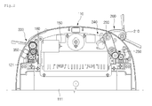
- Fig. 2 is a view of a state in which a cover of the automatic cleaner is separated according to an embodiment
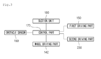
- Fig. 3 is a block diagram of the automatic cleaner according to an embodiment.
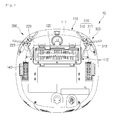
- an automatic cleaner 10 includes a casing 110 defining an exterior thereof.
- the casing 110 has a flat polyhedral shape, the present disclosure is not limited to the shape of the casing 110.
- a suction unit 180 for suctioning foreign substances and a dust collection unit (not shown) for collecting the suctioned foreign substances may be disposed within the casing 110.
- the casing 110 may include a base 111 and a cover (not shown) coupled to an upper portion of the base 111.
- a suction hole 112 is defined in a bottom surface of the casing 110.
- the suction hole 112 may serve as an inlet for suctioning foreign substances into the casing 110, substantially, the dust collection unit by using the suction unit 180.
- the suction hole 112 may be formed by cutting a portion of the bottom surface of the casing 110.
- a main brush 120 is disposed at a position corresponding to the suction hole 112 within the casing 110.
- the main brush 120 may pass through the suction hole 112 to contact the foreign substances on the floor surface, thereby removing the foreign substances.
- the main brush 120 is rotatably disposed on the casing 110.
- a first driving part 150 generating driving force for rotating the main brush 120 is disposed on the casing 110.
- the power of the first driving part 150 may be transmitted into the main brush 120 by a first power transmission part 160.
- a moving unit for moving the casing 110 may be disposed on the casing 110.
- the moving unit may include a wheel driving part 142 disposed within the casing 110 and a plurality of wheels that rotate by the wheel driving part 142.
- the driving part 142 may include a motor having the same number as that of the wheels 140.
- the side brush assembles 200 and 300 may include a first side brush assembly 200 disposed on one side of a front portion of the casing 110 and a second side brush assembly 300 disposed on the other side of the front portion of the casing 110.
- the second side brush assembly 300 may be omitted in the current embodiment.
- Each of the side brush assembles 200 and 300 may suction foreign substances existing in a region corresponding to the outside of the suction hole 112 through the suction hole 112.
- the casing 110 may further include a second driving part 230 generating power for moving the operable member 210 and a second power transmission part 240 for transmitting the power of the second driving part 230 into the operable member 210.
- the casing 110 may further include a third power transmission part 250 for transmitting the rotation force of the main brush 120 into the first side brush 220.
- the first side brush 220 receives the power generated in the first driving part 150 to rotate, and the operable member 210 receives the power generated in the second driving part 230 to rotate.
- the casing 11 may further include a fourth power transmission part 350 for transmitting the rotation force of the main brush 120 into the second side brush 310.
- the fourth power transmission part 350 may also be omitted.
- the first power transmission part 160 and the fourth power transmission part 350 may be connected to a rotation shaft 121 of the main brush 120. Also, the third power transmission part 350 may be connected to the rotation shaft 121 of the main brush 120.
- the first and second side brushes 220 and 310 rotate together with the main brush 120. Also, when the second driving part 230 is turned on, the operable member 210 may move.
- the present disclosure is not limited thereto.
- the power of the first driving part 150 may be transmitted into the first side brush 220 through only the third power transmission part 250.
- the power of the first driving part 150 is transmitted into the second side brush 310 by the main brush 120 and the fourth power transmission part 350 in Fig. 2 , the present disclosure is not limited thereto.
- the power of the first driving part 150 may be transmitted into the second side brush 310 through only the fourth power transmission part 350.
- the automatic cleaner 10 may further include a control part 170 for controlling an overall operation thereof and an obstacle sensor 190 for sensing an obstacle.
- the control part 170 may control the wheel driving part 142 and the second driving part 230 on the basis of information sensed by the obstacle sensor 190.
- control part 170 may recognize an obstacle, e.g. a corner on the basis of the information sensed by the obstacle sensor 190.
- control part 170 may control an operation of the second driving part 230.
- An infrared sensor, an ultrasonic sensor, an optical sensor, and the like may be used as the obstacle sensor 190.
- the current embodiment is not limited to a kind or number of obstacle sensor. Also, since the obstacle sensor may be realized by known technologies, detailed descriptions thereof will be omitted.
- the first power transmission part 160 may include a plurality of gears 161, 162, 163, and 164.
- a gear, which initially receives the power, of the plurality of gears may be referred to as a driving gear
- at least one gear connected to the driving gear may be referred to as an intermediate gear
- a gear, which finally receives the power, of the plurality of gears may be referred to as a driven gear.
- the intermediate gear may be omitted.
- the gears for transmitting the power are not limited to kind thereof.
- the driven gear 164 of the plurality of gears 161 to 164 may be connected to the rotation shaft 121 of the main brush 160.
- the power of the first driving part 150 may be transmitted into the rotation shaft 121 of the main brush 120 by the plurality of gears 161 to 164 to rotate the main brush 120.
- the fourth power transmission part 350 may include a plurality of gears 351, 352, 353, and 354.
- the driven gear 351 of the plurality of gears 351 to 354 may be connected to the rotation shaft 121 of the main brush 120.
- the driving gear 351 may be directly connected to a rotation shaft of the first driving part 151 or may be connected to one of the plurality of gears 161 to 164 constituting the first power transmission part 160.
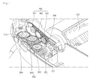
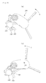
- Fig. 5 is a view of the second power transmission part and the third power transmission part according to an embodiment
- Fig. 6 is an exploded perspective view of the second power transmission part and the third power transmission part according to an embodiment
- Fig. 7 is a perspective view of a state in which the second power transmission part is connected to the operable member according to an embodiment.
- the second driving part 230 may be disposed on the casing 110.
- the second power transmission part 240 may include a first transmission member 241 connected to a rotation shaft 231 of the second driving part 230 and a second transmission member 248 connected to the first transmission member 241 and the operable member 210.
- the second transmission member 248 may be directly connected to the first transmission member 241 or indirectly connected to the first transmission member 241 by the other transmission member.
- a shaft connection part 243 connected to the rotation shaft 231 of the second driving part 230 may be disposed on the first transmission member 241.
- a first connection hinge 242 may be disposed on the first transmission member 241.
- the second transmission member 248 may be rotatably connected to the first connection hinge 242.
- the first connection hinge 242 may be disposed on the second transmission member 248, and the first transmission member 241 may be rotatably connected to the first connection hinge 242.
- a second connection hinge 211 may be disposed on the outside of the operable member 210. Also, the second transmission member 248 may be rotatably connected to the second connection hinge 211. For another example, the second connection hinge 211 may be disposed on the second transmission member 248, and the operable member 210 may be rotatably connected to the second connection hinge 211.
- a protrusion 245 may be disposed on the first transmission member 241.
- a plurality of slits 246A, 246B, and 246C may be disposed spaced apart from each other on the protrusion 245.
- the second driving part 230 When the second driving part 230 is turned on, the first transmission member 241 may rotate in one direction. As the first transmission member 241 rotates, the protrusion 245 may also rotate together with the first transmission member 241.
- the rotation of the protrusion 245 may be sensed by the sensing part 400.
- a photo interrupter sensor may be used as the sensing part 400.
- the current embodiment is not limited to a kind of sensing part 400. For example, various sensors such as a micro switch and the like may be applied to the current embodiment.
- the control part 170 may control the second driving part 230 on the basis of an output signal of the sensing part 400 according to the rotation of the protrusion 245.
- the operable member 210 may be limited in rotation range. That is, in the current embodiment, the sensing part 400 and the protrusion 245 may be referred to as rotation range restriction parts for restricting the rotation range of the operable member 210.
- the protrusion 245 may be disposed on the operable member 210. In this case, the operable member may be limited in rotation range on the basis of an output signal of the sensing part 400 according to the rotation of the operable member 210.
- the plurality of slits may include a first slit 246A, a second slit 246B, and at least one third slit 246C between the first and second slits 246A and 246B.
- an angle between the first and second slits 246A and 246B may be greater than that between the first and third slits 246A and 246C.
- a signal A is outputted from.
- a signal B different from the signal A may be outputted.
- the second driving unit 230 may be turned off.
- the sensing part 400 may be in a state of sensing the first slit 246A before the second driving part 230 is turned on.
- the protrusion 245 may rotate together with the first transmission member 241.
- the sensing part 400 senses the second slit 246B after sensing the third slit 246C during the rotation of the protrusion 245, the second driving part 230 may be turned off.
- the second driving part 230 may be turned off according to whether an obstacle exists at a corner, or a shape of the corner.
- a rotatable angle of the protrusion 245 may vary according to the number of slits 246A to 246C. That is, if a portion of the operable member 210 is referred to as a first position when the sensing part 400 senses the first slit 246A, and a position of the operable member 210 is referred to as a second position when the sensing part 400 senses the second slit 246B, the operable member 210 may move between the first position and the second position. Alternatively, the operable member 210 may be stopped at a point between the first and second positions. That is, the operable member 210 may be adjusted in rotation angle.
- the slits 246A to 246C may not be defined in the protrusion 245.
- a signal A may be outputted.
- a signal B may be outputted.
- a state before the second driving part 230 operates may be a state in which the sensing part 400 does not sense the protrusion 245.
- the protrusion 245 may rotate together with the first transmission member 241.
- the operable member 210 rotates in one direction (a first direction, i.e., a direction in which the operable member 210 is withdrawn from the casing) by the rotation of the first transmission member 241.
- the sensing part 400 senses the protrusion 245.
- the second driving part 230 may be turned off.
- Whether the operable member normally rotates may be determined by the protrusion 245 and the sensing part 400. This will be described later with reference to the accompanying drawings.
- a plurality of belts 256 and 262 may be further provided to reduce the number of gears.
- the driving gear 251 may be connected to a first intermediate gear 252, and the first intermediate gear 252 may be connected to a second intermediate gear 253.
- the second intermediate gear 253 may be connected to a third intermediate gear 254.
- the first belt 256 may connect the third intermediate gear 254 to the fourth intermediate gear 255.
- the driving gear 251, the first to fourth intermediate gears 252 to 255, and the first belt 256 may be disposed within gear housings 257 and 258.
- the fourth intermediate gear 255 may be coaxially connected to a fifth intermediate gear 260.
- the fifth intermediate gear 260 and the driven gear 261 may be connected to each other by the second belt 262.
- the driven gear 261 may be connected to the second side brush 220.
- the gear shaft of the driven gear 261 may serve as a rotation shaft of the second side brush 220, or the rotation shaft 223 of the second side brush 220 may be coupled to the driven gear 261.
- the fifth intermediate gear 260, the driven gear 261, and the second belt 262 may be disposed within the operable member 210. Also, the operable member 210 may further include a cover 212.
- a hole through which the fourth intermediate gear 255 passes may be defined in the cover 212.
- a connection part 213 rotatably connected to the gear housings 257 and 258 may be disposed around the hole 214 on the cover 212.
- the connection part 213 may serve as a rotation shaft of the operable member 210.
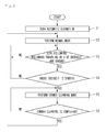
- Fig. 8 is a flowchart illustrating a method for controlling the automatic cleaner according to an embodiment
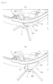
- Fig. 9 is a view illustrating an operation state of a first side brush assembly.
- Fig. 9A and 10A are views illustrating a state in which a first side brush assembly operates in a normal mode
- Figs. 9B and 10B are views illustrating a state in which the first side brush assembly operates in a corner cleaning mode.
- the automatic cleaner is turned on to clean a surface to be cleaned (for example, a floor surface) by using the automatic cleaner (S1).
- the automatic cleaner may automatically operate in a normal mode or operate in the normal mode by an input of a starting command (S2).
- the automatic cleaner performs cleaning while moving by the moving unit.
- the first driving part 150 In the normal mode, the first driving part 150 is turned on. When the first driving part 150 is turned on, the power of the first driving part 150 may be transmitted into the main brush 120 by the first power transmission part 160. Thus, the main brush 120 may rotate.
- the power of the first driving part 150 may be transmitted into the first side brush 220 by the third power transmission part 250 and transmitted into the second side brush 310 by the fourth power transmission part 350.
- the first and second side brushes 220 and 310 may rotate.
- the first side brush 220 rotates in a direction A.
- the control part 170 determines whether a corner is recognized (S3 and S4). In detail, the control part 170 determines whether the automatic cleaner 10 performs a wall following traveling (senses a wall) or whether a side obstacle is sensed (S3).
- the wall following traveling may represent that the automatic cleaner travels along the wall.
- Whether the wall following traveling is performed, or the side obstacle is sensed may be determined on the basis of information sensed by the obstacle sensor 190.
- the control part 170 may determine whether a front obstacle (or a front wall) is sensed (S4).
- the corner may correspond to a portion at which a plurality of planes (that is not limited thereto) meet each other, the control part 150 determines that the corner is sensed in the case where the wall or the side and front surfaces are sensed.
- control part 170 controls the automatic cleaner 10 so that the automatic cleaner 10 performs a corner cleaning mode (S5).
- the control part 170 turns the second driving part 230 on.
- the operable member 210 may move from the state (the first position) of Fig. 9A to the state (the second position) of Fig. 9B (may rotate).
- the rotation shaft 223 of the first side brush 220 may move in a horizontal direction.
- the second driving part 230 is turned off in a state where the operable member 210 rotates at a predetermined angle.
- an operation type of the first side brush assembly (or the operable member) in the normal mode is referred to as a first type
- an operation type (including a position and operation pattern) of the first side brush assembly (or the operable member) in the corner cleaning mode may be referred to as a second type.
- the first side brush assembly may be changed from the first type into the second type in the corner cleaning mode.
- the first transmission member 241 rotates.
- the first connection hinge 242 disposed on the first transmission member 241 may move.
- the second transmission member 248 may move, and thus, the second connection hinge 211 may move by the moving of the second transmission member 248. Therefore, the operable member 210 may rotate by the second connection hinge 211.
- the first type of the first side brush assembly may be in a state in which the operable member 210 is not withdrawn (i.e., the operable member 210 is disposed at the first position), and the second type of the first side brush assembly may be in a state in which the operable member 210 is withdrawn and then stopped (i.e., the operable member 210 is disposed at the second position).
- a portion of the operable member 210 may be disposed within the casing 110, and then, the operable member 210 may protrude to the outside of the casing 110 by the rotation thereof. That is, the operable member 210 may protrude to the outside of the case 110 by the rotation thereof from a state in which the operable member 210 overlaps the casing 110 as shown in Fig. 9A .
- a vertically overlapping area between the operable member 210 and the casing 110 may be reduced when compared to a state before the operable member 210 protrudes to the outside of the casing 110.
- the corner cleaning may be effectively performed.
- the second type of the first side brush assembly 200 may include a process in which the operable member 210 is repeatedly changed from the first position into the second position and from the second position into the first position. That is, the operable member 210 may repeatedly move between the first position and the second position.
- the second driving part 230 is turned on to operate in one direction and then is turned off. Then, the second driving part 230 is turned again on to operate in the other direction and then is turned off.
- the above-described processes may be repeatedly performed.
- the process in which the operable member 210 moves from the first position to the second position and then is stopped or moves from the second position to the first position may be achieved by the above-described sensing part 400 and the protrusion 245.
- the stopped state of the moving unit may be maintained in the corner cleaning mode.
- the control part 170 determines whether the corner is completely cleaned (S6). For example, it is determined that the corner is completely cleaned when a time at which the operation time of the first side brush assembly 200 is changed exceeds a reference time, the rotation number of the first side brush (or the second driving part) exceeds a reference number after the operation type of the first side brush assembly 200 is changed, an operation time of the second driving part exceeds a reference time, or the changed number of operation type exceeds a reference number.
- whether corner is completely cleaned may be determined on the basis of a sensor for sensing the cleaning state. For example, whether the corner is completely cleaned may be determined on the basis of images of the corner photographed by a camera or determined through an amount of dusts suctioned through the suction hole by using the sensor.
- the present disclosure is not limited to the methods for determining whether the corner is completely cleaned.
- the automatic cleaner 10 when it is determined that the corner is completely cleaned, the automatic cleaner 10 operates again in the normal mode. That is, the operation type of the first side brush assembly may be changed in the second type into the first type.
- the corner may be effectively cleaned by the first side brush assembly.
- damage of the first side brush and inconvenience in storage of the first side brush assembly may be prevented.
- Fig. 11 is a flowchart illustrating a method for controlling the automatic cleaner according to whether the first side brush normally rotates according to an embodiment.
- the automatic cleaner is turned on to clean a surface to be cleaned (for example, a floor surface) by using the automatic cleaner (S11).
- the automatic cleaner may automatically operate in a normal mode or operate in the normal mode by an input of a starting command (S12).
- the automatic cleaner performs cleaning while moving by the moving unit.
- the main brush 120 and the first and second side brushes 220 and 310 rotate.
- the control part 170 determines whether a corner is recognized (S13 and S14). In detail, the control part 170 determines whether the automatic cleaner 10 performs a wall following traveling (senses a wall surface) or whether a side obstacle is sensed (S13). The wall following traveling may represent that the automatic cleaner travels along the wall.
- Whether the wall following traveling is performed, or the side obstacle is sensed may be determined on the basis of information sensed by the obstacle sensor 190.
- the control part 170 may determine whether a front obstacle (or a front wall) is sensed (S14). In general, since the corner may correspond to a portion at which a plurality of planes (that is not limited thereto) meet each other, the control part 150 determines that the corner is sensed in the case where the wall or the side and front surfaces are sensed.
- control part 170 turns the second driving part 230 on (S15).
- the fist transmission member connected to the second driving part 230 may rotate.
- the first transmission member 241 rotates, since the protrusion 245 may rotate together with the first transmission member 241.
- the sensing part 400 may sense the rotation of the protrusion 245.
- the operable member 210 may also rotate.
- control part 170 determines whether the operable member 210 normally operates on the basis of information with respect to the protrusion 245 sensed by the sensing part 400 (S16).
- the sensing part 400 may sense a first slit 246A of the protrusion 245. This is done because the second driving part 230 is turned off in the state where the first slit 246A of the protrusion 245 is sensed. Then, when the second driving part 230 is turned on, since the protrusion 245 rotates, the sensing part 400 may not sense the first slit 246A. When the first slit 246A is continuously sensed, or the third or second slit 246C or 246B is not sensed until a predetermined time elapses after the second driving part 230 is turned on, the control part 170 may determine that the operable member 210 does not normally operate. On the other hand, when the second driving part 230 is turned on, and then the third or second slit 246C or 246C is sensed until a predetermined time elapses, the control part 170 may determine that the operable member 210 normally operates.
- the case in which the operable member 210 does not normally operate may be a case in which the power of the second driving part 230 is not smoothly transmitted into the operable member 210 through the second power transmission part 240 (an internal factor) or a case in which the operable member 210 does not rotate by an obstacle outside the automatic cleaner 10 even though the power of the second driving part 230 is smoothly transmitted into the operable member 210 through the second power transmission part 240.
- a state before the second driving part 230 is turned on may be a state in which the sensing part 40 does not sense the protrusion 245.
- the sensing part 245 may rotate and also sense the protrusion 245.
- the control part 170 may determine that the operable member 210 does not normally operate.
- the control part 170 determines whether the corner is completely cleaned (S18). For example, it is determined that the corner is completely cleaned when a time at which the operation time of the first side brush assembly 200 is changed exceeds a reference time, the rotation number of the first side brush (or the second driving part) exceeds a reference number after the operation type of the first side brush assembly 200 is changed, an operation time of the second driving part exceeds a reference time, or the changed number of operation type exceeds a reference number.
- whether corner is completely cleaned may be determined on the basis of a sensor for sensing the cleaning state. For example, whether the corner is completely cleaned may be determined on the basis of images of the corner photographed by a camera or determined through an amount of dusts suctioned through the suction hole by using the sensor.
- the present disclosure is not limited to the methods for determining whether the corner is completely cleaned.
- control part 170 determines again whether the operable member normally operates (S20). If the operable member 210 normally operates, the process proceeds to the operation S17 to perform corner cleaning.
- the control part 170 controls the wheel driving part 142 (the moving unit) so that the automatic cleaner 10 evades the corner (S21). For example, the automatic cleaner 10 may go into reverse from the present position and then be changed in direction to move away from the corner. Also, the control part 170 controls the second driving part 230 so that the operable member 210 is in the inserted state.
- error information may be displayed on a display unit (not shown). Also, information with respect to the position (the corner) at which an error occurs may be stored in a map of a memory (not shown).
- the automatic cleaner 10 operates again in the normal mode.
- the automatic cleaner 10 may move to the error occurrence position stored in the map when the cleaning is performed in the normal mode to perform the corner cleaning mode again.
- the corner cleaning performance may be improved.
- the error information is displayed when the corner cleaning is not performed, the user may confirm the state of the automatic cleaner or the corner state.
Abstract

Description
- In general, cleaner are home appliances that suction foreign substances on the floor surface to remove the foreign substances from the floor surface. In recent years, cleaners for automatically performing cleaning among the cleaners are called automatic cleaners. Such an automatic cleaner may suction foreign substances on the floor surface to remove the foreign substances while moving by driving force of a motor that operates by a rechargeable battery.
- A moving device is installed on a casing that defines an exterior of a general automatic cleaner. Also, the automatic cleaner suctions foreign substances on the floor surface while moving in a predetermined direction by the moving device. For this, a suction hole for suctioning the foreign substances on the floor surface is formed in a bottom surface of the casing. Also, a main brush that directly contacts the foreign substances to suction the foreign substances through the suction hole may be disposed on the suction hole.
- However, the automatic cleaner may suction only foreign substances existing in a region that corresponds to a lower side of the casing, substantially, a region that corresponds to a lower side of the suction hole. Thus, in case of a region corresponding to the outside of the suction hole, the cleaning may not be completely performed.
- To prevent this phenomenon from occurring, a side brush may be disposed on the bottom surface of the casing. At least one portion of the side brush extends to the outside of the casing.
- Also, the side brush may rotate with respect to the casing to sweep foreign substances in a region corresponding to the outside of the casing, substantially, the suction hole toward the suction hole.
- However, the automatic cleaner according to the related art may have following limitations.
- As described above, the side brush may rotate to suction the foreign substances in the region corresponding to the outside of the suction hole through the suction hole. Thus, as the side brush increases in length, a region to be cleaned by the automatic cleaner may substantially increase. However, if the side brush increases in length, the side brush may be damaged during the cleaning or the storage of the side brush. Also, if the side brush increase in length, a region occupied by the automatic cleaner may increase. As a result, the automatic cleaner may be inconvenient in storage.
- In one embodiment, an automatic cleaner includes: a casing having a suction hole; a main brush disposed on a side of the suction hole within the casing; and a first driving part arranged to rotate the main brush; characterized in that the automatic cleaner further comprising: an operable member movably disposed on the casing; a second driving part arranged to generate power for moving the operable member; a side brush rotatably disposed on the operable member to receive power of the first driving part; and a control part arranged to control the first and second driving parts.
- The control part turns the second driving part after turning the second driving part on.
- The control part turns the first driving part on in a normal mode, and when an obstacle is sensed, the control part additionally turns the second driving part on.
- The automatic cleaner further comprises a sensing part arranged to sense the movement of the operable member, wherein the control part controls the second driving part so that the operable member moves in one direction when the obstacle is sensed, and when an abnormal operation of the operable member is sensed by the sensing part after the second driving part is turned on, the control part controls the second driving part so that the operable member moves in the other direction.
- The automatic cleaner further comprises a moving unit disposed on the casing to move the casing; and a sensing part arranged to sense the movement of the operable member, wherein the control part controls the second driving part so that the operable member moves in one direction when the obstacle is sensed, and when an abnormal operation of the operable member is sensed by the sensing part after the second driving part is turned on, the control part controls the moving unit so that the automatic cleaner evades the obstacle.
- The automatic cleaner further comprises a first power transmission part arranged to transmit the power of the first driving part into the main brush; a second power transmission part arranged to transmit the power of the second driving part into the operable member; and a third power transmission part arranged to transmit the rotation force of the main brush into the side brush.
- The automatic cleaner further comprises a first power transmission part arranged to transmit the power of the first driving part into the main brush; a second power transmission part arranged to transmit the power of the second driving part into the operable member; and a third power transmission part arranged to transmit the power of the first driving part into the side brush.
- The automatic cleaner further comprises an additional side brush rotatably disposed on the casing; and a fourth power transmission part arranged to transmit the power of the first driving part into the additional side brush.
- The automatic cleaner further comprises an additional side brush rotatably disposed on the casing; and a fourth power transmission part arranged to transmit the rotation force of the main brush into the additional side brush.
- The automatic cleaner further comprises a rotation range restriction part arranged to restrict a rotation range of the operable member.
- The rotation range restriction part comprises a portion of components of the second power transmission part or a sensing part arranged to sense the rotation of the operable member.
- The operable member moves from a first position to a second position and then is stopped by the rotation range restriction part.
- The operable member is reciprocated between a first position and a second position by the rotation range restriction part.
- The operable member moves within a range of a first position to a second position and be stopped at a predetermined position between the first and second positions by the rotation range restriction part.
- When the operable member moves, a rotation shaft of the side brush moves in a horizontal direction.
- In another embodiment, an automatic cleaner includes: a casing having a suction hole; a moving unit disposed on the casing to move the casing; an operable member movably disposed on the casing; a side brush rotatably disposed on the operable member; a first driving part arranged to generate power for moving the side brush; a second driving part arranged to generate power for moving the operable member; a sensing part arranged to sense the movement of the operable member; and a control part arranged to control the second driving part on the basis of information sensed by the sensing part.
- The control part may control the second driving part so that the operable member moves in one direction when the corner is sensed, and when an abnormal operation of the operable member is sensed by the sensing part after the second driving part is turned on, the control part may control the second driving part so that the operable member moves in the other direction.
- The control part may control the second driving part so that the operable member moves in one direction when the corner is sensed, and when an abnormal operation of the operable member is sensed by the sensing part after the second driving part is turned on, the control part may control the moving unit so that the automatic cleaner evades the corner.
- The details of one or more embodiments are set forth in the accompanying drawings and the description below. Other features will be apparent from the description and drawings, and from the claims.
-
-
Fig. 1 is a bottom surface of an automatic cleaner according to an embodiment. -
Fig. 2 is a view of a state in which a cover of the automatic cleaner is separated according to an embodiment. -
Fig. 3 is a block diagram of the automatic cleaner according to an embodiment. -
Fig. 4 is a view of a first power transmission part and a fourth power transmission part according to an embodiment. -
Fig. 5 is a view of a second power transmission part and a third power transmission part according to an embodiment. -
Fig. 6 is an exploded perspective view of the second power transmission part and the third power transmission part according to an embodiment. -
Fig. 7 is a perspective view of a state in which the second power transmission part is connected to an operable member according to an embodiment. -
Fig. 8 is a flowchart illustrating a method for controlling the automatic cleaner according to an embodiment. -
Figs. 9 and10 are views illustrating an operation state of a first side brush assembly, whereinFig. 9A and10A are views illustrating a state in which a first side brush assembly operates in a normal mode, andFigs. 9B and10B are views illustrating a state in which the first side brush assembly operates in a corner cleaning mode. -
Fig. 11 is a flowchart illustrating a method for controlling an automatic cleaner according to whether the first side brush normally rotates according to an embodiment. - Reference will now be made in detail to the embodiments of the present disclosure, examples of which are illustrated in the accompanying drawings.
- In the following detailed description of the preferred embodiments, reference is made to the accompanying drawings that form a part hereof, and in which is shown by way of illustration specific preferred embodiments in which the invention may be practiced. These embodiments are described in sufficient detail to enable those skilled in the art to practice the invention, and it is understood that other embodiments may be utilized and that logical structural, mechanical, electrical, and chemical changes may be made without departing from the spirit or scope of the invention. To avoid detail not necessary to enable those skilled in the art to practice the invention, the description may omit certain information known to those skilled in the art. The following detailed description is, therefore, not to be taken in a limiting sense.
-
Fig. 1 is a bottom surface of an automatic cleaner according to an embodiment,Fig. 2 is a view of a state in which a cover of the automatic cleaner is separated according to an embodiment, andFig. 3 is a block diagram of the automatic cleaner according to an embodiment. - Referring to
Figs. 1 to 3 , anautomatic cleaner 10 according to an embodiment includes acasing 110 defining an exterior thereof. Although thecasing 110 has a flat polyhedral shape, the present disclosure is not limited to the shape of thecasing 110. - Various parts constituting the
automatic cleaner 10 may be installed within thecasing 110. For example, asuction unit 180 for suctioning foreign substances and a dust collection unit (not shown) for collecting the suctioned foreign substances may be disposed within thecasing 110. Thecasing 110 may include abase 111 and a cover (not shown) coupled to an upper portion of thebase 111. - Also, a
suction hole 112 is defined in a bottom surface of thecasing 110. Thesuction hole 112 may serve as an inlet for suctioning foreign substances into thecasing 110, substantially, the dust collection unit by using thesuction unit 180. Thesuction hole 112 may be formed by cutting a portion of the bottom surface of thecasing 110. - A
main brush 120 is disposed at a position corresponding to thesuction hole 112 within thecasing 110. Themain brush 120 may pass through thesuction hole 112 to contact the foreign substances on the floor surface, thereby removing the foreign substances. Themain brush 120 is rotatably disposed on thecasing 110. - A
first driving part 150 generating driving force for rotating themain brush 120 is disposed on thecasing 110. The power of thefirst driving part 150 may be transmitted into themain brush 120 by a firstpower transmission part 160. - Also, a moving unit for moving the
casing 110 may be disposed on thecasing 110. The moving unit may include awheel driving part 142 disposed within thecasing 110 and a plurality of wheels that rotate by thewheel driving part 142. In the current embodiment, the drivingpart 142 may include a motor having the same number as that of thewheels 140. - One or more side brush assembles 200 and 300 may be disposed on a lower portion of the
casing 110. In the current embodiment, a structure in which the plurality of side brush assembles 200 and 300 are disposed on thecasing 110 will be described as an example. - The side brush assembles 200 and 300 may include a first
side brush assembly 200 disposed on one side of a front portion of thecasing 110 and a secondside brush assembly 300 disposed on the other side of the front portion of thecasing 110. However, the secondside brush assembly 300 may be omitted in the current embodiment. - The first
side brush assembly 200 may include afirst side brush 220 rotated (revolved) with respect to afirst rotation shaft 223. Thefirst side brush 220 may be rotatably disposed on anoperable member 210. - The second
side brush assembly 300 may include asecond side brush 310 rotated (revolved) with respect to asecond rotation shaft 313. - The
first side brush 220 may include afirst brush holder 221 and a plurality of first brush bristles 222 disposed on thefirst brush holder 221. Thesecond side brush 310 may include asecond brush holder 311 and a plurality of second brush bristles 312 disposed on thesecond brush holder 311. - The first
side brush assembly 200 may be disposed on the lower portion of thecasing 110. Alternatively, at least one portion of the firstside brush assembly 200 may be disposed within thecasing 110, and the other portion of the firstside brush assembly 200 may be disposed on the outside of thecasing 110. For example, the firstside brush assembly 200 may rotatably operate. - Each of the side brush assembles 200 and 300 may suction foreign substances existing in a region corresponding to the outside of the
suction hole 112 through thesuction hole 112. - The
casing 110 may further include asecond driving part 230 generating power for moving theoperable member 210 and a secondpower transmission part 240 for transmitting the power of thesecond driving part 230 into theoperable member 210. - Also, the
casing 110 may further include a thirdpower transmission part 250 for transmitting the rotation force of themain brush 120 into thefirst side brush 220. - That is, the
first side brush 220 receives the power generated in thefirst driving part 150 to rotate, and theoperable member 210 receives the power generated in thesecond driving part 230 to rotate. - Also, the casing 11 may further include a fourth
power transmission part 350 for transmitting the rotation force of themain brush 120 into thesecond side brush 310. However, when the secondside brush assembly 300 is omitted, the fourthpower transmission part 350 may also be omitted. - The first
power transmission part 160 and the fourthpower transmission part 350 may be connected to arotation shaft 121 of themain brush 120. Also, the thirdpower transmission part 350 may be connected to therotation shaft 121 of themain brush 120. - Thus, when the
first driving part 150 is turned on, the first and second side brushes 220 and 310 rotate together with themain brush 120. Also, when thesecond driving part 230 is turned on, theoperable member 210 may move. - Although the power of the
first driving part 150 is transmitted into thefirst side brush 220 by themain brush 120 and the thirdpower transmission part 250 inFig. 2 , the present disclosure is not limited thereto. For example, the power of thefirst driving part 150 may be transmitted into thefirst side brush 220 through only the thirdpower transmission part 250. - Also, although the power of the
first driving part 150 is transmitted into thesecond side brush 310 by themain brush 120 and the fourthpower transmission part 350 inFig. 2 , the present disclosure is not limited thereto. For example, the power of thefirst driving part 150 may be transmitted into thesecond side brush 310 through only the fourthpower transmission part 350. - The
automatic cleaner 10 may further include acontrol part 170 for controlling an overall operation thereof and anobstacle sensor 190 for sensing an obstacle. Thecontrol part 170 may control thewheel driving part 142 and thesecond driving part 230 on the basis of information sensed by theobstacle sensor 190. - Particularly, the
control part 170 may recognize an obstacle, e.g. a corner on the basis of the information sensed by theobstacle sensor 190. When thecontrol part 170 recognizes the obstacle, thecontrol part 170 may control an operation of thesecond driving part 230. - An infrared sensor, an ultrasonic sensor, an optical sensor, and the like may be used as the
obstacle sensor 190. The current embodiment is not limited to a kind or number of obstacle sensor. Also, since the obstacle sensor may be realized by known technologies, detailed descriptions thereof will be omitted. -
FIG. 4 is a view of the first power transmission part and the fourth power transmission part according to an embodiment. - Referring to
Fig. 4 , the firstpower transmission part 160 may include a plurality ofgears - In this specification, a gear, which initially receives the power, of the plurality of gears may be referred to as a driving gear, at least one gear connected to the driving gear may be referred to as an intermediate gear, and a gear, which finally receives the power, of the plurality of gears may be referred to as a driven gear. Here, in this specification, the intermediate gear may be omitted. Also, in this specification, the gears for transmitting the power are not limited to kind thereof.
- The driven
gear 164 of the plurality ofgears 161 to 164 may be connected to therotation shaft 121 of themain brush 160. Thus, when thefirst driving part 150 operates, the power of thefirst driving part 150 may be transmitted into therotation shaft 121 of themain brush 120 by the plurality ofgears 161 to 164 to rotate themain brush 120. - The fourth
power transmission part 350 may include a plurality ofgears gear 351 of the plurality ofgears 351 to 354 may be connected to therotation shaft 121 of themain brush 120. For another example, thedriving gear 351 may be directly connected to a rotation shaft of the first driving part 151 or may be connected to one of the plurality ofgears 161 to 164 constituting the firstpower transmission part 160. -
Fig. 5 is a view of the second power transmission part and the third power transmission part according to an embodiment,Fig. 6 is an exploded perspective view of the second power transmission part and the third power transmission part according to an embodiment, andFig. 7 is a perspective view of a state in which the second power transmission part is connected to the operable member according to an embodiment. - Referring to
Figs. 5 to 7 , thesecond driving part 230 may be disposed on thecasing 110. The secondpower transmission part 240 may include afirst transmission member 241 connected to arotation shaft 231 of thesecond driving part 230 and asecond transmission member 248 connected to thefirst transmission member 241 and theoperable member 210. Thesecond transmission member 248 may be directly connected to thefirst transmission member 241 or indirectly connected to thefirst transmission member 241 by the other transmission member. - A
shaft connection part 243 connected to therotation shaft 231 of thesecond driving part 230 may be disposed on thefirst transmission member 241. Also, afirst connection hinge 242 may be disposed on thefirst transmission member 241. Thesecond transmission member 248 may be rotatably connected to thefirst connection hinge 242. For another example, thefirst connection hinge 242 may be disposed on thesecond transmission member 248, and thefirst transmission member 241 may be rotatably connected to thefirst connection hinge 242. - A
second connection hinge 211 may be disposed on the outside of theoperable member 210. Also, thesecond transmission member 248 may be rotatably connected to thesecond connection hinge 211. For another example, thesecond connection hinge 211 may be disposed on thesecond transmission member 248, and theoperable member 210 may be rotatably connected to thesecond connection hinge 211. - A
protrusion 245 may be disposed on thefirst transmission member 241. A plurality ofslits protrusion 245. When thesecond driving part 230 is turned on, thefirst transmission member 241 may rotate in one direction. As thefirst transmission member 241 rotates, theprotrusion 245 may also rotate together with thefirst transmission member 241. The rotation of theprotrusion 245 may be sensed by thesensing part 400. For example, a photo interrupter sensor may be used as thesensing part 400. However, the current embodiment is not limited to a kind ofsensing part 400. For example, various sensors such as a micro switch and the like may be applied to the current embodiment. - The
control part 170 may control thesecond driving part 230 on the basis of an output signal of thesensing part 400 according to the rotation of theprotrusion 245. As thecontrol part 170 controls thesecond driving part 230, theoperable member 210 may be limited in rotation range. That is, in the current embodiment, thesensing part 400 and theprotrusion 245 may be referred to as rotation range restriction parts for restricting the rotation range of theoperable member 210. Here, theprotrusion 245 may be disposed on theoperable member 210. In this case, the operable member may be limited in rotation range on the basis of an output signal of thesensing part 400 according to the rotation of theoperable member 210. - For example, in the current embodiment, the plurality of slits may include a
first slit 246A, asecond slit 246B, and at least onethird slit 246C between the first andsecond slits - Thus, an angle between the first and
second slits third slits - Also, when the
sensing part 400 senses each of theslits sensing part 400 senses theprotrusion 245, a signal B different from the signal A may be outputted. - Also, when the
second driving part 230 is turned on, and then thesensing part 400 senses one of theslits second driving unit 230 may be turned off. - For example, the
sensing part 400 may be in a state of sensing thefirst slit 246A before thesecond driving part 230 is turned on. When thesecond driving part 230 is turned on, theprotrusion 245 may rotate together with thefirst transmission member 241. When thesensing part 400 senses thesecond slit 246B after sensing thethird slit 246C during the rotation of theprotrusion 245, thesecond driving part 230 may be turned off. - For another example, when the
sensing part 400 senses the third slit 246c, thesecond driving part 230 may be turned off according to whether an obstacle exists at a corner, or a shape of the corner. - Thus, a rotatable angle of the
protrusion 245 may vary according to the number ofslits 246A to 246C. That is, if a portion of theoperable member 210 is referred to as a first position when thesensing part 400 senses thefirst slit 246A, and a position of theoperable member 210 is referred to as a second position when thesensing part 400 senses thesecond slit 246B, theoperable member 210 may move between the first position and the second position. Alternatively, theoperable member 210 may be stopped at a point between the first and second positions. That is, theoperable member 210 may be adjusted in rotation angle. - For another example, the
slits 246A to 246C may not be defined in theprotrusion 245. In this case, when thesensing part 400 does not sense theprotrusion 245, a signal A may be outputted. Also, when thesensing part 400 senses theprotrusion 245, a signal B may be outputted. For example, a state before thesecond driving part 230 operates may be a state in which thesensing part 400 does not sense theprotrusion 245. - Also, when the
second driving part 230 is turned on, theprotrusion 245 may rotate together with thefirst transmission member 241. Also, theoperable member 210 rotates in one direction (a first direction, i.e., a direction in which theoperable member 210 is withdrawn from the casing) by the rotation of thefirst transmission member 241. When theprotrusion 245 rotates, thesensing part 400 senses theprotrusion 245. Also, when theprotrusion 245 is not sensed by thesensing part 400 while thesensing part 400 senses theprotrusion 245, thesecond driving part 230 may be turned off. - Whether the operable member normally rotates may be determined by the
protrusion 245 and thesensing part 400. This will be described later with reference to the accompanying drawings. - The third
power transmission part 250 may include a plurality ofgears driving gear 251 of the plurality ofgears 251 to 261 may be connected to therotation shaft 121 of themain brush 120. For another example, thedriving gear 251 may be connected to the rotation shaft of thefirst driving part 150. - In the current embodiment, a plurality of
belts - In detail, the
driving gear 251 may be connected to a firstintermediate gear 252, and the firstintermediate gear 252 may be connected to a secondintermediate gear 253. The secondintermediate gear 253 may be connected to a thirdintermediate gear 254. Thefirst belt 256 may connect the thirdintermediate gear 254 to the fourthintermediate gear 255. Also, thedriving gear 251, the first to fourthintermediate gears 252 to 255, and thefirst belt 256 may be disposed withingear housings - The fourth
intermediate gear 255 may be coaxially connected to a fifthintermediate gear 260. Also, the fifthintermediate gear 260 and the drivengear 261 may be connected to each other by thesecond belt 262. Also, the drivengear 261 may be connected to thesecond side brush 220. Here, the gear shaft of the drivengear 261 may serve as a rotation shaft of thesecond side brush 220, or therotation shaft 223 of thesecond side brush 220 may be coupled to the drivengear 261. - The fifth
intermediate gear 260, the drivengear 261, and thesecond belt 262 may be disposed within theoperable member 210. Also, theoperable member 210 may further include acover 212. - A hole through which the fourth
intermediate gear 255 passes may be defined in thecover 212. Also, aconnection part 213 rotatably connected to thegear housings hole 214 on thecover 212. Thus, theconnection part 213 may serve as a rotation shaft of theoperable member 210. - The current embodiment is not limited to the number and shape of gears constituting the third
power transmission part 250. Also, the plurality ofbelts power transmission part 250. -
Fig. 8 is a flowchart illustrating a method for controlling the automatic cleaner according to an embodiment, andFig. 9 is a view illustrating an operation state of a first side brush assembly. Here,Fig. 9A and10A are views illustrating a state in which a first side brush assembly operates in a normal mode, andFigs. 9B and10B are views illustrating a state in which the first side brush assembly operates in a corner cleaning mode. - Referring to
Figs. 8 to 10 , the automatic cleaner is turned on to clean a surface to be cleaned (for example, a floor surface) by using the automatic cleaner (S1). - After the automatic cleaner is turned on, the automatic cleaner may automatically operate in a normal mode or operate in the normal mode by an input of a starting command (S2).
- In the normal mode of the automatic cleaner, the automatic cleaner performs cleaning while moving by the moving unit.
- In the normal mode, the
first driving part 150 is turned on. When thefirst driving part 150 is turned on, the power of thefirst driving part 150 may be transmitted into themain brush 120 by the firstpower transmission part 160. Thus, themain brush 120 may rotate. - Also, the power of the
first driving part 150 may be transmitted into thefirst side brush 220 by the thirdpower transmission part 250 and transmitted into thesecond side brush 310 by the fourthpower transmission part 350. Thus, the first and second side brushes 220 and 310 may rotate. For example, inFigs. 9A and10B , thefirst side brush 220 rotates in a direction A. - While the
automatic cleaner 10 operates in the normal mode, thecontrol part 170 determines whether a corner is recognized (S3 and S4). In detail, thecontrol part 170 determines whether theautomatic cleaner 10 performs a wall following traveling (senses a wall) or whether a side obstacle is sensed (S3). The wall following traveling may represent that the automatic cleaner travels along the wall. - Whether the wall following traveling is performed, or the side obstacle is sensed may be determined on the basis of information sensed by the
obstacle sensor 190. - After it is determined that the
automatic cleaner 10 performs the wall following traveling, or the side obstacle (or a sidewall) is sensed, thecontrol part 170 may determine whether a front obstacle (or a front wall) is sensed (S4). In general, since the corner may correspond to a portion at which a plurality of planes (that is not limited thereto) meet each other, thecontrol part 150 determines that the corner is sensed in the case where the wall or the side and front surfaces are sensed. - When it is determined that the corner is sensed in the operations S3 and S4, the
control part 170 controls theautomatic cleaner 10 so that theautomatic cleaner 10 performs a corner cleaning mode (S5). - In the corner cleaning mode, the
control part 170 turns thesecond driving part 230 on. When thesecond driving part 230 is turned on, theoperable member 210 may move from the state (the first position) ofFig. 9A to the state (the second position) ofFig. 9B (may rotate). When theoperable member 210 rotates, therotation shaft 223 of thefirst side brush 220 may move in a horizontal direction. Also, thesecond driving part 230 is turned off in a state where theoperable member 210 rotates at a predetermined angle. - If an operation type of the first side brush assembly (or the operable member) in the normal mode according to the current embodiment is referred to as a first type, an operation type (including a position and operation pattern) of the first side brush assembly (or the operable member) in the corner cleaning mode may be referred to as a second type. Also, the first side brush assembly may be changed from the first type into the second type in the corner cleaning mode.
- In detail, when the
second driving part 230 is turned on, thefirst transmission member 241 rotates. When thefirst transmission member 241 rotates, thefirst connection hinge 242 disposed on thefirst transmission member 241 may move. When thefirst connection hinge 242 moves, thesecond transmission member 248 may move, and thus, thesecond connection hinge 211 may move by the moving of thesecond transmission member 248. Therefore, theoperable member 210 may rotate by thesecond connection hinge 211. - As described above, the first type of the first side brush assembly may be in a state in which the
operable member 210 is not withdrawn (i.e., theoperable member 210 is disposed at the first position), and the second type of the first side brush assembly may be in a state in which theoperable member 210 is withdrawn and then stopped (i.e., theoperable member 210 is disposed at the second position). - For example, a portion of the
operable member 210 may be disposed within thecasing 110, and then, theoperable member 210 may protrude to the outside of thecasing 110 by the rotation thereof. That is, theoperable member 210 may protrude to the outside of thecase 110 by the rotation thereof from a state in which theoperable member 210 overlaps thecasing 110 as shown inFig. 9A . When theoperable member 210 protrudes to the outside of thecasing 110 by the rotation thereof, a vertically overlapping area between theoperable member 210 and thecasing 110 may be reduced when compared to a state before theoperable member 210 protrudes to the outside of thecasing 110. - When the
operable member 210 rotates to protrude to the outside of thecasing 110 in the corner cleaning mode, since thefirst side brush 220 disposed on theoperable member 210 is adjacent to the corner, the corner cleaning may be effectively performed. - For another example, in the corner cleaning mode, the second type of the first
side brush assembly 200 may include a process in which theoperable member 210 is repeatedly changed from the first position into the second position and from the second position into the first position. That is, theoperable member 210 may repeatedly move between the first position and the second position. In this case, thesecond driving part 230 is turned on to operate in one direction and then is turned off. Then, thesecond driving part 230 is turned again on to operate in the other direction and then is turned off. Here, the above-described processes may be repeatedly performed. - The process in which the
operable member 210 moves from the first position to the second position and then is stopped or moves from the second position to the first position may be achieved by the above-describedsensing part 400 and theprotrusion 245. - Also, the stopped state of the moving unit may be maintained in the corner cleaning mode.
- Then, the
control part 170 determines whether the corner is completely cleaned (S6). For example, it is determined that the corner is completely cleaned when a time at which the operation time of the firstside brush assembly 200 is changed exceeds a reference time, the rotation number of the first side brush (or the second driving part) exceeds a reference number after the operation type of the firstside brush assembly 200 is changed, an operation time of the second driving part exceeds a reference time, or the changed number of operation type exceeds a reference number. - Alternatively, whether corner is completely cleaned may be determined on the basis of a sensor for sensing the cleaning state. For example, whether the corner is completely cleaned may be determined on the basis of images of the corner photographed by a camera or determined through an amount of dusts suctioned through the suction hole by using the sensor. The present disclosure is not limited to the methods for determining whether the corner is completely cleaned.
- In the result determined in the operation S6, when it is determined that the corner is completely cleaned, the
automatic cleaner 10 operates again in the normal mode. That is, the operation type of the first side brush assembly may be changed in the second type into the first type. - According to the embodiments, as the operation type of the first side brush assembly is changed during the cleaning of the corner, the corner may be effectively cleaned by the first side brush assembly. In addition, damage of the first side brush and inconvenience in storage of the first side brush assembly may be prevented.
-
Fig. 11 is a flowchart illustrating a method for controlling the automatic cleaner according to whether the first side brush normally rotates according to an embodiment. - Referring to
Fig. 11 , the automatic cleaner is turned on to clean a surface to be cleaned (for example, a floor surface) by using the automatic cleaner (S11). After the automatic cleaner is turned on, the automatic cleaner may automatically operate in a normal mode or operate in the normal mode by an input of a starting command (S12). In the normal mode of the automatic cleaner, the automatic cleaner performs cleaning while moving by the moving unit. - Since the
first driving part 150 is turned on in the normal mode, themain brush 120 and the first and second side brushes 220 and 310 rotate. - While the
automatic cleaner 10 operates in the normal mode, thecontrol part 170 determines whether a corner is recognized (S13 and S14). In detail, thecontrol part 170 determines whether theautomatic cleaner 10 performs a wall following traveling (senses a wall surface) or whether a side obstacle is sensed (S13). The wall following traveling may represent that the automatic cleaner travels along the wall. - Whether the wall following traveling is performed, or the side obstacle is sensed may be determined on the basis of information sensed by the
obstacle sensor 190. - After it is determined that the
automatic cleaner 10 performs the wall following traveling, or the side obstacle (or a sidewall) is sensed, thecontrol part 170 may determine whether a front obstacle (or a front wall) is sensed (S14). In general, since the corner may correspond to a portion at which a plurality of planes (that is not limited thereto) meet each other, thecontrol part 150 determines that the corner is sensed in the case where the wall or the side and front surfaces are sensed. - When it is determined that the corner is sensed in the operations S13 and S14, the
control part 170 turns thesecond driving part 230 on (S15). - When the
second driving part 230 is turned on, the fist transmission member connected to thesecond driving part 230 may rotate. When thefirst transmission member 241 rotates, since theprotrusion 245 may rotate together with thefirst transmission member 241. Thus, thesensing part 400 may sense the rotation of theprotrusion 245. When theprotrusion 245 rotates, theoperable member 210 may also rotate. - Thus, the
control part 170 determines whether theoperable member 210 normally operates on the basis of information with respect to theprotrusion 245 sensed by the sensing part 400 (S16). - In detail, the
sensing part 400 may sense afirst slit 246A of theprotrusion 245. This is done because thesecond driving part 230 is turned off in the state where thefirst slit 246A of theprotrusion 245 is sensed. Then, when thesecond driving part 230 is turned on, since theprotrusion 245 rotates, thesensing part 400 may not sense thefirst slit 246A. When thefirst slit 246A is continuously sensed, or the third orsecond slit second driving part 230 is turned on, thecontrol part 170 may determine that theoperable member 210 does not normally operate. On the other hand, when thesecond driving part 230 is turned on, and then the third orsecond slit control part 170 may determine that theoperable member 210 normally operates. - In the current embodiment, the case in which the
operable member 210 does not normally operate may be a case in which the power of thesecond driving part 230 is not smoothly transmitted into theoperable member 210 through the second power transmission part 240 (an internal factor) or a case in which theoperable member 210 does not rotate by an obstacle outside theautomatic cleaner 10 even though the power of thesecond driving part 230 is smoothly transmitted into theoperable member 210 through the secondpower transmission part 240. - For another example, when the slit is not provided in the
protrusion 245, a state before thesecond driving part 230 is turned on may be a state in which the sensing part 40 does not sense theprotrusion 245. Also, when thesecond driving part 230 is turned on, thesensing part 245 may rotate and also sense theprotrusion 245. When thesecond driving part 230 is turned on, and then thesensing part 400 does not sense theprotrusion 245, or theprotrusion 245 is continuously sensed until a predetermined time elapses, thecontrol part 170 may determine that theoperable member 210 does not normally operate. - In the result determined in the operation S16, when the
operable member 210 normally operates, theautomatic cleaner 10 performs a corner cleaning mode (S17). - In the corner cleaning mode, the
automatic cleaner 10 cleans a corner in a state where theautomatic cleaner 10 is stopped. - Then, the
control part 170 determines whether the corner is completely cleaned (S18). For example, it is determined that the corner is completely cleaned when a time at which the operation time of the firstside brush assembly 200 is changed exceeds a reference time, the rotation number of the first side brush (or the second driving part) exceeds a reference number after the operation type of the firstside brush assembly 200 is changed, an operation time of the second driving part exceeds a reference time, or the changed number of operation type exceeds a reference number. - Alternatively, whether corner is completely cleaned may be determined on the basis of a sensor for sensing the cleaning state. For example, whether the corner is completely cleaned may be determined on the basis of images of the corner photographed by a camera or determined through an amount of dusts suctioned through the suction hole by using the sensor. The present disclosure is not limited to the methods for determining whether the corner is completely cleaned.
- In the result determined in the operation S18, when it is determined that the corner is completely cleaned, the
automatic cleaner 10 operates again in the normal mode. That is, the operation type of the first side brush assembly may be changed in the second type into the first type. - On the other hand, in the result determined in the operation S16, when the
operable member 210 does not normally operate, thecontrol part 170 performs a restriction evasion control (S19). That is, thecontrol part 170 primarily controls thesecond driving part 230 so that theoperable member 210 rotates in the other direction (the second direction in which the casing is inserted). For example, when theoperable member 210 is not withdrawn up to a desired position, theoperable member 210 is inserted. Then, thecontrol part 170 controls thesecond driving part 230 again so that theoperable member 210 rotates in one direction (the first direction). - Then, the
control part 170 determines again whether the operable member normally operates (S20). If theoperable member 210 normally operates, the process proceeds to the operation S17 to perform corner cleaning. - On the other hand, in the result determined in the operation S20, when the
operable member 210 does not normally operate, thecontrol part 170 controls the wheel driving part 142 (the moving unit) so that theautomatic cleaner 10 evades the corner (S21). For example, theautomatic cleaner 10 may go into reverse from the present position and then be changed in direction to move away from the corner. Also, thecontrol part 170 controls thesecond driving part 230 so that theoperable member 210 is in the inserted state. Here, in the result determined in the operation S20, when theoperable member 210 does not normally operate, error information may be displayed on a display unit (not shown). Also, information with respect to the position (the corner) at which an error occurs may be stored in a map of a memory (not shown). - Then, the
automatic cleaner 10 operates again in the normal mode. Theautomatic cleaner 10 may move to the error occurrence position stored in the map when the cleaning is performed in the normal mode to perform the corner cleaning mode again. - In the current embodiment, since the restriction evasion control is performed when the
operable member 210 does not normally operate during the corner cleaning, the corner cleaning performance may be improved. In addition, since the error information is displayed when the corner cleaning is not performed, the user may confirm the state of the automatic cleaner or the corner state. - Although embodiments have been described with reference to a number of illustrative embodiments thereof, it should be understood that numerous other modifications and embodiments can be devised by those skilled in the art that will fall within the spirit and scope of the principles of this disclosure. More particularly, various variations and modifications are possible in the component parts and/or arrangements of the subject combination arrangement within the scope of the disclosure, the drawings and the appended claims. In addition to variations and modifications in the component parts and/or arrangements, alternative uses will also be apparent to those skilled in the art.
Claims (15)
- An automatic cleaner (10) comprising:a casing (110) having a suction hole (112);a main brush (120) disposed on a side of the suction hole (112) within the casing; anda first driving part (150) arranged to rotate the main brush (120),characterized in that the automatic cleaner further comprises:an operable member (210) movably disposed on the casing (110);a second driving part (230) arranged to generate power for moving the operable member;a side brush (220) rotatably disposed on the operable member (210) and arranged to receive power of the first driving part (150); anda control part (170) arranged to control the first and second driving parts (150, 230).
- The automatic cleaner according to claim 1, wherein the control part (170) is arranged to turn the second driving part (230) after turning the first driving part (150) on.
- The automatic cleaner according to claim 1 or 2, wherein the control part (170) is arranged to turn the first driving part (150) on in a normal mode, and when an obstacle is sensed, the control part (170) is arranged to additionally turn the second driving part (230) on.
- The automatic cleaner according to claim 3, further comprising a sensing part (400) arranged to sense the movement of the operable member (210),
wherein the control part (170) is arranged to control the second driving part (230) so that the operable member (210) moves in one direction when the obstacle is sensed, and
when an abnormal operation of the operable member (210) is sensed by the sensing part (400) after the second driving part (230) is turned on, the control part (170) is arranged to control the second driving part (230) so that the operable member (210) moves in the other direction. - The automatic cleaner according to claim 3 or 4, further comprising:a moving unit disposed on the casing (110) arranged to move the casing (110); anda sensing part (400) arranged to sense the movement of the operable member (210),wherein the control part (170) arranged to control the second driving part (230) so that the operable member (210) moves in one direction when the obstacle is sensed, andwhen an abnormal operation of the operable member (210) is sensed by the sensing part (400) after the second driving part (230) is turned on, the control part (170) is arranged to control the moving unit so that the automatic cleaner (10) evades the obstacle.
- The automatic cleaner according to any preceding claim, further comprising:a first power transmission part (160) arranged to transmit the power of the first driving part (150) into the main brush (120);a second power transmission part (240) arranged to transmit the power of the second driving part (230) into the operable member (210); anda third power transmission part (250) arranged to transmit the rotation force of the main brush (120) into the side brush (220).
- The automatic cleaner according to any preceding claim, further comprising:a first power transmission part (160) arranged to transmit the power of the first driving part (150) into the main brush (120);a second power transmission part (240) arranged to transmit the power of the second driving part (230) into the operable member (210); anda third power transmission part (250) arranged to transmit the power of the first driving part (150) into the side brush (220).
- The automatic cleaner according to claim 6 or 7, further comprising:an additional side brush (310) rotatably disposed on the casing (110); anda fourth power transmission part (350) arranged to transmit the power of the first driving part (150) into the additional side brush (310).
- The automatic cleaner according to claim 6 or 7, further comprising:an additional side brush (310) rotatably disposed on the casing (110); anda fourth power transmission part (350) arranged to transmit the rotation force of the main brush (120) into the additional side brush (310).
- The automatic cleaner according to claim 6 or 7, further comprising a rotation range restriction part arranged to restrict a rotation range of the operable member (210).
- The automatic cleaner according to claim 10, wherein the rotation range restriction part comprises a portion of components of the second power transmission part (240) or a sensing part (400) arranged to sense the rotation of the operable member (210).
- The automatic cleaner according to claim 11, wherein the operable member (210) is arranged to move from a first position to a second position and then be stopped by the rotation range restriction part.
- The automatic cleaner according to claim 11 or 12, wherein the operable member (210) is arranged to be reciprocated between a first position and a second position by the rotation range restriction part.
- The automatic cleaner according to any one of claims 11 to 13, wherein the operable member (210) arranged to move within a range of a first position to a second position and be stopped at a predetermined position between the first and second positions by the rotation range restriction part.
- The automatic cleaner according to any preceding claim, wherein, when the operable member (210) moves, the rotation shaft (223) of the side brush (220) is arranged to move in a horizontal direction.
Applications Claiming Priority (1)
| Application Number | Priority Date | Filing Date | Title |
|---|---|---|---|
| KR1020120153102A KR101469333B1 (en) | 2012-12-26 | 2012-12-26 | Automatic cleaner |
Publications (3)
| Publication Number | Publication Date |
|---|---|
| EP2749194A2 true EP2749194A2 (en) | 2014-07-02 |
| EP2749194A3 EP2749194A3 (en) | 2018-03-14 |
| EP2749194B1 EP2749194B1 (en) | 2018-11-14 |
Family
ID=49885066
Family Applications (1)
| Application Number | Title | Priority Date | Filing Date |
|---|---|---|---|
| EP13199543.3A Active EP2749194B1 (en) | 2012-12-26 | 2013-12-24 | Automatic cleaner |
Country Status (5)
| Country | Link |
|---|---|
| EP (1) | EP2749194B1 (en) |
| KR (1) | KR101469333B1 (en) |
| CN (1) | CN103892770B (en) |
| AU (1) | AU2013270454B2 (en) |
| RU (1) | RU2557509C2 (en) |
Cited By (3)
| Publication number | Priority date | Publication date | Assignee | Title |
|---|---|---|---|---|
| US11284759B2 (en) * | 2020-03-30 | 2022-03-29 | Bissell Inc. | Edge cleaning brushes for floor cleaner |
| EP3995064A1 (en) * | 2020-11-09 | 2022-05-11 | Miele & Cie. KG | Vacuum cleaning robot with connection housing part |
| EP4064950A4 (en) * | 2019-11-29 | 2023-11-29 | LG Electronics Inc. | Robot cleaner |
Families Citing this family (4)
| Publication number | Priority date | Publication date | Assignee | Title |
|---|---|---|---|---|
| DE102015114883A1 (en) * | 2015-09-04 | 2017-03-09 | RobArt GmbH | Identification and localization of a base station of an autonomous mobile robot |
| CN107116559B (en) * | 2017-03-31 | 2019-06-25 | 华北科技学院 | A kind of corner special purpose robot dust exhaust apparatus |
| KR20210128601A (en) * | 2020-04-17 | 2021-10-27 | 엘지전자 주식회사 | Robot Cleaner |
| CN113171040B (en) * | 2021-04-25 | 2022-05-10 | 珠海格力电器股份有限公司 | Sweeping robot path planning method and device, storage medium and sweeping robot |
Family Cites Families (16)
| Publication number | Priority date | Publication date | Assignee | Title |
|---|---|---|---|---|
| JP4097264B2 (en) * | 2003-06-18 | 2008-06-11 | 株式会社東芝 | Electric vacuum cleaner |
| JP4201747B2 (en) * | 2004-07-29 | 2008-12-24 | 三洋電機株式会社 | Self-propelled vacuum cleaner |
| JP2006087507A (en) * | 2004-09-21 | 2006-04-06 | Sanyo Electric Co Ltd | Self-propelled cleaner |
| KR100704483B1 (en) * | 2005-04-25 | 2007-04-09 | 엘지전자 주식회사 | a corner cleaning apparatus of a robot sweeper |
| EP2816434A3 (en) * | 2005-12-02 | 2015-01-28 | iRobot Corporation | Autonomous coverage robot |
| TWM294301U (en) * | 2005-12-27 | 2006-07-21 | Supply Internat Co Ltd E | Self-propelled vacuum cleaner with dust collecting structure |
| KR20070107956A (en) * | 2006-05-04 | 2007-11-08 | 삼성전자주식회사 | Robot cleaner |
| US20090044370A1 (en) * | 2006-05-19 | 2009-02-19 | Irobot Corporation | Removing debris from cleaning robots |
| KR101249864B1 (en) * | 2007-10-01 | 2013-04-02 | 삼성전자주식회사 | Robot cleaner |
| JP5243879B2 (en) * | 2008-08-04 | 2013-07-24 | 富士重工業株式会社 | Side brush support device for cleaning robot |
| KR101492069B1 (en) * | 2008-10-29 | 2015-02-11 | 삼성전자 주식회사 | Robot cleaner and control method thereof |
| EP2417892B1 (en) * | 2009-06-30 | 2016-06-08 | LG Electronics Inc. | Robot cleaner |
| CN201573207U (en) * | 2009-07-02 | 2010-09-08 | 泰怡凯电器(苏州)有限公司 | Side brush control system for cleaning robot |
| CN102038470B (en) * | 2009-10-09 | 2013-02-27 | 泰怡凯电器(苏州)有限公司 | Automatic-moving ground treatment robot and ground-abutting treatment control method thereof |
| KR101484942B1 (en) * | 2010-08-26 | 2015-01-22 | 삼성전자 주식회사 | Cleaner and control method thereof |
| AU2011254078B2 (en) * | 2010-12-29 | 2014-05-22 | Bissell Inc. | Suction nozzle with obstacle sensor |
-
2012
- 2012-12-26 KR KR1020120153102A patent/KR101469333B1/en active IP Right Grant
-
2013
- 2013-12-10 AU AU2013270454A patent/AU2013270454B2/en active Active
- 2013-12-23 RU RU2013157120/12A patent/RU2557509C2/en not_active IP Right Cessation
- 2013-12-24 EP EP13199543.3A patent/EP2749194B1/en active Active
- 2013-12-26 CN CN201310733993.9A patent/CN103892770B/en active Active
Cited By (4)
| Publication number | Priority date | Publication date | Assignee | Title |
|---|---|---|---|---|
| EP4064950A4 (en) * | 2019-11-29 | 2023-11-29 | LG Electronics Inc. | Robot cleaner |
| US11284759B2 (en) * | 2020-03-30 | 2022-03-29 | Bissell Inc. | Edge cleaning brushes for floor cleaner |
| US20220175204A1 (en) * | 2020-03-30 | 2022-06-09 | Bissell Inc. | Edge cleaning brushes for floor cleaner |
| EP3995064A1 (en) * | 2020-11-09 | 2022-05-11 | Miele & Cie. KG | Vacuum cleaning robot with connection housing part |
Also Published As
| Publication number | Publication date |
|---|---|
| AU2013270454A1 (en) | 2014-07-10 |
| EP2749194A3 (en) | 2018-03-14 |
| RU2013157120A (en) | 2015-06-27 |
| CN103892770B (en) | 2017-04-12 |
| CN103892770A (en) | 2014-07-02 |
| RU2557509C2 (en) | 2015-07-20 |
| KR101469333B1 (en) | 2014-12-04 |
| AU2013270454B2 (en) | 2015-09-24 |
| KR20140083402A (en) | 2014-07-04 |
| EP2749194B1 (en) | 2018-11-14 |
Similar Documents
| Publication | Publication Date | Title |
|---|---|---|
| EP2749194B1 (en) | Automatic cleaner | |
| KR102021894B1 (en) | Method of controlling an automatic cleaner | |
| US10271699B2 (en) | Autonomous cleaning device and wind path structure of same | |
| EP2574263B1 (en) | Robot cleaner | |
| US9510720B2 (en) | Automatic cleaner | |
| JP2007181660A (en) | Robot cleaning system | |
| WO2016056226A1 (en) | Autonomous travel-type cleaner | |
| JP2017213009A (en) | Autonomous travel type cleaner | |
| JP6523636B2 (en) | Traveling body | |
| JP6927661B2 (en) | Vacuum cleaner | |
| JP6378984B2 (en) | Self-propelled vacuum cleaner | |
| JP6757575B2 (en) | Self-propelled vacuum cleaner | |
| EP3000368B1 (en) | Robot cleaner | |
| KR101450972B1 (en) | Automatic cleaner | |
| JP6685740B2 (en) | Vacuum cleaner | |
| CN115316889B (en) | Automatic cleaning equipment | |
| JP2020099461A (en) | Autonomously travelling type cleaner | |
| JP7282668B2 (en) | Autonomous vacuum cleaner | |
| JP2022163754A (en) | Vacuum cleaner management device and program |
Legal Events
| Date | Code | Title | Description |
|---|---|---|---|
| 17P | Request for examination filed |
Effective date: 20131224 |
|
| AK | Designated contracting states |
Kind code of ref document: A2 Designated state(s): AL AT BE BG CH CY CZ DE DK EE ES FI FR GB GR HR HU IE IS IT LI LT LU LV MC MK MT NL NO PL PT RO RS SE SI SK SM TR |
|
| AX | Request for extension of the european patent |
Extension state: BA ME |
|
| PUAI | Public reference made under article 153(3) epc to a published international application that has entered the european phase |
Free format text: ORIGINAL CODE: 0009012 |
|
| PUAL | Search report despatched |
Free format text: ORIGINAL CODE: 0009013 |
|
| AK | Designated contracting states |
Kind code of ref document: A3 Designated state(s): AL AT BE BG CH CY CZ DE DK EE ES FI FR GB GR HR HU IE IS IT LI LT LU LV MC MK MT NL NO PL PT RO RS SE SI SK SM TR |
|
| AX | Request for extension of the european patent |
Extension state: BA ME |
|
| RIC1 | Information provided on ipc code assigned before grant |
Ipc: A47L 9/28 20060101AFI20180208BHEP Ipc: A47L 9/04 20060101ALI20180208BHEP |
|
| GRAP | Despatch of communication of intention to grant a patent |
Free format text: ORIGINAL CODE: EPIDOSNIGR1 |
|
| STAA | Information on the status of an ep patent application or granted ep patent |
Free format text: STATUS: GRANT OF PATENT IS INTENDED |
|
| RIC1 | Information provided on ipc code assigned before grant |
Ipc: A47L 9/04 20060101ALI20180427BHEP Ipc: A47L 9/28 20060101AFI20180427BHEP |
|
| INTG | Intention to grant announced |
Effective date: 20180528 |
|
| GRAS | Grant fee paid |
Free format text: ORIGINAL CODE: EPIDOSNIGR3 |
|
| GRAA | (expected) grant |
Free format text: ORIGINAL CODE: 0009210 |
|
| STAA | Information on the status of an ep patent application or granted ep patent |
Free format text: STATUS: THE PATENT HAS BEEN GRANTED |
|
| RBV | Designated contracting states (corrected) |
Designated state(s): AL AT BE BG CH CY CZ DE DK EE ES FI FR GB GR HR HU IE IS IT LI LT LU LV MC MK MT NL NO PL PT RO RS SE SI SK SM TR |
|
| AK | Designated contracting states |
Kind code of ref document: B1 Designated state(s): AL AT BE BG CH CY CZ DE DK EE ES FI FR GB GR HR HU IE IS IT LI LT LU LV MC MK MT NL NO PL PT RO RS SE SI SK SM TR |
|
| REG | Reference to a national code |
Ref country code: CH Ref legal event code: EP Ref country code: AT Ref legal event code: REF Ref document number: 1063823 Country of ref document: AT Kind code of ref document: T Effective date: 20181115 |
|
| REG | Reference to a national code |
Ref country code: DE Ref legal event code: R096 Ref document number: 602013046601 Country of ref document: DE |
|
| REG | Reference to a national code |
Ref country code: IE Ref legal event code: FG4D |
|
| REG | Reference to a national code |
Ref country code: NL Ref legal event code: MP Effective date: 20181114 |
|
| REG | Reference to a national code |
Ref country code: LT Ref legal event code: MG4D |
|
| REG | Reference to a national code |
Ref country code: AT Ref legal event code: MK05 Ref document number: 1063823 Country of ref document: AT Kind code of ref document: T Effective date: 20181114 |
|
| PG25 | Lapsed in a contracting state [announced via postgrant information from national office to epo] |
Ref country code: LV Free format text: LAPSE BECAUSE OF FAILURE TO SUBMIT A TRANSLATION OF THE DESCRIPTION OR TO PAY THE FEE WITHIN THE PRESCRIBED TIME-LIMIT Effective date: 20181114 Ref country code: FI Free format text: LAPSE BECAUSE OF FAILURE TO SUBMIT A TRANSLATION OF THE DESCRIPTION OR TO PAY THE FEE WITHIN THE PRESCRIBED TIME-LIMIT Effective date: 20181114 Ref country code: NO Free format text: LAPSE BECAUSE OF FAILURE TO SUBMIT A TRANSLATION OF THE DESCRIPTION OR TO PAY THE FEE WITHIN THE PRESCRIBED TIME-LIMIT Effective date: 20190214 Ref country code: LT Free format text: LAPSE BECAUSE OF FAILURE TO SUBMIT A TRANSLATION OF THE DESCRIPTION OR TO PAY THE FEE WITHIN THE PRESCRIBED TIME-LIMIT Effective date: 20181114 Ref country code: AT Free format text: LAPSE BECAUSE OF FAILURE TO SUBMIT A TRANSLATION OF THE DESCRIPTION OR TO PAY THE FEE WITHIN THE PRESCRIBED TIME-LIMIT Effective date: 20181114 Ref country code: BG Free format text: LAPSE BECAUSE OF FAILURE TO SUBMIT A TRANSLATION OF THE DESCRIPTION OR TO PAY THE FEE WITHIN THE PRESCRIBED TIME-LIMIT Effective date: 20190214 Ref country code: HR Free format text: LAPSE BECAUSE OF FAILURE TO SUBMIT A TRANSLATION OF THE DESCRIPTION OR TO PAY THE FEE WITHIN THE PRESCRIBED TIME-LIMIT Effective date: 20181114 Ref country code: ES Free format text: LAPSE BECAUSE OF FAILURE TO SUBMIT A TRANSLATION OF THE DESCRIPTION OR TO PAY THE FEE WITHIN THE PRESCRIBED TIME-LIMIT Effective date: 20181114 Ref country code: IS Free format text: LAPSE BECAUSE OF FAILURE TO SUBMIT A TRANSLATION OF THE DESCRIPTION OR TO PAY THE FEE WITHIN THE PRESCRIBED TIME-LIMIT Effective date: 20190314 |
|
| PG25 | Lapsed in a contracting state [announced via postgrant information from national office to epo] |
Ref country code: GR Free format text: LAPSE BECAUSE OF FAILURE TO SUBMIT A TRANSLATION OF THE DESCRIPTION OR TO PAY THE FEE WITHIN THE PRESCRIBED TIME-LIMIT Effective date: 20190215 Ref country code: NL Free format text: LAPSE BECAUSE OF FAILURE TO SUBMIT A TRANSLATION OF THE DESCRIPTION OR TO PAY THE FEE WITHIN THE PRESCRIBED TIME-LIMIT Effective date: 20181114 Ref country code: PT Free format text: LAPSE BECAUSE OF FAILURE TO SUBMIT A TRANSLATION OF THE DESCRIPTION OR TO PAY THE FEE WITHIN THE PRESCRIBED TIME-LIMIT Effective date: 20190314 Ref country code: RS Free format text: LAPSE BECAUSE OF FAILURE TO SUBMIT A TRANSLATION OF THE DESCRIPTION OR TO PAY THE FEE WITHIN THE PRESCRIBED TIME-LIMIT Effective date: 20181114 Ref country code: SE Free format text: LAPSE BECAUSE OF FAILURE TO SUBMIT A TRANSLATION OF THE DESCRIPTION OR TO PAY THE FEE WITHIN THE PRESCRIBED TIME-LIMIT Effective date: 20181114 Ref country code: AL Free format text: LAPSE BECAUSE OF FAILURE TO SUBMIT A TRANSLATION OF THE DESCRIPTION OR TO PAY THE FEE WITHIN THE PRESCRIBED TIME-LIMIT Effective date: 20181114 |
|
| PG25 | Lapsed in a contracting state [announced via postgrant information from national office to epo] |
Ref country code: CZ Free format text: LAPSE BECAUSE OF FAILURE TO SUBMIT A TRANSLATION OF THE DESCRIPTION OR TO PAY THE FEE WITHIN THE PRESCRIBED TIME-LIMIT Effective date: 20181114 Ref country code: PL Free format text: LAPSE BECAUSE OF FAILURE TO SUBMIT A TRANSLATION OF THE DESCRIPTION OR TO PAY THE FEE WITHIN THE PRESCRIBED TIME-LIMIT Effective date: 20181114 Ref country code: IT Free format text: LAPSE BECAUSE OF FAILURE TO SUBMIT A TRANSLATION OF THE DESCRIPTION OR TO PAY THE FEE WITHIN THE PRESCRIBED TIME-LIMIT Effective date: 20181114 Ref country code: DK Free format text: LAPSE BECAUSE OF FAILURE TO SUBMIT A TRANSLATION OF THE DESCRIPTION OR TO PAY THE FEE WITHIN THE PRESCRIBED TIME-LIMIT Effective date: 20181114 |
|
| REG | Reference to a national code |
Ref country code: CH Ref legal event code: PL |
|
| REG | Reference to a national code |
Ref country code: DE Ref legal event code: R097 Ref document number: 602013046601 Country of ref document: DE |
|
| PG25 | Lapsed in a contracting state [announced via postgrant information from national office to epo] |
Ref country code: EE Free format text: LAPSE BECAUSE OF FAILURE TO SUBMIT A TRANSLATION OF THE DESCRIPTION OR TO PAY THE FEE WITHIN THE PRESCRIBED TIME-LIMIT Effective date: 20181114 Ref country code: SM Free format text: LAPSE BECAUSE OF FAILURE TO SUBMIT A TRANSLATION OF THE DESCRIPTION OR TO PAY THE FEE WITHIN THE PRESCRIBED TIME-LIMIT Effective date: 20181114 Ref country code: SK Free format text: LAPSE BECAUSE OF FAILURE TO SUBMIT A TRANSLATION OF THE DESCRIPTION OR TO PAY THE FEE WITHIN THE PRESCRIBED TIME-LIMIT Effective date: 20181114 Ref country code: MC Free format text: LAPSE BECAUSE OF FAILURE TO SUBMIT A TRANSLATION OF THE DESCRIPTION OR TO PAY THE FEE WITHIN THE PRESCRIBED TIME-LIMIT Effective date: 20181114 Ref country code: LU Free format text: LAPSE BECAUSE OF NON-PAYMENT OF DUE FEES Effective date: 20181224 Ref country code: RO Free format text: LAPSE BECAUSE OF FAILURE TO SUBMIT A TRANSLATION OF THE DESCRIPTION OR TO PAY THE FEE WITHIN THE PRESCRIBED TIME-LIMIT Effective date: 20181114 |
|
| REG | Reference to a national code |
Ref country code: IE Ref legal event code: MM4A |
|
| PLBE | No opposition filed within time limit |
Free format text: ORIGINAL CODE: 0009261 |
|
| STAA | Information on the status of an ep patent application or granted ep patent |
Free format text: STATUS: NO OPPOSITION FILED WITHIN TIME LIMIT |
|
| REG | Reference to a national code |
Ref country code: BE Ref legal event code: MM Effective date: 20181231 |
|
| 26N | No opposition filed |
Effective date: 20190815 |
|
| PG25 | Lapsed in a contracting state [announced via postgrant information from national office to epo] |
Ref country code: SI Free format text: LAPSE BECAUSE OF FAILURE TO SUBMIT A TRANSLATION OF THE DESCRIPTION OR TO PAY THE FEE WITHIN THE PRESCRIBED TIME-LIMIT Effective date: 20181114 Ref country code: FR Free format text: LAPSE BECAUSE OF NON-PAYMENT OF DUE FEES Effective date: 20190114 Ref country code: IE Free format text: LAPSE BECAUSE OF NON-PAYMENT OF DUE FEES Effective date: 20181224 |
|
| PG25 | Lapsed in a contracting state [announced via postgrant information from national office to epo] |
Ref country code: BE Free format text: LAPSE BECAUSE OF NON-PAYMENT OF DUE FEES Effective date: 20181231 |
|
| PG25 | Lapsed in a contracting state [announced via postgrant information from national office to epo] |
Ref country code: CH Free format text: LAPSE BECAUSE OF NON-PAYMENT OF DUE FEES Effective date: 20181231 Ref country code: LI Free format text: LAPSE BECAUSE OF NON-PAYMENT OF DUE FEES Effective date: 20181231 |
|
| PG25 | Lapsed in a contracting state [announced via postgrant information from national office to epo] |
Ref country code: MT Free format text: LAPSE BECAUSE OF NON-PAYMENT OF DUE FEES Effective date: 20181224 |
|
| PG25 | Lapsed in a contracting state [announced via postgrant information from national office to epo] |
Ref country code: TR Free format text: LAPSE BECAUSE OF FAILURE TO SUBMIT A TRANSLATION OF THE DESCRIPTION OR TO PAY THE FEE WITHIN THE PRESCRIBED TIME-LIMIT Effective date: 20181114 |
|
| PG25 | Lapsed in a contracting state [announced via postgrant information from national office to epo] |
Ref country code: MK Free format text: LAPSE BECAUSE OF NON-PAYMENT OF DUE FEES Effective date: 20181114 Ref country code: HU Free format text: LAPSE BECAUSE OF FAILURE TO SUBMIT A TRANSLATION OF THE DESCRIPTION OR TO PAY THE FEE WITHIN THE PRESCRIBED TIME-LIMIT; INVALID AB INITIO Effective date: 20131224 Ref country code: CY Free format text: LAPSE BECAUSE OF FAILURE TO SUBMIT A TRANSLATION OF THE DESCRIPTION OR TO PAY THE FEE WITHIN THE PRESCRIBED TIME-LIMIT Effective date: 20181114 |
|
| PGFP | Annual fee paid to national office [announced via postgrant information from national office to epo] |
Ref country code: GB Payment date: 20221107 Year of fee payment: 10 Ref country code: DE Payment date: 20220615 Year of fee payment: 10 |