EP2747210A1 - Contactor - Google Patents
Contactor Download PDFInfo
- Publication number
- EP2747210A1 EP2747210A1 EP12839653.8A EP12839653A EP2747210A1 EP 2747210 A1 EP2747210 A1 EP 2747210A1 EP 12839653 A EP12839653 A EP 12839653A EP 2747210 A1 EP2747210 A1 EP 2747210A1
- Authority
- EP
- European Patent Office
- Prior art keywords
- movable
- bellows body
- contactor
- touch piece
- contact
- Prior art date
- Legal status (The legal status is an assumption and is not a legal conclusion. Google has not performed a legal analysis and makes no representation as to the accuracy of the status listed.)
- Granted
Links
Images

Classifications
-
- G—PHYSICS
- G01—MEASURING; TESTING
- G01R—MEASURING ELECTRIC VARIABLES; MEASURING MAGNETIC VARIABLES
- G01R1/00—Details of instruments or arrangements of the types included in groups G01R5/00 - G01R13/00 and G01R31/00
- G01R1/02—General constructional details
- G01R1/06—Measuring leads; Measuring probes
- G01R1/067—Measuring probes
- G01R1/06711—Probe needles; Cantilever beams; "Bump" contacts; Replaceable probe pins
- G01R1/06716—Elastic
-
- G—PHYSICS
- G01—MEASURING; TESTING
- G01R—MEASURING ELECTRIC VARIABLES; MEASURING MAGNETIC VARIABLES
- G01R1/00—Details of instruments or arrangements of the types included in groups G01R5/00 - G01R13/00 and G01R31/00
- G01R1/02—General constructional details
- G01R1/06—Measuring leads; Measuring probes
- G01R1/067—Measuring probes
- G01R1/06711—Probe needles; Cantilever beams; "Bump" contacts; Replaceable probe pins
- G01R1/06716—Elastic
- G01R1/06722—Spring-loaded
-
- H—ELECTRICITY
- H01—ELECTRIC ELEMENTS
- H01R—ELECTRICALLY-CONDUCTIVE CONNECTIONS; STRUCTURAL ASSOCIATIONS OF A PLURALITY OF MUTUALLY-INSULATED ELECTRICAL CONNECTING ELEMENTS; COUPLING DEVICES; CURRENT COLLECTORS
- H01R13/00—Details of coupling devices of the kinds covered by groups H01R12/70 or H01R24/00 - H01R33/00
- H01R13/02—Contact members
- H01R13/22—Contacts for co-operating by abutting
- H01R13/24—Contacts for co-operating by abutting resilient; resiliently-mounted
- H01R13/2407—Contacts for co-operating by abutting resilient; resiliently-mounted characterized by the resilient means
- H01R13/2428—Contacts for co-operating by abutting resilient; resiliently-mounted characterized by the resilient means using meander springs
-
- H—ELECTRICITY
- H01—ELECTRIC ELEMENTS
- H01R—ELECTRICALLY-CONDUCTIVE CONNECTIONS; STRUCTURAL ASSOCIATIONS OF A PLURALITY OF MUTUALLY-INSULATED ELECTRICAL CONNECTING ELEMENTS; COUPLING DEVICES; CURRENT COLLECTORS
- H01R2201/00—Connectors or connections adapted for particular applications
- H01R2201/20—Connectors or connections adapted for particular applications for testing or measuring purposes
Definitions
- the present invention relates to a contactor, and for example, relates to a contactor used for an integrated circuit inspection probe.
- a contactor used for an integrated circuit inspection probe there has hitherto been a contactor of an electronic terminal receptacle, which holds contact between an electrode terminal of an electronic component and an electrode portion of a receptacle body by depressing the electronic component to the receptacle body, and connects the electrode portion of the receptacle body to an electrode terminal of a connected electronic component.
- the electrode portion of the receptacle main body is formed by performing punching on an elastic plate material with a predetermined thickness, and has at both ends a pair of contacts respectively connected with the electrode terminal of the electronic component and the electrode terminal of the connected electronic component, while having a meandering portion successively installed in parallel and provided between the pair of contacts to connect the pair of contacts (cf. Patent Document 1).
- Patent Document 1 Japanese Unexamined Patent Publication No. 2002-134202
- an object of present invention is to provide a contactor having desired conductivity while ensuring a predetermined displacement amount.
- a contactor has: a bellows body; a fixed portion, connected to one end of the bellows body; and a movable portion, connected to the other end of the bellows body and having a movable touch piece that extends from at least one side edge along the bellows body.
- the contactor has a configuration where the movable portion is depressed to compress the bellows body and bring a movable contact point, located at a free end of the movable touch piece, into contact with the fixed portion.
- the bellows body is made long for the purpose of ensuring a desired displacement amount, a short-circuit occurs by contact between the movable touch piece of the movable portion and the fixed portion, thus making it possible to reduce contact resistance, so as to obtain a contactor with small contact resistance.
- a fixed touch piece configured to contact to and separate from the movable contact point of the movable touch piece may extend from at least one side edge of the fixed portion along the bellows body.
- a configuration may be formed where the movable contact point of the movable touch piece extending from each side edge of the movable portion is arranged contactably to and separably from the fixed touch piece extending from each side edge of the fixed portion.
- the pair of movable touch pieces is arranged contactably to and separably from the pair of fixed touch pieces, thus making it possible to obtain a contactor with high contact reliability.
- the bellows body may have a shape made up of linear-shaped intermediate portions and arc portions each configured to connect the adjacent intermediate portions.
- the bellows body may have a shape made up of curve-shaped intermediate portions and arc portions each configured to connect the adjacent intermediate portions.
- a position of contact between the bellows body and the fixed portion may be arranged on a shaft center of the fixed portion.
- a position of contact between the bellows body and the movable portion may be arranged on a shaft center of the movable portion.
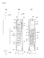
- a first embodiment is one in which, as shown in Figs. 1 and 2 , a contactor 10 is formed of a bellows body 20, a fixed portion 30 connected to one end 21 of the bellows body 20, and a movable portion 40 connected to the other end 22 of the bellows body 20.
- the contactor 10 is housed inside a housing 50.
- the bellows body 20 is formed of linear-shaped intermediate portions 23 and arc portions 24 each connecting adjacent intermediate portions 23, 23.
- the bellows body 20 may have a cross section with an aspect ratio being not smaller than 1.5, preferably not smaller than 2, and may be formed by pressing or by electroforming. It is to be noted that the aspect ratio here refers to a ratio of a thickness and a height on the cross section of the bellows body 20.
- the one end 21 of the bellows body 20 is connected onto a shaft center of the fixed portion 30 out of the upper end thereof, and a terminal portion 31 is extended at the lower end of the fixed portion 30 along the shaft center. Further, a locking claw portion 32 is projectingly provided on each side surface of the fixed portion 30.
- the movable portion 40 has the front surface in a substantially T-shape.
- the other end 22 of the bellows body 20 is connected onto the shaft center out of the lower end of a large width portion 41 of the movable portion 40, while a movable touch piece 42 is extended from the one side edge thereof along the bellows body 20. Then, the free end of the movable touch piece 42 is made a movable contact point 43.
- the housing 50 has a rectangular-parallelepiped shape having a slit 51 where the contactor 10 can be housed, and the upper end of the housing 50 has an operation hole 52, while the lower end thereof has a press-fitting hole 53.
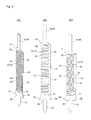
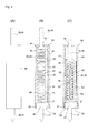
- a second embodiment is one similar to the foregoing first embodiment, where a contactor 10 is formed of a bellows body 20, a fixed portion 30 connected to one end 21 of the bellows body 20, and a movable portion 40 connected to the other end 22 of the bellows body 20.
- the contactor 10 is housed inside a housing 50.
- the bellows body 20 is formed of linear-shaped intermediate portions 23 and arc portions 24 each connecting adjacent intermediate portions 23, 23.
- the one end 21 of the bellows body 20 is connected onto a shaft center of the fixed portion 30 out of the upper end thereof, and a terminal portion 31 is extended at the lower end of the fixed portion 30 along the shaft center. Further, a locking claw portion 32 is projectingly provided on each side surface of the fixed portion 30, and a fixed touch piece 33 is extended from one side edge of the upper side of the fixed portion 30 along the bellows body 20.
- the movable portion 40 has the front surface in a substantially T-shape.
- the other end 22 of the bellows body 20 is connected onto the shaft center out of the lower end of a large width portion 41 of the movable portion 40, while a movable touch piece 42 is extended from the one-side edge thereof in parallel along the bellows body 20. Then, the free end of the movable touch piece 42 is made a movable contact point 43.
- the housing 50 has a rectangular-parallelepiped shape having a slit 51 where the contactor 10 can be housed, and the upper end of the housing 50 has an operation hole 52, while the lower end thereof has a press-fitting hole 53.
- the movable touch piece 42 may be arranged on each side of the bellows body 20, or the fixed touch piece 33 may be provided on each side according to the need.
- the bellows body 20 is formed of the linear-shaped intermediate portion 23 and the arc portion 24 connecting the adjacent intermediate portions 23, 23, it may be formed of curve-shaped intermediate portions and arc portions each connecting the adjacent intermediate portions.
- the contactor according to the present invention is not only usable as an integrated circuit inspection probe, but also usable as a switch or a contact terminal of a battery. Especially when it is used as the integrated circuit inspection probe, since the above contactor can be formed with a small thickness, it is possible to arrange a large number of contactors at narrow pitches, while obtaining an integrated circuit inspection probe with a small number of components.
- the housing is not restricted to an integrally molded one, but may be one dividable into two parts.
Landscapes
- Physics & Mathematics (AREA)
- General Physics & Mathematics (AREA)
- Measuring Leads Or Probes (AREA)
- Connecting Device With Holders (AREA)
- Push-Button Switches (AREA)
Abstract
Description
- The present invention relates to a contactor, and for example, relates to a contactor used for an integrated circuit inspection probe.
- As a contactor used for an integrated circuit inspection probe, there has hitherto been a contactor of an electronic terminal receptacle, which holds contact between an electrode terminal of an electronic component and an electrode portion of a receptacle body by depressing the electronic component to the receptacle body, and connects the electrode portion of the receptacle body to an electrode terminal of a connected electronic component. The electrode portion of the receptacle main body is formed by performing punching on an elastic plate material with a predetermined thickness, and has at both ends a pair of contacts respectively connected with the electrode terminal of the electronic component and the electrode terminal of the connected electronic component, while having a meandering portion successively installed in parallel and provided between the pair of contacts to connect the pair of contacts (cf. Patent Document 1).
- Patent Document 1: Japanese Unexamined Patent Publication No.
2002-134202 - However, in the contactor of the foregoing electronic terminal receptacle, the number of folding times of the meandering portion is small and a desired shrinkage amount (displacement amount) is thus difficult to ensure, which leads to lowered usability. For this reason, in order to ensure the desired shrinkage amount (displacement amount), there can be considered a long contactor of the electronic terminal receptacle where the number of folding times has been increased. However, when the meandering portion of the long contactor becomes narrow, electric resistance increases to make it difficult for a current to flow and there are thus limits on lengthening of the contactor, which is problematic.
- In view of the foregoing problems, an object of present invention is to provide a contactor having desired conductivity while ensuring a predetermined displacement amount.
- In order to solve the above problem, a contactor according to the present invention has: a bellows body; a fixed portion, connected to one end of the bellows body; and a movable portion, connected to the other end of the bellows body and having a movable touch piece that extends from at least one side edge along the bellows body. The contactor has a configuration where the movable portion is depressed to compress the bellows body and bring a movable contact point, located at a free end of the movable touch piece, into contact with the fixed portion.
- According to the present invention, even when the bellows body is made long for the purpose of ensuring a desired displacement amount, a short-circuit occurs by contact between the movable touch piece of the movable portion and the fixed portion, thus making it possible to reduce contact resistance, so as to obtain a contactor with small contact resistance.
- As an embodiment according to the present invention, a fixed touch piece configured to contact to and separate from the movable contact point of the movable touch piece may extend from at least one side edge of the fixed portion along the bellows body.
- According to the present embodiment, even when the bellows body is made long for the purpose of ensuring a desired displacement amount, a short-circuit occurs by contact between the movable touch piece of the movable portion and the fixed touch piece of the fixed portion, thus making it possible to reduce contact resistance, so as to obtain a contactor with small contact resistance.
- As another embodiment according to the present invention, a configuration may be formed where the movable contact point of the movable touch piece extending from each side edge of the movable portion is arranged contactably to and separably from the fixed touch piece extending from each side edge of the fixed portion.
- According to the present embodiment, the pair of movable touch pieces is arranged contactably to and separably from the pair of fixed touch pieces, thus making it possible to obtain a contactor with high contact reliability.
- As another embodiment of the present invention, the bellows body may have a shape made up of linear-shaped intermediate portions and arc portions each configured to connect the adjacent intermediate portions.
- According to the present embodiment, it is possible to obtain a contactor easy to design.
- As another embodiment of the present invention, the bellows body may have a shape made up of curve-shaped intermediate portions and arc portions each configured to connect the adjacent intermediate portions.
- According to the present embodiment, there is an advantage of increasing the design flexibility.
- As a different embodiment of the present invention, a position of contact between the bellows body and the fixed portion may be arranged on a shaft center of the fixed portion.
- According to the present embodiment, when the position of contact between the bellows body and the fixed portion is arranged on the shaft center of the fixed portion, there can be obtained a contactor being operable by small force of operation and having a long life.
- As a different embodiment of the present invention, a position of contact between the bellows body and the movable portion may be arranged on a shaft center of the movable portion.
- According to the present embodiment, when the position of contact between the bellows body and the movable portion is arranged on the shaft center of the movable portion, there is an affect of being able to obtain a contactor being operable by small force of operation and having a long life.
-
-
Fig. 1A is a perspective view showing a first embodiment of a contactor according to the present invention, andFigs. 1B and 1C are front views respectively showing the contactor before and after an operation. -
Fig. 2A is a front view of a state where the contactor shown inFig. 1 has been housed inside a housing, andFigs. 2B and 2C are front sectional views respectively showing the contactors before and after the operation. -
Fig. 3A is a perspective view showing a second embodiment of a contactor according to the present invention, andFigs. 3B and 3C are front views respectively showing the contactor before and after the operation. -
Fig. 4A is a front view of a state where the contactor shown inFig. 3 has been housed inside a housing, andFigs. 4B and 4C are front sectional views respectively showing the contactors before and after the operation. - Embodiments of a contactor according to the present invention will be described in accordance with the accompanying drawing of
Figs. 1 to 4 . - A first embodiment is one in which, as shown in
Figs. 1 and2 , a contactor 10 is formed of a bellows body 20, a fixedportion 30 connected to oneend 21 of the bellows body 20, and a movable portion 40 connected to theother end 22 of the bellows body 20. The contactor 10 is housed inside ahousing 50. - The bellows body 20 is formed of linear-shaped
intermediate portions 23 andarc portions 24 each connecting adjacentintermediate portions - The one
end 21 of the bellows body 20 is connected onto a shaft center of the fixedportion 30 out of the upper end thereof, and aterminal portion 31 is extended at the lower end of the fixedportion 30 along the shaft center. Further, alocking claw portion 32 is projectingly provided on each side surface of the fixedportion 30. - The movable portion 40 has the front surface in a substantially T-shape. The
other end 22 of the bellows body 20 is connected onto the shaft center out of the lower end of alarge width portion 41 of the movable portion 40, while amovable touch piece 42 is extended from the one side edge thereof along the bellows body 20. Then, the free end of themovable touch piece 42 is made amovable contact point 43. - As shown in
Fig. 2 , thehousing 50 has a rectangular-parallelepiped shape having aslit 51 where the contactor 10 can be housed, and the upper end of thehousing 50 has anoperation hole 52, while the lower end thereof has a press-fitting hole 53. - Then, as shown in
Fig. 2 , when the movable portion 40 is pressed down, thelarge width portion 41 descends by the bellows body 20 being compressed, and themovable contact point 43 of themovable touch piece 42 comes into contact with the side surface of the fixedportion 30, to cause a short circuit. Hence the contact resistance decreases, to allow a current to flow. - As shown in
Figs. 3 and4 , a second embodiment is one similar to the foregoing first embodiment, where a contactor 10 is formed of a bellows body 20, a fixedportion 30 connected to oneend 21 of the bellows body 20, and a movable portion 40 connected to theother end 22 of the bellows body 20. The contactor 10 is housed inside ahousing 50. - The bellows body 20 is formed of linear-shaped
intermediate portions 23 andarc portions 24 each connecting adjacentintermediate portions - The one
end 21 of the bellows body 20 is connected onto a shaft center of the fixedportion 30 out of the upper end thereof, and aterminal portion 31 is extended at the lower end of the fixedportion 30 along the shaft center. Further, alocking claw portion 32 is projectingly provided on each side surface of the fixedportion 30, and afixed touch piece 33 is extended from one side edge of the upper side of the fixedportion 30 along the bellows body 20. - The movable portion 40 has the front surface in a substantially T-shape. The
other end 22 of the bellows body 20 is connected onto the shaft center out of the lower end of alarge width portion 41 of the movable portion 40, while amovable touch piece 42 is extended from the one-side edge thereof in parallel along the bellows body 20. Then, the free end of themovable touch piece 42 is made amovable contact point 43. - As shown in
Fig. 4 , thehousing 50 has a rectangular-parallelepiped shape having aslit 51 where the contactor 10 can be housed, and the upper end of thehousing 50 has anoperation hole 52, while the lower end thereof has a press-fittinghole 53. - When the movable portion 40 is pressed down, the bellows body 20 is compressed, the
large width portion 41 descends and themovable contact point 43 of themovable touch piece 42 comes into contact with the outer side surface of the fixedtouch piece 33, to cause a short circuit, whereby the contact resistance decreases and a current flows. - According to the present embodiment, there is an advantage of adjusting the timing for contact switching by adjusting the lengths of the
movable touch piece 42 and the fixedtouch piece 33. - Although the case has been described in the foregoing embodiment where the
movable touch piece 42 is provided on one side of the bellows body 20, themovable touch piece 42 may be arranged on each side of the bellows body 20, or the fixedtouch piece 33 may be provided on each side according to the need. - Further, although the case has been described in the foregoing embodiment where the bellows body 20 is formed of the linear-shaped
intermediate portion 23 and thearc portion 24 connecting the adjacentintermediate portions - The contactor according to the present invention is not only usable as an integrated circuit inspection probe, but also usable as a switch or a contact terminal of a battery. Especially when it is used as the integrated circuit inspection probe, since the above contactor can be formed with a small thickness, it is possible to arrange a large number of contactors at narrow pitches, while obtaining an integrated circuit inspection probe with a small number of components.
- Needless to say, the housing is not restricted to an integrally molded one, but may be one dividable into two parts.
-
- 10
- contactor
- 20
- bellows body
- 21
- one end
- 22
- other end
- 23
- intermediate portion
- 24
- arc portion
- 30
- fixed portion
- 31
- terminal portion
- 32
- locking claw portion
- 33
- fixed touch piece
- 40
- movable portion
- 41
- large width portion
- 42
- movable touch piece
- 43
- movable contact point
- 50
- housing
- 51
- slit
- 52
- operation hole
- 53
- press-fitting hole
Claims (7)
- A contactor according to the present invention comprises:a bellows body;a fixed portion, connected to one end of the bellows body; anda movable portion, connected to the other end of the bellows body and comprising a movable touch piece that extends from at least one side edge along the bellows body,wherein the movable portion is depressed to compress the bellows body and bring a movable contact point, located at a free end of the movable touch piece, into contact with the fixed portion.
- The contactor according to claim 1, wherein a fixed touch piece configured to contact to and separate from the movable contact point of the movable touch piece extends from at least one side edge of the fixed portion along the bellows body.
- The contactor according to claim 2, wherein the movable contact point of the movable touch piece extending from both side edges of the movable portion is arranged contactably to and separably from the fixed touch piece extending from each side edge of the fixed portion.
- The contactor according to any one of claims 1 to 3, wherein the bellows body is made up of linear-shaped intermediate portions and arc portions each configured to connect the adjacent intermediate portions.
- The contactor according to any one of claims 1 to 3, wherein the bellows body is made up of curve-shaped intermediate portions and arc portions each configured to connect the adjacent intermediate portions.
- The contactor according to any one of claims 1 to 5, wherein a position of contact between the bellows body and the fixed portion is arranged on a shaft center of the fixed portion.
- The contactor according to any one of claims 1 to 5, wherein a position of contact between the bellows body and the movable portion is arranged on a shaft center of the movable portion.
Applications Claiming Priority (2)
| Application Number | Priority Date | Filing Date | Title |
|---|---|---|---|
| JP2011227170A JP5699899B2 (en) | 2011-10-14 | 2011-10-14 | Contact |
| PCT/JP2012/056654 WO2013054554A1 (en) | 2011-10-14 | 2012-03-15 | Contactor |
Publications (3)
| Publication Number | Publication Date |
|---|---|
| EP2747210A1 true EP2747210A1 (en) | 2014-06-25 |
| EP2747210A4 EP2747210A4 (en) | 2015-01-14 |
| EP2747210B1 EP2747210B1 (en) | 2017-08-16 |
Family
ID=48081618
Family Applications (1)
| Application Number | Title | Priority Date | Filing Date |
|---|---|---|---|
| EP12839653.8A Active EP2747210B1 (en) | 2011-10-14 | 2012-03-15 | Contactor |
Country Status (6)
| Country | Link |
|---|---|
| US (1) | US9322846B2 (en) |
| EP (1) | EP2747210B1 (en) |
| JP (1) | JP5699899B2 (en) |
| KR (1) | KR101545105B1 (en) |
| CN (1) | CN103765688B (en) |
| WO (1) | WO2013054554A1 (en) |
Families Citing this family (28)
| Publication number | Priority date | Publication date | Assignee | Title |
|---|---|---|---|---|
| JP5842528B2 (en) * | 2011-10-14 | 2016-01-13 | オムロン株式会社 | Contact |
| JP5708430B2 (en) * | 2011-10-14 | 2015-04-30 | オムロン株式会社 | Contact |
| JP6268896B2 (en) * | 2013-10-10 | 2018-01-31 | オムロン株式会社 | Contact |
| CN105529552B (en) * | 2014-09-30 | 2017-11-10 | 上海莫仕连接器有限公司 | Electric connector and terminal thereof |
| JP1529604S (en) * | 2014-12-04 | 2015-07-27 | ||
| JP1529603S (en) * | 2014-12-04 | 2015-07-27 | ||
| JP1529602S (en) * | 2014-12-04 | 2015-07-27 | ||
| TWD177827S (en) * | 2014-12-15 | 2016-08-21 | 歐姆龍股份有限公司 | A part of probe pin for ic socket |
| JP1529608S (en) * | 2014-12-15 | 2015-07-27 | ||
| JP1529606S (en) * | 2014-12-15 | 2015-07-27 | ||
| JP1529607S (en) * | 2014-12-15 | 2015-07-27 | ||
| JP1529605S (en) * | 2014-12-15 | 2015-07-27 | ||
| JP1529609S (en) * | 2014-12-15 | 2015-07-27 | ||
| JP1529612S (en) * | 2014-12-19 | 2015-07-27 | ||
| JP1529613S (en) * | 2014-12-19 | 2015-07-27 | ||
| USD775984S1 (en) * | 2015-03-04 | 2017-01-10 | Omron Corporation | Probe pin |
| TWI555279B (en) * | 2015-06-02 | 2016-10-21 | 技鼎股份有限公司 | Electrical contact |
| JP1554474S (en) * | 2015-09-15 | 2016-07-25 | ||
| JP1554473S (en) * | 2015-09-15 | 2016-07-25 | ||
| JP1567318S (en) * | 2016-02-15 | 2017-01-23 | ||
| JP1567321S (en) * | 2016-02-15 | 2017-01-23 | ||
| JP1567319S (en) * | 2016-02-15 | 2017-01-23 | ||
| JP6669533B2 (en) | 2016-02-29 | 2020-03-18 | 株式会社エンプラス | Contact pins and sockets for electrical components |
| JP6642359B2 (en) | 2016-09-21 | 2020-02-05 | オムロン株式会社 | Probe pin and inspection unit |
| JP7620385B2 (en) * | 2019-04-25 | 2025-01-23 | オムロン株式会社 | Probe pins, inspection jigs and inspection units |
| JP7393980B2 (en) * | 2020-03-05 | 2023-12-07 | ヒロセ電機株式会社 | Electrical connectors for circuit boards and electrical connectors with circuit boards |
| TWI917587B (en) * | 2021-03-31 | 2026-03-11 | 南韓商普因特工程有限公司 | The electro-conductive contact pin |
| KR20260037983A (en) | 2024-09-11 | 2026-03-18 | (주)포인트엔지니어링 | The Electro-conductive Contact Pin |
Family Cites Families (16)
| Publication number | Priority date | Publication date | Assignee | Title |
|---|---|---|---|---|
| US4161346A (en) | 1978-08-22 | 1979-07-17 | Amp Incorporated | Connecting element for surface to surface connectors |
| JP2912882B2 (en) * | 1996-10-23 | 1999-06-28 | 山一電機株式会社 | Double-sided contact type connector |
| JP3773396B2 (en) * | 2000-06-01 | 2006-05-10 | 住友電気工業株式会社 | Contact probe and manufacturing method thereof |
| JP3520468B2 (en) | 2000-06-21 | 2004-04-19 | 日本航空電子工業株式会社 | connector |
| JP2002134202A (en) | 2000-10-27 | 2002-05-10 | Otax Co Ltd | Socket for electronic components |
| JP2002164135A (en) | 2000-11-26 | 2002-06-07 | Isao Kimoto | socket |
| JP2003307525A (en) * | 2002-04-16 | 2003-10-31 | Sumitomo Electric Ind Ltd | Contact probe |
| US20060238209A1 (en) * | 2002-05-07 | 2006-10-26 | Microfabrica Inc. | Vertical microprobes for contacting electronic components and method for making such probes |
| JP2004138391A (en) | 2002-10-15 | 2004-05-13 | Renesas Technology Corp | Method for manufacturing semiconductor device |
| CN2800519Y (en) | 2005-04-28 | 2006-07-26 | 富士康(昆山)电脑接插件有限公司 | Electric connector |
| CN2800520Y (en) * | 2005-04-28 | 2006-07-26 | 富士康(昆山)电脑接插件有限公司 | Electric connector |
| JP2008047417A (en) | 2006-08-16 | 2008-02-28 | Bairong Electron Co Ltd | Terminal for electric connector, and electric connector equipped with the same |
| WO2009058858A1 (en) | 2007-10-29 | 2009-05-07 | Ardent Concepts, Inc. | Compliant electrical contact and assembly |
| JP5103566B2 (en) * | 2007-11-26 | 2012-12-19 | 株式会社コーヨーテクノス | Electrical contact and inspection jig having the same |
| JP4964754B2 (en) * | 2007-12-17 | 2012-07-04 | 富士通コンポーネント株式会社 | Contact material |
| JP5493896B2 (en) | 2010-01-15 | 2014-05-14 | オムロン株式会社 | Electrical connector, electronic device and conductive contact method. |
-
2011
- 2011-10-14 JP JP2011227170A patent/JP5699899B2/en active Active
-
2012
- 2012-03-15 CN CN201280040999.1A patent/CN103765688B/en active Active
- 2012-03-15 EP EP12839653.8A patent/EP2747210B1/en active Active
- 2012-03-15 US US14/343,114 patent/US9322846B2/en active Active
- 2012-03-15 KR KR1020147004557A patent/KR101545105B1/en active Active
- 2012-03-15 WO PCT/JP2012/056654 patent/WO2013054554A1/en not_active Ceased
Also Published As
| Publication number | Publication date |
|---|---|
| CN103765688A (en) | 2014-04-30 |
| KR20140043818A (en) | 2014-04-10 |
| EP2747210B1 (en) | 2017-08-16 |
| JP2013089373A (en) | 2013-05-13 |
| KR101545105B1 (en) | 2015-08-17 |
| US20140218062A1 (en) | 2014-08-07 |
| JP5699899B2 (en) | 2015-04-15 |
| CN103765688B (en) | 2016-04-27 |
| US9322846B2 (en) | 2016-04-26 |
| EP2747210A4 (en) | 2015-01-14 |
| WO2013054554A1 (en) | 2013-04-18 |
Similar Documents
| Publication | Publication Date | Title |
|---|---|---|
| EP2747210B1 (en) | Contactor | |
| EP2747209B1 (en) | Contactor | |
| EP2747212B1 (en) | Contactor | |
| EP2747211B1 (en) | Contactor and probe using the same | |
| EP2175531A1 (en) | Coaxial connector | |
| EP4417980A1 (en) | Contact pin and spring contact including the same | |
| JP5587449B1 (en) | Coaxial connector with switch | |
| JP2015076325A (en) | Contactor | |
| JP2016126834A (en) | Lever switch | |
| CN201518305U (en) | Movable contact spring for current protector |
Legal Events
| Date | Code | Title | Description |
|---|---|---|---|
| PUAI | Public reference made under article 153(3) epc to a published international application that has entered the european phase |
Free format text: ORIGINAL CODE: 0009012 |
|
| 17P | Request for examination filed |
Effective date: 20140321 |
|
| AK | Designated contracting states |
Kind code of ref document: A1 Designated state(s): AL AT BE BG CH CY CZ DE DK EE ES FI FR GB GR HR HU IE IS IT LI LT LU LV MC MK MT NL NO PL PT RO RS SE SI SK SM TR |
|
| A4 | Supplementary search report drawn up and despatched |
Effective date: 20141212 |
|
| RIC1 | Information provided on ipc code assigned before grant |
Ipc: H01R 33/76 20060101ALI20141208BHEP Ipc: H01R 13/24 20060101AFI20141208BHEP Ipc: G01R 1/067 20060101ALI20141208BHEP |
|
| DAX | Request for extension of the european patent (deleted) | ||
| 17Q | First examination report despatched |
Effective date: 20160804 |
|
| STAA | Information on the status of an ep patent application or granted ep patent |
Free format text: STATUS: EXAMINATION IS IN PROGRESS |
|
| GRAP | Despatch of communication of intention to grant a patent |
Free format text: ORIGINAL CODE: EPIDOSNIGR1 |
|
| STAA | Information on the status of an ep patent application or granted ep patent |
Free format text: STATUS: GRANT OF PATENT IS INTENDED |
|
| INTG | Intention to grant announced |
Effective date: 20170220 |
|
| GRAS | Grant fee paid |
Free format text: ORIGINAL CODE: EPIDOSNIGR3 |
|
| GRAA | (expected) grant |
Free format text: ORIGINAL CODE: 0009210 |
|
| STAA | Information on the status of an ep patent application or granted ep patent |
Free format text: STATUS: THE PATENT HAS BEEN GRANTED |
|
| AK | Designated contracting states |
Kind code of ref document: B1 Designated state(s): AL AT BE BG CH CY CZ DE DK EE ES FI FR GB GR HR HU IE IS IT LI LT LU LV MC MK MT NL NO PL PT RO RS SE SI SK SM TR |
|
| REG | Reference to a national code |
Ref country code: GB Ref legal event code: FG4D |
|
| REG | Reference to a national code |
Ref country code: CH Ref legal event code: EP |
|
| REG | Reference to a national code |
Ref country code: IE Ref legal event code: FG4D |
|
| REG | Reference to a national code |
Ref country code: AT Ref legal event code: REF Ref document number: 919928 Country of ref document: AT Kind code of ref document: T Effective date: 20170915 |
|
| REG | Reference to a national code |
Ref country code: DE Ref legal event code: R096 Ref document number: 602012036112 Country of ref document: DE |
|
| REG | Reference to a national code |
Ref country code: NL Ref legal event code: MP Effective date: 20170816 |
|
| REG | Reference to a national code |
Ref country code: LT Ref legal event code: MG4D |
|
| REG | Reference to a national code |
Ref country code: AT Ref legal event code: MK05 Ref document number: 919928 Country of ref document: AT Kind code of ref document: T Effective date: 20170816 |
|
| PG25 | Lapsed in a contracting state [announced via postgrant information from national office to epo] |
Ref country code: LT Free format text: LAPSE BECAUSE OF FAILURE TO SUBMIT A TRANSLATION OF THE DESCRIPTION OR TO PAY THE FEE WITHIN THE PRESCRIBED TIME-LIMIT Effective date: 20170816 Ref country code: AT Free format text: LAPSE BECAUSE OF FAILURE TO SUBMIT A TRANSLATION OF THE DESCRIPTION OR TO PAY THE FEE WITHIN THE PRESCRIBED TIME-LIMIT Effective date: 20170816 Ref country code: NL Free format text: LAPSE BECAUSE OF FAILURE TO SUBMIT A TRANSLATION OF THE DESCRIPTION OR TO PAY THE FEE WITHIN THE PRESCRIBED TIME-LIMIT Effective date: 20170816 Ref country code: NO Free format text: LAPSE BECAUSE OF FAILURE TO SUBMIT A TRANSLATION OF THE DESCRIPTION OR TO PAY THE FEE WITHIN THE PRESCRIBED TIME-LIMIT Effective date: 20171116 Ref country code: FI Free format text: LAPSE BECAUSE OF FAILURE TO SUBMIT A TRANSLATION OF THE DESCRIPTION OR TO PAY THE FEE WITHIN THE PRESCRIBED TIME-LIMIT Effective date: 20170816 Ref country code: SE Free format text: LAPSE BECAUSE OF FAILURE TO SUBMIT A TRANSLATION OF THE DESCRIPTION OR TO PAY THE FEE WITHIN THE PRESCRIBED TIME-LIMIT Effective date: 20170816 |
|
| PG25 | Lapsed in a contracting state [announced via postgrant information from national office to epo] |
Ref country code: BG Free format text: LAPSE BECAUSE OF FAILURE TO SUBMIT A TRANSLATION OF THE DESCRIPTION OR TO PAY THE FEE WITHIN THE PRESCRIBED TIME-LIMIT Effective date: 20171116 Ref country code: GR Free format text: LAPSE BECAUSE OF FAILURE TO SUBMIT A TRANSLATION OF THE DESCRIPTION OR TO PAY THE FEE WITHIN THE PRESCRIBED TIME-LIMIT Effective date: 20171117 Ref country code: ES Free format text: LAPSE BECAUSE OF FAILURE TO SUBMIT A TRANSLATION OF THE DESCRIPTION OR TO PAY THE FEE WITHIN THE PRESCRIBED TIME-LIMIT Effective date: 20170816 Ref country code: IS Free format text: LAPSE BECAUSE OF FAILURE TO SUBMIT A TRANSLATION OF THE DESCRIPTION OR TO PAY THE FEE WITHIN THE PRESCRIBED TIME-LIMIT Effective date: 20171216 Ref country code: RS Free format text: LAPSE BECAUSE OF FAILURE TO SUBMIT A TRANSLATION OF THE DESCRIPTION OR TO PAY THE FEE WITHIN THE PRESCRIBED TIME-LIMIT Effective date: 20170816 Ref country code: PL Free format text: LAPSE BECAUSE OF FAILURE TO SUBMIT A TRANSLATION OF THE DESCRIPTION OR TO PAY THE FEE WITHIN THE PRESCRIBED TIME-LIMIT Effective date: 20170816 Ref country code: LV Free format text: LAPSE BECAUSE OF FAILURE TO SUBMIT A TRANSLATION OF THE DESCRIPTION OR TO PAY THE FEE WITHIN THE PRESCRIBED TIME-LIMIT Effective date: 20170816 |
|
| PG25 | Lapsed in a contracting state [announced via postgrant information from national office to epo] |
Ref country code: RO Free format text: LAPSE BECAUSE OF FAILURE TO SUBMIT A TRANSLATION OF THE DESCRIPTION OR TO PAY THE FEE WITHIN THE PRESCRIBED TIME-LIMIT Effective date: 20170816 Ref country code: CZ Free format text: LAPSE BECAUSE OF FAILURE TO SUBMIT A TRANSLATION OF THE DESCRIPTION OR TO PAY THE FEE WITHIN THE PRESCRIBED TIME-LIMIT Effective date: 20170816 Ref country code: DK Free format text: LAPSE BECAUSE OF FAILURE TO SUBMIT A TRANSLATION OF THE DESCRIPTION OR TO PAY THE FEE WITHIN THE PRESCRIBED TIME-LIMIT Effective date: 20170816 |
|
| REG | Reference to a national code |
Ref country code: DE Ref legal event code: R097 Ref document number: 602012036112 Country of ref document: DE |
|
| PG25 | Lapsed in a contracting state [announced via postgrant information from national office to epo] |
Ref country code: SM Free format text: LAPSE BECAUSE OF FAILURE TO SUBMIT A TRANSLATION OF THE DESCRIPTION OR TO PAY THE FEE WITHIN THE PRESCRIBED TIME-LIMIT Effective date: 20170816 Ref country code: EE Free format text: LAPSE BECAUSE OF FAILURE TO SUBMIT A TRANSLATION OF THE DESCRIPTION OR TO PAY THE FEE WITHIN THE PRESCRIBED TIME-LIMIT Effective date: 20170816 Ref country code: IT Free format text: LAPSE BECAUSE OF FAILURE TO SUBMIT A TRANSLATION OF THE DESCRIPTION OR TO PAY THE FEE WITHIN THE PRESCRIBED TIME-LIMIT Effective date: 20170816 Ref country code: SK Free format text: LAPSE BECAUSE OF FAILURE TO SUBMIT A TRANSLATION OF THE DESCRIPTION OR TO PAY THE FEE WITHIN THE PRESCRIBED TIME-LIMIT Effective date: 20170816 |
|
| PLBE | No opposition filed within time limit |
Free format text: ORIGINAL CODE: 0009261 |
|
| STAA | Information on the status of an ep patent application or granted ep patent |
Free format text: STATUS: NO OPPOSITION FILED WITHIN TIME LIMIT |
|
| 26N | No opposition filed |
Effective date: 20180517 |
|
| PG25 | Lapsed in a contracting state [announced via postgrant information from national office to epo] |
Ref country code: SI Free format text: LAPSE BECAUSE OF FAILURE TO SUBMIT A TRANSLATION OF THE DESCRIPTION OR TO PAY THE FEE WITHIN THE PRESCRIBED TIME-LIMIT Effective date: 20170816 |
|
| REG | Reference to a national code |
Ref country code: CH Ref legal event code: PL |
|
| GBPC | Gb: european patent ceased through non-payment of renewal fee |
Effective date: 20180315 |
|
| PG25 | Lapsed in a contracting state [announced via postgrant information from national office to epo] |
Ref country code: MC Free format text: LAPSE BECAUSE OF FAILURE TO SUBMIT A TRANSLATION OF THE DESCRIPTION OR TO PAY THE FEE WITHIN THE PRESCRIBED TIME-LIMIT Effective date: 20170816 |
|
| REG | Reference to a national code |
Ref country code: BE Ref legal event code: MM Effective date: 20180331 |
|
| REG | Reference to a national code |
Ref country code: IE Ref legal event code: MM4A |
|
| PG25 | Lapsed in a contracting state [announced via postgrant information from national office to epo] |
Ref country code: LU Free format text: LAPSE BECAUSE OF NON-PAYMENT OF DUE FEES Effective date: 20180315 |
|
| PG25 | Lapsed in a contracting state [announced via postgrant information from national office to epo] |
Ref country code: IE Free format text: LAPSE BECAUSE OF NON-PAYMENT OF DUE FEES Effective date: 20180315 |
|
| PG25 | Lapsed in a contracting state [announced via postgrant information from national office to epo] |
Ref country code: LI Free format text: LAPSE BECAUSE OF NON-PAYMENT OF DUE FEES Effective date: 20180331 Ref country code: CH Free format text: LAPSE BECAUSE OF NON-PAYMENT OF DUE FEES Effective date: 20180331 Ref country code: BE Free format text: LAPSE BECAUSE OF NON-PAYMENT OF DUE FEES Effective date: 20180331 Ref country code: GB Free format text: LAPSE BECAUSE OF NON-PAYMENT OF DUE FEES Effective date: 20180315 |
|
| PG25 | Lapsed in a contracting state [announced via postgrant information from national office to epo] |
Ref country code: FR Free format text: LAPSE BECAUSE OF NON-PAYMENT OF DUE FEES Effective date: 20180331 |
|
| PG25 | Lapsed in a contracting state [announced via postgrant information from national office to epo] |
Ref country code: MT Free format text: LAPSE BECAUSE OF NON-PAYMENT OF DUE FEES Effective date: 20180315 |
|
| PG25 | Lapsed in a contracting state [announced via postgrant information from national office to epo] |
Ref country code: TR Free format text: LAPSE BECAUSE OF FAILURE TO SUBMIT A TRANSLATION OF THE DESCRIPTION OR TO PAY THE FEE WITHIN THE PRESCRIBED TIME-LIMIT Effective date: 20170816 |
|
| PG25 | Lapsed in a contracting state [announced via postgrant information from national office to epo] |
Ref country code: PT Free format text: LAPSE BECAUSE OF FAILURE TO SUBMIT A TRANSLATION OF THE DESCRIPTION OR TO PAY THE FEE WITHIN THE PRESCRIBED TIME-LIMIT Effective date: 20170816 Ref country code: HU Free format text: LAPSE BECAUSE OF FAILURE TO SUBMIT A TRANSLATION OF THE DESCRIPTION OR TO PAY THE FEE WITHIN THE PRESCRIBED TIME-LIMIT; INVALID AB INITIO Effective date: 20120315 |
|
| PG25 | Lapsed in a contracting state [announced via postgrant information from national office to epo] |
Ref country code: MK Free format text: LAPSE BECAUSE OF NON-PAYMENT OF DUE FEES Effective date: 20170816 Ref country code: HR Free format text: LAPSE BECAUSE OF FAILURE TO SUBMIT A TRANSLATION OF THE DESCRIPTION OR TO PAY THE FEE WITHIN THE PRESCRIBED TIME-LIMIT Effective date: 20170816 Ref country code: CY Free format text: LAPSE BECAUSE OF FAILURE TO SUBMIT A TRANSLATION OF THE DESCRIPTION OR TO PAY THE FEE WITHIN THE PRESCRIBED TIME-LIMIT Effective date: 20170816 |
|
| PG25 | Lapsed in a contracting state [announced via postgrant information from national office to epo] |
Ref country code: AL Free format text: LAPSE BECAUSE OF FAILURE TO SUBMIT A TRANSLATION OF THE DESCRIPTION OR TO PAY THE FEE WITHIN THE PRESCRIBED TIME-LIMIT Effective date: 20170816 |
|
| PGFP | Annual fee paid to national office [announced via postgrant information from national office to epo] |
Ref country code: DE Payment date: 20260320 Year of fee payment: 15 |