EP2746865B1 - Timepiece barrel - Google Patents
Timepiece barrel Download PDFInfo
- Publication number
- EP2746865B1 EP2746865B1 EP12197741.7A EP12197741A EP2746865B1 EP 2746865 B1 EP2746865 B1 EP 2746865B1 EP 12197741 A EP12197741 A EP 12197741A EP 2746865 B1 EP2746865 B1 EP 2746865B1
- Authority
- EP
- European Patent Office
- Prior art keywords
- bore
- barrel
- plate
- drum
- spring
- Prior art date
- Legal status (The legal status is an assumption and is not a legal conclusion. Google has not performed a legal analysis and makes no representation as to the accuracy of the status listed.)
- Active
Links
- XEEYBQQBJWHFJM-UHFFFAOYSA-N Iron Chemical compound [Fe] XEEYBQQBJWHFJM-UHFFFAOYSA-N 0.000 claims description 6
- PXHVJJICTQNCMI-UHFFFAOYSA-N Nickel Chemical compound [Ni] PXHVJJICTQNCMI-UHFFFAOYSA-N 0.000 claims description 6
- 238000003466 welding Methods 0.000 claims description 4
- VYZAMTAEIAYCRO-UHFFFAOYSA-N Chromium Chemical compound [Cr] VYZAMTAEIAYCRO-UHFFFAOYSA-N 0.000 claims description 3
- ZOKXTWBITQBERF-UHFFFAOYSA-N Molybdenum Chemical compound [Mo] ZOKXTWBITQBERF-UHFFFAOYSA-N 0.000 claims description 3
- RTAQQCXQSZGOHL-UHFFFAOYSA-N Titanium Chemical compound [Ti] RTAQQCXQSZGOHL-UHFFFAOYSA-N 0.000 claims description 3
- 239000000956 alloy Substances 0.000 claims description 3
- 229910045601 alloy Inorganic materials 0.000 claims description 3
- 229910052790 beryllium Inorganic materials 0.000 claims description 3
- ATBAMAFKBVZNFJ-UHFFFAOYSA-N beryllium atom Chemical compound [Be] ATBAMAFKBVZNFJ-UHFFFAOYSA-N 0.000 claims description 3
- 229910052804 chromium Inorganic materials 0.000 claims description 3
- 239000011651 chromium Substances 0.000 claims description 3
- SZMZREIADCOWQA-UHFFFAOYSA-N chromium cobalt nickel Chemical compound [Cr].[Co].[Ni] SZMZREIADCOWQA-UHFFFAOYSA-N 0.000 claims description 3
- 239000010941 cobalt Substances 0.000 claims description 3
- 229910017052 cobalt Inorganic materials 0.000 claims description 3
- GUTLYIVDDKVIGB-UHFFFAOYSA-N cobalt atom Chemical compound [Co] GUTLYIVDDKVIGB-UHFFFAOYSA-N 0.000 claims description 3
- 229910052742 iron Inorganic materials 0.000 claims description 3
- 229910052750 molybdenum Inorganic materials 0.000 claims description 3
- 239000011733 molybdenum Substances 0.000 claims description 3
- 229910052759 nickel Inorganic materials 0.000 claims description 3
- 239000010936 titanium Substances 0.000 claims description 3
- 229910052719 titanium Inorganic materials 0.000 claims description 3
- WFKWXMTUELFFGS-UHFFFAOYSA-N tungsten Chemical compound [W] WFKWXMTUELFFGS-UHFFFAOYSA-N 0.000 claims description 3
- 229910052721 tungsten Inorganic materials 0.000 claims description 3
- 239000010937 tungsten Substances 0.000 claims description 3
- 239000010437 gem Substances 0.000 claims 11
- 229910001751 gemstone Inorganic materials 0.000 claims 11
- 239000004575 stone Substances 0.000 description 38
- 239000000463 material Substances 0.000 description 5
- 238000003754 machining Methods 0.000 description 4
- 230000007246 mechanism Effects 0.000 description 4
- 230000002349 favourable effect Effects 0.000 description 3
- 239000010935 stainless steel Substances 0.000 description 3
- 229910001220 stainless steel Inorganic materials 0.000 description 3
- 238000004146 energy storage Methods 0.000 description 2
- 238000012423 maintenance Methods 0.000 description 2
- BASFCYQUMIYNBI-UHFFFAOYSA-N platinum Chemical compound [Pt] BASFCYQUMIYNBI-UHFFFAOYSA-N 0.000 description 2
- -1 "Nivaflex®" Substances 0.000 description 1
- 229910000975 Carbon steel Inorganic materials 0.000 description 1
- 229910000831 Steel Inorganic materials 0.000 description 1
- 239000011324 bead Substances 0.000 description 1
- 239000010962 carbon steel Substances 0.000 description 1
- 238000010276 construction Methods 0.000 description 1
- 239000011521 glass Substances 0.000 description 1
- 229910052697 platinum Inorganic materials 0.000 description 1
- 238000003825 pressing Methods 0.000 description 1
- 239000010453 quartz Substances 0.000 description 1
- 238000010079 rubber tapping Methods 0.000 description 1
- 229910052710 silicon Inorganic materials 0.000 description 1
- 239000010703 silicon Substances 0.000 description 1
- VYPSYNLAJGMNEJ-UHFFFAOYSA-N silicon dioxide Inorganic materials O=[Si]=O VYPSYNLAJGMNEJ-UHFFFAOYSA-N 0.000 description 1
- 238000004513 sizing Methods 0.000 description 1
- 239000010959 steel Substances 0.000 description 1
Images
Classifications
-
- G—PHYSICS
- G04—HOROLOGY
- G04B—MECHANICALLY-DRIVEN CLOCKS OR WATCHES; MECHANICAL PARTS OF CLOCKS OR WATCHES IN GENERAL; TIME PIECES USING THE POSITION OF THE SUN, MOON OR STARS
- G04B1/00—Driving mechanisms
- G04B1/10—Driving mechanisms with mainspring
- G04B1/16—Barrels; Arbors; Barrel axles
-
- G—PHYSICS
- G04—HOROLOGY
- G04B—MECHANICALLY-DRIVEN CLOCKS OR WATCHES; MECHANICAL PARTS OF CLOCKS OR WATCHES IN GENERAL; TIME PIECES USING THE POSITION OF THE SUN, MOON OR STARS
- G04B1/00—Driving mechanisms
- G04B1/10—Driving mechanisms with mainspring
- G04B1/14—Mainsprings; Bridles therefor
- G04B1/145—Composition and manufacture of the springs
-
- G—PHYSICS
- G04—HOROLOGY
- G04B—MECHANICALLY-DRIVEN CLOCKS OR WATCHES; MECHANICAL PARTS OF CLOCKS OR WATCHES IN GENERAL; TIME PIECES USING THE POSITION OF THE SUN, MOON OR STARS
- G04B1/00—Driving mechanisms
- G04B1/10—Driving mechanisms with mainspring
- G04B1/18—Constructions for connecting the ends of the mainsprings with the barrel or the arbor
Definitions
- the invention relates to a watch cylinder for pivotally mounting between a plate and a bridge, said plate comprising a first bore or a first stone comprising said first bore, said plate or said first stone having an upper surface facing said bridge, and said bridge comprising a second bore or a second stone comprising said second bore, said bridge or said second stone having a lower surface facing said plate, said barrel comprising at least one spring housed between a pivoting drum and a cover and hung between, to its outer end said drum and at its inner end a shaft which is pivotally integral with a ratchet about a pivot axis, said cylinder having a monobloc sub-assembly coaxial with said shaft and grouping around a core, at least said ratchet and / or said shaft.
- the invention also relates to a watch movement, comprising at least one plate and a bridge and such a cylinder.
- the invention also relates to a watch comprising such a movement.
- the invention relates to the field of watch mechanisms, and more particularly the energy storage mechanisms, the engine barrel type, barrel striking, or the like.
- a solution consists of in a decrease in the diameter of the barrel shaft and the associated core, so as to increase the space available in the drum for the spring.
- the ratio of the bead radius to the thickness of the spring is usually between 10 and 20, and the invention proposes to lower this ratio below 10, and preferably in the range between 5 and 10.
- the dimensioning should not be done lightly, indeed a risk of breakage exists if the bung diameter is too small.
- a ratchet is mounted axially on a barrel axis or on a bung, via a square, the ratchet being generally fixed by an axial screw.
- the size of this screw and that of the square thus condition a minimum diameter of a pivoting surface.
- a shoulder abutting with this pivoting surface limits axial fretting of the shaft or the bung relative to a plate or bridge carrying a stone or the like.
- the document US 804,728 TO JOHNSON describes a barrel whose shaft carries a threaded hub, which itself carries a barrel spring. Two components are thus necessary for the internal maintenance of the spring.
- the barrel drum is guided by a stone that is not monoblock with the tree.
- the reset ratchet is located on the other side of the barrel bridge.
- the carrying portion of the drive square of the ratchet is not constituted by a flange, but by the end of the shaft which is projecting beyond the bridge, the side opposite the drum.
- the document FR 2 329 000 A1 in the name of ETA describes a barrel with a shaft with non-cylindrical barrel, the snap hook of the spring being contained in a recess delimited by a geometric cylinder defined by the upper and lower surfaces of this barrel.
- the document CH 83 330 A BEAULIEU WATCH CO describes a barrel without lid, including a bung screwed on a tree.
- the drum is adjusted crazy on the shaft, between a bearing of the tree and the bung.
- the internal maintenance of the spring requires two components.
- the document FR 2 210 784 A1 in the name of ETA describes a cylinder with a shaft having longitudinal latching grooves of the spring.
- the document CH 15 286 A in the name of DANASINO, published in 1898, describes a barrel with a smooth shaft carrying a hollow rocket with a ratchet.
- This hollow rocket has two spans receiving drum and cover.
- the mainspring has a gradually increasing section from its outer end to its inner end.
- the document EP 2 570 864 A1 in the name of BLANCPAIN describes a barrel with a bung which successively comprises means for fixing a ratchet, and / or a first pivoting surface in a plate, a drum pivoting surface, a projecting flange relative to this scope and pressing on an inner face of the drum towards the spring, radially recessed with respect to the collar, a receiving surface of the spring, then recessed radially with respect to the latter, a pivoting surface of a cylinder closure cover , and a second pivot range in a platen.
- the invention proposes to improve the design of barrels designed for a large power reserve, giving them good rigidity, particularly at the ratchet, while retaining a reduced number of components, and an acceptable machining cost, or, preferably, more economical than on known barrels.
- the invention thus relates to a watch cylinder according to claim 1.
- said spring is made of a cobalt-nickel-chromium-based multiphase alloy comprising from 44 to 46% of cobalt, from 20 to 22% of nickel, from 17 to 19% of chromium, from 4 to 6% of iron, from 3 to 5% of tungsten, from 3 to 5% of molybdenum, from 0 to 2% of titanium, from 0 to 1% of beryllium, and from Young's modulus of between 200 and 240 GPa and a shear modulus between 80 and 100 GPa, in said spring has a width / thickness ratio between 3 and 23, and the ratio between the maximum radius of a bearing surface of the spring of said shaft and the the thickness of said spring is between 3 and 9.
- the invention further relates to a clockwork movement, comprising at least one plate and a bridge, according to claim 8.
- the invention also relates to a watch comprising such a movement.
- the invention relates to the field of watch mechanisms, and more particularly the energy storage mechanisms, the engine barrel type, barrel striking, or the like.
- the invention thus relates to a watch cylinder 1 for pivotally mounting between a plate 9 and a bridge 5, and comprising at least one spring 7.
- This spring 7 is housed between a pivoting drum 6 and a cover 8, and hooked between, at its outer end the drum 6 and at its inner end a shaft 3.
- the shaft 3 is pivotally integral with a ratchet 2 about a pivot axis D.
- the barrel 1 comprises a monobloc subassembly 10 coaxial with the shaft 3 and comprising, around a core 4, at least the ratchet 2 or / and the shaft 3.
- This monobloc subassembly 10 is pivoted at an upper bearing surface 13 in a bore 51 of the bridge 5 or a stone 52 that the bridge 5 comprises, and has an upper shoulder 11 whose travel is limited by a surface lower 53 of the bridge 5 or the stone 52.
- the ratchet 2 is between the upper shoulder 11 and a lower shoulder 12 that includes the one-piece subassembly 10 at the core 4.
- This lower shoulder 12 limits the stroke of an upper surface 61 of the drum 6.
- This drum 6 pivots at a bore 62 which it comprises with a cylindrical bearing surface 41 of the core 4.
- the shaft 3 comprises a preferably cylindrical surface 31, which is preferably of smaller diameter than that of the cylindrical surface 41 of the core 4.
- the shaft 3 carries the spring 7, or at its bearing surface 31, on which the spring 7 is immobilized by friction or welded, or on a hook 32 that includes the shaft 3 around such a bearing surface 31.
- the shaft 3 is pivotally mounted in a bore 91 of the plate 9 or a stone 92 in a preferred embodiment, the scope 31 is extended, and constitutes the pivot surface in the bore 91 or 92 stone ..
- the drum 6 carries a cover 8, preferably but not necessarily pivotally attached to the drum 6, and a bore 81 cooperates with a bearing 31 of the shaft 3.
- a lower surface 82 of the cover 8 is limited in clearance by a surface upper 93 of the plate 9 or a stone 92 housed in the plate 9, a bore 91 of the plate 9 or the stone 92 serving as a pivot to the bearing 31 of the shaft 3.
- the frolicking of the drum 6 is limited in lower support relative to the ratchet 2, by an upper surface 61 of the drum 6 which is limited by a lower shoulder 12 of the monobloc subassembly 10.
- the fretting of the ratchet 2 is limited in lower bearing relative to the bridge 5, by an upper shoulder 11 of the monobloc subassembly 10 which is limited by a lower surface 53 of the bridge 5 or a stone 52 that includes the bridge 5 .
- the frog of the cover 8 is limited in upper support relative to the plate 9, by a lower surface 82 of the cover 8 which is limited by an upper surface 93 of the plate 9 or a stone 91 that includes the plate 9.
- the motor spring can be made of different materials: carbon steel, stainless steel, "Nivaflex®", silicon, DLC, quartz, glass, or similar.
- the spring 7 is made of a cobalt-nickel-chromium-based multiphase alloy comprising from 44 to 46% of cobalt, from 20 to 22% of nickel, from 17 to 19% of chromium, from 4 to 6% of iron, 3 to 5% of tungsten, 3 to 5% of molybdenum, 0 to 2% of titanium, 0 to 1% of beryllium, and Young's modulus of between 200 and 240 GPa and a shear modulus between 80 and 100 GPa.
- This spring 7 preferably has a width / thickness ratio of between 3 and 23, and more particularly between 9 and 21.
- the maximum radius of the bearing 31 of the shaft 3 (without taking into account the possible extra thickness specific to a hook 32), made of steel or stainless steel, for example hardened stainless steel 4C27A (also named according to different standards 1.4197, ASTM 420F, or DIN X22 CrMoNiS 13 1), relative to the pivot axis D is less than nine times the maximum thickness of the spring 7.
- the embodiments illustrated make it possible to obtain a ratio between the maximum radius the bearing 31 of the shaft 3 and the thickness of the spring 7 between 3 and 9, and preferably between 4 and 6, preferably close to 5.
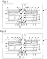
- FIG. 3 illustrates the invention
- Figures 1 and 2 illustrate embodiments that are not part of the claimed invention, each of which is set out in detail below:
- the barrel 1 comprises a monobloc subassembly 10 comprising a ratchet 2, a shaft 3, and a core 4, under a bridge 5.
- This monobloc subassembly 10 is pivoted at an upper bearing surface 13 in a bore 51 of the bridge 5 or a stone 52 of the bridge 5, and it comprises an upper shoulder 11 whose travel is limited by the lower surface. 53 of this bridge 5 or stone 52.
- the ratchet 2 is between this upper shoulder 11 and a lower shoulder 12 of the monobloc subassembly 10 at the core 4.
- This lower shoulder 12 limits the travel of an upper surface 61 of a drum 6. While the drum 6 pivots at a bore 62 with a cylindrical bearing surface 41 of the core 4.
- the shaft 3 is of smaller diameter than that of the core 4, and carries a hook 32 for the internal hooking of a spring 7, or it carries this spring 7 directly at a bearing surface 31 on which this spring 7 is fixed by friction or welding, or whatever.
- the drum 6 carries a lid 8 integral with the drum 6 and a bore 81 cooperates with a bearing 31 of the shaft 3.
- a lower surface 82 of this cover 8 is limited in movement by the upper surface 93 of a plate 9 or a stone 92 housed in a plate 9.
- the bore 91 of this plate 9 or of this stone 92 serves as a pivot at the reach 31 of the shaft 3.
- the one-piece subassembly 10 comprises a bearing 41 of the core 4, which is pivotable, in a bore 62 of the drum 6 also pivotally mounted.
- the monobloc subassembly 10 comprises a bearing 31 of the shaft 3, which is pivotable in a bore 81 of the cover 8 also pivotally mounted.
- the monobloc subassembly 10 comprises at its upper part, above the ratchet 2, a bearing surface 13, which is pivotable in a bore 51 of the bridge 5, or if appropriate the stone 52 of the bridge 5 which is fixed.
- the one-piece subassembly 10 has at its bottom part, below the cover 8, a bearing surface 31 of the shaft 3, which is pivotable in a bore 91 of the plate 9, or, if appropriate, of the stone 92 of the platinum 9 which is fixed.
- the frolicking of the drum 6 is limited in lower bearing relative to the ratchet 2, by the upper surface 61 of the drum 6 which is limited by the lower shoulder 12 of the monoblock subassembly 10, which is equivalent to the lower support of the ratchet 2.
- the fretting of the ratchet 2 is limited in lower support relative to the bridge 5, by the upper shoulder 11 of the monobloc subassembly 10 which is limited by the lower surface 53 of the bridge 5 or stone 52.
- the frog of the cover 8 is limited in upper support relative to the plate 9, by the lower surface 82 of the cover 8 which is limited by the upper surface 93 of the plate 9 or the stone 91.
- the bung diameter is not limited by anything other than the resistance of the material to the shear forces, the diameter of the shaft 3 either, which allows the realization of a very small shaft diameter, and the obtaining a very favorable K factor.
- the barrel 1 comprises a monobloc subassembly 10 gathering a shaft 3, and a core 4, under a bridge 5.
- This monobloc subassembly 10 receives, bearing on a shoulder 15, a ratchet 2, which is then crimped at the a rivet 16 of the core 4, to become integral in pivoting of this monobloc subassembly 10.
- This monobloc subassembly 10 is pivoted at an upper bearing surface 13 in a bore 51 of the bridge 5 or a stone 52 of the bridge 5, and the core 4 comprises an upper shoulder 11, whose stroke is limited by the lower surface 53 of this bridge 5 or of this stone 52.
- the ratchet 2 is between this upper shoulder 11 and a lower shoulder 12 of the core 4 of the monobloc subassembly 10.
- This lower shoulder 12 limits the travel of an upper surface 61 of a drum 6. While the drum 6 pivots at a bore 62 with a cylindrical bearing surface 41 of the core 4.
- the shaft 3 is of smaller diameter than that of the core 4, and carries a hook 32 for the internal hooking of a spring 7, or it carries this spring 7 directly at a bearing surface 31 on which this spring 7 is fixed by friction or welding, or whatever.
- the drum 6 carries a lid 8 integral with the drum 6 and a bore 81 cooperates with a bearing 31 of the shaft 3.
- a lower surface 82 of this cover 8 is limited in movement by the upper surface 93 of a plate 9 or a stone 92 housed in a plate 9.
- the bore 91 of this plate 9 or of this stone 92 serves as a pivot at the reach 31 of the shaft 3.
- the one-piece subassembly 10 comprises a bearing 41 of the core 4, which is pivotable, in a bore 62 of the drum 6 also pivotally mounted.
- the monobloc subassembly 10 comprises a bearing 31 of the shaft 3, which is pivotable in a bore 81 of the cover 8 also pivotally mounted.
- the one-piece subassembly 10 comprises at its upper part, above the ratchet 2, a bearing surface 13, which is pivotable in a bore 51 of the bridge 5, or the stone 52 of the bridge 5 which is fixed.
- the one-piece subassembly 10 has at its bottom part, below the cover 8, a bearing 31 of the shaft 3, which is pivotable in a bore 91 of the plate 9 or the stone 92 of the plate 9 which is fixed.
- the frolicking of the drum 6 is limited in lower bearing relative to the core 4, by the upper surface 61 of the drum 6 which is limited by the lower shoulder 12 of the core 4 of the monobloc subassembly 10.
- the fretting of the core 4 is limited in lower support relative to the bridge 5, by the upper shoulder 11 of the core 4 which is limited by the lower surface 53 of the bridge 5 or the stone 52.
- the frog of the cover 8 is limited in upper support relative to the plate 9, by the lower surface 82 of the cover 8 which is limited by the upper surface 93 of the plate 9 or the stone 91.
- the diameter of the core at the drum is not limited by anything other than the strength of the material shear forces, the diameter of the shaft 3 either, which allows the realization of a very small shaft diameter , and obtaining a very favorable K factor.
- the barrel 1 comprises a monobloc subassembly 10 including a ratchet 2 and a core 4, under a bridge 5.
- the core 4 defines at its inner part a gun, which has an outer bearing 41 and a housing or a bore 45 in which is driven a shaft 3, which thus becomes pivotally integral with the core 4.
- the shaft 3 can thus be very simple, in particular with a single cylindrical bearing surface 31, and the machining of a hook 32 is then easy and economical.
- This monobloc subassembly 10 is pivoted at an upper bearing surface 13 in a bore 51 of the bridge 5 or a stone 52 of the bridge 5, and it comprises an upper shoulder 11 whose travel is limited by the lower surface. 53 of this bridge 5 or stone 52.
- the ratchet 2 is between this upper shoulder 11 and a lower shoulder 12 of the monobloc subassembly 10, which is adjacent to the barrel of the core 4 and its cylindrical bearing 41.
- This lower shoulder 12 limits the travel of an upper surface 61 of a drum 6. While the drum 6 pivots at a bore 62 with a cylindrical bearing surface 41 of the core 4.
- the shaft 3 is of smaller diameter than that of the core 4, and carries a hook 32 for the internal hooking of a spring 7, or it carries this spring 7 directly at a bearing surface 31 on which this spring 7 is fixed by friction or welding, or whatever.
- the drum 6 carries a lid 8 integral with the drum 6 and a bore 81 cooperates with a bearing 31 of the shaft 3.
- a lower surface 82 of this cover 8 is limited in movement by the upper surface 93 of a plate 9 or a stone 92 housed in a plate 9.
- the bore 91 of this plate 9 or of this stone 92 serves as a pivot at the reach 31 of the shaft 3.
- the one-piece subassembly 10 comprises a bearing 41 of the core 4, which is pivotable, in a bore 62 of the drum 6 also pivotally mounted.
- the shaft 3 comprises a bearing 31 which is pivotable in a bore 81 of the cover 8 also pivotally mounted.
- the one-piece subassembly 10 comprises at its upper part, above the ratchet 2, a bearing surface 13, which is pivotable in a bore 51 of the bridge 5 or the stone 52 of the bridge 5 which is fixed.
- the shaft 3 comprises at its lower part, below the cover 8, a bearing 31 which is pivotable in a bore 91 of the plate 9 or the stone 92 of the plate 9 which is fixed.
- the frolicking of the drum 6 is limited in lower bearing relative to the ratchet 2, by the upper surface 61 of the drum 6 which is limited by the lower shoulder 12 of the monoblock subassembly 10, which is equivalent to the lower support of the ratchet 2.
- the fretting of the ratchet 2 is limited in lower bearing relative to the bridge 5, by the upper shoulder 11 of the monobloc subassembly 10 which is limited by the lower surface 53 of the bridge 5 or the stone 52.
- the frog of the cover 8 is limited in upper support relative to the plate 9, by the lower surface 82 of the cover 8 which is limited by the upper surface 93 of the plate 9 or the stone 91.
- the diameter of the core is not limited by anything other than the resistance of the material to the shear forces, the diameter of the shaft 3 either, which allows the realization of a very small diameter of tree, and obtaining a very favorable K factor.
- the shaft 3 has a threaded end which cooperates with a tapping which comprises the core 4 in the barrel, and which then replaces the bore 45.
- the first realization of the figure 1 is advantageous because the subassembly 10 monoblock under the bridge combines the functions of ratchet, shaft, and core, without machining complexity other than the hook 32 for hooking the spring 7. There are three occasions of frolic.
- the advantage of this construction is that there is no limit to the diameter of the core.
- the second achievement of the figure 2 is distinguished by the riveting of the ratchet on the tree, there are three times of frolicking. There is also no limit to the diameter of the core.
- the third achievement of the figure 3 is advantageous as regards the machining of the hook 32, inexpensive on a shaft without flange.
- the tree is driven (or screwed) into the ratchet, the pivoting drum is on the barrel of the ratchet, there are three times of frolicking. There is also no limit to the diameter of the core.
- the invention also relates to a watch movement 100, comprising at least one plate 9, and a bridge 5, and such a cylinder 1.
- the invention also relates to a watch 200 comprising such a movement 100.
Landscapes
- Physics & Mathematics (AREA)
- General Physics & Mathematics (AREA)
- Engineering & Computer Science (AREA)
- Metallurgy (AREA)
- Adornments (AREA)
- Micromachines (AREA)
- Harvester Elements (AREA)
Description
L'invention concerne un barillet d'horlogerie pour montage pivotant entre une platine et un pont, ladite platine comportant un premier alésage ou une première pierre comportant ledit premier alésage, ladite platine ou ladite première pierre comportant une surface supérieure tournée vers ledit pont, et ledit pont comportant un deuxième alésage ou une deuxième pierre comportant ledit deuxième alésage, ledit pont ou ladite deuxième pierre comportant une surface inférieure tournée vers ladite platine, ledit barillet comportant au moins un ressort logé entre un tambour pivotant et un couvercle et accroché entre, à son extrémité extérieure ledit tambour et à son extrémité intérieure un arbre lequel est solidaire en pivotement avec un rochet autour d'un axe de pivotement, ledit barillet comportant un sous-ensemble monobloc coaxial audit arbre et regroupant, autour d'un noyau , au moins ledit rochet ou/et ledit arbre.The invention relates to a watch cylinder for pivotally mounting between a plate and a bridge, said plate comprising a first bore or a first stone comprising said first bore, said plate or said first stone having an upper surface facing said bridge, and said bridge comprising a second bore or a second stone comprising said second bore, said bridge or said second stone having a lower surface facing said plate, said barrel comprising at least one spring housed between a pivoting drum and a cover and hung between, to its outer end said drum and at its inner end a shaft which is pivotally integral with a ratchet about a pivot axis, said cylinder having a monobloc sub-assembly coaxial with said shaft and grouping around a core, at least said ratchet and / or said shaft.
L'invention concerne encore un mouvement d'horlogerie, comportant au moins une platine et un pont et un tel barillet.The invention also relates to a watch movement, comprising at least one plate and a bridge and such a cylinder.
L'invention concerne encore une montre comportant un tel mouvement.The invention also relates to a watch comprising such a movement.
L'invention concerne le domaine des mécanismes d'horlogerie, et plus particulièrement les mécanismes de stockage d'énergie, du type barillet moteur, barillet de sonnerie, ou similaire.The invention relates to the field of watch mechanisms, and more particularly the energy storage mechanisms, the engine barrel type, barrel striking, or the like.
Pour augmenter la réserve de marche, par augmentation du nombre de tours d'un ressort de barillet, fixé à son extrémité intérieure sur une bonde constituée, ou bien par un arbre, généralement cylindrique, ou bien par un noyau plus massif, une solution consiste en une diminution du diamètre de l'arbre de barillet et du noyau associé, de façon à augmenter la place disponible dans le tambour pour le ressort.To increase the power reserve, by increasing the number of turns of a mainspring, fixed at its inner end to a bung, or by a generally cylindrical shaft, or by a more massive core, a solution consists of in a decrease in the diameter of the barrel shaft and the associated core, so as to increase the space available in the drum for the spring.
Le rapport du rayon de bonde par rapport à l'épaisseur du ressort est usuellement compris entre 10 et 20, et l'invention se propose d'abaisser ce rapport en-dessous de 10, et préférentiellement dans la plage comprise entre 5 et 10.The ratio of the bead radius to the thickness of the spring is usually between 10 and 20, and the invention proposes to lower this ratio below 10, and preferably in the range between 5 and 10.
Le dimensionnement ne doit pas être fait à la légère, en effet un risque de casse existe si le diamètre de bonde est trop faible.The dimensioning should not be done lightly, indeed a risk of breakage exists if the bung diameter is too small.
Dans l'architecture classique des barillets, un rochet est monté axialement sur un axe de barillet ou sur une bonde, par l'intermédiaire d'un carré, le rochet étant généralement fixé par une vis axiale. La dimension de cette vis et celle du carré conditionnent donc un diamètre minimal d'une portée de pivotement. Un épaulement jointif à cette portée de pivotement limite l'ébat axial de l'arbre ou de la bonde par rapport à une platine ou à un pont porteur d'une pierre ou similaire.In the conventional architecture of the barrels, a ratchet is mounted axially on a barrel axis or on a bung, via a square, the ratchet being generally fixed by an axial screw. The size of this screw and that of the square thus condition a minimum diameter of a pivoting surface. A shoulder abutting with this pivoting surface limits axial fretting of the shaft or the bung relative to a plate or bridge carrying a stone or the like.
On ne peut en particulier pas se contenter de réduire l'ensemble des dimensionnements, car les sections de matière sont alors insuffisantes pour assurer la tenue en fatigue.In particular, it is not enough to reduce all the sizing, because the sections of material are then insufficient to ensure fatigue resistance.
Il s'agit donc de concilier un diamètre d'arbre le plus réduit possible, pour autoriser la plus grande réserve de marche possible, et une rigidité de l'entraînement du rochet.It is therefore a question of reconciling a tree diameter as small as possible, to allow the greatest possible power reserve, and a rigidity of the ratchet drive.
Le document
Le document
Le document
Le document
Le document
Le document
Le document
Le document
L'invention se propose d'améliorer la conception de barillets conçus pour une grande réserve de marche, en leur procurant une bonne rigidité, notamment au niveau du rochet, tout en conservant un nombre de composants réduit, et un coût d'usinage acceptable, ou, de préférence, plus économique que sur les barillets connus.The invention proposes to improve the design of barrels designed for a large power reserve, giving them good rigidity, particularly at the ratchet, while retaining a reduced number of components, and an acceptable machining cost, or, preferably, more economical than on known barrels.
L'invention concerne ainsi un barillet d'horlogerie selon la revendication 1.The invention thus relates to a watch cylinder according to
Selon une caractéristique particulière de l'invention, ledit ressort est réalisé dans un alliage multiphasé à base cobalt-nickel-chrome, comportant de 44 à 46% de cobalt, de 20 à 22% de nickel, de 17 à 19% de chrome, de 4 à 6% de fer, de 3 à 5% de tungstène, de 3 à 5% de molybdène, de 0 à 2% de titane, de 0 à 1% de béryllium, et de module d'Young compris entre 200 et 240 GPa et un module de cisaillement compris entre 80 et 100 GPa, en ledit ressort a un rapport largeur/épaisseur compris entre 3 et 23, et le rapport entre le rayon maximal d'une portée d'appui du ressort dudit arbre et l'épaisseur dudit ressort est compris entre 3 et 9.According to a particular characteristic of the invention, said spring is made of a cobalt-nickel-chromium-based multiphase alloy comprising from 44 to 46% of cobalt, from 20 to 22% of nickel, from 17 to 19% of chromium, from 4 to 6% of iron, from 3 to 5% of tungsten, from 3 to 5% of molybdenum, from 0 to 2% of titanium, from 0 to 1% of beryllium, and from Young's modulus of between 200 and 240 GPa and a shear modulus between 80 and 100 GPa, in said spring has a width / thickness ratio between 3 and 23, and the ratio between the maximum radius of a bearing surface of the spring of said shaft and the the thickness of said spring is between 3 and 9.
L'invention concerne encore un mouvement d'horlogerie, comportant au moins une platine et un pont, selon la revendication 8.The invention further relates to a clockwork movement, comprising at least one plate and a bridge, according to
L'invention concerne encore une montre comportant un tel mouvement.The invention also relates to a watch comprising such a movement.
D'autres caractéristiques et avantages de l'invention apparaîtront à la lecture de la description détaillée qui va suivre, en référence aux dessins annexés, où :
- la
figure 1 représente, de façon schématisée et en coupe par son axe de pivotement, un barillet selon une première réalisations qui ne fait pas partie de l'invention revendiquée ; - la
figure 2 représente, de façon schématisée et en coupe par son axe de pivotement, un barillet selon une deuxième réalisation qui ne fait pas partie de l'invention revendiquée ; - la
figure 3 représente, de façon schématisée et en coupe par son axe de pivotement, un barillet selon une troisième réalisation propre à l'invention ; - la
figure 4 représente, de façon schématisée en blocs, une pièce d'horlogerie comportant un mouvement comportant lui-même un barillet selon l'invention.
- the
figure 1 represents, schematically and in section through its pivot axis, a barrel according to a first embodiment which does not form part of the claimed invention; - the
figure 2 represents, schematically and in section through its pivot axis, a cylinder according to a second embodiment which does not form part of the claimed invention; - the
figure 3 represents, schematically and in section through its pivot axis, a cylinder according to a third embodiment of the invention; - the
figure 4 represents, schematically in blocks, a timepiece comprising a movement comprising itself a cylinder according to the invention.
L'invention concerne le domaine des mécanismes d'horlogerie, et plus particulièrement les mécanismes de stockage d'énergie, du type barillet moteur, barillet de sonnerie, ou similaire.The invention relates to the field of watch mechanisms, and more particularly the energy storage mechanisms, the engine barrel type, barrel striking, or the like.
L'invention concerne ainsi un barillet d'horlogerie 1 pour montage pivotant entre une platine 9 et un pont 5, et comportant au moins un ressort 7. Ce ressort 7 est logé entre un tambour 6 pivotant et un couvercle 8, et accroché entre, à son extrémité extérieure le tambour 6 et à son extrémité intérieure un arbre 3. L'arbre 3 est solidaire en pivotement avec un rochet 2 autour d'un axe de pivotement D.The invention thus relates to a
Selon l'invention, le barillet 1 comporte un sous-ensemble monobloc 10 coaxial à l'arbre 3 et regroupant, autour d'un noyau 4, au moins le rochet 2 ou/et l'arbre 3.According to the invention, the
Ce sous-ensemble monobloc 10 est pivoté au niveau d'une portée supérieure 13 dans un alésage 51 du pont 5 ou d'une pierre 52 que comporte le pont 5, et comporte un épaulement supérieur 11, dont la course est limitée par une surface inférieure 53 du pont 5 ou de la pierre 52. Le rochet 2 est compris entre l'épaulement supérieur 11 et un épaulement inférieur 12 que comporte le sous-ensemble monobloc 10 au niveau du noyau 4. Cet épaulement inférieur 12 limite la course d'une surface supérieure 61 du tambour 6. Ce tambour 6 pivote au niveau d'un alésage 62 qu'il comporte avec une portée cylindrique 41 du noyau 4.This
L'arbre 3 comporte une portée 31 de préférence cylindrique, qui est de préférence de diamètre inférieur à celui de la portée cylindrique 41 du noyau 4. L'arbre 3 porte le ressort 7, ou bien au niveau de sa portée 31, sur laquelle le ressort 7 est immobilisé par friction ou soudé, ou bien sur un crochet 32 que comporte l'arbre 3 autour d'une telle portée 31. L'arbre 3 est monté pivotant dans un alésage 91 de la platine 9 ou d'une pierre 92 que comporte la platine 9. Dans une réalisation préférée, la portée 31 se prolonge, et constitue la surface de pivotement dans cet alésage 91 ou cette pierre 92..The
Le tambour 6 porte un couvercle 8, de préférence mais non nécessairement solidaire en pivotement du tambour 6, et dont un alésage 81 coopère avec une portée 31 de l'arbre 3. Une surface inférieure 82 du couvercle 8 est limitée en débattement par une surface supérieure 93 de la platine 9 ou d'une pierre 92 logée dans la platine 9, un alésage 91 de la platine 9 ou de la pierre 92 servant de pivot à la portée 31 de l'arbre 3.The
L'ébat du tambour 6 est limité en appui inférieur par rapport au rochet 2, par une surface supérieure 61 du tambour 6 qui est limitée par un épaulement inférieur 12 du sous-ensemble monobloc 10.The frolicking of the
L'ébat du rochet 2 est limité en appui inférieur par rapport au pont 5, par un épaulement supérieur 11 du sous-ensemble monobloc 10 qui est limité par une surface inférieure 53 du pont 5 ou d'une pierre 52 que comporte le pont 5.The fretting of the
L'ébat du couvercle 8 est limité en appui supérieur par rapport à la platine 9, par une surface inférieure 82 du couvercle 8 qui est limitée par une surface supérieure 93 de la platine 9 ou d'une pierre 91 que comporte la platine 9.The frog of the
Le ressort moteur peut être réalisé en différents matériaux : acier au carbone, acier inoxydable, « Nivaflex® », silicium, DLC, quartz, verre, ou similaire. Dans une application particulière, le ressort 7 est réalisé dans un alliage multiphasé à base cobalt-nickel-chrome, comportant de 44 à 46% de cobalt, de 20 à 22% de nickel, de 17 à 19% de chrome, de 4 à 6% de fer, de 3 à 5% de tungstène, de 3 à 5% de molybdène, de 0 à 2% de titane, de 0 à 1% de béryllium, et de module d'Young compris entre 200 et 240 GPa et un module de cisaillement compris entre 80 et 100 GPa. Ce ressort 7 a de préférence un rapport largeur/épaisseur compris entre 3 et 23, et plus particulièrement entre 9 et 21.The motor spring can be made of different materials: carbon steel, stainless steel, "Nivaflex®", silicon, DLC, quartz, glass, or similar. In a particular application, the
Et le rayon maximal de la portée 31 de l'arbre 3 (sans tenir compte de la surépaisseur éventuelle propre à un crochet 32), réalisé en acier ou en acier inoxydable, par exemple en acier inoxydable trempable 4C27A (aussi dénommé selon les différentes normes 1.4197, ASTM 420F, ou DIN X22 CrMoNiS 13 1), par rapport à l'axe de pivotement D est inférieur à neuf fois l'épaisseur maximale du ressort 7. En particulier les réalisations illustrées permettent d'obtenir un rapport entre le rayon maximal de la portée 31 de l'arbre 3 et l'épaisseur du ressort 7 compris entre 3 et 9, et de préférence entre 4 et 6, de préférence voisin de 5.And the maximum radius of the bearing 31 of the shaft 3 (without taking into account the possible extra thickness specific to a hook 32), made of steel or stainless steel, for example hardened stainless steel 4C27A (also named according to different standards 1.4197, ASTM 420F, or
La
Le barillet 1 comporte un sous-ensemble monobloc 10 regroupant un rochet 2, un arbre 3, et un noyau 4, sous un pont 5.The
Cet sous-ensemble monobloc 10 est pivoté au niveau d'une portée supérieure 13 dans un alésage 51 du pont 5 ou d'une pierre 52 du pont 5, et il comporte un épaulement supérieur 11, dont la course est limitée par la surface inférieure 53 de cette ce pont 5 ou de cette pierre 52. Le rochet 2 est compris entre cet épaulement supérieur 11 et un épaulement inférieur 12 du sous-ensemble monobloc 10 au niveau du noyau 4.This
Cet épaulement inférieur 12 limite la course d'une surface supérieure 61 d'un tambour 6. Tandis que le tambour 6 pivote au niveau d'un alésage 62 avec une portée cylindrique 41 du noyau 4.This
L'arbre 3 est de diamètre inférieur à celui du noyau 4, et porte un crochet 32 d'accrochage interne d'un ressort 7, ou bien porte directement ce ressort 7 au niveau d'une portée 31 sur laquelle ce ressort 7 est fixé par friction ou par soudage, ou autre.The
Le tambour 6 porte un couvercle 8 solidaire de ce tambour 6 et dont un alésage 81 coopère avec une portée 31 de l'arbre 3.The
Une surface inférieure 82 de ce couvercle 8 est limitée en débattement par la surface supérieure 93 d'une platine 9 ou d'une pierre 92 logée dans une platine 9. L'alésage 91 de cette platine 9 ou de cette pierre 92 sert de pivot à la portée 31 de l'arbre 3.A
Le sous-ensemble monobloc 10 comporte une portée 41 du noyau 4, qui est pivotante, dans un alésage 62 du tambour 6 également monté pivotant.The one-
Le sous-ensemble monobloc 10 comporte une portée 31 de l'arbre 3, qui est pivotante dans un alésage 81 du couvercle 8 également monté pivotant.The
Le sous-ensemble monobloc 10 comporte à sa partie supérieure, au-dessus du rochet 2, une portée 13, qui est pivotante dans un alésage 51 du pont 5, ou le cas échéant de la pierre 52 du pont 5 qui est fixe.The
Le sous-ensemble monobloc 10 comporte à sa partie inférieure, au-dessous du couvercle 8, une portée 31 de l'arbre 3, qui est pivotante dans un alésage 91 de la platine 9, ou le cas échéant de la pierre 92 de la platine 9 qui est fixe.The one-
L'ébat du tambour 6 est limité en appui inférieur par rapport au rochet 2, par la surface supérieure 61 du tambour 6 qui est limitée par l'épaulement inférieur 12 du sous-ensemble monobloc 10, qui équivaut à l'appui inférieur du rochet 2.The frolicking of the
L'ébat du rochet 2 est limité en appui inférieur par rapport au pont 5, par l'épaulement supérieur 11 du sous-ensemble monobloc 10 qui est limité par la surface inférieure 53 du pont 5 ou de de la pierre 52.The fretting of the
L'ébat du couvercle 8 est limité en appui supérieur par rapport à la platine 9, par la surface inférieure 82 du couvercle 8 qui est limitée par la surface supérieure 93 de la platine 9 ou de la pierre 91.The frog of the
Le diamètre de bonde n'est pas limité par autre chose que la résistance du matériau aux efforts de cisaillement, le diamètre de l'arbre 3 non plus, ce qui autorise la réalisation d'un très petit diamètre d'arbre, et l'obtention d'un facteur K très favorable.The bung diameter is not limited by anything other than the resistance of the material to the shear forces, the diameter of the
Le barillet 1 comporte un sous-ensemble monobloc 10 regroupant un arbre 3, et un noyau 4, sous un pont 5. Cet sous-ensemble monobloc 10 reçoit, en appui sur un épaulement 15, un rochet 2, qui est ensuite serti au niveau d'une rivure 16 du noyau 4, pour devenir solidaire en pivotement de cet sous-ensemble monobloc 10.The
Ce sous-ensemble monobloc 10 est pivoté au niveau d'une portée supérieure 13 dans un alésage 51 du pont 5 ou d'une pierre 52 du pont 5, et le noyau 4 comporte un épaulement supérieur 11, dont la course est limitée par la surface inférieure 53 de ce pont 5 ou de cette pierre 52. Le rochet 2 est compris entre cet épaulement supérieur 11 et un épaulement inférieur 12 du noyau 4 du sous-ensemble monobloc 10.This
Cet épaulement inférieur 12 limite la course d'une surface supérieure 61 d'un tambour 6. Tandis que le tambour 6 pivote au niveau d'un alésage 62 avec une portée cylindrique 41 du noyau 4.This
L'arbre 3 est de diamètre inférieur à celui du noyau 4, et porte un crochet 32 d'accrochage interne d'un ressort 7, ou bien porte directement ce ressort 7 au niveau d'une portée 31 sur laquelle ce ressort 7 est fixé par friction ou par soudage, ou autre.The
Le tambour 6 porte un couvercle 8 solidaire de ce tambour 6 et dont un alésage 81 coopère avec une portée 31 de l'arbre 3.The
Une surface inférieure 82 de ce couvercle 8 est limitée en débattement par la surface supérieure 93 d'une platine 9 ou d'une pierre 92 logée dans une platine 9. L'alésage 91 de cette platine 9 ou de cette pierre 92 sert de pivot à la portée 31 de l'arbre 3.A
Le sous-ensemble monobloc 10 comporte une portée 41 du noyau 4, qui est pivotante, dans un alésage 62 du tambour 6 également monté pivotant.The one-
Le sous-ensemble monobloc 10 comporte une portée 31 de l'arbre 3, qui est pivotante dans un alésage 81 du couvercle 8 également monté pivotant.The
Le sous-ensemble monobloc 10 comporte à sa partie supérieure, au-dessus du rochet 2, une portée 13, qui est pivotante dans un alésage 51 du pont 5, ou de la pierre 52 du pont 5 qui est fixe.The one-
Le sous-ensemble monobloc 10 comporte à sa partie inférieure, au-dessous du couvercle 8, une portée 31 de l'arbre 3, qui est pivotante dans un alésage 91 de la de la platine 9 ou de la pierre 92 de la platine 9 qui est fixe.The one-
Cette réalisation a trois reprises d'ébat.This achievement has three times frolic.
L'ébat du tambour 6 est limité en appui inférieur par rapport au noyau 4, par la surface supérieure 61 du tambour 6 qui est limitée par l'épaulement inférieur 12 du noyau 4 du sous-ensemble monobloc 10.The frolicking of the
L'ébat du noyau 4 est limité en appui inférieur par rapport au pont 5, par l'épaulement supérieur 11 du noyau 4 qui est limité par la surface inférieure 53 du pont 5 ou de la pierre 52.The fretting of the
L'ébat du couvercle 8 est limité en appui supérieur par rapport à la platine 9, par la surface inférieure 82 du couvercle 8 qui est limitée par la surface supérieure 93 de la platine 9 ou de la pierre 91.The frog of the
Le diamètre du noyau au niveau du tambour n'est pas limité par autre chose que la résistance du matériau aux efforts de cisaillement, le diamètre de l'arbre 3 non plus, ce qui autorise la réalisation d'un très petit diamètre d'arbre, et l'obtention d'un facteur K très favorable.The diameter of the core at the drum is not limited by anything other than the strength of the material shear forces, the diameter of the
Le barillet 1 comporte un sous-ensemble monobloc 10 regroupant un rochet 2 et un noyau 4, sous un pont 5. Le noyau 4 définit à sa partie intérieure un canon, qui comporte une portée externe 41 et un logement ou un alésage 45 dans lequel est chassé un arbre 3, qui devient ainsi solidaire en pivotement avec ce noyau 4.The
L'arbre 3 peut ainsi être très simple, notamment comporter une unique portée 31 cylindrique, et l'usinage d'un crochet 32 est alors facile et économique.The
Cet sous-ensemble monobloc 10 est pivoté au niveau d'une portée supérieure 13 dans un alésage 51 du pont 5 ou d'une pierre 52 du pont 5, et il comporte un épaulement supérieur 11, dont la course est limitée par la surface inférieure 53 de ce pont 5 ou de cette pierre 52. Le rochet 2 est compris entre cet épaulement supérieur 11 et un épaulement inférieur 12 du sous-ensemble monobloc 10, qui est adjacent au canon du noyau 4 et à sa portée cylindrique 41.This
Cet épaulement inférieur 12 limite la course d'une surface supérieure 61 d'un tambour 6. Tandis que le tambour 6 pivote au niveau d'un alésage 62 avec une portée cylindrique 41 du noyau 4.This
L'arbre 3 est de diamètre inférieur à celui du noyau 4, et porte un crochet 32 d'accrochage interne d'un ressort 7, ou bien porte directement ce ressort 7 au niveau d'une portée 31 sur laquelle ce ressort 7 est fixé par friction ou par soudage, ou autre.The
Le tambour 6 porte un couvercle 8 solidaire de ce tambour 6 et dont un alésage 81 coopère avec une portée 31 de l'arbre 3.The
Une surface inférieure 82 de ce couvercle 8 est limitée en débattement par la surface supérieure 93 d'une platine 9 ou d'une pierre 92 logée dans une platine 9. L'alésage 91 de cette platine 9 ou de cette pierre 92 sert de pivot à la portée 31 de l'arbre 3.A
Le sous-ensemble monobloc 10 comporte une portée 41 du noyau 4, qui est pivotante, dans un alésage 62 du tambour 6 également monté pivotant.The one-
L'arbre 3 comporte une portée 31 qui est pivotante dans un alésage 81 du couvercle 8 également monté pivotant.The
Le sous-ensemble monobloc 10 comporte à sa partie supérieure, au-dessus du rochet 2, une portée 13, qui est pivotante dans un alésage 51 du pont 5 ou de la pierre 52 du pont 5 qui est fixe.The one-
L'arbre 3 comporte à sa partie inférieure, au-dessous du couvercle 8, une portée 31 qui est pivotante dans un alésage 91 de la platine 9 ou de la pierre 92 de la platine 9 qui est fixe.The
L'ébat du tambour 6 est limité en appui inférieur par rapport au rochet 2, par la surface supérieure 61 du tambour 6 qui est limitée par l'épaulement inférieur 12 du sous-ensemble monobloc 10, qui équivaut à l'appui inférieur du rochet 2.The frolicking of the
L'ébat du rochet 2 est limité en appui inférieur par rapport au pont 5, par l'épaulement supérieur 11 du sous-ensemble monobloc 10 qui est limité par la surface inférieure 53 du pont 5 ou de la pierre 52.The fretting of the
L'ébat du couvercle 8 est limité en appui supérieur par rapport à la platine 9, par la surface inférieure 82 du couvercle 8 qui est limitée par la surface supérieure 93 de la platine 9 ou de la pierre 91.The frog of the
Le diamètre du noyau n'est pas limité par autre chose que la résistance du matériau aux efforts de cisaillement, le diamètre de l'arbre 3 non plus, ce qui autorise la réalisation d'un très petit diamètre d'arbre, et l'obtention d'un facteur K très favorable.The diameter of the core is not limited by anything other than the resistance of the material to the shear forces, the diameter of the
Dans une autre réalisation encore, très voisine de celle de la
En somme, la première réalisation de la
La deuxième réalisation de la
La troisième réalisation de la
L'invention concerne encore un mouvement 100 d'horlogerie, comportant au moins une platine 9, et un pont 5, et un tel barillet 1.The invention also relates to a
L'invention concerne encore une montre 200 comportant un tel mouvement 100.The invention also relates to a
Claims (9)
- Timepiece barrel (1) for pivotal assembly between a plate (9) and a bar (5), said plate (9) including a first bore (91) or a first jewel (92) comprising said first bore (91), said plate (9) or said first jewel (92) comprising an upper surface (93) facing said bar (5), and said bar (5) comprising a second bore (51) or a second jewel (52) comprising said second bore (51), said bar (5) or said second jewel (52) comprising a lower surface (53) facing said plate (9), said barrel (1) including at least one spring (7) housed between a pivoting drum (6) and a cover (8) and hooked between said drum (6) at the outer end thereof and an arbor (3) at the inner end thereof, said arbor pivoting integrally with a ratchet (2) about a pivot axis (D), said barrel (1) including a one-piece sub-assembly (10) coaxial with said arbor (3) and grouping together, about a core (4), at least said ratchet (2) and/or said arbor (3), characterized in that said one-piece sub-assembly (10) comprises said ratchet (2) and said core (4), which defines at the lower part thereof a pipe, which includes an outer bearing surface (41) on which said drum (6) is pivotally guided at a third bore (62) comprised in said drum, and said pipe also includes a fourth bore (45) into which is pressed said arbor (3) integral in rotation with said core (4).
- Barrel (1) according to claim 1, characterized in that said one-piece sub-assembly (10) includes an upper bearing surface (13) arranged to pivot, depending on the case, in said second bore (51) of said bar (5) or of said second jewel (52), and in that said one-piece sub-assembly (10) also includes an upper shoulder (11), whose travel is limited by said lower surface (53) of said bar (5) or of said second jewel (52), and in that said ratchet (2) is arranged between said upper shoulder (11) and a lower shoulder (12) comprised in said one-piece sub-assembly (10) and which is adjacent to said pipe of said core (4) and to said outer bearing surface (41) of said pipe (4), said lower shoulder (12) being arranged to limit the travel of an upper surface (61) of said drum (6).
- Barrel (1) according to claim 1 or 2, characterized in that said arbor (3) is of smaller diameter than that of said core (4), and bears a hook (32) for internal hooking of a said spring (7).
- Barrel (1) according to claim 1 or 2, characterized in that said arbor (3) is of smaller diameter than that of said core (4), and directly carries a said spring (7) on a bearing surface (31) on which said spring (7) is fixed by friction or by welding.
- Barrel (1) according to any of claims 1 to 4, characterized in that said drum (6) carries said cover (8) which is integral with said drum (6) and includes a fifth bore (81) cooperating with a bearing surface (31) of said arbor (3) and the travel of a lower surface (82) of said cover (8) is limited by said upper surface (93), said bearing surface (31) of said arbor (3) being arranged to pivot, depending on the case, in said bore (91) of said plate (9) or of said first jewel (92).
- Barrel (1) according to any of claims 1 to 5, characterized in that said arbor (3) includes a single cylindrical bearing surface (31).
- Barrel (1) according to any of claims 1 to 6, characterized in that said spring (7) is made of a multiphase, cobalt-nickel-chromium based alloy, comprising 44 to 46% cobalt, 20 to 22% nickel, 17 to 19% chromium, 4 to 6 % iron, 3 to 5% tungsten, 3 to 5% molybdenum, 0 to 2% titanium, 0 to 1% beryllium, and having a Young's modulus comprised between 200 and 240 GPa and a shear modulus comprised between 80 and 100 GPa, in that said spring (7) has a width to thickness ratio of between 3 and 23, and in that the ratio between the maximum radius of a bearing surface (31) of the spring of said arbor (3) and the thickness of said spring (7) is between 3 and 9.
- Timepiece movement (100) including at least one plate (9) and a bar (5), said plate (9) comprising a first bore (91) or a first jewel (92) comprising said first bore (91), said plate (9) or said first jewel (92) comprising an upper surface (93) facing said bar (5), and said bar (5) comprising a second bore (51) or a second jewel (52) comprising said second bore (51), said bar (5) or said second jewel (52) comprising a lower surface (53) facing said plate (9) and a barrel (1) according to any of claims 1 to 7 mounted between said plate (9) and said bar (5).
- Watch (200) including a movement (100) according to the preceding claim.
Priority Applications (7)
| Application Number | Priority Date | Filing Date | Title |
|---|---|---|---|
| EP12197741.7A EP2746865B1 (en) | 2012-12-18 | 2012-12-18 | Timepiece barrel |
| PCT/EP2013/071988 WO2014095125A1 (en) | 2012-12-18 | 2013-10-21 | Timepiece barrel |
| CN201380066012.8A CN104871094B (en) | 2012-12-18 | 2013-10-21 | Clockwork feed box |
| JP2015537294A JP5960923B2 (en) | 2012-12-18 | 2013-10-21 | Timer barrel |
| RU2015129573A RU2629155C2 (en) | 2012-12-18 | 2013-10-21 | Clockwork motor |
| US14/428,079 US9367037B2 (en) | 2012-12-18 | 2013-10-21 | Timepiece barrel |
| HK16101508.5A HK1213644A1 (en) | 2012-12-18 | 2016-02-11 | Timepiece barrel |
Applications Claiming Priority (1)
| Application Number | Priority Date | Filing Date | Title |
|---|---|---|---|
| EP12197741.7A EP2746865B1 (en) | 2012-12-18 | 2012-12-18 | Timepiece barrel |
Publications (2)
| Publication Number | Publication Date |
|---|---|
| EP2746865A1 EP2746865A1 (en) | 2014-06-25 |
| EP2746865B1 true EP2746865B1 (en) | 2016-03-02 |
Family
ID=47552769
Family Applications (1)
| Application Number | Title | Priority Date | Filing Date |
|---|---|---|---|
| EP12197741.7A Active EP2746865B1 (en) | 2012-12-18 | 2012-12-18 | Timepiece barrel |
Country Status (7)
| Country | Link |
|---|---|
| US (1) | US9367037B2 (en) |
| EP (1) | EP2746865B1 (en) |
| JP (1) | JP5960923B2 (en) |
| CN (1) | CN104871094B (en) |
| HK (1) | HK1213644A1 (en) |
| RU (1) | RU2629155C2 (en) |
| WO (1) | WO2014095125A1 (en) |
Families Citing this family (2)
| Publication number | Priority date | Publication date | Assignee | Title |
|---|---|---|---|---|
| JP7133909B2 (en) * | 2016-07-04 | 2022-09-09 | ロレックス・ソシエテ・アノニム | Watch assembly manufacturing method and watch assembly obtained by said manufacturing method |
| JP6787098B2 (en) * | 2016-12-13 | 2020-11-18 | セイコーエプソン株式会社 | How to disengage watch movements, mechanical watches and claw levers |
Family Cites Families (22)
| Publication number | Priority date | Publication date | Assignee | Title |
|---|---|---|---|---|
| US168581A (en) * | 1875-10-11 | Improvement in barrel-arbors for watches | ||
| CH15286A (en) * | 1897-09-15 | 1898-04-30 | Giuseppe Danasino | Advanced mainspring watch movement |
| US730103A (en) * | 1903-01-13 | 1903-06-02 | Lewis A Erickson | Watch-barrel. |
| US804728A (en) * | 1905-03-25 | 1905-11-14 | Illinois Watch Company | Watch-barrel. |
| US978613A (en) * | 1909-07-31 | 1910-12-13 | Keystone Watch Case Company | Watch-barrel. |
| US996499A (en) * | 1910-11-25 | 1911-06-27 | Robert L Marshall | Safety spring-barrel. |
| US1033020A (en) * | 1911-05-31 | 1912-07-16 | Western Clock Mfg Company | Clock-spring barrel. |
| CH83330A (en) * | 1919-05-26 | 1919-12-01 | Co Beaulieu Watch | Watch movement |
| US1561673A (en) * | 1924-04-03 | 1925-11-17 | Ulery Clarence Everett | Clock arbor or shaft |
| GB647819A (en) * | 1944-12-12 | 1950-12-20 | Elgin Nat Watch Co | Cobalt chromium nickel base alloy |
| FR1034443A (en) * | 1950-04-01 | 1953-07-23 | Stainless steel watch spring with high resistance to fatigue and method for its manufacture | |
| JPS446779Y1 (en) * | 1966-02-01 | 1969-03-12 | ||
| CH1838572A4 (en) | 1972-12-18 | 1974-12-31 | ||
| CH607738B (en) | 1975-10-21 | Ebauchesfabrik Eta Ag | ARBRE DE BARILLET EXTRACTIBLE POUR MOUVEMENT DE MONTRE. | |
| JPS5251973A (en) * | 1976-10-18 | 1977-04-26 | Ebauchesfabrik Eta Ag | Drawable incense casket core |
| JP3041585B2 (en) * | 1995-04-28 | 2000-05-15 | セイコーインスツルメンツ株式会社 | Mainspring manufacturing method |
| CH702035B1 (en) * | 2006-10-20 | 2011-04-29 | Eterna Sa Fabrique D Horlogerie | Timepiece. |
| CH700058B1 (en) * | 2008-12-15 | 2013-09-13 | Francois Durafourg | Assembly including a winding ratchet attached to a barrel arbor and barrel shaft for this set. |
| CH702994B1 (en) * | 2010-04-26 | 2015-07-31 | Eterna Sa Fabrique D Horlogerie | Timepiece comprising a barrel mounted on a barrel bridge. |
| EP2560057B1 (en) * | 2011-08-17 | 2014-04-02 | ETA SA Manufacture Horlogère Suisse | Timepiece movement with reduced height and large power reserve |
| EP2570864B1 (en) * | 2011-09-15 | 2018-11-14 | Blancpain S.A. | Clock barrel with reduced core diameter |
| EP2634649B1 (en) * | 2012-02-29 | 2017-07-12 | ETA SA Manufacture Horlogère Suisse | Inexpensive timepiece barrel |
-
2012
- 2012-12-18 EP EP12197741.7A patent/EP2746865B1/en active Active
-
2013
- 2013-10-21 CN CN201380066012.8A patent/CN104871094B/en active Active
- 2013-10-21 US US14/428,079 patent/US9367037B2/en active Active
- 2013-10-21 WO PCT/EP2013/071988 patent/WO2014095125A1/en active Application Filing
- 2013-10-21 JP JP2015537294A patent/JP5960923B2/en active Active
- 2013-10-21 RU RU2015129573A patent/RU2629155C2/en active
-
2016
- 2016-02-11 HK HK16101508.5A patent/HK1213644A1/en unknown
Also Published As
| Publication number | Publication date |
|---|---|
| WO2014095125A1 (en) | 2014-06-26 |
| CN104871094B (en) | 2017-10-13 |
| EP2746865A1 (en) | 2014-06-25 |
| JP5960923B2 (en) | 2016-08-02 |
| US9367037B2 (en) | 2016-06-14 |
| CN104871094A (en) | 2015-08-26 |
| HK1213644A1 (en) | 2016-07-08 |
| RU2629155C2 (en) | 2017-08-24 |
| JP2016512596A (en) | 2016-04-28 |
| US20150253731A1 (en) | 2015-09-10 |
| RU2015129573A (en) | 2017-01-23 |
Similar Documents
| Publication | Publication Date | Title |
|---|---|---|
| EP2936253B1 (en) | Clock barrel | |
| EP2756360B1 (en) | Timepiece barrel assembly having a small core diameter | |
| EP2634649B1 (en) | Inexpensive timepiece barrel | |
| CH702035B1 (en) | Timepiece. | |
| EP2746865B1 (en) | Timepiece barrel | |
| CH714365B1 (en) | One-way wheel clockwork mobile. | |
| EP2756359B1 (en) | Clock barrel assembly with reduced core diameter | |
| EP2746866B1 (en) | Timepiece barrel | |
| EP2570864B1 (en) | Clock barrel with reduced core diameter | |
| WO2013037864A1 (en) | Timepiece barrel assembly having a small core diameter | |
| EP2746867B1 (en) | Timepiece barrel | |
| CH707407A2 (en) | Clockwork barrel e.g. striking barrel, for use in clockwork movement of watch, has shaft pivotingly secured to ratchet around axis, and single-block subassembly coaxial to shaft, where subassembly groups ratchet and/or shaft around core | |
| CH702994A2 (en) | Timepiece. | |
| CH707408A2 (en) | Clockwork barrel e.g. striking barrel, for use in clockwork movement of watch, has shaft pivotingly secured to ratchet around pivoting axis, and single-block subassembly, coaxial to shaft, grouping ratchet and/or shaft around core | |
| CH707409A2 (en) | Clockwork barrel e.g. striking barrel, for use in clockwork movement of watch, has flange limiting axial clearance of drum, and flange carrying driving unit to pivotingly drive ratchet so as to be axially free according to direction of axis | |
| CH707410A2 (en) | Clockwork barrel e.g. striking barrel, for use in watch's clockwork movement, has shaft including protruding hook to fix spring and protruding/re-entrant driving unit cooperating with complementary driving unit to pivotingly drive ratchet | |
| EP2570865B1 (en) | Clock barrel assembly with reduced core diameter | |
| CH705491A2 (en) | Assembly barrel for use in clockwork of clock element or keyless watch, has drum guided in swiveling manner around fulcrum pin by swiveling guidance unit that is arranged peripherally to cooperate with turntable or bridge | |
| CH705489A2 (en) | Barrel assembly for clockwork movement of mechanical watch, has barrel arbor comprising ratchet holder that directly/indirectly limits play of drum relative to support face that comprises core in edge of reception surface | |
| CH705490B1 (en) | Mechanism watch battery with a reduced set of plug diameter barrel. | |
| CH706148B1 (en) | Barrel clockwork. | |
| CH705487A2 (en) | Assembly barrel for use in keyless watch, has driving spring, and drum that is mounted at end of barrel, and longitudinal adjustment unit arranged with regard to direction of pin between drum and driving spring | |
| CH705488A2 (en) | Barrel assembly for use in movement of timepiece i.e. mechanical watch, has plug including fixing unit for fixing ratchet, and collar projecting relative to bearing from internal face of drum to driving spring |
Legal Events
| Date | Code | Title | Description |
|---|---|---|---|
| PUAI | Public reference made under article 153(3) epc to a published international application that has entered the european phase |
Free format text: ORIGINAL CODE: 0009012 |
|
| 17P | Request for examination filed |
Effective date: 20121218 |
|
| AK | Designated contracting states |
Kind code of ref document: A1 Designated state(s): AL AT BE BG CH CY CZ DE DK EE ES FI FR GB GR HR HU IE IS IT LI LT LU LV MC MK MT NL NO PL PT RO RS SE SI SK SM TR |
|
| AX | Request for extension of the european patent |
Extension state: BA ME |
|
| R17P | Request for examination filed (corrected) |
Effective date: 20150105 |
|
| RBV | Designated contracting states (corrected) |
Designated state(s): AL AT BE BG CH CY CZ DE DK EE ES FI FR GB GR HR HU IE IS IT LI LT LU LV MC MK MT NL NO PL PT RO RS SE SI SK SM TR |
|
| 17Q | First examination report despatched |
Effective date: 20150811 |
|
| GRAP | Despatch of communication of intention to grant a patent |
Free format text: ORIGINAL CODE: EPIDOSNIGR1 |
|
| INTG | Intention to grant announced |
Effective date: 20151106 |
|
| GRAS | Grant fee paid |
Free format text: ORIGINAL CODE: EPIDOSNIGR3 |
|
| GRAA | (expected) grant |
Free format text: ORIGINAL CODE: 0009210 |
|
| AK | Designated contracting states |
Kind code of ref document: B1 Designated state(s): AL AT BE BG CH CY CZ DE DK EE ES FI FR GB GR HR HU IE IS IT LI LT LU LV MC MK MT NL NO PL PT RO RS SE SI SK SM TR |
|
| REG | Reference to a national code |
Ref country code: GB Ref legal event code: FG4D Free format text: NOT ENGLISH |
|
| REG | Reference to a national code |
Ref country code: AT Ref legal event code: REF Ref document number: 778445 Country of ref document: AT Kind code of ref document: T Effective date: 20160315 Ref country code: CH Ref legal event code: EP Ref country code: CH Ref legal event code: NV Representative=s name: ICB INGENIEURS CONSEILS EN BREVETS SA, CH |
|
| REG | Reference to a national code |
Ref country code: IE Ref legal event code: FG4D Free format text: LANGUAGE OF EP DOCUMENT: FRENCH |
|
| REG | Reference to a national code |
Ref country code: DE Ref legal event code: R096 Ref document number: 602012015150 Country of ref document: DE |
|
| REG | Reference to a national code |
Ref country code: NL Ref legal event code: MP Effective date: 20160302 |
|
| REG | Reference to a national code |
Ref country code: LT Ref legal event code: MG4D |
|
| REG | Reference to a national code |
Ref country code: AT Ref legal event code: MK05 Ref document number: 778445 Country of ref document: AT Kind code of ref document: T Effective date: 20160302 |
|
| PG25 | Lapsed in a contracting state [announced via postgrant information from national office to epo] |
Ref country code: FI Free format text: LAPSE BECAUSE OF FAILURE TO SUBMIT A TRANSLATION OF THE DESCRIPTION OR TO PAY THE FEE WITHIN THE PRESCRIBED TIME-LIMIT Effective date: 20160302 Ref country code: ES Free format text: LAPSE BECAUSE OF FAILURE TO SUBMIT A TRANSLATION OF THE DESCRIPTION OR TO PAY THE FEE WITHIN THE PRESCRIBED TIME-LIMIT Effective date: 20160302 Ref country code: GR Free format text: LAPSE BECAUSE OF FAILURE TO SUBMIT A TRANSLATION OF THE DESCRIPTION OR TO PAY THE FEE WITHIN THE PRESCRIBED TIME-LIMIT Effective date: 20160603 Ref country code: NO Free format text: LAPSE BECAUSE OF FAILURE TO SUBMIT A TRANSLATION OF THE DESCRIPTION OR TO PAY THE FEE WITHIN THE PRESCRIBED TIME-LIMIT Effective date: 20160602 Ref country code: HR Free format text: LAPSE BECAUSE OF FAILURE TO SUBMIT A TRANSLATION OF THE DESCRIPTION OR TO PAY THE FEE WITHIN THE PRESCRIBED TIME-LIMIT Effective date: 20160302 |
|
| PG25 | Lapsed in a contracting state [announced via postgrant information from national office to epo] |
Ref country code: LT Free format text: LAPSE BECAUSE OF FAILURE TO SUBMIT A TRANSLATION OF THE DESCRIPTION OR TO PAY THE FEE WITHIN THE PRESCRIBED TIME-LIMIT Effective date: 20160302 Ref country code: RS Free format text: LAPSE BECAUSE OF FAILURE TO SUBMIT A TRANSLATION OF THE DESCRIPTION OR TO PAY THE FEE WITHIN THE PRESCRIBED TIME-LIMIT Effective date: 20160302 Ref country code: AT Free format text: LAPSE BECAUSE OF FAILURE TO SUBMIT A TRANSLATION OF THE DESCRIPTION OR TO PAY THE FEE WITHIN THE PRESCRIBED TIME-LIMIT Effective date: 20160302 Ref country code: NL Free format text: LAPSE BECAUSE OF FAILURE TO SUBMIT A TRANSLATION OF THE DESCRIPTION OR TO PAY THE FEE WITHIN THE PRESCRIBED TIME-LIMIT Effective date: 20160302 Ref country code: PL Free format text: LAPSE BECAUSE OF FAILURE TO SUBMIT A TRANSLATION OF THE DESCRIPTION OR TO PAY THE FEE WITHIN THE PRESCRIBED TIME-LIMIT Effective date: 20160302 Ref country code: SE Free format text: LAPSE BECAUSE OF FAILURE TO SUBMIT A TRANSLATION OF THE DESCRIPTION OR TO PAY THE FEE WITHIN THE PRESCRIBED TIME-LIMIT Effective date: 20160302 Ref country code: LV Free format text: LAPSE BECAUSE OF FAILURE TO SUBMIT A TRANSLATION OF THE DESCRIPTION OR TO PAY THE FEE WITHIN THE PRESCRIBED TIME-LIMIT Effective date: 20160302 |
|
| PG25 | Lapsed in a contracting state [announced via postgrant information from national office to epo] |
Ref country code: EE Free format text: LAPSE BECAUSE OF FAILURE TO SUBMIT A TRANSLATION OF THE DESCRIPTION OR TO PAY THE FEE WITHIN THE PRESCRIBED TIME-LIMIT Effective date: 20160302 Ref country code: IS Free format text: LAPSE BECAUSE OF FAILURE TO SUBMIT A TRANSLATION OF THE DESCRIPTION OR TO PAY THE FEE WITHIN THE PRESCRIBED TIME-LIMIT Effective date: 20160702 |
|
| REG | Reference to a national code |
Ref country code: FR Ref legal event code: PLFP Year of fee payment: 5 |
|
| PG25 | Lapsed in a contracting state [announced via postgrant information from national office to epo] |
Ref country code: SM Free format text: LAPSE BECAUSE OF FAILURE TO SUBMIT A TRANSLATION OF THE DESCRIPTION OR TO PAY THE FEE WITHIN THE PRESCRIBED TIME-LIMIT Effective date: 20160302 Ref country code: RO Free format text: LAPSE BECAUSE OF FAILURE TO SUBMIT A TRANSLATION OF THE DESCRIPTION OR TO PAY THE FEE WITHIN THE PRESCRIBED TIME-LIMIT Effective date: 20160302 Ref country code: PT Free format text: LAPSE BECAUSE OF FAILURE TO SUBMIT A TRANSLATION OF THE DESCRIPTION OR TO PAY THE FEE WITHIN THE PRESCRIBED TIME-LIMIT Effective date: 20160704 Ref country code: CZ Free format text: LAPSE BECAUSE OF FAILURE TO SUBMIT A TRANSLATION OF THE DESCRIPTION OR TO PAY THE FEE WITHIN THE PRESCRIBED TIME-LIMIT Effective date: 20160302 Ref country code: SK Free format text: LAPSE BECAUSE OF FAILURE TO SUBMIT A TRANSLATION OF THE DESCRIPTION OR TO PAY THE FEE WITHIN THE PRESCRIBED TIME-LIMIT Effective date: 20160302 |
|
| REG | Reference to a national code |
Ref country code: DE Ref legal event code: R097 Ref document number: 602012015150 Country of ref document: DE |
|
| PG25 | Lapsed in a contracting state [announced via postgrant information from national office to epo] |
Ref country code: IT Free format text: LAPSE BECAUSE OF FAILURE TO SUBMIT A TRANSLATION OF THE DESCRIPTION OR TO PAY THE FEE WITHIN THE PRESCRIBED TIME-LIMIT Effective date: 20160302 |
|
| PLBE | No opposition filed within time limit |
Free format text: ORIGINAL CODE: 0009261 |
|
| STAA | Information on the status of an ep patent application or granted ep patent |
Free format text: STATUS: NO OPPOSITION FILED WITHIN TIME LIMIT |
|
| PG25 | Lapsed in a contracting state [announced via postgrant information from national office to epo] |
Ref country code: DK Free format text: LAPSE BECAUSE OF FAILURE TO SUBMIT A TRANSLATION OF THE DESCRIPTION OR TO PAY THE FEE WITHIN THE PRESCRIBED TIME-LIMIT Effective date: 20160302 |
|
| 26N | No opposition filed |
Effective date: 20161205 |
|
| PG25 | Lapsed in a contracting state [announced via postgrant information from national office to epo] |
Ref country code: BG Free format text: LAPSE BECAUSE OF FAILURE TO SUBMIT A TRANSLATION OF THE DESCRIPTION OR TO PAY THE FEE WITHIN THE PRESCRIBED TIME-LIMIT Effective date: 20160602 Ref country code: SI Free format text: LAPSE BECAUSE OF FAILURE TO SUBMIT A TRANSLATION OF THE DESCRIPTION OR TO PAY THE FEE WITHIN THE PRESCRIBED TIME-LIMIT Effective date: 20160302 |
|
| PG25 | Lapsed in a contracting state [announced via postgrant information from national office to epo] |
Ref country code: BE Free format text: LAPSE BECAUSE OF NON-PAYMENT OF DUE FEES Effective date: 20161231 |
|
| PG25 | Lapsed in a contracting state [announced via postgrant information from national office to epo] |
Ref country code: MC Free format text: LAPSE BECAUSE OF FAILURE TO SUBMIT A TRANSLATION OF THE DESCRIPTION OR TO PAY THE FEE WITHIN THE PRESCRIBED TIME-LIMIT Effective date: 20160302 |
|
| REG | Reference to a national code |
Ref country code: IE Ref legal event code: MM4A |
|
| PG25 | Lapsed in a contracting state [announced via postgrant information from national office to epo] |
Ref country code: LU Free format text: LAPSE BECAUSE OF NON-PAYMENT OF DUE FEES Effective date: 20161218 |
|
| REG | Reference to a national code |
Ref country code: FR Ref legal event code: PLFP Year of fee payment: 6 |
|
| PG25 | Lapsed in a contracting state [announced via postgrant information from national office to epo] |
Ref country code: IE Free format text: LAPSE BECAUSE OF NON-PAYMENT OF DUE FEES Effective date: 20161218 |
|
| REG | Reference to a national code |
Ref country code: BE Ref legal event code: MM Effective date: 20161231 |
|
| PG25 | Lapsed in a contracting state [announced via postgrant information from national office to epo] |
Ref country code: HU Free format text: LAPSE BECAUSE OF FAILURE TO SUBMIT A TRANSLATION OF THE DESCRIPTION OR TO PAY THE FEE WITHIN THE PRESCRIBED TIME-LIMIT; INVALID AB INITIO Effective date: 20121218 |
|
| PG25 | Lapsed in a contracting state [announced via postgrant information from national office to epo] |
Ref country code: CY Free format text: LAPSE BECAUSE OF FAILURE TO SUBMIT A TRANSLATION OF THE DESCRIPTION OR TO PAY THE FEE WITHIN THE PRESCRIBED TIME-LIMIT Effective date: 20160302 Ref country code: MK Free format text: LAPSE BECAUSE OF FAILURE TO SUBMIT A TRANSLATION OF THE DESCRIPTION OR TO PAY THE FEE WITHIN THE PRESCRIBED TIME-LIMIT Effective date: 20160302 |
|
| PG25 | Lapsed in a contracting state [announced via postgrant information from national office to epo] |
Ref country code: MT Free format text: LAPSE BECAUSE OF FAILURE TO SUBMIT A TRANSLATION OF THE DESCRIPTION OR TO PAY THE FEE WITHIN THE PRESCRIBED TIME-LIMIT Effective date: 20160302 |
|
| PG25 | Lapsed in a contracting state [announced via postgrant information from national office to epo] |
Ref country code: TR Free format text: LAPSE BECAUSE OF FAILURE TO SUBMIT A TRANSLATION OF THE DESCRIPTION OR TO PAY THE FEE WITHIN THE PRESCRIBED TIME-LIMIT Effective date: 20160302 Ref country code: AL Free format text: LAPSE BECAUSE OF FAILURE TO SUBMIT A TRANSLATION OF THE DESCRIPTION OR TO PAY THE FEE WITHIN THE PRESCRIBED TIME-LIMIT Effective date: 20160302 |
|
| P01 | Opt-out of the competence of the unified patent court (upc) registered |
Effective date: 20230701 |
|
| PGFP | Annual fee paid to national office [announced via postgrant information from national office to epo] |
Ref country code: GB Payment date: 20231124 Year of fee payment: 12 |
|
| PGFP | Annual fee paid to national office [announced via postgrant information from national office to epo] |
Ref country code: FR Payment date: 20231122 Year of fee payment: 12 Ref country code: DE Payment date: 20231121 Year of fee payment: 12 |
|
| PGFP | Annual fee paid to national office [announced via postgrant information from national office to epo] |
Ref country code: CH Payment date: 20240102 Year of fee payment: 12 |