EP2746423A1 - Evaporator, deposition arrangement, deposition apparatus and methods of operation thereof - Google Patents
Evaporator, deposition arrangement, deposition apparatus and methods of operation thereof Download PDFInfo
- Publication number
- EP2746423A1 EP2746423A1 EP12198683.0A EP12198683A EP2746423A1 EP 2746423 A1 EP2746423 A1 EP 2746423A1 EP 12198683 A EP12198683 A EP 12198683A EP 2746423 A1 EP2746423 A1 EP 2746423A1
- Authority
- EP
- European Patent Office
- Prior art keywords
- chamber
- valve
- deposition
- evaporation
- substrate
- Prior art date
- Legal status (The legal status is an assumption and is not a legal conclusion. Google has not performed a legal analysis and makes no representation as to the accuracy of the status listed.)
- Granted
Links
Images


Classifications
-
- C—CHEMISTRY; METALLURGY
- C23—COATING METALLIC MATERIAL; COATING MATERIAL WITH METALLIC MATERIAL; CHEMICAL SURFACE TREATMENT; DIFFUSION TREATMENT OF METALLIC MATERIAL; COATING BY VACUUM EVAPORATION, BY SPUTTERING, BY ION IMPLANTATION OR BY CHEMICAL VAPOUR DEPOSITION, IN GENERAL; INHIBITING CORROSION OF METALLIC MATERIAL OR INCRUSTATION IN GENERAL
- C23C—COATING METALLIC MATERIAL; COATING MATERIAL WITH METALLIC MATERIAL; SURFACE TREATMENT OF METALLIC MATERIAL BY DIFFUSION INTO THE SURFACE, BY CHEMICAL CONVERSION OR SUBSTITUTION; COATING BY VACUUM EVAPORATION, BY SPUTTERING, BY ION IMPLANTATION OR BY CHEMICAL VAPOUR DEPOSITION, IN GENERAL
- C23C16/00—Chemical coating by decomposition of gaseous compounds, without leaving reaction products of surface material in the coating, i.e. chemical vapour deposition [CVD] processes
- C23C16/44—Chemical coating by decomposition of gaseous compounds, without leaving reaction products of surface material in the coating, i.e. chemical vapour deposition [CVD] processes characterised by the method of coating
- C23C16/448—Chemical coating by decomposition of gaseous compounds, without leaving reaction products of surface material in the coating, i.e. chemical vapour deposition [CVD] processes characterised by the method of coating characterised by the method used for generating reactive gas streams, e.g. by evaporation or sublimation of precursor materials
- C23C16/4485—Chemical coating by decomposition of gaseous compounds, without leaving reaction products of surface material in the coating, i.e. chemical vapour deposition [CVD] processes characterised by the method of coating characterised by the method used for generating reactive gas streams, e.g. by evaporation or sublimation of precursor materials by evaporation without using carrier gas in contact with the source material
-
- C—CHEMISTRY; METALLURGY
- C23—COATING METALLIC MATERIAL; COATING MATERIAL WITH METALLIC MATERIAL; CHEMICAL SURFACE TREATMENT; DIFFUSION TREATMENT OF METALLIC MATERIAL; COATING BY VACUUM EVAPORATION, BY SPUTTERING, BY ION IMPLANTATION OR BY CHEMICAL VAPOUR DEPOSITION, IN GENERAL; INHIBITING CORROSION OF METALLIC MATERIAL OR INCRUSTATION IN GENERAL
- C23C—COATING METALLIC MATERIAL; COATING MATERIAL WITH METALLIC MATERIAL; SURFACE TREATMENT OF METALLIC MATERIAL BY DIFFUSION INTO THE SURFACE, BY CHEMICAL CONVERSION OR SUBSTITUTION; COATING BY VACUUM EVAPORATION, BY SPUTTERING, BY ION IMPLANTATION OR BY CHEMICAL VAPOUR DEPOSITION, IN GENERAL
- C23C14/00—Coating by vacuum evaporation, by sputtering or by ion implantation of the coating forming material
- C23C14/06—Coating by vacuum evaporation, by sputtering or by ion implantation of the coating forming material characterised by the coating material
- C23C14/14—Metallic material, boron or silicon
-
- C—CHEMISTRY; METALLURGY
- C23—COATING METALLIC MATERIAL; COATING MATERIAL WITH METALLIC MATERIAL; CHEMICAL SURFACE TREATMENT; DIFFUSION TREATMENT OF METALLIC MATERIAL; COATING BY VACUUM EVAPORATION, BY SPUTTERING, BY ION IMPLANTATION OR BY CHEMICAL VAPOUR DEPOSITION, IN GENERAL; INHIBITING CORROSION OF METALLIC MATERIAL OR INCRUSTATION IN GENERAL
- C23C—COATING METALLIC MATERIAL; COATING MATERIAL WITH METALLIC MATERIAL; SURFACE TREATMENT OF METALLIC MATERIAL BY DIFFUSION INTO THE SURFACE, BY CHEMICAL CONVERSION OR SUBSTITUTION; COATING BY VACUUM EVAPORATION, BY SPUTTERING, BY ION IMPLANTATION OR BY CHEMICAL VAPOUR DEPOSITION, IN GENERAL
- C23C14/00—Coating by vacuum evaporation, by sputtering or by ion implantation of the coating forming material
- C23C14/22—Coating by vacuum evaporation, by sputtering or by ion implantation of the coating forming material characterised by the process of coating
- C23C14/54—Controlling or regulating the coating process
-
- C—CHEMISTRY; METALLURGY
- C23—COATING METALLIC MATERIAL; COATING MATERIAL WITH METALLIC MATERIAL; CHEMICAL SURFACE TREATMENT; DIFFUSION TREATMENT OF METALLIC MATERIAL; COATING BY VACUUM EVAPORATION, BY SPUTTERING, BY ION IMPLANTATION OR BY CHEMICAL VAPOUR DEPOSITION, IN GENERAL; INHIBITING CORROSION OF METALLIC MATERIAL OR INCRUSTATION IN GENERAL
- C23C—COATING METALLIC MATERIAL; COATING MATERIAL WITH METALLIC MATERIAL; SURFACE TREATMENT OF METALLIC MATERIAL BY DIFFUSION INTO THE SURFACE, BY CHEMICAL CONVERSION OR SUBSTITUTION; COATING BY VACUUM EVAPORATION, BY SPUTTERING, BY ION IMPLANTATION OR BY CHEMICAL VAPOUR DEPOSITION, IN GENERAL
- C23C14/00—Coating by vacuum evaporation, by sputtering or by ion implantation of the coating forming material
- C23C14/06—Coating by vacuum evaporation, by sputtering or by ion implantation of the coating forming material characterised by the coating material
- C23C14/08—Oxides
- C23C14/082—Oxides of alkaline earth metals
-
- C—CHEMISTRY; METALLURGY
- C23—COATING METALLIC MATERIAL; COATING MATERIAL WITH METALLIC MATERIAL; CHEMICAL SURFACE TREATMENT; DIFFUSION TREATMENT OF METALLIC MATERIAL; COATING BY VACUUM EVAPORATION, BY SPUTTERING, BY ION IMPLANTATION OR BY CHEMICAL VAPOUR DEPOSITION, IN GENERAL; INHIBITING CORROSION OF METALLIC MATERIAL OR INCRUSTATION IN GENERAL
- C23C—COATING METALLIC MATERIAL; COATING MATERIAL WITH METALLIC MATERIAL; SURFACE TREATMENT OF METALLIC MATERIAL BY DIFFUSION INTO THE SURFACE, BY CHEMICAL CONVERSION OR SUBSTITUTION; COATING BY VACUUM EVAPORATION, BY SPUTTERING, BY ION IMPLANTATION OR BY CHEMICAL VAPOUR DEPOSITION, IN GENERAL
- C23C14/00—Coating by vacuum evaporation, by sputtering or by ion implantation of the coating forming material
- C23C14/06—Coating by vacuum evaporation, by sputtering or by ion implantation of the coating forming material characterised by the coating material
- C23C14/08—Oxides
- C23C14/088—Oxides of the type ABO3 with A representing alkali, alkaline earth metal or Pb and B representing a refractory or rare earth metal
-
- C—CHEMISTRY; METALLURGY
- C23—COATING METALLIC MATERIAL; COATING MATERIAL WITH METALLIC MATERIAL; CHEMICAL SURFACE TREATMENT; DIFFUSION TREATMENT OF METALLIC MATERIAL; COATING BY VACUUM EVAPORATION, BY SPUTTERING, BY ION IMPLANTATION OR BY CHEMICAL VAPOUR DEPOSITION, IN GENERAL; INHIBITING CORROSION OF METALLIC MATERIAL OR INCRUSTATION IN GENERAL
- C23C—COATING METALLIC MATERIAL; COATING MATERIAL WITH METALLIC MATERIAL; SURFACE TREATMENT OF METALLIC MATERIAL BY DIFFUSION INTO THE SURFACE, BY CHEMICAL CONVERSION OR SUBSTITUTION; COATING BY VACUUM EVAPORATION, BY SPUTTERING, BY ION IMPLANTATION OR BY CHEMICAL VAPOUR DEPOSITION, IN GENERAL
- C23C14/00—Coating by vacuum evaporation, by sputtering or by ion implantation of the coating forming material
- C23C14/22—Coating by vacuum evaporation, by sputtering or by ion implantation of the coating forming material characterised by the process of coating
- C23C14/24—Vacuum evaporation
- C23C14/246—Replenishment of source material
-
- C—CHEMISTRY; METALLURGY
- C23—COATING METALLIC MATERIAL; COATING MATERIAL WITH METALLIC MATERIAL; CHEMICAL SURFACE TREATMENT; DIFFUSION TREATMENT OF METALLIC MATERIAL; COATING BY VACUUM EVAPORATION, BY SPUTTERING, BY ION IMPLANTATION OR BY CHEMICAL VAPOUR DEPOSITION, IN GENERAL; INHIBITING CORROSION OF METALLIC MATERIAL OR INCRUSTATION IN GENERAL
- C23C—COATING METALLIC MATERIAL; COATING MATERIAL WITH METALLIC MATERIAL; SURFACE TREATMENT OF METALLIC MATERIAL BY DIFFUSION INTO THE SURFACE, BY CHEMICAL CONVERSION OR SUBSTITUTION; COATING BY VACUUM EVAPORATION, BY SPUTTERING, BY ION IMPLANTATION OR BY CHEMICAL VAPOUR DEPOSITION, IN GENERAL
- C23C14/00—Coating by vacuum evaporation, by sputtering or by ion implantation of the coating forming material
- C23C14/22—Coating by vacuum evaporation, by sputtering or by ion implantation of the coating forming material characterised by the process of coating
- C23C14/54—Controlling or regulating the coating process
- C23C14/542—Controlling the film thickness or evaporation rate
- C23C14/543—Controlling the film thickness or evaporation rate using measurement on the vapor source
-
- C—CHEMISTRY; METALLURGY
- C23—COATING METALLIC MATERIAL; COATING MATERIAL WITH METALLIC MATERIAL; CHEMICAL SURFACE TREATMENT; DIFFUSION TREATMENT OF METALLIC MATERIAL; COATING BY VACUUM EVAPORATION, BY SPUTTERING, BY ION IMPLANTATION OR BY CHEMICAL VAPOUR DEPOSITION, IN GENERAL; INHIBITING CORROSION OF METALLIC MATERIAL OR INCRUSTATION IN GENERAL
- C23C—COATING METALLIC MATERIAL; COATING MATERIAL WITH METALLIC MATERIAL; SURFACE TREATMENT OF METALLIC MATERIAL BY DIFFUSION INTO THE SURFACE, BY CHEMICAL CONVERSION OR SUBSTITUTION; COATING BY VACUUM EVAPORATION, BY SPUTTERING, BY ION IMPLANTATION OR BY CHEMICAL VAPOUR DEPOSITION, IN GENERAL
- C23C16/00—Chemical coating by decomposition of gaseous compounds, without leaving reaction products of surface material in the coating, i.e. chemical vapour deposition [CVD] processes
- C23C16/06—Chemical coating by decomposition of gaseous compounds, without leaving reaction products of surface material in the coating, i.e. chemical vapour deposition [CVD] processes characterised by the deposition of metallic material
-
- C—CHEMISTRY; METALLURGY
- C23—COATING METALLIC MATERIAL; COATING MATERIAL WITH METALLIC MATERIAL; CHEMICAL SURFACE TREATMENT; DIFFUSION TREATMENT OF METALLIC MATERIAL; COATING BY VACUUM EVAPORATION, BY SPUTTERING, BY ION IMPLANTATION OR BY CHEMICAL VAPOUR DEPOSITION, IN GENERAL; INHIBITING CORROSION OF METALLIC MATERIAL OR INCRUSTATION IN GENERAL
- C23C—COATING METALLIC MATERIAL; COATING MATERIAL WITH METALLIC MATERIAL; SURFACE TREATMENT OF METALLIC MATERIAL BY DIFFUSION INTO THE SURFACE, BY CHEMICAL CONVERSION OR SUBSTITUTION; COATING BY VACUUM EVAPORATION, BY SPUTTERING, BY ION IMPLANTATION OR BY CHEMICAL VAPOUR DEPOSITION, IN GENERAL
- C23C16/00—Chemical coating by decomposition of gaseous compounds, without leaving reaction products of surface material in the coating, i.e. chemical vapour deposition [CVD] processes
- C23C16/44—Chemical coating by decomposition of gaseous compounds, without leaving reaction products of surface material in the coating, i.e. chemical vapour deposition [CVD] processes characterised by the method of coating
- C23C16/455—Chemical coating by decomposition of gaseous compounds, without leaving reaction products of surface material in the coating, i.e. chemical vapour deposition [CVD] processes characterised by the method of coating characterised by the method used for introducing gases into reaction chamber or for modifying gas flows in reaction chamber
- C23C16/45519—Inert gas curtains
-
- C—CHEMISTRY; METALLURGY
- C23—COATING METALLIC MATERIAL; COATING MATERIAL WITH METALLIC MATERIAL; CHEMICAL SURFACE TREATMENT; DIFFUSION TREATMENT OF METALLIC MATERIAL; COATING BY VACUUM EVAPORATION, BY SPUTTERING, BY ION IMPLANTATION OR BY CHEMICAL VAPOUR DEPOSITION, IN GENERAL; INHIBITING CORROSION OF METALLIC MATERIAL OR INCRUSTATION IN GENERAL
- C23C—COATING METALLIC MATERIAL; COATING MATERIAL WITH METALLIC MATERIAL; SURFACE TREATMENT OF METALLIC MATERIAL BY DIFFUSION INTO THE SURFACE, BY CHEMICAL CONVERSION OR SUBSTITUTION; COATING BY VACUUM EVAPORATION, BY SPUTTERING, BY ION IMPLANTATION OR BY CHEMICAL VAPOUR DEPOSITION, IN GENERAL
- C23C16/00—Chemical coating by decomposition of gaseous compounds, without leaving reaction products of surface material in the coating, i.e. chemical vapour deposition [CVD] processes
- C23C16/44—Chemical coating by decomposition of gaseous compounds, without leaving reaction products of surface material in the coating, i.e. chemical vapour deposition [CVD] processes characterised by the method of coating
- C23C16/455—Chemical coating by decomposition of gaseous compounds, without leaving reaction products of surface material in the coating, i.e. chemical vapour deposition [CVD] processes characterised by the method of coating characterised by the method used for introducing gases into reaction chamber or for modifying gas flows in reaction chamber
- C23C16/45561—Gas plumbing upstream of the reaction chamber
-
- C—CHEMISTRY; METALLURGY
- C23—COATING METALLIC MATERIAL; COATING MATERIAL WITH METALLIC MATERIAL; CHEMICAL SURFACE TREATMENT; DIFFUSION TREATMENT OF METALLIC MATERIAL; COATING BY VACUUM EVAPORATION, BY SPUTTERING, BY ION IMPLANTATION OR BY CHEMICAL VAPOUR DEPOSITION, IN GENERAL; INHIBITING CORROSION OF METALLIC MATERIAL OR INCRUSTATION IN GENERAL
- C23C—COATING METALLIC MATERIAL; COATING MATERIAL WITH METALLIC MATERIAL; SURFACE TREATMENT OF METALLIC MATERIAL BY DIFFUSION INTO THE SURFACE, BY CHEMICAL CONVERSION OR SUBSTITUTION; COATING BY VACUUM EVAPORATION, BY SPUTTERING, BY ION IMPLANTATION OR BY CHEMICAL VAPOUR DEPOSITION, IN GENERAL
- C23C16/00—Chemical coating by decomposition of gaseous compounds, without leaving reaction products of surface material in the coating, i.e. chemical vapour deposition [CVD] processes
- C23C16/44—Chemical coating by decomposition of gaseous compounds, without leaving reaction products of surface material in the coating, i.e. chemical vapour deposition [CVD] processes characterised by the method of coating
- C23C16/455—Chemical coating by decomposition of gaseous compounds, without leaving reaction products of surface material in the coating, i.e. chemical vapour deposition [CVD] processes characterised by the method of coating characterised by the method used for introducing gases into reaction chamber or for modifying gas flows in reaction chamber
- C23C16/45563—Gas nozzles
- C23C16/45565—Shower nozzles
-
- C—CHEMISTRY; METALLURGY
- C23—COATING METALLIC MATERIAL; COATING MATERIAL WITH METALLIC MATERIAL; CHEMICAL SURFACE TREATMENT; DIFFUSION TREATMENT OF METALLIC MATERIAL; COATING BY VACUUM EVAPORATION, BY SPUTTERING, BY ION IMPLANTATION OR BY CHEMICAL VAPOUR DEPOSITION, IN GENERAL; INHIBITING CORROSION OF METALLIC MATERIAL OR INCRUSTATION IN GENERAL
- C23C—COATING METALLIC MATERIAL; COATING MATERIAL WITH METALLIC MATERIAL; SURFACE TREATMENT OF METALLIC MATERIAL BY DIFFUSION INTO THE SURFACE, BY CHEMICAL CONVERSION OR SUBSTITUTION; COATING BY VACUUM EVAPORATION, BY SPUTTERING, BY ION IMPLANTATION OR BY CHEMICAL VAPOUR DEPOSITION, IN GENERAL
- C23C16/00—Chemical coating by decomposition of gaseous compounds, without leaving reaction products of surface material in the coating, i.e. chemical vapour deposition [CVD] processes
- C23C16/44—Chemical coating by decomposition of gaseous compounds, without leaving reaction products of surface material in the coating, i.e. chemical vapour deposition [CVD] processes characterised by the method of coating
- C23C16/455—Chemical coating by decomposition of gaseous compounds, without leaving reaction products of surface material in the coating, i.e. chemical vapour deposition [CVD] processes characterised by the method of coating characterised by the method used for introducing gases into reaction chamber or for modifying gas flows in reaction chamber
- C23C16/45563—Gas nozzles
- C23C16/4557—Heated nozzles
-
- C—CHEMISTRY; METALLURGY
- C23—COATING METALLIC MATERIAL; COATING MATERIAL WITH METALLIC MATERIAL; CHEMICAL SURFACE TREATMENT; DIFFUSION TREATMENT OF METALLIC MATERIAL; COATING BY VACUUM EVAPORATION, BY SPUTTERING, BY ION IMPLANTATION OR BY CHEMICAL VAPOUR DEPOSITION, IN GENERAL; INHIBITING CORROSION OF METALLIC MATERIAL OR INCRUSTATION IN GENERAL
- C23C—COATING METALLIC MATERIAL; COATING MATERIAL WITH METALLIC MATERIAL; SURFACE TREATMENT OF METALLIC MATERIAL BY DIFFUSION INTO THE SURFACE, BY CHEMICAL CONVERSION OR SUBSTITUTION; COATING BY VACUUM EVAPORATION, BY SPUTTERING, BY ION IMPLANTATION OR BY CHEMICAL VAPOUR DEPOSITION, IN GENERAL
- C23C16/00—Chemical coating by decomposition of gaseous compounds, without leaving reaction products of surface material in the coating, i.e. chemical vapour deposition [CVD] processes
- C23C16/44—Chemical coating by decomposition of gaseous compounds, without leaving reaction products of surface material in the coating, i.e. chemical vapour deposition [CVD] processes characterised by the method of coating
- C23C16/52—Controlling or regulating the coating process
-
- H—ELECTRICITY
- H01—ELECTRIC ELEMENTS
- H01M—PROCESSES OR MEANS, e.g. BATTERIES, FOR THE DIRECT CONVERSION OF CHEMICAL ENERGY INTO ELECTRICAL ENERGY
- H01M4/00—Electrodes
- H01M4/02—Electrodes composed of, or comprising, active material
- H01M4/36—Selection of substances as active materials, active masses, active liquids
- H01M4/38—Selection of substances as active materials, active masses, active liquids of elements or alloys
- H01M4/381—Alkaline or alkaline earth metals elements
-
- Y—GENERAL TAGGING OF NEW TECHNOLOGICAL DEVELOPMENTS; GENERAL TAGGING OF CROSS-SECTIONAL TECHNOLOGIES SPANNING OVER SEVERAL SECTIONS OF THE IPC; TECHNICAL SUBJECTS COVERED BY FORMER USPC CROSS-REFERENCE ART COLLECTIONS [XRACs] AND DIGESTS
- Y02—TECHNOLOGIES OR APPLICATIONS FOR MITIGATION OR ADAPTATION AGAINST CLIMATE CHANGE
- Y02E—REDUCTION OF GREENHOUSE GAS [GHG] EMISSIONS, RELATED TO ENERGY GENERATION, TRANSMISSION OR DISTRIBUTION
- Y02E60/00—Enabling technologies; Technologies with a potential or indirect contribution to GHG emissions mitigation
- Y02E60/10—Energy storage using batteries
Definitions
- Embodiments of the present invention relate to deposition and evaporation of alkali metals or alkaline earth metals, such as lithium.
- Embodiments of the present invention particularly relate to evaporation arrangements, deposition apparatuses, and methods of operation thereof for control of vaporized material. Specifically, they relate to a depositing arrangement for evaporation of a material comprising an alkali metal or alkaline earth metal and for deposition of the material on a substrate, a deposition apparatus for evaporation of a material comprising an alkali metal or alkaline earth metal and for deposition of the material on a substrate, and a method of evaporating a material comprising an alkali metal or alkaline earth metal, particularly metallic lithium.
- Modern thin film lithium batteries are, as a rule, produced in a vacuum chamber, wherein a substrate is provided with several layers, including a lithium layer.
- the lithium layer is formed, for example, through the deposition of lithium in a vapor state on the substrate. Since lithium is highly reactive, a plurality of measures needs to be addressed to operate and maintain such deposition systems. For example, exposure to air ambient's oxidizing vapors, in particular H 2 O, and contact with personnel after opening the vacuum chamber should be minimized.
- Sputtering methods for lithium are challenging, particular with respect to costs and manufacturability, in light of the reactivity of Li.
- Another challenge comes from disposing of the spent material on the target as target utilization typically is not 100%.
- the deposition rate can also be limited as the melting point limits against a high power density sputtering regime, a more amenable regime for high volume and lower cost manufacturing.
- alkali and alkaline earth metal deposition systems are known to have insufficient throughput and do not provide for sufficient ease of scalability for high throughput and large substrates.
- alkali and alkaline earth metal deposition sources and systems particularly lithium deposition sources and deposition arrangements that may be scaled to accommodate the increasing size of substrates and allow for high throughput deposition.
- cost competitive manufacturing of devices such as thin film batteries and electrochromic windows is to be considered.
- uniformity of deposition processes is a desire to be considered.
- a depositing arrangement for evaporation of a material including an alkali metal or alkaline earth metal and for deposition of the material on a substrate.
- the arrangement includes a first chamber configured for liquefying the material, a valve being in fluid communication with the first chamber, and being downstream of the first chamber, wherein the valve is configured for control of the flow rate of the liquefied material through the valve, an evaporation zone being in fluid communication with the valve, and being downstream of the valve, wherein the evaporation zone is configured for vaporizing the liquefied material, and one or more outlets for directing the vaporized material towards the substrate.
- a deposition apparatus for evaporation of a material including an alkali metal or alkaline earth metal and for deposition of the material on a substrate.
- the apparatus includes a vacuum chamber for depositing the material on the substrate therein, and a deposition arrangement.
- the arrangement includes a first chamber configured for liquefying the material, a valve being in fluid communication with the first chamber, and being downstream of the first chamber, wherein the valve is configured for control of the flow rate of the liquefied material through the valve, an evaporation zone being in fluid communication with the valve, and being downstream of the valve, wherein the evaporation zone is configured for vaporizing the liquefied material, and one or more outlets for directing the vaporized material towards the substrate.
- a method of evaporating a material comprising an alkali metal or alkaline earth metal, particularly metallic lithium includes liquefying the material in a first chamber, guiding the liquefied material from the first chamber through a control valve to a evaporation zone, evaporating the material in the evaporation zone, and directing the vapor of the material on a substrate.
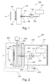
- Fig. 1 shows a deposition arrangement 100 for evaporation of alkali and alkaline earth metals, particularly lithium.
- a first chamber or tank 110 is provided for receiving the material to be deposited.
- the tank is provided such that the material to be evaporated in the arrangement, i.e. an alkali and alkaline earth metal, e.g. lithium, can be provided in tank 110 under a non-reactive atmosphere.
- the non-reactive atmosphere can be argon or another inert gas suitable to prevent reaction of the material to be evaporated, which is typically highly reactive.
- the tank 110 is configured to heat the material to a temperature above the melting point, for example 5°C to 100°C, for example 20°C to 60°C (e.g. 20°C or 40°C) above the melting point of the material to be deposited.
- the material to be deposited is transported towards the vapor distribution showerhead 112 or a respective nozzle via the valve 130 in a liquid state.
- the conduit or conduits 120 and/or the valve 130 can be configured to be heated such that the liquid alkali or alkaline earth metal can be provided to an evaporation zone, e.g. in or close to the showerhead.
- the deposition system for the alkali and alkaline earth metal has one or more outlets for directing the vapor of the alkali and alkaline earth metal towards a substrate for deposition of the alkali and alkaline earth metal on the substrate.
- the outlet can be one or more openings or one or more nozzles, which can e.g. be provided in a showerhead or another vapor distribution system.
- the evaporator arrangement can include a nozzle for guiding the vapor towards the substrate. As shown in FIG. 1 , the arrangement can include a vapor distribution showerhead 112, e.g. a linear vapor distribution showerhead 112 having a plurality of nozzles 116.
- the precursor reservoir is a single chamber component where the Li metal both melts and evaporates to reach a showerhead in the deposition chamber.
- the evaporated material i.e. the vapor
- the region for the material to be evaporated e.g. lithium
- the first chamber such as the tank 110, liquefies the alkali or alkaline earth metal
- the liquefied alkali or alkaline earth metal is guided through valve 130, and a further area, zone or chamber downstream of the valve 130 evaporates the alkali or alkaline earth metal.
- the liquid material is guided in the material feed system from the first chamber 110 through conduits 120 and through the valve.
- the liquid material is guided from the valve 130 through conduit 120 into the showerhead 112.
- a heating unit 118 can be provided adjacent to the showerhead 112 to heat the material to higher temperatures before providing the liquid material in the evaporation zone 114.
- the material is evaporated in the evaporation zone 114.
- the material is distributed in the showerhead 112 and directed through nozzles 116 towards the substrate 4.
- the valve can be a control-valve for controlling or adjusting the flow rate of the liquid material.
- the valve can separate the liquefying zone and the evaporation zone.
- the first chamber or tank 110 stores the solid lithium metal. It is used to melt and/or liquefy the solid lithium metal. The melted or liquefied lithium metal flows, i.e. in a liquid state, into a second chamber or another evaporation zone.
- lithium metal Even though reference is sometimes made to lithium metal herein, it is understood that also other alkali or alkaline earth metals, which are highly reactive, can benefit from the arrangements described herein.
- alkali metals can be used, and the arrangements and apparatuses can be configured for alkali metals. Accordingly, also sodium, potassium, rubidium or cesium, can be evaporated for desired applications. Yet, utilization of and configuration for lithium is a typical embodiment. Lithium is even more reactive as compared to some other alkali or alkaline earth metals and can be used for a plurality of applications.
- the tank 110 or a respective chamber for feeding the material to be evaporated into the arrangement, apparatus or system can be replaceable and/or re-fillable.
- it can be replaceable and/or re-filled while the material to be evaporated is under a protective atmosphere such as argon, another inert gas, and/or under vacuum conditions.
- the first chamber can be an open chamber or a closed chamber.
- the opening of an open chamber can be used to re-fill material to be melted and evaporated in the deposition arrangement.
- a closed chamber can be provided with a lid configured for opening the chamber. Material to be melted and evaporated can be re-filled when the lid is open. Chambers having a lid allow more easily for a protective atmosphere, as an overpressure such as a pressure of atmospheric pressure plus 50 mbar to a pressure of atmospheric pressure plus 300 mbar can be provided in the material feed system of the deposition arrangement.
- the material feed system includes the portion of the deposition arrangement in which the liquid materials is fed towards the evaporation zone.
- the material feed system can include a first chamber, conduits and a valve. Yet, further it can include one or more purge gas conduits, a supply system for protective gas and/or elements to control the temperature of the material feed system.
- the further chamber or evaporation zone for evaporation of the material can be the nozzle for directing the vapor towards a substrate, the vapor distribution showerhead 112, a further chamber or evaporation zone 114, or a respective area, which is provided between the valve 130 and the vapor distribution showerhead 112 or which is provided in the vapor distribution showerhead
- the evaporation zone 114 can be a chamber, a crucible, a boat, or a surface, configured to provide the energy for evaporation.
- the zone or surface has a sufficient surface contact area, e.g. in the range of 1 cm 2 to 50 cm 2 , for example 1 cm 2 to 10 cm 2 , to provide sufficient energy to evaporate the material.
- the surface area can be provided by a fin-structure where on or more fins protrude from a base, by a cup-like like shape, or by a spoon-like shape.
- a showerhead can be understood herein, includes an enclosure having openings such that the pressure in the showerhead is higher than outside of the showerhead, for example at least one order of magnitude.
- FIG. 1 shows a schematic cross-sectional view of an evaporation arrangement 100, wherein a tank 110 is connected with a conduit 120 to the valve 130, which is further connected with a further conduit 120 with the evaporation showerhead 112.
- the material e.g. lithium
- the material is liquefied in the tank 110, is guided in liquid form through the valve 130 and is evaporated after the valve 130 to be guided via the outlet, e.g. nozzles 116, towards substrate 4.
- the substrate or substrates can be processed vertically, i.e. the linear gas distribution showerhead 112 is arranged vertically within a chamber and a substrate positioner holds the substrate 4 in a vertical processing position, as exemplarily shown in FIG. 1 .
- the linear gas distribution showerhead 112 is arranged vertically within a chamber and a substrate positioner holds the substrate 4 in a vertical processing position, as exemplarily shown in FIG. 1 .
- a material feed system with liquid material in addition to the evaporation zone allows for an arbitrary orientation of the showerhead, such that deposition arrangements according to embodiments described herein, can be more flexibly used as compared to other deposition sources.
- top down evaporation can be used, e.g. in semiconductor processing
- bottom up evaporation can be used, e.g. for flexible substrates, or any other orientation can be used.
- This flexibility in directionality in deposition comes from having an independent reservoir and deposition zone. Accordingly, an another advantage as compared to crucible deposition can optionally be provided.
- showerhead shown in FIG. 1 is a linear showerhead
- other shapes of showerheads are also within the scope of the invention. What shape the showerhead should have will depend on both, the type of chamber and the shape of the substrate. For example, a point source, i.e. a single nozzle, or a circular showerhead may be selected for a chamber that processes circular substrates, such as when processing semiconductor wafers. Whereas a rectangular showerhead may be selected for processing large rectangular substrates, batch processes may also make those types of showerhead shapes more preferable. For continuous inline processing of large size rectangular or square substrates, a linear showerhead may be selected to better control the distribution of process gases over the substrate as the substrate passes by the showerhead.
- linear vapor distribution showerheads can be used, particularly for in-line or dynamic processing apparatus. Circular, rectangular or two or more linear vapor distribution showerheads can be used for static deposition processes of substrates of various shape and size.
- large area substrates or respective carriers wherein the carriers have one or more substrates, may have a size of at least 0.67 m 2 .
- the size can be about 0.67m 2 (0.73x0.92m - Gen 4.5) to about 8 m 2 , more typically about 2 m 2 to about 9 m 2 or even up to 12 m 2 .
- the substrates or carriers for which the structures, apparatuses, such as cathode assemblies, and methods according to embodiments described herein are provided, are large area substrates as described herein.
- a large area substrate or carrier can be GEN 4.5, which corresponds to about 0.67 m 2 substrates (0.73x0.92m), GEN 5, which corresponds to about 1.4 m 2 substrates (1.1 m x 1.3 m), GEN 7.5, which corresponds to about 4.29 m 2 substrates (1.95 m x 2.2 m), GEN 8.5, which corresponds to about 5.7m 2 substrates (2.2 m x 2.5 m), or even GEN 10, which corresponds to about 8.7 m 2 substrates (2.85 m x 3.05 m). Even larger generations such as GEN 11 and GEN 12 and corresponding substrate areas can similarly be implemented.
- a substrate carrier can be equipped with one or with several wafers.
- the length of the vapor distribution showerhead e.g. a vaporizer tube, can be adjusted to achieve the uniform coating on a large area substrate, having a substrate height of h, or of all substrates placed in a carrier.
- flexible substrates of synthetic material or metal can also be processed with embodiments described herein.
- a substrate positioner, a substrate support or a substrate transport system can be provided and configured to position and/or move the substrate in and through a procession region.
- Embodiments described herein provide an improved alkali metal, e.g. lithium, deposition system and source technology for creating thin and uniform films at high deposition rates and with reduced manufacturing cost.
- the deposition sources, arrangements, apparatuses, systems and methods can be applied in many fields that require uniform deposition of alkali metals, such as Li.
- This can be electrochemical devices which use lithium as the charge carrying element. Examples of such electrochemical devices include electrochromic windows and devices and thin film solid state batteries.
- Embodiments described herein significantly reduce the cost and manufacturability of existing solutions for depositing alkali metals, e.g. Li metal.
- FIG. 2 shows a schematic cross-sectional view of a deposition apparatus 200 with a deposition arrangement 100.
- the first chamber or tank 110 into which the material to be evaporated, e.g. lithium, is provided in an enclosure 210.
- the enclosure can be insulated.
- a temperature controlled environment can be provided for the first chamber and the valve as well as the conduits 120.
- the temperature can be controlled to be from 185°C to 285°C, e.g. about 230°C or 200°C.
- other temperatures could be provided and adjusted according to the melting point, e.g.
- the temperature for liquefying the materials can be provided from 5°C to 100°C, e.g. 50°C above the melting point of the material to be deposited on the substrate.
- one or more of the elements in the enclosure 210 can be individually heated and/or the interior of the enclosure can be heated as a whole.
- insulation as indicated by the wall 211 can be provided to reduce loss of heating energy.
- individual elements in the enclosure 210 can be insulated separately (not shown).
- the material feed system and particularly the valve and the conduits are configured to provide an essentially constant flow rate of the liquid lithium.
- the diameter of the conduits should be sufficiently small to result in an essentially constant flow rate towards the evaporation zone.
- the conduits can have a diameter of 1 mm 2 to 10 mm 2 .
- the diameter and desired flow rate can thereby also depend on the size of the showerhead and the respective processing zone, such that deposition arrangement for larger substrate may have larger conduit diameters as compared to deposition arrangements for smaller substrates.
- the deposition arrangement can be easily and fast switched on and off. Therefore, no shutter between the evaporation zone and the substrate is required.
- a showerhead particularly for large area substrates or large area carriers, can be provided with one or more material feed systems.
- a first chamber, conduits, a control valve, and an evaporation zone can be provided for each of the one or more material feed systems.
- Each material feed system can be provided at a desired position of the vapor distribution showerhead for providing the vapor of the material in the vapor distribution showerhead.
- two or more material feed systems can be provided to feed the same material into the vapor distribution showerhead in order to increase the deposition rate.
- valve 130 is connected to tank 110 via conduit 120 and with the vapor distribution showerhead by further conduit 120.
- the valve can be positioned adjacent the tank 110, adjacent the showerhead, or adjacent a further chamber for evaporation of the alkali metal, such that the number of conduits can be reduced.
- typically the valve will be located at some distance to an evaporation zone in order to reduce impact of the evaporation temperature on the valve.
- the conduits 120 as shown in the figures described herein, are exemplary.
- One or more conduits can be arranged to have the first chamber configured to melt and/or liquefy the material, the valve configured to control the material flow of the liquid material, the evaporation zone and the vapor distribution showerhead to be connected for fluid communication.
- a vacuum feed-through 218 is provided for the conduit to feed the metal, e.g. the liquid metal, into the vacuum chamber 220.
- the feed-through 218 can provide for thermal insulation between the lower temperatures in the enclosure 210 and the higher evaporation zone temperatures and/or for vacuum separation between the enclosure 210 and vacuum chamber 220.
- the vacuum chamber 220 is configured for depositing the metal on the substrate 4.
- the vapor distribution showerhead 112 is heated to vaporize the liquid lithium as indicated by evaporation zone 214.
- the liquid material is guided into the vapor distribution showerhead 112.
- the vapor distribution showerhead is heated by a heating unit, e.g. an inner heating tube 240.
- the inner heating tube can be an electric heating element, which is connected by connections 244 to power supply 242.
- FIG. 2 further shows an insulator 212 of the vapor distribution showerhead 112. The insulation results in the reduction of heating power and/or more uniform heating of the vapor distribution showerhead.
- the heating of the vapor distribution showerhead 112 can be provided by radiation heating, by heating lamps, e.g. IR heaters, inductive heating, electrical heating (as described above with respect to FIG. 2 ) and combinations thereof.
- the outlets or nozzles can also be provided as openings in the vapor distribution showerhead.
- the arrangement of openings or nozzles can be for example one or more lines of openings or nozzles.
- the openings or nozzles can be distributed along and within a rectangular shape.
- the openings or nozzles can be distributed along and within a circular shape.
- the openings or nozzles can be distributed such that the deposition of the vapor on the substrate 4 is uniform.
- the openings or nozzles can be at least partly uniformly distributed along one of the above described shapes.
- the density of openings or nozzles can be varied in some regions of the vapor distribution showerhead.
- a deposition rate measurement device 235 can be provided in the vacuum chamber 220. Thereby, the deposition rate of the lithium or another alkali metal on the substrate can be monitored.
- one or more oscillating crystals can be utilized for thickness measurement.
- optical measurement methods within the showerhead or at further measurement sections or openings of the showerhead can be utilized to determine the deposition rate.
- a pressure measurement inside the showerhead, a thickness measurement of the layer deposited on the substrate, e.g. a conductivity measurement such as an Eddy current measurement of the layer can be conducted to determine the deposition rate.
- the signal relating to the deposition rate can be utilized for control of the control valve.
- a signal corresponding to the measurement result of the deposition rate measurement device 235 can be fed to a controller 230, which controls the valve 130 depending on the signal received from the deposition rate measurement device 235.
- a controller 230 which controls the valve 130 depending on the signal received from the deposition rate measurement device 235.
- PID controller proportional-integral-derivative controller
- the PID controller receives the signal via signal line 232 and further receives and/or stores a nominal layer thickness value or another value correlating to a desired deposition rate.
- a feedback controller is provided for controlling the valve 130. Thereby, a closed loop control of the flow rate of liquid material flowing through the valve can be provided. Accordingly, simplified control of the deposition rate and/or of the deposition uniformity can be provided.
- the valve 130 can be a control valve, i.e. a valve to control the flow rate through the valve.
- the control valve can be configured to control the flow rate with a precision of ⁇ 50 g/h or below, such as ⁇ 0.1 g/h to 5 g/h.
- the control of deposition rate is simplified and more stable. Due the control of the flow rate of liquid material through the valve, there is no more need to control the deposition by a chamber temperature in the chamber wherein the material is melted and evaporated. Such a chamber temperature control is difficult because although the temperature may be stable, the evaporation rate may be different over the life of the reservoir content. This is because the evaporation rate also depends on the "surface area" of the metallic Li, which is in contact with the heated chamber, which may change over the life of the reservoir as volume ratio (and thus the surface area ratio) of the metallic Li vs. non-metallic Li compounds (reacted or oxidized, higher melting phases of Li) will likely change.
- Embodiments described herein control the deposition rate with the amount of liquid Li flowing through the valve (e.g., mass flow controllers), which will fully evaporate in the "flash evaporation chamber", i.e. the vapor distribution showerhead or another chamber between the valve and the vapor distribution showerhead.
- a full evaporation of the Li can be assured as only the metallic Li melts in the first chamber (by keeping temperature above Li melting temperature but below melting temperature of reacted Li compounds) to flow into the second flash evaporation chamber.
- the temperature in the evaporation chamber or evaporation zone can be 600°C or above, e.g. 800°C or above such as 800°C to 1000°C.
- the valve is configured and/or arranged such that liquid alkali metal, .e.g. liquid metallic lithium, flows through the valve.
- liquid alkali metal .e.g. liquid metallic lithium
- the hardware requirements are reduced, specifically for the valve that separates the source, e.g. the tank 110, and the evaporation zone or second chamber, e.g. the vapor distribution showerhead 112.
- the valve For one chamber evaporators, wherein the material is melted and vaporized in one chamber, a valve must withstand temperatures in the 600°C to 800°C range to keep the evaporated Li metal vapors from condensing and clogging up the path.
- valve, conduits, and/or other mass flow controllers only need to withstand temperatures of about 350°C or even below. Thereby, it should be considered that corrosion of materials due to exposure to lithium will be higher for higher temperatures of liquid or vaporized lithium. Accordingly, providing an extended group of components, which is only in contact with liquid lithium as compared to lithium vapor, reduces corrosion in the overall system.
- a vapor distribution chamber wherein the precursor reservoir design is configured for melting or liquefying the material.
- the flow of the material or precursor will be controlled by the valve, e.g., a micro-valve.
- a second chamber or zone is used to evaporate, e.g., flash evaporate, the liquid alkali metal, e.g., lithium, which flows into the second chamber or zone through the valve.
- the deposition rate can, thus, be controlled by the flow through said valve.
- the deposition arrangement for evaporation of alkali or alkaline earth metals typically, metallic lithium
- apparatuses including such deposition arrangements, and methods of operating thereof can be utilized for processes where metallic lithium deposition (or other alkali metals) is desired.
- this can be electrochemical devices, such as electrochromic windows and thin film batteries, Li deposition during OLED device fabrication, etc.
- FIG. 3 shows a vapor feed system 300 for a processing chamber 320, such as a vacuum chamber. Only the chamber wall 2 of the processing chamber 320 is shown in this figure.
- the vapor feed system 300 comprises a vertically oriented linear gas distribution showerhead 312, opposite of which a substrate 4 is disposed.
- the linear gas distribution showerhead 312 is provided with several gas passageways and is connected with gas conduit or inlet tube 305, which can e.g. be directed at right angles to the linear gas distribution showerhead 312.
- a material feed system including a tank 110, a control valve 130 and conduits 120 is provided.
- another valve a shut-off valve, not shown in FIG. 3
- a shut-off valve for closing and opening the material flow from the tank 110, i.e. a first chamber, to the control valve can be included upstream of the valve.
- a shut-off valve for closing and opening the material flow from the tank 110, i.e. a first chamber, to the control valve can be included upstream of the valve.
- a shut-off valve for closing and opening the material flow from the tank 110, i.e. a first chamber, to the control valve can be included upstream of the valve.
- FIG. 3 also illustrates a wall 6 of the enclosure adjacent to the vacuum chamber for deposition.
- the enclosure can, for example, be a glove box 40, which encompasses the chamber or tank 110, the valve 130 and the conduits 120.
- the tank 110 can be replaced, exchanged or filled with new lithium under protective gas or under another protective atmosphere.
- a protective gas for example, argon can be used.
- the conduits 120 and the first chamber, e.g. tank 110 can be heated by heating jacket 15. Yet, the enclosure for those elements can typically be heated entirely as described in more detail with respect to FIG. 6 .
- embodiments described herein typically further include a heat separation 14 such as an insulation between the enclosure in which the liquid material is guided and the evaporation zone, e.g. inlet tube 305 in FIG. 3 .
- the components of the material feed system and the deposition system are configured for lithium usage.
- Such materials can be selected from the group consisting of: stainless steel, particularly with a carbon content of 0.12% weight-% or smaller, molybdenum, tantalum, columbium, and combinations thereof.
- the valve can be provided having a valve body made of molybdenum or stainless steel with a carbon content of 0.112 weight-% or below in order to reduce corrosion with lithium or another alkali metal.
- the materials to be used for the chambers i.e. tank 110 and/or the showerhead 312 and the inlet tube 305, the valve 130 and the conduits 120 are configured to be exposed to the reactive material.
- the entire vapor feed system is comprised of a material that is inert relative to these reactive materials, such as lithium.
- FIG. 3 further shows another heating jacket 315, which provides heating for the evaporation zone.
- the linear vapor distribution showerhead and the inlet tube 305 are heated by the heating jacket 315.
- other heating means as described herein can additionally or alternatively be provided.
- the liquid material, which flows through valve 130 and conduit 120, is guided into the inlet tube 305, which is configured for temperatures of e.g. 800°C or above.
- the inlet tube and components downstream of the inlet tube are heated to temperatures of e.g. 800°C or above.
- the material entering the inlet tube 305 is evaporated instantaneously and the vapor is guided to the showerhead where it is guided through openings or nozzles to the substrate 4 for deposition of the vapor on the substrate.
- a linear vapor distribution showerhead for lithium (or other alkali metals) in combination with a liquid flow control enables uniform large area coating.
- the control of the flow can be provided by a control valve, which is controlled in dependence of a deposition rate monitor and/or a liquid flow meter.
- a linear vapor distribution showerhead can beneficially be utilized for inline deposition tools, where one or more substrates or one or more carriers with substrates disposed therein are transported past the showerhead.
- FIG. 4 illustrates yet further aspects of a deposition arrangement for evaporation of alkali metals or alkaline earth metals, and corresponding controls.
- a first chamber 410 provides for example liquid lithium 402.
- a temperature of about 200°C can be provided.
- metallic lithium which is to be deposited in chamber 220 on substrate 4 is liquid and can flow towards the chamber 220 in liquid form.
- Lithium compounds, such as non-metallic lithium compounds (e.g. lithium oxide), which may be generated due to the high reactivity of lithium, are not melted at such a temperature and will, thus, not flow towards the chamber 220. Accordingly, such lithium compounds can be excluded from the process.
- the first chamber for melting the lithium is under a pressure and ambient controlled atmosphere 411.
- a protective gas e.g. argon
- Valve 420 controls the argon environment at an over pressure of e.g. 100 to 300 mbar, such as 200 mbar.
- the manual valve 426 can be utilized for purging the tank with argon during maintenance or during refilling of the chamber 410.
- the pressure in the chamber is monitored by pressure gauge 422. Additionally or alternatively, a pressure gauge can also be provided towards the top of chamber 410 such that the pressure of the zone 411 can additionally or alternatively be measured.
- a liquid level sensor can be provided for the chamber 410 such that the liquid Li level in the chamber 410 can additionally be measured.
- the detected signal is provided by signal line 423 to control 424.
- Control 424 controls the valve 420 for adjusting the argon flow in the chamber 410.
- a controlled protective environment can be provided for the chamber 410.
- the chamber 410 is heated as described above and with heating elements according to embodiments described herein. Further, insulation (not shown in FIG. 4 ) for improved heat control can be provided.
- the liquid metallic lithium flows via conduit 120 towards valve 430.
- a heating jacket 15 can be provided for the conduit in order to avoid clogging of the conduit by solidifying of the lithium.
- the valve 430 has a valve housing 460.
- the liquid lithium flows through the valve housing.
- the amount of liquid lithium is controlled by actuator 462.
- the actuator 462 can be electrical. Other actuators like pneumatic or hydraulic might also be used. Yet, electrical actuation might be beneficial under conditions of elevated temperatures and controlled atmospheres within a deposition apparatus.
- Connector 431 provides an input of a signal line 434 from the controller 435.
- the controller 435 provides a control signal for the flow rate of the liquid lithium through valve 430.
- the controller can be any controller that allows control of the deposition rate of the lithium on the substrate 4 within the chamber 220.
- a feedback control which can for example utilize a PID controller, can be used. This is shown in FIG. 4 by signal line 432, which provides a signal correlating to the deposition rate in chamber 220 to the controller 435 and the signal line 433, which provides a nominal value as a comparison for the PID controller.
- the signal of a mass flow controller or another signal correlating to the deposition rate can be used as a control signal for the controller 435.
- valve 430 controls the flow rate through the valve housing 460 and the conduits 120. Downstream of valve 430 there is a further conduit 120 for fluid connection of the deposition chamber 220 with the valve 430 and in turn the first chamber 410.
- the liquid metallic lithium is flash evaporated before being deposited on the substrate.
- an evaporation zone or evaporation chamber is provided in the chamber 220, which can be at a temperature of 600°C or above, or even 800°C or above.
- an evaporation zone or evaporation chamber can also be provided between the valve and the chamber 220. Yet, it should be considered that evaporation close to a showerhead or even within a showerhead reduces the elements to be maintained at vapor temperatures (e.g. > 600°C) during operation.
- FIG. 5 shows a flow chart 500 illustrating embodiments of methods of evaporating a material comprising an alkali metal or alkaline earth metal, particularly metallic lithium.
- the method includes liquefying the material in a first chamber as indicated by reference numeral 502.
- the liquefied material is guided from the first chamber through a control valve to a second chamber.
- the material is evaporated in the second chamber and the vapor of the material is directed onto a substrate in step 508.
- the evaporation step 506 can be provided by flash evaporation particularly at temperatures of 600°C or above.
- the temperature can be 800°C or above.
- the liquefied material is maintained at a temperature of 5°C to 30°C, to 60°C or 100°C above the melting point of the material to be deposited, e.g. 190°C to 290°C for metallic lithium.
- components of the deposition arrangement and deposition apparatus, which are provided upstream of the second chamber for evaporation of the material can have a limited resistance to high temperatures. That is, these components need to withstand only temperatures at which the lithium or another material, according to embodiments described herein, is liquid. This can be particularly beneficial as these materials are also highly reactive.
- a closed loop control for control of the valve for adjusting the flow rate of the liquefied material through the valve, can be provided, as further illustrated in step 510.
- the closed loop control of the valve can be simplified as compared to common lithium evaporators as merely a flow rate of liquid material through the valve needs to be controlled.
- the signal for feedback control can thereby be selected from the group consisting of: a deposition rate monitor in a vacuum chamber for vapor deposition, a flow meter such as a mass flow controller, in the system for guiding the liquefied material to the second chamber, a layer thickness measurement, such as an Eddy current measurement, a vapor pressure measurement in the showerhead, and combinations thereof.
- the control of deposition rate is simplified and more stable. Due to the control of the flow rate of liquid material through the valve, there is no more need to control the deposition by a chamber temperature in the chamber wherein the material is melted and evaporated. Such a chamber temperature control is difficult because although the temperature may be stable, the evaporation rate may be different over the life of the reservoir content. This is because the evaporation rate also depends on the "surface area" of the metallic Li, which is in contact with the heated chamber, which may change over the life of the reservoir as volume ratio (and thus the surface area ratio) of the metallic Li vs. non-metallic Li compounds (reacted or oxidized, higher melting phases of Li) will likely change.
- Embodiments described herein control the deposition rate with the amount of liquid Li flowing through the valve (e.g., mass flow controllers), which will fully evaporate in the "flash evaporation chamber", i.e. the vapor distribution showerhead or another chamber between the valve and the vapor distribution showerhead.
- a full evaporation of the Li can be assured as only the metallic Li melts in the first chamber (by keeping the temperature above Li melting temperature but below melting temperature of reacted Li compounds) to flow into the second flash evaporation chamber.
- the second chamber, zone or area, in which the liquid material is evaporated can be provided by various components.
- the second chamber, zone or area is provided downstream of the valve for control of the flow of liquid material, i.e. the valve is between the second chamber, zone or area and the chamber for liquefying the material.
- the second chamber, zone or area can be provided by a separate chamber, can be provided by the evaporation nozzle or vapor distribution showerhead, can be provided by surface in or adjacent to the vapor distribution showerhead with a sufficient surface contact area, e.g.
- the second chamber, zone or area can be provided such that there is an increase in temperature, typically a sudden increase in temperature for flash evaporation, on the pathway from the control valve (see, e.g. valves 130 and 430) to the vapor distribution nozzle or showerhead.
- the control valve see, e.g. valves 130 and 430
- all liquid material is evaporated and the control of the flow rate of the liquid material also controls the deposition rate.
- valves 130 and 430 that separates the source for the material and the second chamber, zone or area for evaporation.
- the valve For common single chamber systems, where lithium is melted and evaporated in a chamber upstream of a valve, the valve must withstand temperatures in the 600°C to 800°C range to keep the evaporated Li metal vapor from condensing and clogging up the path.
- the valve, and/or mass flow controller, as well as conduits providing a fluid communication between the material source and the second chamber, zone or area need to withstand likely at most 350°C.
- FIG. 6 shows a schematic cross-sectional view of portions of a deposition apparatus with a deposition arrangement 600.
- the first chamber or tank 110 into which the material to be evaporated, e.g. lithium, is provided in an enclosure 650.
- the enclosure can be insulated.
- a temperature controlled environment can be provided for the first chamber and the valve body 460 as well as the conduits 120.
- the temperature can be controlled to be from 185°C to 250°C, e.g. about 200°C.
- the temperature for liquefying the materials can be provided from 5°C to 100°C above the melting point of the material to be deposited on the substrate.
- the first chamber 110 has a flange 680, which can be exposed by opening the housing 610.
- the flange 680 can be connected to a flange 682 of a container 684 for refilling of material to be provided in the deposition arrangement 600.
- Connecting the container 684 with the first chamber or tank 110 is indicated by arrow 685.
- the procedure of refilling can be provided under a protective atmosphere, e.g. an argon atmosphere. Therefore, a connection of a glove box or other suitable ways to separate the area for refilling from normal atmosphere can be used.
- the first chamber can be provided entirely or partly with a heating system 615 to melt the material in the heated portion of the first chamber.
- the first chamber 110 is in fluid communication with the control valve 460.
- the fluid communication is provided by conduit 120.
- the vapor distribution showerhead 112 is provided in fluid communication with the valve 460.
- heating of the first chamber can also be provided, as described above, by the heating of the enclosure 650.
- gas circulation unit such as fan 620 is provided, which can be controlled by controller 622.
- controller 622 can be provided outside of the housing 610.
- the fan 620 allows for gas circulation inside the enclosure 650. Thereby, a uniform atmosphere can be provided inside the enclosure 650.
- the enclosure 650 is at atmospheric pressure and at a temperature slightly above the melting point of the material to be evaporated, e.g. 200°C.
- the gas in the enclosure 650 can be air, as the reactive material is inside the material feed and regulation system, which is under a protective atmosphere as described above.
- a protective gas such as argon, can also be provided in the enclosure 650 to even better avoid contact of reactive gases with the material to be melted.
- the material feed system provided by the first chamber, the one or more conduits and the valve can further include a purge valve 640 and a purge conduit 642.
- the purge conduit 642 and, thus, the purge valve 640 is connected with e.g. the portion of the flange 680 facing the first chamber 110.
- the conduit can additionally or alternatively be provided at the first chamber or at the conduit.
- the conduit from the tank to the valve can be connected to a purge conduit.
- the purge conduit can, according to yet further modifications, also be provided as a purge conduit arrangement with a plurality of purge conduits connected to the material feed system.
- the purge conduit is provided at least at an upstream end of the material feed system.
- the purge valve can be connected with a source of hot argon.
- the material feed system can be flushed with hot argon.
- the argon can be heated by guided argon tubes around the tank with liquid lithium.
- the material feed system can be purged with argon to avoid having oxygen and/or moisture in the system before lithium or another alkali-metal is provided in the material feed system.
- valve 130 is connected to tank 110 via conduit 120 and with the vapor distribution showerhead by further conduit 120.
- a vacuum feed-through 218 is provided for the conduit to feed the metal, e.g. the liquid metal, into the chamber portion housing the showerhead 112.
- the conduit portion downstream of the feed-through from the enclosure 650 to the chamber portion housing the showerhead is heated by heating unit 618. Thereby, the portions of the deposition arrangement downstream of the enclosure 650 can be heated to higher temperatures as compared to the portions of the deposition arrangement disposed in the enclosure 650.
- the chamber portion housing the showerhead can be connected to a vacuum chamber via flange 604.
- a vacuum chamber via flange 604.
- an evaporation surface is heated to vaporize the liquid lithium as indicated by evaporation zone 114.
- the material evaporated in the evaporation zone 114 is guided into and/or distributed in the vapor distribution showerhead 112.
- the evaporation zone 114 can be a chamber, crucible, boat, or surface, configured to provide the energy for evaporation.
- the zone or surface has a sufficient surface contact area, e.g. in the range of 1 cm 2 to 10 cm 2 , to provide sufficient energy to evaporate the material.
- the heating unit 618 which is mentioned above, can be configured to continuously increase the temperature of the liquid material towards the evaporation zone 114.
- the vapor distribution showerhead is heated by a heating unit, e.g. an inner heating tube 240, wherein further details, aspects, features and additional or alternative implementation of a heating unit are described in other embodiments described herein.
- a heating unit e.g. an inner heating tube 240
- the showerhead is provided with an insulator 212 for thermal insulation of the vapor distribution showerhead 112.
- the outlets, e.g. nozzles 116, provided at the vapor distribution showerhead guide or direct the vapor of e.g. lithium towards a substrate.
- the outlets or nozzles can be provided as described with respect to other embodiments referred to herein.
- the valve 460 is configured and/or arranged such that liquid alkali metal, .e.g. liquid metallic lithium, flows through the valve.
- liquid alkali metal .e.g. liquid metallic lithium
- the control valve 460 can be provided with a separate heating element 415 and optionally also with a separate thermal insulator and control circuit of the temperature of the valve. Thereby, temperature variations of the temperature of the control valve can be reduced. Accordingly, flow rate control of the liquid material can be improved.
- FIG. 7 shows an alternative solution of a first chamber 110, which can be implemented in any of the deposition arrangements described herein.
- the first chamber or tank 110 includes a first chamber portion 712.
- the first chamber portion 712 can be filled with solid material through flange 680.
- the first chamber portion 712 is connected to a second chamber portion 710.
- the material is melted in the second chamber portion 710. Therefore, for example heating elements 615 can be provided.
- heating elements 615 can be provided.
- electrical heaters can be used. Additionally, or alternatively radiation heaters could be used.
- the material melted ion the second chamber portion 120 flows in liquid form in conduit 120, i.e. through the material feed system as described herein.
- the first chamber portion 712 can be provided with an actuator for transporting material towards and into the second chamber 710.
- a feed screw can be provided in the first chamber portion.
- the first chamber portion and the second chamber portion can also be provided by two adjacent spaces within the same chamber.
- the material can also be melted in the first chamber portion 712 and optionally a valve can be provided between the first chamber portion and the second chamber portion. Accordingly, by providing a first chamber portion or a first chamber and a second chamber portion or a second chamber, feeding of new material can be better controlled such that the temperature of the melting zone does not drop suddenly on insertion of solid material. Particularly, the temperature in the second chamber portion can be controlled to be more stable. While the foregoing is directed to embodiments of the invention, other and further embodiments of the invention may be devised without departing from the basic scope thereof, and the scope thereof is determined by the claims that follow.
Landscapes
- Chemical & Material Sciences (AREA)
- Chemical Kinetics & Catalysis (AREA)
- Engineering & Computer Science (AREA)
- Materials Engineering (AREA)
- Mechanical Engineering (AREA)
- Metallurgy (AREA)
- Organic Chemistry (AREA)
- General Chemical & Material Sciences (AREA)
- Electrochemistry (AREA)
- Battery Electrode And Active Subsutance (AREA)
- Physical Vapour Deposition (AREA)
Abstract
Description
- Embodiments of the present invention relate to deposition and evaporation of alkali metals or alkaline earth metals, such as lithium. Embodiments of the present invention particularly relate to evaporation arrangements, deposition apparatuses, and methods of operation thereof for control of vaporized material. Specifically, they relate to a depositing arrangement for evaporation of a material comprising an alkali metal or alkaline earth metal and for deposition of the material on a substrate, a deposition apparatus for evaporation of a material comprising an alkali metal or alkaline earth metal and for deposition of the material on a substrate, and a method of evaporating a material comprising an alkali metal or alkaline earth metal, particularly metallic lithium.
- Modern thin film lithium batteries are, as a rule, produced in a vacuum chamber, wherein a substrate is provided with several layers, including a lithium layer. The lithium layer is formed, for example, through the deposition of lithium in a vapor state on the substrate. Since lithium is highly reactive, a plurality of measures needs to be addressed to operate and maintain such deposition systems. For example, exposure to air ambient's oxidizing vapors, in particular H2O, and contact with personnel after opening the vacuum chamber should be minimized.
- Further, vaporization with high deposition rates and increased uniformity is desired. Many types of thin film deposition systems have been deployed in the past. And, for alkali and/or alkaline earth metals, some typical arrangements of thin film deposition systems have been applied. However, these typical arrangements are not so amenable to high volume and low cost manufacturing because the methods have serious challenges in managing the high reactivity of the materials, while scaling to high volume production. This presents serious challenges in producing uniformly deposited pure Li. As is well known, these types of materials, especially Li, can easily be oxidized in reaction with ambient surroundings, e.g., gases, materials, etc. Thereby, lithium is of particular interest since it is suitable for the production of higher energy density batteries and accumulators.
- Common deposition systems for lithium, and other alkali metals or alkaline earth metals, respectively, utilize sputtering sources or conventional evaporation sources and methods of operating thereof. Sputtering methods for lithium are challenging, particular with respect to costs and manufacturability, in light of the reactivity of Li. The high reactivity at first influences the manufacturing of the target, which is a necessary component for sputtering, and secondly influences the handling of the resulting targets. Thereby, shipment, installation, preventive maintenance, etc., is more difficult as compared to non-reactive targets as the target material needs to be protected from reaction with ambient air. Another challenge comes from disposing of the spent material on the target as target utilization typically is not 100%. Accordingly, a user needs to neutralize or react the residual materials for safe disposal. Yet further and more importantly, since lithium's melting point is relatively low, at 183°C, the deposition rate can also be limited as the melting point limits against a high power density sputtering regime, a more amenable regime for high volume and lower cost manufacturing.
- Conventional evaporation methods for lithium, which could typically utilize point sources, are challenging because of complications to achieve necessary uniformity and manufacturability in scaling it up to high volume manufacturing. Thereby, the need to manage or supply the highly reactive Li metal to the evaporation source and the reactive vapor to the deposition chamber is challenging. However, this is necessary for high volume manufacturing and high uptime manufacturing.
- Some prior art alkali and alkaline earth metal deposition systems are known to have insufficient throughput and do not provide for sufficient ease of scalability for high throughput and large substrates. There is a need for alkali and alkaline earth metal deposition sources and systems, particularly lithium deposition sources and deposition arrangements that may be scaled to accommodate the increasing size of substrates and allow for high throughput deposition. Thereby, cost competitive manufacturing of devices such as thin film batteries and electrochromic windows is to be considered. Yet further, uniformity of deposition processes is a desire to be considered.
- In light of the above, a deposition arrangement, a deposition apparatus and a method of evaporating according to the claims and particularly the independent claims are provided. Further aspects, advantages, and features of the present invention are apparent from the dependent claims, the description, and the accompanying drawings.
- According to one embodiment, a depositing arrangement for evaporation of a material including an alkali metal or alkaline earth metal and for deposition of the material on a substrate is provided. The arrangement includes a first chamber configured for liquefying the material, a valve being in fluid communication with the first chamber, and being downstream of the first chamber, wherein the valve is configured for control of the flow rate of the liquefied material through the valve, an evaporation zone being in fluid communication with the valve, and being downstream of the valve, wherein the evaporation zone is configured for vaporizing the liquefied material, and one or more outlets for directing the vaporized material towards the substrate.
- According to another embodiment, a deposition apparatus for evaporation of a material including an alkali metal or alkaline earth metal and for deposition of the material on a substrate is provided. The apparatus includes a vacuum chamber for depositing the material on the substrate therein, and a deposition arrangement. The arrangement includes a first chamber configured for liquefying the material, a valve being in fluid communication with the first chamber, and being downstream of the first chamber, wherein the valve is configured for control of the flow rate of the liquefied material through the valve, an evaporation zone being in fluid communication with the valve, and being downstream of the valve, wherein the evaporation zone is configured for vaporizing the liquefied material, and one or more outlets for directing the vaporized material towards the substrate.
- According to a further embodiment, a method of evaporating a material comprising an alkali metal or alkaline earth metal, particularly metallic lithium is provided. The method includes liquefying the material in a first chamber, guiding the liquefied material from the first chamber through a control valve to a evaporation zone, evaporating the material in the evaporation zone, and directing the vapor of the material on a substrate.
- So that the manner in which the above recited features of the present invention can be understood in detail, a more particular description of the invention, briefly summarized above, may be had by reference to embodiments. The accompanying drawings relate to embodiments of the invention and are described in the following:
- FIG. 1
- shows a schematic view of a deposition arrangement for evaporation of alkali metals or alkaline earth metals, such as lithium, according to embodiments described herein and includes a liquefying zone, a control valve for control of a flow rate and an evaporation zone downstream of the valve;
- FIG. 2
- shows a schematic view of another deposition arrangement and apparatus for evaporation of alkali metals or alkaline earth metals, such as lithium, according to further embodiments described herein and includes a liquefying zone, a control valve for control of a flow rate and an evaporation zone downstream of the valve;
- FIG. 3
- shows a schematic view of yet another deposition arrangement and an apparatus for evaporation of alkaline metals or alkaline earth metals, such as lithium, according to yet further embodiments described herein and includes a liquefying zone, a control valve for control of a flow rate and an evaporation zone downstream of the valve;
- FIG. 4
- shows a schematic view of a control scheme of a deposition arrangement for evaporation of alkali metals or alkaline earth metals, such as lithium, according to embodiments described herein and including a liquefying zone, a control valve for control of a flow rate and an evaporation zone downstream of the valve;
- FIG. 5
- shows a flow chart of an evaporation method according to embodiments described herein wherein the material is liquefied, a flow rate is controlled by a valve and downstream of the valve the material is evaporated;
- FIG. 6
- shows a schematic view of yet another deposition arrangement and an apparatus for evaporation of alkali metals or alkaline earth metals, such as lithium, according to yet further embodiments described herein; and
- FIG. 7
- shows a schematic view of a first chamber to be used in some embodiments of deposition arrangements according to embodiments described herein.
- Reference will now be made in detail to the various embodiments of the invention, one or more examples of which are illustrated in the figures. Within the following description of the drawings, the same reference numbers refer to same components. Generally, only the differences with respect to individual embodiments are described. Each example is provided by way of explanation of the invention and is not meant as a limitation of the invention. Further, features illustrated or described as part of one embodiment can be used on or in conjunction with other embodiments to yield yet a further embodiment. It is intended that the description includes such modifications and variations.
-
Fig. 1 shows adeposition arrangement 100 for evaporation of alkali and alkaline earth metals, particularly lithium. A first chamber ortank 110 is provided for receiving the material to be deposited. Typically, the tank is provided such that the material to be evaporated in the arrangement, i.e. an alkali and alkaline earth metal, e.g. lithium, can be provided intank 110 under a non-reactive atmosphere. For example, the non-reactive atmosphere can be argon or another inert gas suitable to prevent reaction of the material to be evaporated, which is typically highly reactive. - The
tank 110 is configured to heat the material to a temperature above the melting point, for example 5°C to 100°C, for example 20°C to 60°C (e.g. 20°C or 40°C) above the melting point of the material to be deposited. Thereby, the material to be deposited is transported towards thevapor distribution showerhead 112 or a respective nozzle via thevalve 130 in a liquid state. Accordingly, according to some embodiments, which can be combined with other embodiments described herein, the conduit orconduits 120 and/or thevalve 130 can be configured to be heated such that the liquid alkali or alkaline earth metal can be provided to an evaporation zone, e.g. in or close to the showerhead. - According to typical embodiments, the deposition system for the alkali and alkaline earth metal, e.g. lithium, has one or more outlets for directing the vapor of the alkali and alkaline earth metal towards a substrate for deposition of the alkali and alkaline earth metal on the substrate. The outlet can be one or more openings or one or more nozzles, which can e.g. be provided in a showerhead or another vapor distribution system. According to some embodiments, which can be combined with other embodiments described herein, the evaporator arrangement can include a nozzle for guiding the vapor towards the substrate. As shown in
FIG. 1 , the arrangement can include avapor distribution showerhead 112, e.g. a linearvapor distribution showerhead 112 having a plurality ofnozzles 116. - For existing lithium evaporators, the precursor reservoir is a single chamber component where the Li metal both melts and evaporates to reach a showerhead in the deposition chamber. Thereby, the evaporated material, i.e. the vapor, is guided through a single separation valve in the vapor state. As shown in
FIG. 1 , and according to embodiments described herein, the region for the material to be evaporated, e.g. lithium, is separated into two chambers, zones or areas. The first chamber, such as thetank 110, liquefies the alkali or alkaline earth metal, the liquefied alkali or alkaline earth metal is guided throughvalve 130, and a further area, zone or chamber downstream of thevalve 130 evaporates the alkali or alkaline earth metal. - As shown in
FIG. 1 , the liquid material is guided in the material feed system from thefirst chamber 110 throughconduits 120 and through the valve. Before entering thevapor distribution showerhead 112, the liquid material is guided from thevalve 130 throughconduit 120 into theshowerhead 112. Thereby, aheating unit 118 can be provided adjacent to theshowerhead 112 to heat the material to higher temperatures before providing the liquid material in theevaporation zone 114. The material is evaporated in theevaporation zone 114. The material is distributed in theshowerhead 112 and directed throughnozzles 116 towards thesubstrate 4. - According to some embodiments, which can be combined with other embodiments described herein, the valve can be a control-valve for controlling or adjusting the flow rate of the liquid material. The valve can separate the liquefying zone and the evaporation zone. The first chamber or
tank 110 stores the solid lithium metal. It is used to melt and/or liquefy the solid lithium metal. The melted or liquefied lithium metal flows, i.e. in a liquid state, into a second chamber or another evaporation zone. Even though reference is sometimes made to lithium metal herein, it is understood that also other alkali or alkaline earth metals, which are highly reactive, can benefit from the arrangements described herein. Particularly alkali metals can be used, and the arrangements and apparatuses can be configured for alkali metals. Accordingly, also sodium, potassium, rubidium or cesium, can be evaporated for desired applications. Yet, utilization of and configuration for lithium is a typical embodiment. Lithium is even more reactive as compared to some other alkali or alkaline earth metals and can be used for a plurality of applications. - In light of the above, and according to some embodiments, which can be combined with other embodiments described herein, the
tank 110 or a respective chamber for feeding the material to be evaporated into the arrangement, apparatus or system can be replaceable and/or re-fillable. Typically, it can be replaceable and/or re-filled while the material to be evaporated is under a protective atmosphere such as argon, another inert gas, and/or under vacuum conditions. - According to yet further embodiments, which can be combined with other embodiments described herein, the first chamber can be an open chamber or a closed chamber. Typically, the opening of an open chamber can be used to re-fill material to be melted and evaporated in the deposition arrangement. A closed chamber can be provided with a lid configured for opening the chamber. Material to be melted and evaporated can be re-filled when the lid is open. Chambers having a lid allow more easily for a protective atmosphere, as an overpressure such as a pressure of atmospheric pressure plus 50 mbar to a pressure of atmospheric pressure plus 300 mbar can be provided in the material feed system of the deposition arrangement.
- As described herein, the material feed system includes the portion of the deposition arrangement in which the liquid materials is fed towards the evaporation zone. Typically, the material feed system can include a first chamber, conduits and a valve. Yet, further it can include one or more purge gas conduits, a supply system for protective gas and/or elements to control the temperature of the material feed system.
- According to different embodiments described herein, which can be combined with other embodiments described herein, the further chamber or evaporation zone for evaporation of the material can be the nozzle for directing the vapor towards a substrate, the
vapor distribution showerhead 112, a further chamber orevaporation zone 114, or a respective area, which is provided between thevalve 130 and thevapor distribution showerhead 112 or which is provided in the vapor distribution showerhead - According to typical implementations, which can be combined with other embodiments described herein, the
evaporation zone 114 can be a chamber, a crucible, a boat, or a surface, configured to provide the energy for evaporation. Typically, the zone or surface has a sufficient surface contact area, e.g. in the range of 1 cm2 to 50 cm2, for example 1 cm2 to 10 cm2, to provide sufficient energy to evaporate the material. Thereby, the surface area can be provided by a fin-structure where on or more fins protrude from a base, by a cup-like like shape, or by a spoon-like shape. - According to some implementations, a showerhead can be understood herein, includes an enclosure having openings such that the pressure in the showerhead is higher than outside of the showerhead, for example at least one order of magnitude.
- By providing a linear
vapor distribution showerhead 112 uniformity of the deposition on thesubstrate 4 can be increased. However, it has to be considered that a plurality of nozzles also results in an increasing demand for a continuous and controlled flow of the material towards thevapor distribution showerhead 112, as well as the need to provide new material in thetank 110 upon usage of the material. Due to the ability to provide new material, e.g. by replacing the tank, a continuous or quasi-continuous operation of the evaporation arrangement, of an apparatus for evaporation having such an evaporation arrangement according to embodiments described herein, or of a system for evaporation having such an evaporation arrangement according to embodiments described herein, can be provided. - As described above,
FIG. 1 shows a schematic cross-sectional view of anevaporation arrangement 100, wherein atank 110 is connected with aconduit 120 to thevalve 130, which is further connected with afurther conduit 120 with theevaporation showerhead 112. The material, e.g. lithium, is liquefied in thetank 110, is guided in liquid form through thevalve 130 and is evaporated after thevalve 130 to be guided via the outlet,e.g. nozzles 116, towardssubstrate 4. - According to some embodiments, the substrate or substrates can be processed vertically, i.e. the linear
gas distribution showerhead 112 is arranged vertically within a chamber and a substrate positioner holds thesubstrate 4 in a vertical processing position, as exemplarily shown inFIG. 1 . One advantage of this arrangement is that any particles created during processing will fall towards the bottom of a chamber and not contaminate thesubstrate 4. - However, providing a material feed system with liquid material in addition to the evaporation zone allows for an arbitrary orientation of the showerhead, such that deposition arrangements according to embodiments described herein, can be more flexibly used as compared to other deposition sources. For example, top down evaporation can be used, e.g. in semiconductor processing, bottom up evaporation can be used, e.g. for flexible substrates, or any other orientation can be used. This flexibility in directionality in deposition comes from having an independent reservoir and deposition zone. Accordingly, an another advantage as compared to crucible deposition can optionally be provided.
- Although the showerhead shown in
FIG. 1 is a linear showerhead, other shapes of showerheads are also within the scope of the invention. What shape the showerhead should have will depend on both, the type of chamber and the shape of the substrate. For example, a point source, i.e. a single nozzle, or a circular showerhead may be selected for a chamber that processes circular substrates, such as when processing semiconductor wafers. Whereas a rectangular showerhead may be selected for processing large rectangular substrates, batch processes may also make those types of showerhead shapes more preferable. For continuous inline processing of large size rectangular or square substrates, a linear showerhead may be selected to better control the distribution of process gases over the substrate as the substrate passes by the showerhead. With respect to point source nozzles it should, however, be considered that challenges may result from managing multiple point sources to achieve uniform deposition on large area substrates. Accordingly, beneficially linear vapor distribution showerheads can be used, particularly for in-line or dynamic processing apparatus. Circular, rectangular or two or more linear vapor distribution showerheads can be used for static deposition processes of substrates of various shape and size. - According to some embodiments, which can be combined with other embodiments described herein, the embodiments described herein can be utilized for evaporation on large area substrates, e.g. for electrochromic windows or lithium battery manufacturing. According to some embodiments, large area substrates or respective carriers, wherein the carriers have one or more substrates, may have a size of at least 0.67 m2. Typically, the size can be about 0.67m2 (0.73x0.92m - Gen 4.5) to about 8 m2, more typically about 2 m2 to about 9 m2 or even up to 12 m2. Typically, the substrates or carriers, for which the structures, apparatuses, such as cathode assemblies, and methods according to embodiments described herein are provided, are large area substrates as described herein. For instance, a large area substrate or carrier can be GEN 4.5, which corresponds to about 0.67 m2 substrates (0.73x0.92m), GEN 5, which corresponds to about 1.4 m2 substrates (1.1 m x 1.3 m), GEN 7.5, which corresponds to about 4.29 m2 substrates (1.95 m x 2.2 m), GEN 8.5, which corresponds to about 5.7m2 substrates (2.2 m x 2.5 m), or even GEN 10, which corresponds to about 8.7 m2 substrates (2.85 m x 3.05 m). Even larger generations such as GEN 11 and GEN 12 and corresponding substrate areas can similarly be implemented.
- The herein described arrangements, apparatuses, systems, methods and processes can be utilized for the coating of glass substrates. However, using them, it is also possible to coat wafers, such as silicon wafers, of e.g. 200 mm or 300 mm diameter. For example, a substrate carrier can be equipped with one or with several wafers. The length of the vapor distribution showerhead, e.g. a vaporizer tube, can be adjusted to achieve the uniform coating on a large area substrate, having a substrate height of h, or of all substrates placed in a carrier. Yet further, flexible substrates of synthetic material or metal can also be processed with embodiments described herein. According to typical implementations, a substrate positioner, a substrate support or a substrate transport system can be provided and configured to position and/or move the substrate in and through a procession region.
- Embodiments described herein provide an improved alkali metal, e.g. lithium, deposition system and source technology for creating thin and uniform films at high deposition rates and with reduced manufacturing cost. The deposition sources, arrangements, apparatuses, systems and methods can be applied in many fields that require uniform deposition of alkali metals, such as Li. This can be electrochemical devices which use lithium as the charge carrying element. Examples of such electrochemical devices include electrochromic windows and devices and thin film solid state batteries. Embodiments described herein significantly reduce the cost and manufacturability of existing solutions for depositing alkali metals, e.g. Li metal.
-
FIG. 2 shows a schematic cross-sectional view of adeposition apparatus 200 with adeposition arrangement 100. Thereby,FIG. 2 illustrates one embodiment and can be used to describe yet further embodiments. The first chamber ortank 110, into which the material to be evaporated, e.g. lithium, is provided in anenclosure 210. For example, the enclosure can be insulated. Thereby, a temperature controlled environment can be provided for the first chamber and the valve as well as theconduits 120. According to typical embodiments, the temperature can be controlled to be from 185°C to 285°C, e.g. about 230°C or 200°C. For alkali metals or alkaline earth metals other than lithium, other temperatures could be provided and adjusted according to the melting point, e.g. to 63°C or above for potassium. According to typical embodiments, which can be combined with other embodiments described herein, the temperature for liquefying the materials can be provided from 5°C to 100°C, e.g. 50°C above the melting point of the material to be deposited on the substrate. - Upon heating of the material feed system including the
tank 110, theconduits 120, and thevalve 130, to or above the melting point of the respective alkali metal, the metal is melted or liquefied and flows through the conduits in a liquid form. According to typical embodiments, one or more of the elements in theenclosure 210 can be individually heated and/or the interior of the enclosure can be heated as a whole. Typically, insulation as indicated by thewall 211 can be provided to reduce loss of heating energy. Additionally or alternatively, individual elements in theenclosure 210 can be insulated separately (not shown). - According to typical embodiments, which can be combined with other embodiments described herein, the material feed system and particularly the valve and the conduits are configured to provide an essentially constant flow rate of the liquid lithium. Accordingly, the diameter of the conduits should be sufficiently small to result in an essentially constant flow rate towards the evaporation zone. Thereby, for example, the conduits can have a diameter of 1 mm2 to 10 mm2. The diameter and desired flow rate can thereby also depend on the size of the showerhead and the respective processing zone, such that deposition arrangement for larger substrate may have larger conduit diameters as compared to deposition arrangements for smaller substrates.
- In light of the fact that the amount of material in the comparable thin conduits is limited and that the temperatures in the liquid material feed system and that the evaporation zone can be maintained for interruption of the deposition process, the deposition arrangement can be easily and fast switched on and off. Therefore, no shutter between the evaporation zone and the substrate is required.
- According to yet further embodiments, which can be combined with other embodiments described herein, a showerhead, particularly for large area substrates or large area carriers, can be provided with one or more material feed systems. Thereby, a first chamber, conduits, a control valve, and an evaporation zone can be provided for each of the one or more material feed systems. Each material feed system can be provided at a desired position of the vapor distribution showerhead for providing the vapor of the material in the vapor distribution showerhead. For example, two or more material feed systems can be provided to feed the same material into the vapor distribution showerhead in order to increase the deposition rate. Yet further, it is also possible to feed more than one kind of material in the vapor distribution showerhead in order to deposit a compound of the different materials provided in the different material feed systems.
- As shown in
FIG. 2 ,valve 130 is connected totank 110 viaconduit 120 and with the vapor distribution showerhead byfurther conduit 120. According to yet further embodiments, described herein, the valve can be positioned adjacent thetank 110, adjacent the showerhead, or adjacent a further chamber for evaporation of the alkali metal, such that the number of conduits can be reduced. However, typically the valve will be located at some distance to an evaporation zone in order to reduce impact of the evaporation temperature on the valve. Theconduits 120, as shown in the figures described herein, are exemplary. One or more conduits can be arranged to have the first chamber configured to melt and/or liquefy the material, the valve configured to control the material flow of the liquid material, the evaporation zone and the vapor distribution showerhead to be connected for fluid communication. - As shown in
FIG. 2 and according to some embodiments described herein, a vacuum feed-through 218 is provided for the conduit to feed the metal, e.g. the liquid metal, into thevacuum chamber 220. The feed-through 218 can provide for thermal insulation between the lower temperatures in theenclosure 210 and the higher evaporation zone temperatures and/or for vacuum separation between theenclosure 210 andvacuum chamber 220. Thevacuum chamber 220 is configured for depositing the metal on thesubstrate 4. As shown inFIG. 2 , thevapor distribution showerhead 112 is heated to vaporize the liquid lithium as indicated byevaporation zone 214. The liquid material is guided into thevapor distribution showerhead 112. The vapor distribution showerhead is heated by a heating unit, e.g. aninner heating tube 240. For example, the inner heating tube can be an electric heating element, which is connected byconnections 244 topower supply 242.FIG. 2 further shows aninsulator 212 of thevapor distribution showerhead 112. The insulation results in the reduction of heating power and/or more uniform heating of the vapor distribution showerhead. According to additional or alternative modifications thereof, the heating of thevapor distribution showerhead 112 can be provided by radiation heating, by heating lamps, e.g. IR heaters, inductive heating, electrical heating (as described above with respect toFIG. 2 ) and combinations thereof. - The outlets,
e.g. nozzles 160, provided at the vapor distribution showerhead guide or direct the vapor of lithium towards thesubstrate 4. According to typical embodiments, the outlets or nozzles can also be provided as openings in the vapor distribution showerhead. Further, for a linear vapor distribution showerhead, the arrangement of openings or nozzles can be for example one or more lines of openings or nozzles. For rectangular vapor distribution showerheads, the openings or nozzles can be distributed along and within a rectangular shape. For round vapor distribution showerheads, the openings or nozzles can be distributed along and within a circular shape. Typically, the openings or nozzles can be distributed such that the deposition of the vapor on thesubstrate 4 is uniform. Thereby, the openings or nozzles can be at least partly uniformly distributed along one of the above described shapes. However, in order to compensate for edge effects at the perimeter of the shape, the density of openings or nozzles can be varied in some regions of the vapor distribution showerhead. - According to some embodiments and as shown in
FIG. 2 a depositionrate measurement device 235 can be provided in thevacuum chamber 220. Thereby, the deposition rate of the lithium or another alkali metal on the substrate can be monitored. According to typical embodiments, one or more oscillating crystals can be utilized for thickness measurement. Additionally or alternatively, optical measurement methods within the showerhead or at further measurement sections or openings of the showerhead can be utilized to determine the deposition rate. According to yet further additional or alternative options, a pressure measurement inside the showerhead, a thickness measurement of the layer deposited on the substrate, e.g. a conductivity measurement such as an Eddy current measurement of the layer, can be conducted to determine the deposition rate. The signal relating to the deposition rate can be utilized for control of the control valve. - As shown by
signal line 232 inFIG. 2 , a signal corresponding to the measurement result of the depositionrate measurement device 235 can be fed to acontroller 230, which controls thevalve 130 depending on the signal received from the depositionrate measurement device 235. For example, a proportional-integral-derivative controller (PID controller) can be used. The PID controller receives the signal viasignal line 232 and further receives and/or stores a nominal layer thickness value or another value correlating to a desired deposition rate. Thus, according to some embodiments, which can be combined with other embodiments described herein, a feedback controller is provided for controlling thevalve 130. Thereby, a closed loop control of the flow rate of liquid material flowing through the valve can be provided. Accordingly, simplified control of the deposition rate and/or of the deposition uniformity can be provided. - According to typical embodiments, which can be combined with other embodiments described herein, the
valve 130 can be a control valve, i.e. a valve to control the flow rate through the valve. For example, the control valve can be configured to control the flow rate with a precision of ± 50 g/h or below, such as ± 0.1 g/h to 5 g/h. - According to embodiments described herein, the control of deposition rate is simplified and more stable. Due the control of the flow rate of liquid material through the valve, there is no more need to control the deposition by a chamber temperature in the chamber wherein the material is melted and evaporated. Such a chamber temperature control is difficult because although the temperature may be stable, the evaporation rate may be different over the life of the reservoir content. This is because the evaporation rate also depends on the "surface area" of the metallic Li, which is in contact with the heated chamber, which may change over the life of the reservoir as volume ratio (and thus the surface area ratio) of the metallic Li vs. non-metallic Li compounds (reacted or oxidized, higher melting phases of Li) will likely change. Embodiments described herein control the deposition rate with the amount of liquid Li flowing through the valve (e.g., mass flow controllers), which will fully evaporate in the "flash evaporation chamber", i.e. the vapor distribution showerhead or another chamber between the valve and the vapor distribution showerhead. A full evaporation of the Li can be assured as only the metallic Li melts in the first chamber (by keeping temperature above Li melting temperature but below melting temperature of reacted Li compounds) to flow into the second flash evaporation chamber. According to typical embodiments, the temperature in the evaporation chamber or evaporation zone can be 600°C or above, e.g. 800°C or above such as 800°C to 1000°C.
- Further, according to embodiments described herein, the valve is configured and/or arranged such that liquid alkali metal, .e.g. liquid metallic lithium, flows through the valve. Thereby, the hardware requirements are reduced, specifically for the valve that separates the source, e.g. the
tank 110, and the evaporation zone or second chamber, e.g. thevapor distribution showerhead 112. For one chamber evaporators, wherein the material is melted and vaporized in one chamber, a valve must withstand temperatures in the 600°C to 800°C range to keep the evaporated Li metal vapors from condensing and clogging up the path. According to embodiments described herein, the valve, conduits, and/or other mass flow controllers only need to withstand temperatures of about 350°C or even below. Thereby, it should be considered that corrosion of materials due to exposure to lithium will be higher for higher temperatures of liquid or vaporized lithium. Accordingly, providing an extended group of components, which is only in contact with liquid lithium as compared to lithium vapor, reduces corrosion in the overall system. - According to embodiments described herein, a vapor distribution chamber is provided wherein the precursor reservoir design is configured for melting or liquefying the material. The flow of the material or precursor will be controlled by the valve, e.g., a micro-valve. A second chamber or zone is used to evaporate, e.g., flash evaporate, the liquid alkali metal, e.g., lithium, which flows into the second chamber or zone through the valve. The deposition rate can, thus, be controlled by the flow through said valve.
- According to typical embodiments, which can be combined with other embodiments described herein, the deposition arrangement for evaporation of alkali or alkaline earth metals, typically, metallic lithium, apparatuses including such deposition arrangements, and methods of operating thereof can be utilized for processes where metallic lithium deposition (or other alkali metals) is desired. For example, this can be electrochemical devices, such as electrochromic windows and thin film batteries, Li deposition during OLED device fabrication, etc.
- Turning now to
FIG. 3 , a more detailed schematic view of a processing chamber according to an embodiment of the inventions is depicted.FIG. 3 shows avapor feed system 300 for aprocessing chamber 320, such as a vacuum chamber. Only thechamber wall 2 of theprocessing chamber 320 is shown in this figure. Thevapor feed system 300 comprises a vertically oriented lineargas distribution showerhead 312, opposite of which asubstrate 4 is disposed. The lineargas distribution showerhead 312 is provided with several gas passageways and is connected with gas conduit orinlet tube 305, which can e.g. be directed at right angles to the lineargas distribution showerhead 312. This lineargas distribution showerhead 312, consequently, serves as a vapor distributor to flow process vapor into aprocessing region 355. - A material feed system including a
tank 110, acontrol valve 130 andconduits 120 is provided. Optionally, another valve (a shut-off valve, not shown inFIG. 3 ) for closing and opening the material flow from thetank 110, i.e. a first chamber, to the control valve can be included upstream of the valve. Typically, in order to avoid corrosion of the components in the system, it is beneficial to provide these components further away from the evaporation zone with higher temperatures. Providing components such as a control valve or a shut-off valve in regions where the material to be evaporated has lower temperatures, e.g. only slightly above the melting point, reduces corrosion of these components. -
FIG. 3 also illustrates awall 6 of the enclosure adjacent to the vacuum chamber for deposition. The enclosure can, for example, be aglove box 40, which encompasses the chamber ortank 110, thevalve 130 and theconduits 120. Thetank 110 can be replaced, exchanged or filled with new lithium under protective gas or under another protective atmosphere. As a protective gas, for example, argon can be used. Theconduits 120 and the first chamber,e.g. tank 110, can be heated byheating jacket 15. Yet, the enclosure for those elements can typically be heated entirely as described in more detail with respect toFIG. 6 . As shown inFIG.3 , embodiments described herein typically further include aheat separation 14 such as an insulation between the enclosure in which the liquid material is guided and the evaporation zone, e.g.inlet tube 305 inFIG. 3 . - In order to enable deposition of lithium the components of the material feed system and the deposition system are configured for lithium usage. Such materials can be selected from the group consisting of: stainless steel, particularly with a carbon content of 0.12% weight-% or smaller, molybdenum, tantalum, columbium, and combinations thereof. For example, the valve can be provided having a valve body made of molybdenum or stainless steel with a carbon content of 0.112 weight-% or below in order to reduce corrosion with lithium or another alkali metal.
- According to typical embodiments, the materials to be used for the chambers, i.e.
tank 110 and/or theshowerhead 312 and theinlet tube 305, thevalve 130 and theconduits 120 are configured to be exposed to the reactive material. Typically, the entire vapor feed system is comprised of a material that is inert relative to these reactive materials, such as lithium. -
FIG. 3 further shows anotherheating jacket 315, which provides heating for the evaporation zone. As shown inFIG. 3 the linear vapor distribution showerhead and theinlet tube 305 are heated by theheating jacket 315. Alternatively, other heating means as described herein can additionally or alternatively be provided. The liquid material, which flows throughvalve 130 andconduit 120, is guided into theinlet tube 305, which is configured for temperatures of e.g. 800°C or above. During operation the inlet tube and components downstream of the inlet tube are heated to temperatures of e.g. 800°C or above. In the inlet tube, which forms a further chamber or zone for evaporation, the material entering theinlet tube 305 is evaporated instantaneously and the vapor is guided to the showerhead where it is guided through openings or nozzles to thesubstrate 4 for deposition of the vapor on the substrate. - Providing for example a linear vapor distribution showerhead for lithium (or other alkali metals) in combination with a liquid flow control enables uniform large area coating. The control of the flow can be provided by a control valve, which is controlled in dependence of a deposition rate monitor and/or a liquid flow meter. Thereby, a linear vapor distribution showerhead can beneficially be utilized for inline deposition tools, where one or more substrates or one or more carriers with substrates disposed therein are transported past the showerhead.
-
FIG. 4 illustrates yet further aspects of a deposition arrangement for evaporation of alkali metals or alkaline earth metals, and corresponding controls. The aspects described with respect toFIG. 4 can be combined individually or in combination with other embodiments described herein. Afirst chamber 410 provides for exampleliquid lithium 402. Typically, a temperature of about 200°C can be provided. Thereby, metallic lithium, which is to be deposited inchamber 220 onsubstrate 4, is liquid and can flow towards thechamber 220 in liquid form. Lithium compounds, such as non-metallic lithium compounds (e.g. lithium oxide), which may be generated due to the high reactivity of lithium, are not melted at such a temperature and will, thus, not flow towards thechamber 220. Accordingly, such lithium compounds can be excluded from the process. - The first chamber for melting the lithium is under a pressure and ambient controlled
atmosphere 411. A protective gas, e.g. argon, is provided viaconduit 421 in thechamber 410.Valve 420 controls the argon environment at an over pressure of e.g. 100 to 300 mbar, such as 200 mbar. Themanual valve 426 can be utilized for purging the tank with argon during maintenance or during refilling of thechamber 410. The pressure in the chamber is monitored bypressure gauge 422. Additionally or alternatively, a pressure gauge can also be provided towards the top ofchamber 410 such that the pressure of thezone 411 can additionally or alternatively be measured. Yet further, according to some embodiments, a liquid level sensor can be provided for thechamber 410 such that the liquid Li level in thechamber 410 can additionally be measured. The detected signal is provided bysignal line 423 to control 424.Control 424 controls thevalve 420 for adjusting the argon flow in thechamber 410. Thereby, a controlled protective environment can be provided for thechamber 410. Thechamber 410 is heated as described above and with heating elements according to embodiments described herein. Further, insulation (not shown inFIG. 4 ) for improved heat control can be provided. - The liquid metallic lithium flows via
conduit 120 towardsvalve 430. Thereby, as indicated byreference numeral 15, aheating jacket 15 can be provided for the conduit in order to avoid clogging of the conduit by solidifying of the lithium. Thevalve 430 has avalve housing 460. The liquid lithium flows through the valve housing. The amount of liquid lithium is controlled byactuator 462. Theactuator 462 can be electrical. Other actuators like pneumatic or hydraulic might also be used. Yet, electrical actuation might be beneficial under conditions of elevated temperatures and controlled atmospheres within a deposition apparatus.Connector 431 provides an input of asignal line 434 from thecontroller 435. Thecontroller 435 provides a control signal for the flow rate of the liquid lithium throughvalve 430. The controller can be any controller that allows control of the deposition rate of the lithium on thesubstrate 4 within thechamber 220. As one example, a feedback control, which can for example utilize a PID controller, can be used. This is shown inFIG. 4 bysignal line 432, which provides a signal correlating to the deposition rate inchamber 220 to thecontroller 435 and thesignal line 433, which provides a nominal value as a comparison for the PID controller. According to additional or alternative modifications, also the signal of a mass flow controller or another signal correlating to the deposition rate can be used as a control signal for thecontroller 435. - Accordingly, the
valve 430 controls the flow rate through thevalve housing 460 and theconduits 120. Downstream ofvalve 430 there is afurther conduit 120 for fluid connection of thedeposition chamber 220 with thevalve 430 and in turn thefirst chamber 410. In thechamber 220, the liquid metallic lithium is flash evaporated before being deposited on the substrate. Thereby, an evaporation zone or evaporation chamber is provided in thechamber 220, which can be at a temperature of 600°C or above, or even 800°C or above. According to typical modifications thereof, an evaporation zone or evaporation chamber can also be provided between the valve and thechamber 220. Yet, it should be considered that evaporation close to a showerhead or even within a showerhead reduces the elements to be maintained at vapor temperatures (e.g. > 600°C) during operation. -
FIG. 5 shows aflow chart 500 illustrating embodiments of methods of evaporating a material comprising an alkali metal or alkaline earth metal, particularly metallic lithium. The method includes liquefying the material in a first chamber as indicated byreference numeral 502. Instep 504, the liquefied material is guided from the first chamber through a control valve to a second chamber. Instep 506, the material is evaporated in the second chamber and the vapor of the material is directed onto a substrate instep 508. - According to typical embodiments, the
evaporation step 506 can be provided by flash evaporation particularly at temperatures of 600°C or above. For example, the temperature can be 800°C or above. Yet, beforestep 506, i.e. instep - According to yet further embodiments, which can be combined with other embodiments described herein, a closed loop control, for control of the valve for adjusting the flow rate of the liquefied material through the valve, can be provided, as further illustrated in
step 510. The closed loop control of the valve can be simplified as compared to common lithium evaporators as merely a flow rate of liquid material through the valve needs to be controlled. The signal for feedback control can thereby be selected from the group consisting of: a deposition rate monitor in a vacuum chamber for vapor deposition, a flow meter such as a mass flow controller, in the system for guiding the liquefied material to the second chamber, a layer thickness measurement, such as an Eddy current measurement, a vapor pressure measurement in the showerhead, and combinations thereof. - According to embodiments described herein, the control of deposition rate is simplified and more stable. Due to the control of the flow rate of liquid material through the valve, there is no more need to control the deposition by a chamber temperature in the chamber wherein the material is melted and evaporated. Such a chamber temperature control is difficult because although the temperature may be stable, the evaporation rate may be different over the life of the reservoir content. This is because the evaporation rate also depends on the "surface area" of the metallic Li, which is in contact with the heated chamber, which may change over the life of the reservoir as volume ratio (and thus the surface area ratio) of the metallic Li vs. non-metallic Li compounds (reacted or oxidized, higher melting phases of Li) will likely change. Embodiments described herein control the deposition rate with the amount of liquid Li flowing through the valve (e.g., mass flow controllers), which will fully evaporate in the "flash evaporation chamber", i.e. the vapor distribution showerhead or another chamber between the valve and the vapor distribution showerhead. A full evaporation of the Li can be assured as only the metallic Li melts in the first chamber (by keeping the temperature above Li melting temperature but below melting temperature of reacted Li compounds) to flow into the second flash evaporation chamber.
- It has to be considered that, according to embodiments described herein, the second chamber, zone or area, in which the liquid material is evaporated, can be provided by various components. The second chamber, zone or area is provided downstream of the valve for control of the flow of liquid material, i.e. the valve is between the second chamber, zone or area and the chamber for liquefying the material. For example, the second chamber, zone or area can be provided by a separate chamber, can be provided by the evaporation nozzle or vapor distribution showerhead, can be provided by surface in or adjacent to the vapor distribution showerhead with a sufficient surface contact area, e.g. in the range of 1 cm2 to 50 cm2, for example 1 cm2 to 10 cm2, to provide sufficient energy to evaporate the material, or can be provided by an inlet tube of the vapor distribution showerhead. For example, the inlet tube can be integrally formed with the vapor distribution showerhead. Accordingly, the second chamber, zone or area can be provided such that there is an increase in temperature, typically a sudden increase in temperature for flash evaporation, on the pathway from the control valve (see,
e.g. valves 130 and 430) to the vapor distribution nozzle or showerhead. Typically, all liquid material is evaporated and the control of the flow rate of the liquid material also controls the deposition rate. - In light of the above, the hardware requirement for embodiments described herein will also be reduced, specifically for the valve (see,
e.g. valves 130 and 430) that separates the source for the material and the second chamber, zone or area for evaporation. For common single chamber systems, where lithium is melted and evaporated in a chamber upstream of a valve, the valve must withstand temperatures in the 600°C to 800°C range to keep the evaporated Li metal vapor from condensing and clogging up the path. According to embodiments described herein, the valve, and/or mass flow controller, as well as conduits providing a fluid communication between the material source and the second chamber, zone or area need to withstand likely at most 350°C. -
FIG. 6 shows a schematic cross-sectional view of portions of a deposition apparatus with adeposition arrangement 600. Thereby,FIG. 6 illustrates one embodiment and can be used to describe yet further embodiments. The first chamber ortank 110, into which the material to be evaporated, e.g. lithium, is provided in anenclosure 650. For example, the enclosure can be insulated. Thereby, a temperature controlled environment can be provided for the first chamber and thevalve body 460 as well as theconduits 120. According to typical embodiments, the temperature can be controlled to be from 185°C to 250°C, e.g. about 200°C. For alkali metals or alkaline earth metals other than lithium, other temperatures could be provided and adjusted according to the melting point, e.g. to 63°C or above for potassium. According to typical embodiments, which can be combined with other embodiments described herein, the temperature for liquefying the materials can be provided from 5°C to 100°C above the melting point of the material to be deposited on the substrate. - As shown in
FIG. 6 , thefirst chamber 110 has aflange 680, which can be exposed by opening thehousing 610. Theflange 680 can be connected to aflange 682 of acontainer 684 for refilling of material to be provided in thedeposition arrangement 600. Connecting thecontainer 684 with the first chamber ortank 110 is indicated byarrow 685. According to typical embodiments, the procedure of refilling can be provided under a protective atmosphere, e.g. an argon atmosphere. Therefore, a connection of a glove box or other suitable ways to separate the area for refilling from normal atmosphere can be used. - According to typical embodiments, which can be combined with other embodiments described herein, the first chamber can be provided entirely or partly with a
heating system 615 to melt the material in the heated portion of the first chamber. Thefirst chamber 110 is in fluid communication with thecontrol valve 460. The fluid communication is provided byconduit 120. Downstream of the valve, thevapor distribution showerhead 112 is provided in fluid communication with thevalve 460. According to yet further embodiments, heating of the first chamber, can also be provided, as described above, by the heating of theenclosure 650. - Upon heating of the
enclosure 650, thetank 110, theconduits 120 and thevalve 130 are heated to the melting point of the respective alkali metal, the metal is melted or liquefied and flows through the conduits in a liquid form. According to typical embodiments, additionally, gas circulation unit such asfan 620 is provided, which can be controlled bycontroller 622. For example, thecontroller 622 can be provided outside of thehousing 610. Thefan 620 allows for gas circulation inside theenclosure 650. Thereby, a uniform atmosphere can be provided inside theenclosure 650. - According to typical embodiments, which can be combined with other embodiments described herein, the
enclosure 650 is at atmospheric pressure and at a temperature slightly above the melting point of the material to be evaporated, e.g. 200°C. according to one implementation, the gas in theenclosure 650 can be air, as the reactive material is inside the material feed and regulation system, which is under a protective atmosphere as described above. According to y yet further implementation, a protective gas, such as argon, can also be provided in theenclosure 650 to even better avoid contact of reactive gases with the material to be melted. - According to yet further embodiments, which can be combined with other embodiments described herein, the material feed system provided by the first chamber, the one or more conduits and the valve, can further include a
purge valve 640 and apurge conduit 642. Thepurge conduit 642 and, thus, thepurge valve 640 is connected with e.g. the portion of theflange 680 facing thefirst chamber 110. The conduit can additionally or alternatively be provided at the first chamber or at the conduit. For example, the conduit from the tank to the valve can be connected to a purge conduit. The purge conduit can, according to yet further modifications, also be provided as a purge conduit arrangement with a plurality of purge conduits connected to the material feed system. However, typically, the purge conduit is provided at least at an upstream end of the material feed system. According to methods of operating the deposition arrangement, the purge valve can be connected with a source of hot argon. Thereby, for example in the gas of clogging of a portion of the material feed system, the material feed system can be flushed with hot argon. For example, the argon can be heated by guided argon tubes around the tank with liquid lithium. Further, during setting-up of operation, the material feed system can be purged with argon to avoid having oxygen and/or moisture in the system before lithium or another alkali-metal is provided in the material feed system. - As shown in
FIG. 6 ,valve 130 is connected totank 110 viaconduit 120 and with the vapor distribution showerhead byfurther conduit 120. As shown inFIG. 6 and according to some embodiments described herein, a vacuum feed-through 218 is provided for the conduit to feed the metal, e.g. the liquid metal, into the chamber portion housing theshowerhead 112. According to typical implementations, which can be optionally be provided. The conduit portion downstream of the feed-through from theenclosure 650 to the chamber portion housing the showerhead is heated byheating unit 618. Thereby, the portions of the deposition arrangement downstream of theenclosure 650 can be heated to higher temperatures as compared to the portions of the deposition arrangement disposed in theenclosure 650. - The chamber portion housing the showerhead can be connected to a vacuum chamber via
flange 604. As also shown inFIG. 6 , adjacent or in thevapor distribution showerhead 112 an evaporation surface is heated to vaporize the liquid lithium as indicated byevaporation zone 114. The material evaporated in theevaporation zone 114 is guided into and/or distributed in thevapor distribution showerhead 112. - According to typical implementations, which can be combined with other embodiments described herein, the
evaporation zone 114 can be a chamber, crucible, boat, or surface, configured to provide the energy for evaporation. Typically, the zone or surface has a sufficient surface contact area, e.g. in the range of 1 cm2 to 10 cm2, to provide sufficient energy to evaporate the material. Thereby, the liquid material is continuously fed into the zone or on the surface and is evaporated when it hits the surface. Theheating unit 618, which is mentioned above, can be configured to continuously increase the temperature of the liquid material towards theevaporation zone 114. - The vapor distribution showerhead is heated by a heating unit, e.g. an
inner heating tube 240, wherein further details, aspects, features and additional or alternative implementation of a heating unit are described in other embodiments described herein. Typically, the showerhead is provided with aninsulator 212 for thermal insulation of thevapor distribution showerhead 112. The outlets,e.g. nozzles 116, provided at the vapor distribution showerhead guide or direct the vapor of e.g. lithium towards a substrate. According to typical embodiments, the outlets or nozzles can be provided as described with respect to other embodiments referred to herein. - Further, according to embodiments described herein, the
valve 460 is configured and/or arranged such that liquid alkali metal, .e.g. liquid metallic lithium, flows through the valve. In order to improve control of thecontrol valve 460 and to compensated for heat loss to the actuator of the valve, which can for example be outside at room temperature, thecontrol valve 460 can be provided with aseparate heating element 415 and optionally also with a separate thermal insulator and control circuit of the temperature of the valve. Thereby, temperature variations of the temperature of the control valve can be reduced. Accordingly, flow rate control of the liquid material can be improved. -
FIG. 7 shows an alternative solution of afirst chamber 110, which can be implemented in any of the deposition arrangements described herein. The first chamber ortank 110 includes afirst chamber portion 712. Thefirst chamber portion 712 can be filled with solid material throughflange 680. Thefirst chamber portion 712 is connected to asecond chamber portion 710. The material is melted in thesecond chamber portion 710. Therefore, forexample heating elements 615 can be provided. For example, electrical heaters can be used. Additionally, or alternatively radiation heaters could be used. The material melted ion thesecond chamber portion 120 flows in liquid form inconduit 120, i.e. through the material feed system as described herein. According to yet further embodiments, thefirst chamber portion 712 can be provided with an actuator for transporting material towards and into thesecond chamber 710. For example, a feed screw can be provided in the first chamber portion. According to yet further implementations, the first chamber portion and the second chamber portion can also be provided by two adjacent spaces within the same chamber. By providing a first chamber portion or a first chamber and a second chamber portion or a second chamber, feeding of new material can be better controlled such that the temperature of the melting zone does not drop suddenly on insertion of solid material. Particularly, the temperature in the second chamber portion can be controlled to be more stable. - According to another option, the material can also be melted in the
first chamber portion 712 and optionally a valve can be provided between the first chamber portion and the second chamber portion. Accordingly, by providing a first chamber portion or a first chamber and a second chamber portion or a second chamber, feeding of new material can be better controlled such that the temperature of the melting zone does not drop suddenly on insertion of solid material. Particularly, the temperature in the second chamber portion can be controlled to be more stable.
While the foregoing is directed to embodiments of the invention, other and further embodiments of the invention may be devised without departing from the basic scope thereof, and the scope thereof is determined by the claims that follow.
Claims (15)
- A depositing arrangement for evaporation of a material comprising an alkali metal or alkaline earth metal and for deposition of the material on a substrate, comprising:a first chamber configured for liquefying the material;a valve being in fluid communication with the first chamber, and being downstream of the first chamber, wherein the valve is configured for control of the flow rate of the liquefied material through the valve;an evaporation zone being in fluid communication with the valve, and being downstream of the valve, wherein the evaporation zone is configured for vaporizing the liquefied material; andone or more outlets for directing the vaporized material towards the substrate.
- The arrangement according to claim 1, further comprising:a vapor distribution showerhead comprising the one or more outlets, particularly wherein the vapor distribution showerhead is a linear vapor distribution showerhead.
- The arrangement according to any of claims 1 to 2, wherein the evaporation zone is provided by a chamber or surface with a surface contact area of 1 cm2 to 10 cm2.
- The arrangement according to any of claims 1 to 3, further comprising:a controller connected to the valve, wherein the controller is configured to control the valve for adjusting the deposition rate of the vapor on the substrate.
- The arrangement according to claim 4, wherein the controller is a proportional-integral-derivative controller, and wherein the controller comprises a signal input configured for receiving a signal of a deposition rate monitor system.
- The arrangement according to any of claims 1 to 5, wherein the first chamber comprises a gas inlet configured for inlet of a protective gas in the first chamber, the arrangement further comprises a further valve configured for controlling the flow rate of the protective gas in the first chamber.
- The arrangement according to claim 6, wherein the first chamber further comprises a pressure gauge in communication with the further valve.
- The arrangement according to any of claims 1 to 7, wherein the material is metallic lithium.
- The arrangement according to any of claims 1 to 8, further comprising:an enclosure for housing at least the first chamber and the valve, wherein the enclosure is configured for exchange of the first chamber under protective atmosphere.
- A deposition apparatus for evaporation of a material comprising an alkali metal or alkaline earth metal and for deposition of the material on a substrate, the apparatus comprising:a vacuum chamber for depositing the material on the substrate; andan arrangement according to any of claims 1 to 9.
- A method of evaporating a material comprising an alkali metal or alkaline earth metal, comprising:liquefying the material in a first chamber;guiding the liquefied material from the first chamber through a control valve to a evaporation zone;evaporating the material in the evaporation zone; anddirecting the vapor of the material on a substrate.
- The method according to claim 11, wherein the material comprises metallic lithium.
- The method according to any of claims 11 to 12, wherein the material is flash evaporated in the evaporation zone, particularly at temperatures of 600°C or above.
- The method according to any of claims 11 to 13, wherein the liquefied material is maintained at a temperature of 185°C to 285°C before being evaporated.
- The method according to any of claims 11 to 14, further comprising:a closed loop control for control of the valve for adjusting the flow rate of the liquefied material through the valve.
Priority Applications (11)
| Application Number | Priority Date | Filing Date | Title |
|---|---|---|---|
| EP12198683.0A EP2746423B1 (en) | 2012-12-20 | 2012-12-20 | Deposition arrangement, deposition apparatus and method of operation thereof |
| TW102145895A TWI609979B (en) | 2012-12-20 | 2013-12-12 | Evaporator, deposition arrangement, deposition apparatus and methods of operation thereof |
| JP2015548615A JP2016507644A (en) | 2012-12-20 | 2013-12-20 | Evaporator, deposition arrangement, deposition apparatus and method for operating them |
| KR1020217004103A KR102494630B1 (en) | 2012-12-20 | 2013-12-20 | Evaporator, deposition arrangement, deposition apparatus and methods of operation thereof |
| KR1020157019263A KR20150095916A (en) | 2012-12-20 | 2013-12-20 | Evaporator, deposition arrangement, deposition apparatus and methods of operation thereof |
| CN202010082051.9A CN111304595A (en) | 2012-12-20 | 2013-12-20 | Evaporator, deposition apparatus and method of operating the same |
| PCT/EP2013/077569 WO2014096302A1 (en) | 2012-12-20 | 2013-12-20 | Evaporator, deposition arrangement, deposition apparatus and methods of operation thereof |
| CN201380066886.3A CN104884664A (en) | 2012-12-20 | 2013-12-20 | Evaporator, deposition apparatus, deposition apparatus and method of operation thereof |
| US14/650,267 US20150299853A1 (en) | 2012-12-20 | 2013-12-20 | Evaporator, deposition arrangement, deposition apparatus and methods of operation thereof |
| JP2018136711A JP6639580B2 (en) | 2012-12-20 | 2018-07-20 | Evaporator, deposition arrangement, deposition device and method of operating these |
| US16/180,800 US11713506B2 (en) | 2012-12-20 | 2018-11-05 | Evaporator, deposition arrangement, deposition apparatus and methods of operation thereof |
Applications Claiming Priority (1)
| Application Number | Priority Date | Filing Date | Title |
|---|---|---|---|
| EP12198683.0A EP2746423B1 (en) | 2012-12-20 | 2012-12-20 | Deposition arrangement, deposition apparatus and method of operation thereof |
Publications (2)
| Publication Number | Publication Date |
|---|---|
| EP2746423A1 true EP2746423A1 (en) | 2014-06-25 |
| EP2746423B1 EP2746423B1 (en) | 2019-12-18 |
Family
ID=47471572
Family Applications (1)
| Application Number | Title | Priority Date | Filing Date |
|---|---|---|---|
| EP12198683.0A Active EP2746423B1 (en) | 2012-12-20 | 2012-12-20 | Deposition arrangement, deposition apparatus and method of operation thereof |
Country Status (7)
| Country | Link |
|---|---|
| US (2) | US20150299853A1 (en) |
| EP (1) | EP2746423B1 (en) |
| JP (2) | JP2016507644A (en) |
| KR (2) | KR20150095916A (en) |
| CN (2) | CN111304595A (en) |
| TW (1) | TWI609979B (en) |
| WO (1) | WO2014096302A1 (en) |
Cited By (6)
| Publication number | Priority date | Publication date | Assignee | Title |
|---|---|---|---|---|
| KR20170083587A (en) * | 2014-11-07 | 2017-07-18 | 어플라이드 머티어리얼스, 인코포레이티드 | Material source arrangement and nozzle for vacuum deposition |
| WO2021247382A1 (en) * | 2020-06-04 | 2021-12-09 | Applied Materials, Inc. | Vapor deposition apparatus and method for coating a substrate in a vacuum chamber |
| WO2022002349A1 (en) * | 2020-06-29 | 2022-01-06 | Applied Materials, Inc. | Nozzle assembly, evaporation source, deposition system and method for depositing an evaporated material onto a substrate |
| CN113930738A (en) * | 2020-06-29 | 2022-01-14 | 宝山钢铁股份有限公司 | Metal vapor modulation device for vacuum coating and modulation method thereof |
| CN113957389A (en) * | 2020-07-21 | 2022-01-21 | 宝山钢铁股份有限公司 | Vacuum coating device with porous noise reduction and uniform distribution of metal steam |
| US20220228251A1 (en) * | 2021-01-15 | 2022-07-21 | Applied Materials, Inc. | Apparatus for providing a liquefied material, dosage system and method for dosing a liquefied material |
Families Citing this family (14)
| Publication number | Priority date | Publication date | Assignee | Title |
|---|---|---|---|---|
| WO2017121491A1 (en) * | 2016-01-15 | 2017-07-20 | Applied Materials, Inc. | Evaporation source, apparatus and method for depositing organic material |
| US11505864B2 (en) * | 2017-06-21 | 2022-11-22 | Picosun Oy | Adjustable fluid inlet assembly for a substrate processing apparatus and method |
| CN108060392B (en) * | 2017-12-14 | 2023-07-18 | 深圳先进技术研究院 | A controllable linear evaporation device and coating method |
| KR20190090414A (en) * | 2018-01-24 | 2019-08-02 | 삼성디스플레이 주식회사 | Deposition apparatus |
| WO2020005657A1 (en) * | 2018-06-29 | 2020-01-02 | Applied Materials, Inc. | Liquid lithium supply and regulation |
| WO2020251696A1 (en) | 2019-06-10 | 2020-12-17 | Applied Materials, Inc. | Processing system for forming layers |
| CN112538604B (en) * | 2019-09-23 | 2022-09-16 | 宝山钢铁股份有限公司 | Device and method for supplementing liquid and stabilizing metal steam supply amount in vacuum coating |
| JP7200083B2 (en) * | 2019-10-31 | 2023-01-06 | 日立造船株式会社 | Control method for vacuum deposition equipment |
| CN115428131B (en) * | 2020-04-13 | 2025-08-29 | 信越化学工业株式会社 | Film forming device and film forming method |
| CN116601782A (en) * | 2020-12-08 | 2023-08-15 | 应用材料公司 | Pre-lithiated and lithium metal-free anode coatings |
| CN113215547B (en) * | 2021-05-21 | 2023-03-14 | 辽宁分子流科技有限公司 | Controllable linear evaporation source of intelligence |
| CN114247334B (en) * | 2021-12-23 | 2023-09-05 | 北京北方华创真空技术有限公司 | Carbon lithium infiltration production equipment and carbon lithium infiltration production method |
| US12563992B2 (en) * | 2022-05-13 | 2026-02-24 | Applied Materials, Inc. | Systems and methods to reduce flow accuracy error for liquid and gas mass flow controller devices |
| WO2024136376A1 (en) * | 2022-12-20 | 2024-06-27 | (주)에프엠 | Lithium alloy for vacuum deposition, method for manufacturing lithium alloy for vacuum deposition, method for manufacturing lithium thin film for photoelectric device, and photoelectric device containing lithium thin film produced thereby |
Citations (2)
| Publication number | Priority date | Publication date | Assignee | Title |
|---|---|---|---|---|
| WO2005116290A1 (en) * | 2004-05-27 | 2005-12-08 | Sidrabe, Inc. | Method and apparatus for vacuum deposition by vaporizing metals and metal alloys |
| WO2012081738A1 (en) * | 2010-12-13 | 2012-06-21 | Posco | Continuous coating apparatus |
Family Cites Families (34)
| Publication number | Priority date | Publication date | Assignee | Title |
|---|---|---|---|---|
| US3408224A (en) * | 1964-06-25 | 1968-10-29 | Pennsalt Chemicals Corp | Vapor coating employing degassing of coating metal |
| JP2948277B2 (en) * | 1990-07-02 | 1999-09-13 | 真空冶金株式会社 | How to make a lithium battery |
| JPH1025563A (en) * | 1996-07-08 | 1998-01-27 | Shinko Seiki Co Ltd | Vacuum depositing device and vacuum depositing method |
| US6096135A (en) * | 1998-07-21 | 2000-08-01 | Applied Materials, Inc. | Method and apparatus for reducing contamination of a substrate in a substrate processing system |
| US6358323B1 (en) * | 1998-07-21 | 2002-03-19 | Applied Materials, Inc. | Method and apparatus for improved control of process and purge material in a substrate processing system |
| US6143082A (en) * | 1998-10-08 | 2000-11-07 | Novellus Systems, Inc. | Isolation of incompatible processes in a multi-station processing chamber |
| KR20000033608A (en) | 1998-11-25 | 2000-06-15 | 전주범 | Humidifier for air-conditioning combined air conditioner and control method |
| US6305314B1 (en) * | 1999-03-11 | 2001-10-23 | Genvs, Inc. | Apparatus and concept for minimizing parasitic chemical vapor deposition during atomic layer deposition |
| JP2001059161A (en) * | 1999-08-20 | 2001-03-06 | Tdk Corp | Apparatus and method for producing organic thin film |
| KR100406175B1 (en) * | 2000-06-15 | 2003-11-19 | 주식회사 하이닉스반도체 | Apparatus for supplying a liquid raw materials and a method of forming a copper layer using the same |
| KR100406176B1 (en) * | 2000-06-19 | 2003-11-19 | 주식회사 하이닉스반도체 | Showerhead and an Apparatus for Supplying a Liquid Raw Materials Using the Same |
| US6790475B2 (en) * | 2002-04-09 | 2004-09-14 | Wafermasters Inc. | Source gas delivery |
| US20040040503A1 (en) * | 2002-08-29 | 2004-03-04 | Micron Technology, Inc. | Micromachines for delivering precursors and gases for film deposition |
| US7238389B2 (en) * | 2004-03-22 | 2007-07-03 | Eastman Kodak Company | Vaporizing fluidized organic materials |
| JP4366226B2 (en) * | 2004-03-30 | 2009-11-18 | 東北パイオニア株式会社 | Organic EL panel manufacturing method, organic EL panel film forming apparatus |
| KR20070015923A (en) * | 2004-05-27 | 2007-02-06 | 시드라베, 인크. | Vacuum deposition method and apparatus for evaporating metals and metal alloys |
| JP5358778B2 (en) * | 2005-09-20 | 2013-12-04 | 国立大学法人東北大学 | Film forming apparatus, evaporation jig, and measuring method |
| KR100729097B1 (en) * | 2005-12-28 | 2007-06-14 | 삼성에스디아이 주식회사 | Evaporation source and thin film deposition method using the same |
| JP5063969B2 (en) * | 2006-09-29 | 2012-10-31 | 東京エレクトロン株式会社 | Vapor deposition apparatus, vapor deposition apparatus control apparatus, vapor deposition apparatus control method, and vapor deposition apparatus usage method |
| DE112008000604T5 (en) * | 2007-03-06 | 2010-01-28 | Tokyo Electron Ltd. | Control device of a steamer and control method of a steamer |
| EP2019156A1 (en) * | 2007-07-27 | 2009-01-28 | Applied Materials, Inc. | Shaped crucible and evaporation apparatus having same |
| CN102046832B (en) * | 2008-05-30 | 2014-07-23 | 应用材料公司 | Arrangement for coating a substrate |
| EP2168643A1 (en) * | 2008-09-29 | 2010-03-31 | Applied Materials, Inc. | Evaporator for organic materials |
| US20100233353A1 (en) * | 2009-03-16 | 2010-09-16 | Applied Materials, Inc. | Evaporator, coating installation, and method for use thereof |
| KR101639813B1 (en) * | 2009-10-08 | 2016-07-15 | 주식회사 포스코 | Continuous Coating Apparatus |
| JP5410235B2 (en) * | 2009-10-15 | 2014-02-05 | 小島プレス工業株式会社 | Method and apparatus for forming organic polymer thin film |
| US20110195187A1 (en) * | 2010-02-10 | 2011-08-11 | Apple Inc. | Direct liquid vaporization for oleophobic coatings |
| JP2012001762A (en) | 2010-06-16 | 2012-01-05 | Nippon Electric Glass Co Ltd | Vapor deposition method and vapor deposition device |
| US20120152727A1 (en) * | 2010-11-24 | 2012-06-21 | Applied Materials, Inc. | Alkali Metal Deposition System |
| US9303319B2 (en) * | 2010-12-17 | 2016-04-05 | Veeco Instruments Inc. | Gas injection system for chemical vapor deposition using sequenced valves |
| US8793350B2 (en) | 2011-03-09 | 2014-07-29 | Asset Science Llc | Systems and methods for modifying content of mobile communication devices |
| JP5520871B2 (en) * | 2011-03-31 | 2014-06-11 | 株式会社日立ハイテクノロジーズ | Vapor deposition equipment |
| JP5179624B2 (en) * | 2011-04-22 | 2013-04-10 | シャープ株式会社 | Method for cleaning film forming apparatus and film forming method |
| KR20130119107A (en) * | 2012-04-23 | 2013-10-31 | 삼성에스디아이 주식회사 | Deposition equipment |
-
2012
- 2012-12-20 EP EP12198683.0A patent/EP2746423B1/en active Active
-
2013
- 2013-12-12 TW TW102145895A patent/TWI609979B/en active
- 2013-12-20 KR KR1020157019263A patent/KR20150095916A/en not_active Ceased
- 2013-12-20 WO PCT/EP2013/077569 patent/WO2014096302A1/en not_active Ceased
- 2013-12-20 CN CN202010082051.9A patent/CN111304595A/en active Pending
- 2013-12-20 JP JP2015548615A patent/JP2016507644A/en active Pending
- 2013-12-20 KR KR1020217004103A patent/KR102494630B1/en active Active
- 2013-12-20 US US14/650,267 patent/US20150299853A1/en not_active Abandoned
- 2013-12-20 CN CN201380066886.3A patent/CN104884664A/en active Pending
-
2018
- 2018-07-20 JP JP2018136711A patent/JP6639580B2/en active Active
- 2018-11-05 US US16/180,800 patent/US11713506B2/en active Active
Patent Citations (2)
| Publication number | Priority date | Publication date | Assignee | Title |
|---|---|---|---|---|
| WO2005116290A1 (en) * | 2004-05-27 | 2005-12-08 | Sidrabe, Inc. | Method and apparatus for vacuum deposition by vaporizing metals and metal alloys |
| WO2012081738A1 (en) * | 2010-12-13 | 2012-06-21 | Posco | Continuous coating apparatus |
Cited By (10)
| Publication number | Priority date | Publication date | Assignee | Title |
|---|---|---|---|---|
| KR20170083587A (en) * | 2014-11-07 | 2017-07-18 | 어플라이드 머티어리얼스, 인코포레이티드 | Material source arrangement and nozzle for vacuum deposition |
| JP2017534767A (en) * | 2014-11-07 | 2017-11-24 | アプライド マテリアルズ インコーポレイテッドApplied Materials,Incorporated | Material source arrangement and nozzle for vacuum deposition |
| WO2021247382A1 (en) * | 2020-06-04 | 2021-12-09 | Applied Materials, Inc. | Vapor deposition apparatus and method for coating a substrate in a vacuum chamber |
| WO2022002349A1 (en) * | 2020-06-29 | 2022-01-06 | Applied Materials, Inc. | Nozzle assembly, evaporation source, deposition system and method for depositing an evaporated material onto a substrate |
| CN113930738A (en) * | 2020-06-29 | 2022-01-14 | 宝山钢铁股份有限公司 | Metal vapor modulation device for vacuum coating and modulation method thereof |
| CN113930738B (en) * | 2020-06-29 | 2023-09-12 | 宝山钢铁股份有限公司 | Metal vapor modulation device for vacuum coating and modulation method thereof |
| CN113957389A (en) * | 2020-07-21 | 2022-01-21 | 宝山钢铁股份有限公司 | Vacuum coating device with porous noise reduction and uniform distribution of metal steam |
| CN113957389B (en) * | 2020-07-21 | 2023-08-11 | 宝山钢铁股份有限公司 | Vacuum coating device with porous noise reduction and uniform distribution of metal vapor |
| US20220228251A1 (en) * | 2021-01-15 | 2022-07-21 | Applied Materials, Inc. | Apparatus for providing a liquefied material, dosage system and method for dosing a liquefied material |
| US12209303B2 (en) * | 2021-01-15 | 2025-01-28 | Applied Materials, Inc. | Apparatus for providing a liquefied material, dosage system and method for dosing a liquefied material |
Also Published As
| Publication number | Publication date |
|---|---|
| TW201425611A (en) | 2014-07-01 |
| JP2016507644A (en) | 2016-03-10 |
| KR20150095916A (en) | 2015-08-21 |
| KR20210019131A (en) | 2021-02-19 |
| US20190071772A1 (en) | 2019-03-07 |
| JP6639580B2 (en) | 2020-02-05 |
| JP2019007082A (en) | 2019-01-17 |
| US20150299853A1 (en) | 2015-10-22 |
| CN104884664A (en) | 2015-09-02 |
| CN111304595A (en) | 2020-06-19 |
| US11713506B2 (en) | 2023-08-01 |
| WO2014096302A1 (en) | 2014-06-26 |
| TWI609979B (en) | 2018-01-01 |
| EP2746423B1 (en) | 2019-12-18 |
| KR102494630B1 (en) | 2023-01-31 |
Similar Documents
| Publication | Publication Date | Title |
|---|---|---|
| US11713506B2 (en) | Evaporator, deposition arrangement, deposition apparatus and methods of operation thereof | |
| EP3077567B1 (en) | Depositing arrangement, deposition apparatus and methods of operation thereof | |
| ES2900558T3 (en) | Coating device and method for reactive vacuum vapor deposition on a substrate | |
| JP6456841B2 (en) | Plasma enhanced deposition facility, deposition apparatus and method of operation thereof for dielectric material evaporation | |
| TWI868451B (en) | Close couple diffuser for physical vapor deposition web coating | |
| KR20110020878A (en) | Substrate Coating Equipment | |
| KR20230129187A (en) | Apparatus for providing liquefied material, dosing system and method for dosing liquefied material | |
| KR102890153B1 (en) | Vapor deposition apparatus and method for coating a substrate in a vacuum chamber | |
| JP2023002533A (en) | Method and chamber for cooling deposition source, and deposition system |
Legal Events
| Date | Code | Title | Description |
|---|---|---|---|
| PUAI | Public reference made under article 153(3) epc to a published international application that has entered the european phase |
Free format text: ORIGINAL CODE: 0009012 |
|
| 17P | Request for examination filed |
Effective date: 20121220 |
|
| AK | Designated contracting states |
Kind code of ref document: A1 Designated state(s): AL AT BE BG CH CY CZ DE DK EE ES FI FR GB GR HR HU IE IS IT LI LT LU LV MC MK MT NL NO PL PT RO RS SE SI SK SM TR |
|
| AX | Request for extension of the european patent |
Extension state: BA ME |
|
| R17P | Request for examination filed (corrected) |
Effective date: 20141209 |
|
| RBV | Designated contracting states (corrected) |
Designated state(s): AL AT BE BG CH CY CZ DE DK EE ES FI FR GB GR HR HU IE IS IT LI LT LU LV MC MK MT NL NO PL PT RO RS SE SI SK SM TR |
|
| 17Q | First examination report despatched |
Effective date: 20160226 |
|
| STAA | Information on the status of an ep patent application or granted ep patent |
Free format text: STATUS: EXAMINATION IS IN PROGRESS |
|
| REG | Reference to a national code |
Ref country code: DE Ref legal event code: R079 Ref document number: 602012066530 Country of ref document: DE Free format text: PREVIOUS MAIN CLASS: C23C0014240000 Ipc: C23C0014140000 |
|
| RIC1 | Information provided on ipc code assigned before grant |
Ipc: C23C 14/14 20060101AFI20190523BHEP Ipc: C23C 14/24 20060101ALI20190523BHEP Ipc: H01M 4/38 20060101ALI20190523BHEP Ipc: C23C 14/54 20060101ALI20190523BHEP |
|
| GRAP | Despatch of communication of intention to grant a patent |
Free format text: ORIGINAL CODE: EPIDOSNIGR1 |
|
| STAA | Information on the status of an ep patent application or granted ep patent |
Free format text: STATUS: GRANT OF PATENT IS INTENDED |
|
| INTG | Intention to grant announced |
Effective date: 20190703 |
|
| GRAS | Grant fee paid |
Free format text: ORIGINAL CODE: EPIDOSNIGR3 |
|
| GRAA | (expected) grant |
Free format text: ORIGINAL CODE: 0009210 |
|
| STAA | Information on the status of an ep patent application or granted ep patent |
Free format text: STATUS: THE PATENT HAS BEEN GRANTED |
|
| AK | Designated contracting states |
Kind code of ref document: B1 Designated state(s): AL AT BE BG CH CY CZ DE DK EE ES FI FR GB GR HR HU IE IS IT LI LT LU LV MC MK MT NL NO PL PT RO RS SE SI SK SM TR |
|
| REG | Reference to a national code |
Ref country code: GB Ref legal event code: FG4D |
|
| REG | Reference to a national code |
Ref country code: CH Ref legal event code: EP |
|
| REG | Reference to a national code |
Ref country code: IE Ref legal event code: FG4D |
|
| REG | Reference to a national code |
Ref country code: DE Ref legal event code: R096 Ref document number: 602012066530 Country of ref document: DE |
|
| REG | Reference to a national code |
Ref country code: AT Ref legal event code: REF Ref document number: 1214682 Country of ref document: AT Kind code of ref document: T Effective date: 20200115 |
|
| REG | Reference to a national code |
Ref country code: NL Ref legal event code: MP Effective date: 20191218 |
|
| PG25 | Lapsed in a contracting state [announced via postgrant information from national office to epo] |
Ref country code: BG Free format text: LAPSE BECAUSE OF FAILURE TO SUBMIT A TRANSLATION OF THE DESCRIPTION OR TO PAY THE FEE WITHIN THE PRESCRIBED TIME-LIMIT Effective date: 20200318 Ref country code: FI Free format text: LAPSE BECAUSE OF FAILURE TO SUBMIT A TRANSLATION OF THE DESCRIPTION OR TO PAY THE FEE WITHIN THE PRESCRIBED TIME-LIMIT Effective date: 20191218 Ref country code: SE Free format text: LAPSE BECAUSE OF FAILURE TO SUBMIT A TRANSLATION OF THE DESCRIPTION OR TO PAY THE FEE WITHIN THE PRESCRIBED TIME-LIMIT Effective date: 20191218 Ref country code: LV Free format text: LAPSE BECAUSE OF FAILURE TO SUBMIT A TRANSLATION OF THE DESCRIPTION OR TO PAY THE FEE WITHIN THE PRESCRIBED TIME-LIMIT Effective date: 20191218 Ref country code: GR Free format text: LAPSE BECAUSE OF FAILURE TO SUBMIT A TRANSLATION OF THE DESCRIPTION OR TO PAY THE FEE WITHIN THE PRESCRIBED TIME-LIMIT Effective date: 20200319 Ref country code: LT Free format text: LAPSE BECAUSE OF FAILURE TO SUBMIT A TRANSLATION OF THE DESCRIPTION OR TO PAY THE FEE WITHIN THE PRESCRIBED TIME-LIMIT Effective date: 20191218 Ref country code: NO Free format text: LAPSE BECAUSE OF FAILURE TO SUBMIT A TRANSLATION OF THE DESCRIPTION OR TO PAY THE FEE WITHIN THE PRESCRIBED TIME-LIMIT Effective date: 20200318 |
|
| REG | Reference to a national code |
Ref country code: LT Ref legal event code: MG4D |
|
| PG25 | Lapsed in a contracting state [announced via postgrant information from national office to epo] |
Ref country code: HR Free format text: LAPSE BECAUSE OF FAILURE TO SUBMIT A TRANSLATION OF THE DESCRIPTION OR TO PAY THE FEE WITHIN THE PRESCRIBED TIME-LIMIT Effective date: 20191218 Ref country code: RS Free format text: LAPSE BECAUSE OF FAILURE TO SUBMIT A TRANSLATION OF THE DESCRIPTION OR TO PAY THE FEE WITHIN THE PRESCRIBED TIME-LIMIT Effective date: 20191218 |
|
| PG25 | Lapsed in a contracting state [announced via postgrant information from national office to epo] |
Ref country code: AL Free format text: LAPSE BECAUSE OF FAILURE TO SUBMIT A TRANSLATION OF THE DESCRIPTION OR TO PAY THE FEE WITHIN THE PRESCRIBED TIME-LIMIT Effective date: 20191218 |
|
| PG25 | Lapsed in a contracting state [announced via postgrant information from national office to epo] |
Ref country code: NL Free format text: LAPSE BECAUSE OF FAILURE TO SUBMIT A TRANSLATION OF THE DESCRIPTION OR TO PAY THE FEE WITHIN THE PRESCRIBED TIME-LIMIT Effective date: 20191218 Ref country code: EE Free format text: LAPSE BECAUSE OF FAILURE TO SUBMIT A TRANSLATION OF THE DESCRIPTION OR TO PAY THE FEE WITHIN THE PRESCRIBED TIME-LIMIT Effective date: 20191218 Ref country code: PT Free format text: LAPSE BECAUSE OF FAILURE TO SUBMIT A TRANSLATION OF THE DESCRIPTION OR TO PAY THE FEE WITHIN THE PRESCRIBED TIME-LIMIT Effective date: 20200513 Ref country code: CZ Free format text: LAPSE BECAUSE OF FAILURE TO SUBMIT A TRANSLATION OF THE DESCRIPTION OR TO PAY THE FEE WITHIN THE PRESCRIBED TIME-LIMIT Effective date: 20191218 Ref country code: RO Free format text: LAPSE BECAUSE OF FAILURE TO SUBMIT A TRANSLATION OF THE DESCRIPTION OR TO PAY THE FEE WITHIN THE PRESCRIBED TIME-LIMIT Effective date: 20191218 |
|
| REG | Reference to a national code |
Ref country code: CH Ref legal event code: PL |
|
| REG | Reference to a national code |
Ref country code: BE Ref legal event code: MM Effective date: 20191231 |
|
| PG25 | Lapsed in a contracting state [announced via postgrant information from national office to epo] |
Ref country code: IS Free format text: LAPSE BECAUSE OF FAILURE TO SUBMIT A TRANSLATION OF THE DESCRIPTION OR TO PAY THE FEE WITHIN THE PRESCRIBED TIME-LIMIT Effective date: 20200418 Ref country code: SK Free format text: LAPSE BECAUSE OF FAILURE TO SUBMIT A TRANSLATION OF THE DESCRIPTION OR TO PAY THE FEE WITHIN THE PRESCRIBED TIME-LIMIT Effective date: 20191218 Ref country code: SM Free format text: LAPSE BECAUSE OF FAILURE TO SUBMIT A TRANSLATION OF THE DESCRIPTION OR TO PAY THE FEE WITHIN THE PRESCRIBED TIME-LIMIT Effective date: 20191218 |
|
| REG | Reference to a national code |
Ref country code: DE Ref legal event code: R097 Ref document number: 602012066530 Country of ref document: DE |
|
| PG25 | Lapsed in a contracting state [announced via postgrant information from national office to epo] |
Ref country code: MC Free format text: LAPSE BECAUSE OF FAILURE TO SUBMIT A TRANSLATION OF THE DESCRIPTION OR TO PAY THE FEE WITHIN THE PRESCRIBED TIME-LIMIT Effective date: 20191218 |
|
| REG | Reference to a national code |
Ref country code: AT Ref legal event code: MK05 Ref document number: 1214682 Country of ref document: AT Kind code of ref document: T Effective date: 20191218 |
|
| PLBE | No opposition filed within time limit |
Free format text: ORIGINAL CODE: 0009261 |
|
| STAA | Information on the status of an ep patent application or granted ep patent |
Free format text: STATUS: NO OPPOSITION FILED WITHIN TIME LIMIT |
|
| PG25 | Lapsed in a contracting state [announced via postgrant information from national office to epo] |
Ref country code: IE Free format text: LAPSE BECAUSE OF NON-PAYMENT OF DUE FEES Effective date: 20191220 Ref country code: DK Free format text: LAPSE BECAUSE OF FAILURE TO SUBMIT A TRANSLATION OF THE DESCRIPTION OR TO PAY THE FEE WITHIN THE PRESCRIBED TIME-LIMIT Effective date: 20191218 Ref country code: ES Free format text: LAPSE BECAUSE OF FAILURE TO SUBMIT A TRANSLATION OF THE DESCRIPTION OR TO PAY THE FEE WITHIN THE PRESCRIBED TIME-LIMIT Effective date: 20191218 Ref country code: LU Free format text: LAPSE BECAUSE OF NON-PAYMENT OF DUE FEES Effective date: 20191220 |
|
| 26N | No opposition filed |
Effective date: 20200921 |
|
| PG25 | Lapsed in a contracting state [announced via postgrant information from national office to epo] |
Ref country code: BE Free format text: LAPSE BECAUSE OF NON-PAYMENT OF DUE FEES Effective date: 20191231 Ref country code: AT Free format text: LAPSE BECAUSE OF FAILURE TO SUBMIT A TRANSLATION OF THE DESCRIPTION OR TO PAY THE FEE WITHIN THE PRESCRIBED TIME-LIMIT Effective date: 20191218 Ref country code: CH Free format text: LAPSE BECAUSE OF NON-PAYMENT OF DUE FEES Effective date: 20191231 Ref country code: SI Free format text: LAPSE BECAUSE OF FAILURE TO SUBMIT A TRANSLATION OF THE DESCRIPTION OR TO PAY THE FEE WITHIN THE PRESCRIBED TIME-LIMIT Effective date: 20191218 Ref country code: LI Free format text: LAPSE BECAUSE OF NON-PAYMENT OF DUE FEES Effective date: 20191231 |
|
| PG25 | Lapsed in a contracting state [announced via postgrant information from national office to epo] |
Ref country code: IT Free format text: LAPSE BECAUSE OF FAILURE TO SUBMIT A TRANSLATION OF THE DESCRIPTION OR TO PAY THE FEE WITHIN THE PRESCRIBED TIME-LIMIT Effective date: 20191218 Ref country code: FR Free format text: LAPSE BECAUSE OF NON-PAYMENT OF DUE FEES Effective date: 20200218 |
|
| PG25 | Lapsed in a contracting state [announced via postgrant information from national office to epo] |
Ref country code: PL Free format text: LAPSE BECAUSE OF FAILURE TO SUBMIT A TRANSLATION OF THE DESCRIPTION OR TO PAY THE FEE WITHIN THE PRESCRIBED TIME-LIMIT Effective date: 20191218 |
|
| GBPC | Gb: european patent ceased through non-payment of renewal fee |
Effective date: 20200318 |
|
| PG25 | Lapsed in a contracting state [announced via postgrant information from national office to epo] |
Ref country code: GB Free format text: LAPSE BECAUSE OF NON-PAYMENT OF DUE FEES Effective date: 20200318 |
|
| PG25 | Lapsed in a contracting state [announced via postgrant information from national office to epo] |
Ref country code: CY Free format text: LAPSE BECAUSE OF FAILURE TO SUBMIT A TRANSLATION OF THE DESCRIPTION OR TO PAY THE FEE WITHIN THE PRESCRIBED TIME-LIMIT Effective date: 20191218 |
|
| PG25 | Lapsed in a contracting state [announced via postgrant information from national office to epo] |
Ref country code: MT Free format text: LAPSE BECAUSE OF FAILURE TO SUBMIT A TRANSLATION OF THE DESCRIPTION OR TO PAY THE FEE WITHIN THE PRESCRIBED TIME-LIMIT Effective date: 20191218 Ref country code: HU Free format text: LAPSE BECAUSE OF FAILURE TO SUBMIT A TRANSLATION OF THE DESCRIPTION OR TO PAY THE FEE WITHIN THE PRESCRIBED TIME-LIMIT; INVALID AB INITIO Effective date: 20121220 |
|
| PG25 | Lapsed in a contracting state [announced via postgrant information from national office to epo] |
Ref country code: TR Free format text: LAPSE BECAUSE OF FAILURE TO SUBMIT A TRANSLATION OF THE DESCRIPTION OR TO PAY THE FEE WITHIN THE PRESCRIBED TIME-LIMIT Effective date: 20191218 |
|
| PG25 | Lapsed in a contracting state [announced via postgrant information from national office to epo] |
Ref country code: MK Free format text: LAPSE BECAUSE OF FAILURE TO SUBMIT A TRANSLATION OF THE DESCRIPTION OR TO PAY THE FEE WITHIN THE PRESCRIBED TIME-LIMIT Effective date: 20191218 |
|
| REG | Reference to a national code |
Ref country code: DE Ref legal event code: R081 Ref document number: 602012066530 Country of ref document: DE Owner name: ELEVATED MATERIALS GERMANY GMBH, DE Free format text: FORMER OWNER: APPLIED MATERIALS, INC., SANTA CLARA, CALIF., US |
|
| PGFP | Annual fee paid to national office [announced via postgrant information from national office to epo] |
Ref country code: DE Payment date: 20251222 Year of fee payment: 14 |