EP2745426B1 - Apparatus and method for supporting multi-antenna transmission in beamformed wireless communication system - Google Patents
Apparatus and method for supporting multi-antenna transmission in beamformed wireless communication system Download PDFInfo
- Publication number
- EP2745426B1 EP2745426B1 EP12824026.4A EP12824026A EP2745426B1 EP 2745426 B1 EP2745426 B1 EP 2745426B1 EP 12824026 A EP12824026 A EP 12824026A EP 2745426 B1 EP2745426 B1 EP 2745426B1
- Authority
- EP
- European Patent Office
- Prior art keywords
- receive end
- beam pattern
- receive
- transmit
- information
- Prior art date
- Legal status (The legal status is an assumption and is not a legal conclusion. Google has not performed a legal analysis and makes no representation as to the accuracy of the status listed.)
- Active
Links
Images


Classifications
-
- H—ELECTRICITY
- H04—ELECTRIC COMMUNICATION TECHNIQUE
- H04B—TRANSMISSION
- H04B7/00—Radio transmission systems, i.e. using radiation field
- H04B7/02—Diversity systems; Multi-antenna system, i.e. transmission or reception using multiple antennas
- H04B7/04—Diversity systems; Multi-antenna system, i.e. transmission or reception using multiple antennas using two or more spaced independent antennas
- H04B7/06—Diversity systems; Multi-antenna system, i.e. transmission or reception using multiple antennas using two or more spaced independent antennas at the transmitting station
- H04B7/0613—Diversity systems; Multi-antenna system, i.e. transmission or reception using multiple antennas using two or more spaced independent antennas at the transmitting station using simultaneous transmission
- H04B7/0615—Diversity systems; Multi-antenna system, i.e. transmission or reception using multiple antennas using two or more spaced independent antennas at the transmitting station using simultaneous transmission of weighted versions of same signal
- H04B7/0619—Diversity systems; Multi-antenna system, i.e. transmission or reception using multiple antennas using two or more spaced independent antennas at the transmitting station using simultaneous transmission of weighted versions of same signal using feedback from receiving side
- H04B7/0621—Feedback content
- H04B7/0628—Diversity capabilities
-
- H—ELECTRICITY
- H04—ELECTRIC COMMUNICATION TECHNIQUE
- H04B—TRANSMISSION
- H04B7/00—Radio transmission systems, i.e. using radiation field
- H04B7/02—Diversity systems; Multi-antenna system, i.e. transmission or reception using multiple antennas
- H04B7/04—Diversity systems; Multi-antenna system, i.e. transmission or reception using multiple antennas using two or more spaced independent antennas
- H04B7/0413—MIMO systems
- H04B7/0417—Feedback systems
-
- H—ELECTRICITY
- H04—ELECTRIC COMMUNICATION TECHNIQUE
- H04B—TRANSMISSION
- H04B7/00—Radio transmission systems, i.e. using radiation field
- H04B7/02—Diversity systems; Multi-antenna system, i.e. transmission or reception using multiple antennas
- H04B7/04—Diversity systems; Multi-antenna system, i.e. transmission or reception using multiple antennas using two or more spaced independent antennas
- H04B7/06—Diversity systems; Multi-antenna system, i.e. transmission or reception using multiple antennas using two or more spaced independent antennas at the transmitting station
- H04B7/0613—Diversity systems; Multi-antenna system, i.e. transmission or reception using multiple antennas using two or more spaced independent antennas at the transmitting station using simultaneous transmission
- H04B7/0615—Diversity systems; Multi-antenna system, i.e. transmission or reception using multiple antennas using two or more spaced independent antennas at the transmitting station using simultaneous transmission of weighted versions of same signal
- H04B7/0617—Diversity systems; Multi-antenna system, i.e. transmission or reception using multiple antennas using two or more spaced independent antennas at the transmitting station using simultaneous transmission of weighted versions of same signal for beam forming
-
- H—ELECTRICITY
- H04—ELECTRIC COMMUNICATION TECHNIQUE
- H04B—TRANSMISSION
- H04B7/00—Radio transmission systems, i.e. using radiation field
- H04B7/02—Diversity systems; Multi-antenna system, i.e. transmission or reception using multiple antennas
- H04B7/04—Diversity systems; Multi-antenna system, i.e. transmission or reception using multiple antennas using two or more spaced independent antennas
- H04B7/06—Diversity systems; Multi-antenna system, i.e. transmission or reception using multiple antennas using two or more spaced independent antennas at the transmitting station
- H04B7/0613—Diversity systems; Multi-antenna system, i.e. transmission or reception using multiple antennas using two or more spaced independent antennas at the transmitting station using simultaneous transmission
- H04B7/0615—Diversity systems; Multi-antenna system, i.e. transmission or reception using multiple antennas using two or more spaced independent antennas at the transmitting station using simultaneous transmission of weighted versions of same signal
- H04B7/0619—Diversity systems; Multi-antenna system, i.e. transmission or reception using multiple antennas using two or more spaced independent antennas at the transmitting station using simultaneous transmission of weighted versions of same signal using feedback from receiving side
- H04B7/0621—Feedback content
- H04B7/0626—Channel coefficients, e.g. channel state information [CSI]
-
- H—ELECTRICITY
- H04—ELECTRIC COMMUNICATION TECHNIQUE
- H04B—TRANSMISSION
- H04B7/00—Radio transmission systems, i.e. using radiation field
- H04B7/02—Diversity systems; Multi-antenna system, i.e. transmission or reception using multiple antennas
- H04B7/04—Diversity systems; Multi-antenna system, i.e. transmission or reception using multiple antennas using two or more spaced independent antennas
- H04B7/06—Diversity systems; Multi-antenna system, i.e. transmission or reception using multiple antennas using two or more spaced independent antennas at the transmitting station
- H04B7/0686—Hybrid systems, i.e. switching and simultaneous transmission
- H04B7/0695—Hybrid systems, i.e. switching and simultaneous transmission using beam selection
-
- H—ELECTRICITY
- H04—ELECTRIC COMMUNICATION TECHNIQUE
- H04B—TRANSMISSION
- H04B7/00—Radio transmission systems, i.e. using radiation field
- H04B7/02—Diversity systems; Multi-antenna system, i.e. transmission or reception using multiple antennas
- H04B7/04—Diversity systems; Multi-antenna system, i.e. transmission or reception using multiple antennas using two or more spaced independent antennas
- H04B7/08—Diversity systems; Multi-antenna system, i.e. transmission or reception using multiple antennas using two or more spaced independent antennas at the receiving station
- H04B7/0868—Hybrid systems, i.e. switching and combining
- H04B7/088—Hybrid systems, i.e. switching and combining using beam selection
-
- H—ELECTRICITY
- H04—ELECTRIC COMMUNICATION TECHNIQUE
- H04L—TRANSMISSION OF DIGITAL INFORMATION, e.g. TELEGRAPHIC COMMUNICATION
- H04L25/00—Baseband systems
- H04L25/02—Details ; arrangements for supplying electrical power along data transmission lines
- H04L25/0202—Channel estimation
- H04L25/0204—Channel estimation of multiple channels
Definitions
- the present disclosure relates to an apparatus and method for supporting Multi-Antenna Transmission in a wireless communication system. More particularly, the present disclosure relates to an apparatus and method for supporting Multi-Antenna Transmission in a beamformed wireless communication system.
- Wireless communication systems are being developed to support higher data rates in order to meet a continuously increasing demand for wireless data traffic.
- the wireless communication systems are under technology development to improve spectral efficiency on the basis of a communication technology such as Orthogonal Frequency Division Multiple Access (OFDMA), Multiple Input Multiple Output (MIMO) and the like.
- OFDMA Orthogonal Frequency Division Multiple Access
- MIMO Multiple Input Multiple Output
- the wireless communication systems using the microwave bands can increase the service coverage.
- the wireless communication system can maximize a beamforming gain to optimize a performance index such as a Signal to Noise Ratio (SNR).
- SNR Signal to Noise Ratio
- the wireless communication system cannot obtain a diversity gain.
- the beam-forming receiver derives optimum transmitter AWV information during the transmitter AWV training stages 3, 6, 9, and 12 (for HRP Beam-Search only). This information is then sent back to the beam-forming transmitter using LRP packets during the stages 4, 7, 10, and 13 (for HRP Beam-Search only), where the Stage 4 feedback is carried over an omni-directional LRP packet, while the rest are sent using directional LRP packets.
- the feedback information consists of a 78-bit Tx AWV feedback field, which is comprised of a 72-bit Antenna Weight Vector (AWV) field, followed by a 6-bit Tx AWV Index field.
- AVG Antenna Weight Vector
- the 72-bit AWV field complies with one of four formats.
- state machine 3700 transitions into steady-state 3703 where data transfer operations are performed. In one embodiment, this includes beam tracking at predetermined intervals (e.g., every 1-2 msec). In one embodiment, the beam tracking is a shortened version of the beam search process. These may be scheduled or based on request.
- an on-demand beamforming protocol may take place within a channel time allocation period (CTAP) allocated to a DEV.
- CTAP channel time allocation period
- a DEV1 may reserve a CTAP for the special purpose of beamforming acquisition with another device DEV2.
- the sector level training may take place in the sector training section of a beacon part of a super-frame.
- the number of sectors at a DEV may be specified, for example, within the beamforming capability information element (IE), as illustrated in FIG. 10 .
- IE beamforming capability information element
- the DEV may send its beamforming capability IE to a piconet controller (PNC) during or after an association procedure.
- PNC may broadcast the beamforming capability IE or may relay it to any other device willing to communicate with the DEV.
- the message exchange following the sector-level training and the beam-level training may take place in the beamforming CTAP allocated to the PNC and to the DEV.
- one aspect of the present disclosure is to provide an apparatus and method for scheduling a Transmit/Receive (Tx/Rx) beam pattern in a wireless communication system using a beamforming technology.
- Another aspect of the present disclosure is to provide an apparatus and method for supporting Tx/Rx diversity in a wireless communication system using a beamforming technology.
- a further another aspect of the present disclosure is to provide an apparatus and method for supporting spatial multiplexing transmission in a wireless communication system using a beamforming technology.
- a yet another aspect of the present disclosure is to provide an apparatus and method for estimating and feeding back channel information on a Tx beam pattern of a transmit end in a receive end of a wireless communication system using a beamforming technology.
- a still another aspect of the present disclosure is to provide an apparatus and method for supporting Tx/Rx diversity in consideration of channel information of each beam pattern provided from a receive end in a transmit end of a wireless communication system using a beamforming technology.
- a still another aspect of the present disclosure is to provide an apparatus and method for supporting a spatial multiplexing scheme in consideration of channel information of each beam pattern provided from a receive end in a transmit end of a wireless communication system using a beamforming technology.
- a still another aspect of the present disclosure is to provide an apparatus and method for performing scheduling for Rx beamforming in consideration of Tx beam pattern information of a receive end in a transmit end of a wireless communication system using a beamforming technology.
- a still another aspect of the present disclosure is to provide an apparatus and method for supporting uplink diversity in consideration of Tx beam pattern information of a receive end in a transmit end of a wireless communication system using a beamforming technology.
- a still another aspect of the present disclosure is to provide an apparatus and method for supporting an uplink spatial multiplexing scheme in consideration of Tx beam pattern information of a receive end in a transmit end of a wireless communication system using a beamforming technology.
- the above aspects are achieved by providing an apparatus and method for supporting diversity in a beamformed wireless communication system.
- a method for transmitting a signal in a transmit end of a wireless communication system capable of constructing a plurality of beam patterns includes determining Rx beamforming capability information of a receive end, receiving channel information on at least one Tx beam pattern from the receive end, determining at least one Tx beam pattern for transmitting a signal to the receive end, in consideration of Rx beamforming support information of the receive end and the channel information on the at least one Tx beam pattern, and transmitting a signal to the receive end using the at least one Tx beam pattern for transmitting the signal to the receive end.
- a method for determining channel information of a beam pattern in a receive end of a wireless communication system capable of constructing a plurality of beam patterns includes transmitting Rx beamforming capability information of the receive end to a transmit end, receiving at least one reference signal that the transmit end has transmitted through each Tx beam pattern, estimating a channel of the each Tx beam pattern using the at least one reference signal, and feeding back channel information of the each Tx beam pattern to the transmit end.
- an apparatus in a transmit end of a wireless communication system capable of constructing a plurality of beam patterns includes at least one antenna unit, a receiver, a beam setting unit, and a plurality of Radio Frequency (RF) paths.
- the at least one antenna unit includes a plurality of antenna elements.
- the receiver is configured to receive channel information on at least one Tx beam pattern from a receive end.
- the beam setting unit is configured to determine at least one Tx beam pattern for transmitting a signal to the receive end considering Rx beamforming capability information of the receive end and the channel information on the at least one Tx beam pattern.
- the plurality of RF paths are configured to connect to the respective antenna elements, and form a beam to transmit a signal to the receive end using the at least one Tx beam pattern determined in the beam setting unit.
- an apparatus in a receive end of a wireless communication system capable of constructing a plurality of beam patterns includes a receiver, a channel estimator, and a feedback controller.
- the receiver is configured to receive at least one reference signal that a transmit end has transmitted through at least one Tx beam pattern.
- the channel estimator is configured to estimate a channel of the at least one Tx beam pattern using the at least one reference signal.
- the feedback controller is configured to transmit Rx beamforming capability information of the receive end to the transmit end, and feed back channel information of the at least one Tx beam pattern to the transmit end.
- a method for receiving a signal in a transmit end of a wireless communication system capable of constructing a plurality of beam patterns includes determining Tx beamforming capability information of a receive end, estimating channel information on each Rx beam pattern, determining at least one Rx beam pattern for the receive end to receive a signal considering Tx beamforming support information of the receive end and the channel information on at least one Rx beam pattern, and receiving a signal from the receive end using the at least one Tx beam pattern.
- an apparatus in a transmit end of a wireless communication system capable of constructing a plurality of beam patterns includes at least one antenna unit, a channel estimator, a beam setting unit, and a plurality of RF paths.
- the at least one antenna unit is comprised of a plurality of antenna elements.
- the channel estimator estimates channel information on at least one Rx beam pattern.
- the beam setting unit determines at least one Rx beam pattern for receiving a signal from the receive end considering Tx beamforming capability information of a receive end and the channel information on the at least one Rx beam pattern.
- the plurality of RF paths are connected to each antenna element, and form a beam to receive a signal from the receive end using the at least one Rx beam pattern determined in the beam setting unit.
- FIGURES 1 through 8 discussed below, and the various embodiments used to describe the principles of the present disclosure in this patent document are by way of illustration only and should not be construed in any way to limit the scope of the disclosure. Those skilled in the art will understand that the principles of the present disclosure may be implemented in any suitably arranged wireless communication system. In the following description, well-known functions or constructions are not described in detail since they would obscure the disclosure in unnecessary detail. And, terms described below, which are defined considering functions in the present disclosure, can be different depending on user and operator's intention or practice. Therefore, the terms should be defined on the basis of the disclosure throughout this specification.
- exemplary embodiments of the present disclosure provide a technology for supporting Tx/Rx diversity in a beamformed wireless communication system.
- a transmit end includes any one of a base station, a relay station and a terminal according to a subject for transmitting a downlink signal.
- a receive end includes any one of a base station receiving a downlink signal from the transmit end, a relay station, and a terminal.
- a transmit end When using a beamforming technology in a wireless communication system, a transmit end supports a plurality of beam patterns in order to form beams in different directions as illustrated in FIG. 1 . Also, a receive end forms Rx beams in all directions or a plurality of different directions through at least one beam pattern as illustrated in FIG. 1 .
- FIG. 1 illustrates a Tx beam of a transmit end and an Rx beam of a receive end in a wireless communication system according to the present disclosure.
- a transmit end 100 supports a plurality of beam patterns in order to form beams in different directions.
- the transmit end 100 supports multiple antenna transmission to a receive end 110 using at least one of the plurality of supportable beam patterns.
- the transmit end 100 transmits a reference signal to the receive end 110 through each of the plurality of supportable beam patterns.
- the reference signal represents a signal transmitted through each Tx beam pattern of the transmit end 100 such that the receive end 110 can select a beam for use in transmitting or receiving a signal with the transmit end 100.
- the receive end 110 estimates a channel of each Tx beam pattern using the reference signal provided from the transmit end 100. For example, when the receive end 110 does not support Rx beamforming, the receive end 110 estimates a channel of each Tx beam pattern using the reference signal provided from the transmit end 100. For another example, when the receive end 110 supports the Rx beamforming, the receive end 110 estimates a channel of each Tx beam pattern for each Rx beam pattern.
- the receive end 110 feeds back channel information of each Tx beam pattern to the transmit end 100.
- the receive end 110 supports Rx beamforming
- the receive end 110 feeds back channel information of a Tx beam pattern received through each Rx beam pattern, to the transmit end 100.
- the transmit end 100 selects at least one beam pattern to be used in a multiple antenna transmission scheme among a plurality of supportable beam patterns using channel information of each Tx beam pattern provided from the receive end 110. Next, the transmit end 100 transmits a signal to the receive end 110 using the at least one beam pattern to be used in the multiple antenna transmission scheme. For example, when the receive end 110 supports Rx beamforming and concurrently can receive a signal using a plurality of Rx beam patterns, the transmit end 100 selects a plurality of Tx beam patterns for the plurality of Rx beam patterns for the sake of diversity transmission. Next, the transmit end 100 transmits the same information to the receive end 110 through the plurality of Tx beam patterns selected for diversity transmission. The transmit end 100 transmits information on the plurality of Rx beam patterns selected for diversity transmission, to the receive end 110 using control information.
- the transmit end 100 may select a plurality of Tx beam patterns for the plurality of Rx beam patterns. After that, the transmit end 100 transmits the same information to the receive end 110 through different Tx beam patterns for the plurality of Rx beam patterns at a different timing. In an embodiment, the transmit end 100 transmits information on the plurality of Rx beam patterns selected for diversity transmission, to the receive end 110 using control information.
- the transmit end 100 may select one Tx beam pattern for one Rx beam pattern. Next, the transmit end 100 transmits the same information to the receive end 110 through the same Tx beam pattern and Rx beam pattern at a different timing. In an embodiment, the transmit end 100 transmits information on the Rx beam pattern selected for diversity transmission, to the receive end 110 using control information.
- the transmit end 100 may select a plurality of Tx beam patterns. Next, the transmit end 100 transmits the same information to the receive end 110 through the plurality of Tx beam patterns selected for diversity transmission. In an embodiment, the transmit end 100 may transmit the same information to the receive end 110 using a different Tx beam pattern at a different timing.
- the transmit end 100 may select one Tx beam pattern.
- the transmit end 100 selects a plurality of Tx beam patterns for the plurality of Rx beam patterns for the sake of spatial multiplexing transmission. After that, the transmit end 100 transmits different information to the receive end 110 through the plurality of Tx beam patterns selected for the sake of the spatial multiplexing transmission. In an exemplary embodiment, the transmit end 100 transmits information about the plurality of Rx beam patterns selected for the sake of the spatial multiplexing transmission, to the receive end 110 using control information.
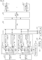
- FIG. 2 is a block diagram illustrating a transmit end for forming a Tx beam according to the present disclosure. Here, it is assumed that the transmit end applies a digital/ analog hybrid beamforming scheme.
- the transmit end includes a 'K' number of channel encoding units 200-1 to 200-K, a MIMO encoding unit 210, a precoding unit 220, an 'N T ' number of Radio Frequency (RF) paths 230-1 to 230-N T , an 'N T ' number of antenna units 250-1 to 250-N T , a beam setting unit 260, a Tx control unit 270, and a feedback information receiving unit 280.
- RF Radio Frequency
- the 'K' number of channel encoding units 200-1 to 200-K each include a channel encoder and a modulator, and encode and modulate signals to be transmitted to a receive end.
- the MIMO encoding unit 210 To transmit signals through the 'N T ' number of antenna units 250-1 to 250-N T , the MIMO encoding unit 210 multiplexes modulation signals provided from the 'K' number of channel encoding units 200-1 to 200-K into signals to be transmitted through an 'N T ' number of streams.
- the precoding unit 220 precodes an 'N T ' number of signals provided from the MIMO encoding unit 210 into precodes for digital beamforming, and provides the precodes to the respective RF paths 230-1 to 230-N T .
- the 'N T ' number of RF paths 230-1 to 230-N T each process to output signals provided from the precoding unit 220 through the corresponding antenna units 250-1 to 250-N T .
- the 'N T ' number of RF paths 230-1 to 230-N T have the same construction. Thus, in the following description, a construction of the first RF path 230-1 is described as representative. The remaining RF paths 230-2 to 230-N T have the same construction as the first RF path 230-1.
- the first RF path 230-1 includes an N A number of modulators 232-11 to 232-1N A , an analog beamformer 290, and an N A number of power amplifiers 240-11 to 240-1N A .
- 'N A ' represents the number of antenna elements constituting the antenna unit 1 250-1.
- the N A number of modulators 232-11 to 232-1N A each modulate signals provided from the precoding unit 220 according to a communication scheme.
- the N A number of modulators 232-11 to 232-1N A each include an Inverse Fast Fourier Transform (IFFT) operator and a Digital to Analog Converter (DAC).
- IFFT Inverse Fast Fourier Transform
- DAC Digital to Analog Converter
- the IFFT operator converts a signal provided from the precoding unit 220 into a time domain signal through IFFT operation.
- the DAC converts the time domain signal provided from the IFFT operator into an analog signal.
- the analog beamformer 290 shifts phases of an 'N A ' number of transmit signals provided from the 'N A ' number of modulators 232-11 to 232-1N A according to a Tx beam weight provided from the beam setting unit 260.
- the analog beamformer 290 includes a plurality of phase shifters 234-11 to 234-1N A and 236-11 to 236-1N A , and combiners 238-11 to 238-1N A .
- the 'N A ' number of modulators 232-11 to 232-1N A each separate an output signal into an 'N A ' number of signals and output the 'N A ' number of signals to the respective phase shifters 234-11 to 234-1N A and 236-11 to 236-1N A .
- the phase shifters 234-11 to 234-1N A and 236-11 to 236-1N A each shift phases of signals provided from the 'N A ' number of modulators 232-11 to 232-1N A according to a Tx beam weight provided from the beam setting unit 260.
- the combiners 238-11 to 238-1N A combine output signals of the phase shifters 234-11 to 234-1N A and 236-11 to 236-1N A corresponding to antenna elements.
- the power amplifiers 240-11 to 240-1N A each amplify power of signals provided from the combiners 238-11 to 238-1N A and output the signals to the external through the antenna unit 1 250-1.
- the beam setting unit 260 selects a Tx beam pattern to be used for transmitting a signal according to the control of the Tx control unit 270, and provides a Tx beam weight dependent on the selected Tx beam pattern to the analog beamformer 290. For example, the beam setting unit 260 selects at least one Tx beam pattern to be used for diversity transmission considering channel information on each Tx beam pattern provided from the feedback information receiving unit 280 according to the control of the Tx control unit 270. As another example, the beam setting unit 260 selects at least one Tx beam pattern and at least one Rx beam pattern to be used for diversity transmission considering channel information on each Tx beam pattern provided from the feedback information receiving unit 280 according to the control of the Tx control unit 270.
- the beam setting unit 260 selects a plurality of Tx beam patterns and a plurality of Rx beam patterns to be used in spatial multiplexing transmission considering channel information on each Tx beam pattern provided from the feedback information receiving unit 280 according to the control of the Tx control unit 270.
- the beam setting unit 260 selects a Tx beam pattern or Tx/ Rx beam pattern for multiple antenna transmission as illustrated in FIG. 8 .
- the Tx control unit 270 controls the beam setting unit 260 to select a Tx beam pattern for forming a Tx beam. For example, the Tx control unit 270 controls the beam setting unit 260 to be able to transmit a reference signal through each Tx beam pattern supportable by the transmit end. That is, the Tx control unit 270 controls the beam setting unit 260 to select a Tx beam pattern to transmit a reference signal. As another example, the Tx control unit 270 controls the beam setting unit 260 to select a Tx beam pattern or Tx/Rx beam pattern to be used for diversity transmission considering beamforming information of a receive end.
- the Tx control unit 270 controls the beam setting unit 260 to select Tx/Rx beam pattern to be used for spatial multiplexing considering beamforming information of a receive end.
- the beamforming information of the receive end includes Rx beamforming support or non-support, the number of supportable Rx beam patterns, concurrent usability or non-usability of a plurality of Rx beams, information on the number of concurrently usable Rx beams, the number of usable MIMO streams, and the like.
- the Tx control unit 270 controls to send a channel information request to a receive end.
- the Tx control unit 270 controls to transmit a broadcasting signal for a request for channel information of a Tx beam pattern or a control message (e.g., REP-REQ) for the channel information request.
- the Tx control unit 270 sends a channel information request to the receive end by allocating a resource for channel information transmission to the receive end.
- the Tx control unit 270 may control to transmit report form information for feeding back channel information to the receive end, together with the channel information request.
- the report form information includes at least one of the number of Tx beam patterns to feed back channel information, the number of Tx beam patterns and Rx beam patterns to feed back the channel information, the number of Tx beam patterns by Rx beam to feed back the channel information, and a reference value for beam selection and channel information feedback.
- the reference value for beam selection and channel information feedback includes at least one of an absolute value of a channel quality, a relative value of the channel quality for a reference beam combination, a time variance of a beam combination channel quality and a standard deviation of the beam combination channel quality, and a correlation value between beam combinations.
- the feedback information receiving unit 280 receives information fed back from a receive end, and outputs the feedback information to the precoding unit 220, the beam setting unit 260, and the Tx control unit 270.
- the Tx control unit 270 controls the beam setting unit 260 to select a Tx beam pattern or Tx/Rx beam pattern to be used for diversity transmission in consideration of beamforming information of the receive end. For example, when the receive end supports Rx beamforming and concurrently can receive a signal using a plurality of Rx beam patterns, the Tx control unit 270 controls the beam setting unit 260 to select a plurality of Tx beam patterns for a plurality of Rx beam patterns. For another example, when the receive end supports Rx beamforming but concurrently cannot receive a signal using a plurality of Rx beam patterns, the Tx control unit 270 controls the beam setting unit 260 to select a plurality of Tx beam patterns for a plurality of Rx beam patterns.
- the Tx control unit 270 controls the beam setting unit 260 to select one Tx beam pattern for one Rx beam pattern.
- the Tx control unit 270 controls the beam setting unit 260 to select a plurality of Tx beam patterns.
- the Tx control unit 270 controls the beam setting unit 260 to select one Tx beam pattern. That is, the Tx control unit 270 controls the beam setting unit 260 to select a Tx beam pattern or Tx/Rx beam pattern for diversity transmission as illustrated in FIG. 8 .
- the transmit end may further include a channel estimator for estimating a channel for an Rx beam pattern.
- FIG. 3 is a block diagram illustrating a receive end for forming a Rx beam according to the present disclosure. Here, it is assumed that the receive end applies a digital/ analog hybrid beamforming scheme.
- the receive end includes an 'N R ' number of antenna units 300-1 to 300-N R , an 'N R ' number of RF paths 310-1 to 310-N R , a postprocessor 320, a MIMO decoding unit 330, a 'T' number of channel decoding units 340-1 to 340-T, a channel estimating unit 350, a feedback control unit 360, and a beam setting unit 370.
- the 'N R ' number of RF paths 310-1 to 310-N R each process signals received through the corresponding antenna units 300-1 to 300-N R .
- the 'N R ' number of RF paths 310-1 to 310-N R have the same construction.
- a construction of the first RF path 310-1 is described as representative.
- the remaining RF paths 310-2 to 310-N R have the same construction as the first RF path 310-1.
- the first RF path 310-1 includes an analog beamformer 380 and an 'N B ' number of modulators 318-11 to 318-1N B .
- 'N B ' represents the number of antenna elements constituting the antenna unit 1 300-1.
- the analog beamformer 380 shifts phases of an 'N B ' number of receive signals provided from antenna elements constituting the antenna unit 1 300-1 according to a Tx beam weight provided from the beam setting unit 370.
- the analog beamformer 380 includes a plurality of phase shifters 312-11 to 312-1N B and 314-11 to 314-1N B and combiners 316-11 to 316-1N B .
- the antenna elements constituting the antenna unit 1 300-1 separate receive signals into an 'N B ' number of signals and output the signals to the respective phase shifters 312-11 to 312-1N B and 314-11 to 314-1NB.
- the respective phase shifters 312-11 to 312-1N B and 314-11 to 314-1NB shift phases of signals provided from the antenna elements constituting the antenna unit 1 300-1.
- the combiners 316-11 to 316-1NB combine output signals of the phase shifters 312-11 to 312-1N B and 314-11 to 314-1N B corresponding to the antenna elements.
- the 'N B ' number of demodulators 318-11 to 318-1N B each demodulate receive signals provided from the combiners 316-11 to 316-1N B according to a communication scheme.
- the 'N B ' number of demodulators 318-11 to 318-1N B each include an Analog to Digital Converter (ADC) and a Fast Fourier Transform (FFT) operator.
- ADC Analog to Digital Converter
- FFT Fast Fourier Transform
- the ADC converts receive signals provided from the combiners 316-11 to 316-1N B into digital signals.
- the FFT operator converts a signal provided from the ADC into a frequency domain signal through FFT operation.
- the postprocessor 320 post decodes signals provided from the 'N R ' number of RF paths 310-1 to 310-N R according to a precoding scheme of a transmit end and provides the signals to the MIMO decoding unit 330.
- the MIMO decoding unit 330 multiplexes an 'N R ' number of receive signals provided from the postprocessor 320 into a 'T' number of signals to decode the receive signals in the 'T' number of channel decoding units 340-1 to 340-T.
- the 'T' number of channel decoding units 340-1 to 340-T each include a demodulator and a channel decoder, and demodulate and decode signals provided from the transmit end.
- the channel estimating unit 350 estimates channel information on each Tx beam pattern by means of a reference signal that the transmit end transmits through each Tx beam pattern. For example, when the receive end supports Rx beamforming, the channel estimating unit 350 estimates channel information on a Tx beam pattern by each supportable Rx beam pattern as illustrated in FIG. 6 . For another example, when the receive end does not support Rx beamforming, the channel estimating unit 350 estimates channel information on a Tx beam pattern as illustrated in FIG. 5 . In an embodiment, when the transmit end requests for channel information, the channel estimating unit 350 estimates channel information on each Tx beam pattern.
- the channel information includes at least one of a Signal to Noise Ratio (SNR), a Carrier power Interference and Noise power Ratio (CINR) and a Receive Signal Strength Indicator (RSSI).
- SNR Signal to Noise Ratio
- CINR Carrier power Interference and Noise power Ratio
- RSSI Receive Signal Strength Indicator
- the feedback control unit 360 feeds back channel information on each Tx beam pattern estimated in the channel estimating unit 350, to the transmit end.
- the feedback control unit 360 feeds back channel information on each Tx beam pattern to the transmit end according to report form information provided from the transmit end.
- the report form information includes at least one of the number of Tx beam patterns to feed back channel information, the number of Tx beam patterns and Rx beam patterns to feed back the channel information, the number of Tx beam patterns by Rx beam to feed back the channel information, and a reference value for beam selection and channel information feedback.
- the reference value for beam selection and channel information feedback includes at least one of an absolute value of a channel quality, a relative value of the channel quality for a reference beam combination, a time variance of a beam combination channel quality and a standard deviation of the beam combination channel quality, and a correlation value between beam combinations.
- the feedback control unit 360 feeds back channel information on an 'M' number of Tx beam patterns of good channel states according to the report form information.
- the feedback control unit 360 can feed back channel information on a 'P' number of Tx beam patterns of channel states greater than or equal to a reference value according to the report form information.
- the feedback control unit 360 may feed back channel information on an 'N' number of Tx beam patterns of good channel states by Rx beam pattern according to the report form information.
- the feedback control unit 360 may feed back channel information on a 'T' number of Tx beam patterns of channel states greater than a reference value by Rx beam pattern according to the report form information.
- the feedback control unit 360 may feed back channel information on a Tx beam pattern of the best channel state and at least one Tx beam pattern of a channel state included within a constant range according to the report form information.
- the feedback control unit 360 may feed back channel information on a Tx beam pattern of the best channel state by Rx beam pattern and at least one Tx beam pattern of a channel state included within a constant range according to the report form information.
- the 'M', 'P', 'N', and 'T' denote integers representing the number of Tx beam patterns for feeding back.
- the feedback control unit 360 transmits Rx beamforming capability information to the transmit end.
- the feedback control unit 360 transmits its own Rx beamforming capability information to the transmit end in a capability negotiation process with the transmit end.
- the capability negotiation with the transmit end can occur at the time of initial network entry and network re-entry.
- the beam setting unit 370 provides an Rx beam weight to the analog beamformer 380 such that the receive end receives a signal according to an Rx beam pattern corresponding to a Tx beam pattern selected by the transmit end among a plurality of supportable Rx beam patterns.
- the beam setting unit 370 determines an Rx beam pattern to be used for receiving a signal, in a control signal provided from the transmit end.
- a receive end transmits Rx beamforming capability information to a transmit end using a feedback control unit.
- the receive end may further include a transmitter for transmitting Rx beamforming capability information to the transmit end.
- the following description is made for a method for feeding back channel information on a Tx beam pattern in a receive end.
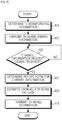
- FIG. 4 illustrates a procedure for feeding back channel information on a beam pattern in a receive end according to an embodiment of the present disclosure.
- the receive end determines Tx beamforming information of a transmit end. For example, the receive end receives the Tx beamforming information from the transmit end.
- the Tx beamforming information includes the number of Tx beam patterns supportable by the transmit end, Tx beam transmission timing and the like.
- the receive end proceeds to step 403 and transmits its own Rx beamforming capability information to the transmit end.
- the receive end transmits its own Rx beamforming capability information to the transmit end in a capability negotiation process with the transmit end.
- the Rx beamforming capability information includes Rx beamforming support or non-support, the number of supportable Rx beam patterns, concurrent usability or non-usability of a plurality of Rx beams, information on the number of concurrently usable Rx beams, the number of usable MIMO streams and the like.
- the receive end can construct the Rx beamforming capability information as in Table 1 below.
- the number of Rx beams concurrently usable in the receive end may be expressed as the number of Rx RF chains of the receive end.
- the receive end proceeds to step 405 and determines if the transmit end requests for channel information on each Tx beam pattern. For example, the receive end determines if a broadcasting signal for a channel information request or a control message (e.g., REP-REQ) for the channel information request is received from the transmit end. For another example, the receive end determines if the transmit end allocates a resource for channel information transmission. In an embodiment, when the transmit end allocates the resource for channel information transmission, the receive end recognizes that the transmit end requests for channel information.
- a broadcasting signal for a channel information request or a control message e.g., REP-REQ
- the receive end proceeds to step 407 and determines a report form for transmitting the channel information.
- the receive end receives report form information from the transmit end.
- the report form information includes at least one of the number of Tx beam patterns to feed back channel information, the number of Tx beam patterns and Rx beam patterns to feed back the channel information, the number of Tx beam patterns by Rx beam to feed back the channel information, and a reference value for beam selection and channel information feedback.
- the reference value for beam selection and channel information feedback includes at least one of an absolute value of a channel quality, a relative value of the channel quality for a reference beam combination, a time variance of a beam combination channel quality and a standard deviation of the beam combination channel quality, and a correlation value between beam combinations.
- the receive end proceeds to step 409 and estimates a channel for each supportable Tx beam pattern of the transmit end. For example, the receive end estimates a channel for each Tx beam pattern using a reference signal that the transmit end transmits through each beam pattern.
- the receive end estimates channel information on a Tx beam pattern of the transmit end by each Rx beam pattern supportable by the receive end as illustrated in FIG. 6 .
- the receive end estimates channel information on a Tx beam pattern as illustrated in FIG. 5 .
- the receive end After estimating the channel for the Tx bean pattern, the receive end proceeds to step 411 and feeds back the channel information on the Tx beam pattern to the transmit end according to the report form determined in step 407. For example, the receive end feeds back channel information on an 'M' number of Tx beam patterns of good channel states according to the report form information. As another example, the receive end feeds back channel information on a 'P' number of Tx beam patterns of channel states greater than a reference value according to the report form information. As a further example, when the receive end supports Rx beamforming, the receive end feeds back channel information on an 'M' number of Tx beam patterns of good channel states by Rx beam pattern according to the report form information.
- the receive end when the receive end supports Rx beamforming, the receive end feeds back channel information on a 'P' number of Tx beam patterns of channel states greater than a reference value by Rx beam pattern according to the report form information. As still another example, the receive end may feed back channel information on a Tx beam pattern of the best channel state and at least one Tx beam pattern of a channel state included within a constant range according to the report form information. As still another example, when the receive end supports Rx beamforming, the receive end may feed back channel information on a Tx beam pattern of the best channel state by Rx beam pattern and at least one Tx beam pattern of a channel state included within a constant range according to the report form information.
- the 'M', 'P', 'N', and 'T' denote integers representing the number of Tx beam patterns for feeding back.
- the channel state includes at least one of a CINR, a Received Signal Strength Indication (RSSI), and channel correlation between beam patterns.
- RSSI Received Signal Strength Indication
- the receive end terminates the algorithm according to the embodiment of the present disclosure.
- a receive end feeds back channel information on a Tx beam pattern according to a report form provided from a transmit end.
- the receive end may feed back channel information on Tx beam patterns measured by itself to the transmit end without considering a report form of the transmit end.
- the following description is made for a method for estimating a channel for a Tx beam pattern in a receive end not supporting Rx beamforming.
- FIG. 5 illustrates a procedure for estimating a channel for a beam pattern in a receive end according to an embodiment of the present disclosure.
- the receive end determines a reference signal for an ith Tx beam pattern. For example, the receive end receives the reference signal that the transmit end transmits through the ith Tx beam pattern.
- the 'i' is an index of a Tx beam pattern through which the transmit end transmits the reference signal, and has an initial value of '0'.
- the receive end After determining the reference signal of the ith Tx beam pattern in step 501, the receive end proceeds to step 503 and estimates a channel for the ith Tx beam pattern using the reference signal of the ith Tx beam pattern.
- the receive end proceeds to step 505 and updates the index (i) of the Tx beam pattern. For example, the receive end increases the index (i) of the Tx beam pattern by one level (i++).
- the receive end After updating the index (i) of the Tx beam pattern in step 505, the receive end proceeds to step 507 and compares the updated index (i) of the Tx beam pattern with the number (N BF_TX ) of Tx beam patterns supportable by the transmit end, determining if it has estimated channels for all Tx beam patterns supportable by the transmit end.
- the receive end When the updated index (i) of the Tx beam pattern is less than the number (N BF_TX ) of Tx beam patterns supportable by the transmit end (i ⁇ N BF_TX ), the receive end recognizes that it has not estimated the channels for all Tx beam patterns supportable by the transmit end. Accordingly, the receive end returns to step 501 and determines a reference signal for the ith Tx beam pattern.
- the index (i) of the Tx beam pattern has a value updated in step 505.
- the receive end recognizes that it has estimated the channels for all Tx beam patterns supportable by the transmit end. Accordingly, the receive end proceeds to step 411 of FIG. 4 and feeds back channel information on the Tx beam pattern to the transmit end.
- the following description is made for a method for estimating a channel for a Tx beam pattern in a receive end supporting Rx beamforming.
- FIG. 6 illustrates a procedure for estimating a channel for a beam pattern in a receive end according to another embodiment of the present disclosure.
- the receive end when the receive end estimates a channel of a Tx beam pattern in step 409 of FIG. 4 , in step 601, the receive end sets an Rx beam for receiving a signal to a jth Rx beam pattern.
- the 'j' is an index of an Rx beam pattern supportable by the receive end, and has an initial value of '0'.
- the receive end proceeds to step 603 and determines a reference signal for an ith Tx beam pattern.
- the receive end receives the reference signal that the transmit end transmits through the ith Tx beam pattern.
- the 'i' is an index of a Tx beam pattern through which the transmit end transmits the reference signal, and has an initial value of '0'.
- the receive end After determining the reference signal of the ith Tx beam pattern in step 603, the receive end proceeds to step 605 and estimates a channel for the ith Tx beam pattern received through the jth Rx beam pattern using the reference signal of the ith Tx beam pattern.
- the receive end proceeds to step 607 and updates the index (i) of the Tx beam pattern. For example, the receive end increases the index (i) of the Tx beam pattern by one level (i++).
- the receive end After updating the index (i) of the Tx beam pattern in step 607, the receive end proceeds to step 609 and compares the updated index (i) of the Tx beam pattern with the number (N BF_TX ) of Tx beam patterns supportable by the transmit end, determining if it has estimated channels for all Tx beam patterns supportable by the transmit end.
- the receive end When the updated index (i) of the Tx beam pattern is less than the number (N BF_TX ) of Tx beam patterns supportable by the transmit end (i ⁇ N BF_TX ), the receive end recognizes that it has not estimated the channels for all Tx beam patterns supportable by the transmit end. Accordingly, the receive end returns to step 603 and determines a reference signal for the ith Tx beam pattern.
- the index (i) of the Tx beam pattern has a value updated in step 607.
- the receive end recognizes that it has estimated the channels for all Tx beam patterns supportable by the transmit end. Accordingly, the receive end proceeds to step 611 and updates the index (j) of the Rx beam pattern. For instance, the receive end increases the index (j) of the Rx beam pattern by one level (j++).
- the receive end After updating the index (j) of the Rx beam pattern, the receive end proceeds to step 613 and compares the updated index (j) of the Rx beam pattern with the number (N BF_RX ) of Rx beam patterns supportable by the receive end, determining if it has estimated channels of Tx beam patterns for all Rx beam patterns supportable by the receive end.
- the receive end When the updated index (j) of the Rx beam pattern is less than the number (N BF_RX ) of Rx beam patterns supportable by the receive end (j ⁇ N BF_RX ), the receive end recognizes that it has not estimated channels of Tx beam patterns for all Rx beam patterns supportable by the receive end. Accordingly, the receive end returns to step 601 and sets an Rx beam for receiving a signal to a jth Rx beam pattern.
- the index (j) of the Rx beam pattern has a value updated in step 611.
- the receive end recognizes that it has estimated channels of Tx beam patterns for all Rx beam patterns supportable by the receive end. Accordingly, the receive end proceeds to step 411 of FIG. 4 and feeds back channel information of the Tx beam pattern for the Rx beam pattern to the transmit end.
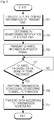
- FIG. 7 illustrates a procedure for forming a beam in a transmit end according to an embodiment of the present disclosure.
- the transmit end transmits its own Tx beamforming information to a receive end.
- the Tx beamforming information includes the number of Tx beam patterns supportable by the transmit end, Tx beam transmission timing and the like.
- the transmit end proceeds to step 703 and determines Rx beamforming capability information of a receive end. For example, upon network entry or handover of the receive end, the transmit end receives the Rx beamforming capability information of the receive end from the receive end in a capability negotiation process with the receive end.
- the Rx beamforming capability information includes Rx beamforming support or non-support, the number of supportable Rx beam patterns, concurrent usability or non-usability of a plurality of Rx beams, information on the number of concurrently usable Rx beams, and the like.
- the transmit end can determine Rx beamforming capability information constructed as in Table 1 above.
- the transmit end After determining the Rx beamforming capability information of the receive end, the transmit end proceeds to step 705 and requests for channel information on a Tx beam pattern supportable by itself. For example, the transmit end transmits a broadcasting signal for a request for channel information of a Tx beam pattern or a control message (e.g., REP_REQ) for the channel information request to the receive end. For another example, the transmit end allocates a resource for channel information transmission to the receive end. In an embodiment, the transmit end may transmit report form information for feeding back channel information to the receive end, together with the channel information request.
- the report form information includes the number of Tx beam patterns to feed back channel information, a reference value to feed back the channel information, and the like.
- the transmit end proceeds to step 707 and determines if channel information on a Tx beam pattern is received from the receive end.
- the transmit end proceeds to step 709 and performs Tx scheduling considering the channel information on the Tx beam pattern provided from the receive end. For example, as illustrated in FIG. 8 , the transmit end selects at least one Tx beam pattern for at least one Rx beam pattern to be used for transmitting a signal to the receive end in consideration of the channel information on the Tx beam pattern provided from the receive end.
- the transmit end After performing the Tx scheduling in step 709, the transmit end proceeds to step 711 and transmits a signal to the receive end according to Tx scheduling information. That is, the transmit end transmits the signal to the receive end through the Tx beam pattern selected through the Tx scheduling.
- the transmit end terminates the algorithm according to the embodiment of the present disclosure.
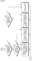
- FIG. 8 illustrates a scheduling procedure for diversity transmission in a transmit end according to an embodiment of the present disclosure.
- the transmit end when the transmit end performs Tx scheduling in step 709 of FIG. 7 , the transmit end proceeds to step 801 and determines Rx beamforming capability information of a receive end. For example, the transmit end determines the Rx beamforming capability information that is provided from the receive end in step 703.
- the Rx beamforming capability information includes Rx beamforming support or non-support, the number of supportable Rx beam patterns, concurrent usability or non-usability of a plurality of Rx beams, information on the number of concurrently usable Rx beams, the number of usable MIMO streams, and the like.
- the transmit end proceeds to step 803 and determines if the receive end to receive a signal transmitted by the transmit end supports Rx beamforming according to the Rx beamforming capability information of the receive end.
- the transmit end proceeds to step 805 and determines if the receive end can concurrently receive a signal using a plurality of Rx beam patterns.
- step 805 When it is determined in step 805 that the receive end can concurrently receive the signal using the plurality of Rx beam patterns, the transmit end proceeds to step 807 and determines if the transmit end concurrently can transmit the signal using a plurality of Tx beam patterns.
- the transmit end proceeds to step 809 and determines if the receive end supports a multiple MIMO stream. For example, the transmit end determines if the receive end supports the multiple MIMO stream considering information of the number of usable MIMO streams included in the Rx beamforming capability information of the receive end.
- the transmit end decides that it transmits a signal to the receive end using a spatial multiplexing transmission scheme. According to this, the transmit end proceeds to step 811 and selects a plurality of Rx beam patterns and a plurality of Tx beam patterns for spatial multiplexing transmission. For example, the transmit end determines channel information of Tx beam patterns for at least one Rx beam pattern supportable by the receive end provided from the receive end. After that, the transmit end selects a plurality of Tx beam patterns for a plurality of Rx beam patterns of good channel states among the channel information of the Tx beam patterns for the each Rx beam pattern.
- the transmit end decides that it transmits a signal to the receive end using a diversity transmission scheme. According to this, the transmit end proceeds to step 813 and selects a plurality of Tx beam patterns and a plurality of Rx beam patterns for diversity transmission. For example, the transmit end determines channel information of Tx beam patterns for at least one Rx beam pattern supportable by the receive end provided from the receive end. And then, the transmit end selects a plurality of Tx beam patterns for a plurality of Rx beam patterns having good channel states among the channel information of the Tx beam patterns for each Rx beam pattern.
- step 807 when it is determined in step 807 that the transmit end concurrently cannot transmit the signal using the plurality of Tx beam patterns, the transmit end proceeds to step 815 and determines whether to provide diversity transmission through sequential transmission.
- step 805 when it is determined in step 805 that the receive end cannot concurrently receive the signal using the plurality of Rx beam patterns, the transmit end proceeds to step 815 and determines whether to provide the diversity transmission through the sequential transmission.
- the transmit end proceeds to step 817 and selects at least one Tx beam pattern and at least one Rx beam pattern for the diversity transmission. For example, the transmit end determines channel information of Tx beam patterns for at least one Rx beam pattern supportable by the receive end provided from the receive end. And then, the transmit end selects a plurality of Tx beam patterns to transmit the same signal at a different timing and a plurality of Rx beam patterns for receiving the same signal transmitted by the transmit end at a different timing. For another example, the transmit end may select one Tx beam pattern for one Rx beam pattern for transmitting the same information at a different timing.
- step 815 when it is determined in step 815 that the transmit end does not provide the diversity transmission through the sequential transmission, the transmit end recognizes that it does not perform the diversity transmission. Accordingly, the transmit end proceeds to step 819 and selects any one Tx beam pattern to be used for transmitting a signal correspondingly to any one Rx beam pattern of the receive end to be transmitted by the transmit end, in consideration of channel information of Tx beam patterns for each Rx beam pattern.
- step 803 when it is determined in step 803 that the receive end does not support the Rx beamforming, the transmit end proceeds to step 821 and determines whether it concurrently can transmit a signal using a plurality of Tx beam patterns.
- the transmit end proceeds to step 823 and determines if the receive end supports a multiple MIMO stream. For example, the transmit end determines if the receive end supports the multiple MIMO stream in consideration of information of the number of usable MIMO streams included in the Rx beamforming capability information of the receive end.
- the transmit end decides that it transmits a signal to the receive end using a spatial multiplexing transmission scheme. According to this, the transmit end proceeds to step 825 and selects a plurality of Tx beam patterns for spatial multiplexing transmission.
- the transmit end decides that it transmits a signal to the receive end using a diversity transmission scheme. According to this, the transmit end proceeds to step 827 and selects a plurality of Tx beam patterns for a plurality of Rx beam patterns for diversity transmission.
- step 821 when it is determined in step 821 that the transmit end concurrently cannot transmit the signal using the plurality of Tx beam patterns, the transmit end proceeds to step 829 and determines whether to provide the diversity transmission through the sequential transmission.
- the transmit end proceeds to step 831 and selects at least one Tx beam pattern for diversity transmission. For example, the transmit end determines channel information of Tx beam patterns provided from the receive end. After that, the transmit end selects a plurality of Tx beam patterns to transmit the same signal at a different timing, in consideration of the channel information of the Tx beam patterns. For another example, the transmit end selects one Tx beam pattern for transmitting the same information at a different timing, in consideration of the channel information of the Tx beam patterns.
- step 829 when it is determined in step 829 that the transmit end does not provide the diversity transmission through the sequential transmission, the transmit end proceeds to step 833 and selects any one Tx beam pattern to be used for transmitting a signal considering the channel information of the Tx beam patterns provided from the receive end.
- the transmit end proceeds to step 711 of FIG. 7 and transmits a signal to the receive end through the Tx beam pattern selected through the transmission scheduling.
- the transmit end performs transmission scheduling using channel information on a Tx beam pattern provided from the receive end.
- the transmit end may transmit a signal considering a Tx beam pattern or Tx/Rx beam pattern selected in the receive end. That is, as illustrated in FIG. 8 , the receive end can perform transmission scheduling for signal transmission of the transmit end.
- the transmit end selects any one of a spatial multiplexing transmission scheme and a diversity transmission scheme considering a beam management capability of the transmit end, a beam management capability of the receive end, and a MIMO stream management capability of the receive end. For example, the transmit end estimates information of a channel correlation between Tx beam patterns or a channel correlation between Tx/Rx beam pattern combinations considering the beam management capability of the transmit end, the beam management capability of the receive end, and the MIMO stream management capability of the receive end. After that, the transmit end selects any one of the spatial multiplexing transmission scheme and the diversity transmission scheme considering the information of the channel correlation between the Tx beam patterns or the channel correlation between the Tx/Rx beam pattern combinations.
- the transmit end estimates a gain for each multiple antenna transmission scheme considering the beam management capability of the transmit end, the beam management capability of the receive end, and the MIMO stream management capability of the receive end. After that, the transmit end may select any one of the spatial multiplexing transmission scheme and the diversity transmission scheme considering the gain for each multiple antenna transmission scheme.
- the following description is made for a technology for managing a Tx/Rx beam according to uplink multiple antenna transmission.
- FIG. 9 illustrates a procedure for transmitting Tx beamforming information in a receive end according to an exemplary embodiment of the present invention.
- the receive end transmits its own Tx beamforming capability information to a transmit end.
- the receive end transmits its own Tx beamforming capability information to the transmit end in a capability negotiation process with the transmit end.
- the Tx beamforming capability information includes Tx beamforming support or non-support, the number of supportable Tx beam patterns, concurrent usability or non-usability of a plurality of Tx beams, information on the number of concurrently usable Tx beams, the number of usable MIMO streams, and the like.
- the receive end can construct the Tx beamforming capability information as in Table 2 below.
- Table 2 Capability to support Tx Beamforming 0b0: non-support 0b1: support Max number of Tx Beamforming patterns 0b00: 1 ⁇ 0b11 1: 8 patterns Capability of UL MIMO support 0b0: non-support 0b1: support Max number of UL MIMO streams 0b000: 1 stream ⁇ 0b111: 8 streams Capability of MS transmitting concurrently with different Tx Beamforming patterns 0b0: non-support 0b1: support Number of MS Tx Beamforming patterns supported simultaneously (Number of MS TX Chains) 0b00: 1 ⁇ 0b11: 4
- the number of Tx beams concurrently usable in the receive end can be expressed as the number of Tx RF chains of the receive end.
- the receive end proceeds to step 903 and transmits a reference signal through each Tx beam pattern.
- the receive end after transmitting the reference signal, the receive end transmits a signal to the transmit end according to reception scheduling information provided from the transmit end.
- FIG. 10 illustrates a procedure for forming an Rx beam in a transmit end according to an exemplary embodiment of the present invention.
- the transmit end determines Tx beamforming capability information of a receive end. For example, upon network entry or handover of the receive end, the transmit end receives the Tx beamforming capability information of the receive end from the receive end in a capability negotiation process with the receive end.
- the Tx beamforming capability information includes Tx beamforming support or non-support, the number of supportable Tx beam patterns, concurrent usability or non-usability of a plurality of Tx beams, information on the number of concurrently usable Tx beams, the number of usable MIMO streams, and the like.
- the transmit end can determine Tx beamforming capability information of the receive end constructed as in Table 2 above.
- the transmit end After determining the Tx beamforming capability information of the receive end in step 1001, the transmit end proceeds to step 1003 and estimates a channel for each supportable Tx beam pattern of the receive end. For example, the transmit end estimates a channel for each Tx beam pattern using a reference signal that the receive end transmits through each Tx beam pattern. If the transmit end supports Rx beamforming, the transmit end estimates channel information on a Tx beam pattern of the receive end by each Rx beam pattern.
- the transmit end After determining the channel information on the Tx beam pattern of the receive end in step 1003, the transmit end proceeds to step 1005 and performs reception scheduling considering the channel information on the Tx beam pattern of the receive end. For example, as illustrated in FIG. 11 , the transmit end selects at least one Tx beam pattern for at least one Rx beam pattern to be used for receiving a signal from the receive end considering the channel information on the Tx beam pattern of the receive end. In an exemplary embodiment, the transmit end transmits reception scheduling information to the receive end.
- the transmit end After performing the reception scheduling in step 1005, the transmit end proceeds to step 1007 and receives a signal from the receive end according to the reception scheduling information. That is, the transmit end receives the signal from the receive end through the Rx beam pattern selected through the reception scheduling.
- FIG. 11 illustrates a scheduling procedure for uplink beamforming in a transmit end according to an exemplary embodiment of the present invention.
- the transmit end when the transmit end performs reception scheduling in step 1005 of FIG. 10 , the transmit end proceeds to step 1101 and determines Tx beamforming capability information of a receive end. For example, in step 1101, the transmit end determines the Tx beamforming capability information of the receive end provided from the receive end.
- the Tx beamforming capability information includes Tx beamforming support or non-support, the number of supportable Tx beam patterns, concurrent usability or non-usability of a plurality of Tx beams, information on the number of concurrently usable Tx beams, the number of usable MIMO streams, and the like.
- the transmit end proceeds to step 1103 and determines if the receive end supports Tx beamforming according to the Tx beamforming capability information of the receive end.
- step 1103 When it is determined in step 1103 that the receive end supports the Tx beamforming, the transmit end proceeds to step 1105 and determines if the receive end concurrently can transmit a signal using a plurality of Tx beam patterns.
- step 1105 When it is determined in step 1105 that the receive end concurrently can transmit the signal using the plurality of Tx beam patterns, the transmit end proceeds to step 1107 and determines if the transmit end can concurrently receive the signal using a plurality of Rx beam patterns.
- the transmit end proceeds to step 1109 and determines if the receive end supports a multiple MIMO stream. For example, the transmit end determines if the receive end supports the multiple MIMO stream considering information of the number of usable MIMO streams included in the Tx beamforming capability information of the receive end.
- the transmit end decides that it receives a signal from the receive end using a spatial multiplexing transmission scheme. According to this, the transmit end proceeds to step 1111 and selects a plurality of Rx beam patterns and a plurality of Tx beam pattern for spatial multiplexing transmission. For example, the transmit end determines channel information of Rx beam patterns for at least one Tx beam pattern supportable by the receive end provided from the receive end. After that, the transmit end selects a plurality of Rx beam patterns for a plurality of Tx beam patterns of good channel states among the channel information of the Rx beam patterns for the each Tx beam pattern.
- the transmit end decides that it receives a signal from the receive end using a diversity transmission scheme. According to this, the transmit end proceeds to step 1113 and selects a plurality of Rx beam patterns and a plurality of Tx beam patterns for diversity transmission. For example, the transmit end determines channel information of Rx beam patterns for at least one Tx beam pattern supportable by the receive end provided from the receive end. After that, the transmit end selects a plurality of Rx beam patterns for a plurality of Tx beam patterns of good channel states among the channel information of the Rx beam patterns for the each Tx beam pattern.
- step 1107 when it is determined in step 1107 that the transmit end concurrently cannot receive the signal using the plurality of Rx beam patterns, the transmit end proceeds to step 1115 and determines whether to provide diversity transmission through sequential reception.
- step 1105 when it is determined in step 1105 that the receive end concurrently cannot transmit the signal using the plurality of Tx beam patterns, the transmit end proceeds to step 1115 and determines whether to provide the diversity transmission through the sequential reception.
- the transmit end proceeds to step 1117 and selects at least one Rx beam pattern and at least one Tx beam pattern for the diversity transmission. For example, the transmit end determines channel information of Rx beam patterns for at least one Tx beam pattern supportable by the receive end provided from the receive end. After that, the transmit end selects a plurality of Tx beam patterns to transmit the same signal at a different timing in the receive end and a plurality of Rx beam patterns to receive the same signal transmitted by the receive end at a different timing. For another example, the transmit end may select one Tx beam pattern for one Rx beam pattern for transmitting the same information at a different timing in the receive end.
- the transmit end recognizes that it does not perform the diversity transmission. According to this, the transmit end proceeds to step 1119 and selects a Tx beam pattern of the receive end to transmit a signal and an Rx beam pattern of the transmit end to receive a signal, in consideration of the channel information of the Tx beam patterns for the each Rx beam pattern.
- the transmit end proceeds to step 1121 and selects any one Rx beam pattern for receiving a signal from the receive end.
- the transmit end proceeds to step 1007 of FIG. 10 and receives a signal from the receive end through the Rx beam pattern selected through the reception scheduling.
- the transmit end transmits reception scheduling information of FIG. 10 to the receive end in order to receive a signal from the receive end.
- exemplary embodiments of the present disclosure have an advantage of being capable of increasing a transmission rate dependent on beamforming, and having robustness against a change of channel environment caused by an obstacle or channel fading through beamforming while being capable of obtaining a diversity gain, by supporting a multiple antenna transmission scheme in a wireless communication system using a beamforming technology.
Landscapes
- Engineering & Computer Science (AREA)
- Computer Networks & Wireless Communication (AREA)
- Signal Processing (AREA)
- Power Engineering (AREA)
- Mobile Radio Communication Systems (AREA)
- Radio Transmission System (AREA)
Applications Claiming Priority (3)
| Application Number | Priority Date | Filing Date | Title |
|---|---|---|---|
| KR20110081150 | 2011-08-16 | ||
| PCT/KR2012/006535 WO2013025070A2 (en) | 2011-08-16 | 2012-08-16 | Apparatus and method for supporting multi-antenna transmission in beamformed wireless communication system |
| KR1020120089389A KR101950778B1 (ko) | 2011-08-16 | 2012-08-16 | 빔 포밍 기반의 무선통신시스템에서 다중 안테나 전송을 지원하기 위한 장치 및 방법 |
Publications (3)
| Publication Number | Publication Date |
|---|---|
| EP2745426A2 EP2745426A2 (en) | 2014-06-25 |
| EP2745426A4 EP2745426A4 (en) | 2015-04-01 |
| EP2745426B1 true EP2745426B1 (en) | 2020-02-05 |
Family
ID=47897530
Family Applications (1)
| Application Number | Title | Priority Date | Filing Date |
|---|---|---|---|
| EP12824026.4A Active EP2745426B1 (en) | 2011-08-16 | 2012-08-16 | Apparatus and method for supporting multi-antenna transmission in beamformed wireless communication system |
Country Status (6)
| Country | Link |
|---|---|
| US (1) | US9319124B2 (zh) |
| EP (1) | EP2745426B1 (zh) |
| JP (1) | JP6238304B2 (zh) |
| KR (1) | KR101950778B1 (zh) |
| CN (1) | CN103733540B (zh) |
| WO (1) | WO2013025070A2 (zh) |
Families Citing this family (61)
| Publication number | Priority date | Publication date | Assignee | Title |
|---|---|---|---|---|
| KR102079629B1 (ko) | 2013-05-02 | 2020-02-21 | 삼성전자주식회사 | 무선 통신 시스템에서 하이브리드 빔포밍의 복잡도 개선을 위한 방법 및 장치 |
| KR102079590B1 (ko) * | 2013-05-03 | 2020-02-21 | 삼성전자주식회사 | 빔포밍을 사용하는 통신 시스템에서 채널 정보 측정 및 피드백을 위한 방법 및 장치 |
| WO2014199610A1 (ja) | 2013-06-14 | 2014-12-18 | パナソニックIpマネジメント株式会社 | 無線通信装置 |
| KR102078569B1 (ko) * | 2013-12-27 | 2020-02-19 | 삼성전자 주식회사 | 무선 통신 시스템에서 빔 모드 운용을 위한 방법 장치 |
| PL3123801T3 (pl) | 2014-03-25 | 2018-09-28 | Telefonaktiebolaget Lm Ericsson (Publ) | Ulepszony format nagłówka PRACH |
| MY175259A (en) * | 2014-03-25 | 2020-06-17 | Ericsson Telefon Ab L M | Transmission and reception of a random access preamble signal |
| KR102234740B1 (ko) * | 2014-07-04 | 2021-04-02 | 삼성전자주식회사 | 셀룰러 통신 시스템에서 셀 탐색 방법 및 장치 |
| US9363683B2 (en) * | 2014-07-15 | 2016-06-07 | Qualcomm Incorporated | Asymmetric capability-driven methods for beam tracking in mm-wave access systems |
| US9681309B2 (en) * | 2014-08-05 | 2017-06-13 | Qualcomm Incorporated | Methods exploiting asymmetric capabilities for contention-based random access in mm-wave access systems |
| WO2016049840A1 (en) * | 2014-09-30 | 2016-04-07 | Telefonaktiebolaget L M Ericsson (Publ) | Access nodes and beamforming method for receiving and transmitting signals in wireless communication network |
| CN107408964B (zh) * | 2015-03-10 | 2021-05-25 | 瑞典爱立信有限公司 | 用于控制无线电传输的方法、设备和介质 |
| US9906285B2 (en) * | 2015-05-26 | 2018-02-27 | Maxlinear, Inc. | Method and system for hybrid radio frequency digital beamforming |
| CN106303911B (zh) | 2015-05-29 | 2020-09-01 | 北京智谷睿拓技术服务有限公司 | 干扰测量方法及干扰测量装置 |
| CN106303910B (zh) | 2015-05-29 | 2020-01-10 | 北京智谷睿拓技术服务有限公司 | 设备间通信控制方法及控制装置 |
| CN106303908B (zh) | 2015-05-29 | 2019-11-29 | 北京智谷睿拓技术服务有限公司 | 设备间通信方法及设备间通信装置 |
| CN106303912A (zh) | 2015-05-29 | 2017-01-04 | 北京智谷睿拓技术服务有限公司 | 设备间通信控制方法及控制装置 |
| CN106303909A (zh) * | 2015-05-29 | 2017-01-04 | 北京智谷睿拓技术服务有限公司 | 设备间通信控制方法、设备间通信方法、及其装置 |
| JP6441765B2 (ja) * | 2015-08-07 | 2018-12-19 | 日本電信電話株式会社 | 無線通信システム、基地局装置及び無線通信方法 |
| US10333608B2 (en) * | 2015-08-27 | 2019-06-25 | Intel IP Corporation | Inter-beam mobility control in MIMO communication systems |
| WO2017061909A1 (en) * | 2015-10-05 | 2017-04-13 | Telefonaktiebolaget Lm Ericsson (Publ) | Method and apparatus to account for effective downlink channels arising from beamforming uplink reference signals |
| KR101750656B1 (ko) * | 2015-10-06 | 2017-06-26 | 한국과학기술원 | 매시브 안테나 기반의 패턴/편파 빔 분할 다중 접속 방법 및 이를 수행하는 장치 |
| US9853702B1 (en) * | 2016-01-13 | 2017-12-26 | Keysight Technologies, Inc. | Methods for channel estimation in OFDMA based hybrid beamforming (HBF) systems |
| WO2017164220A1 (ja) | 2016-03-25 | 2017-09-28 | 株式会社Nttドコモ | ユーザ端末、無線基地局及び無線通信方法 |
| JP6997701B2 (ja) * | 2016-03-25 | 2022-01-18 | 株式会社Nttドコモ | 端末、基地局及び無線通信方法 |
| US10541741B2 (en) | 2016-05-26 | 2020-01-21 | Qualcomm Incorporated | System and method for beam switching and reporting |
| US10917158B2 (en) | 2016-05-26 | 2021-02-09 | Qualcomm Incorporated | System and method for beam switching and reporting |
| US10181891B2 (en) | 2016-05-26 | 2019-01-15 | Qualcomm Incorporated | System and method for beam switching and reporting |
| US10498406B2 (en) * | 2016-05-26 | 2019-12-03 | Qualcomm Incorporated | System and method for beam switching and reporting |
| US10651899B2 (en) | 2016-05-26 | 2020-05-12 | Qualcomm Incorporated | System and method for beam switching and reporting |
| TWI674812B (zh) | 2016-06-24 | 2019-10-11 | 華碩電腦股份有限公司 | 用於無線通訊系統中使用者設備波束成形和波束掃掠的方法和設備 |
| ES2950473T3 (es) * | 2016-07-05 | 2023-10-10 | Asustek Comp Inc | Procedimiento y aparato para transmisiones mediante haces múltiples en un sistema de comunicación inalámbrica |
| JP2018023100A (ja) * | 2016-07-22 | 2018-02-08 | 華碩電腦股▲ふん▼有限公司 | 無線通信システムにおいてビームフォーミングを使用した送信又は受信のための方法及び装置 |
| JP6634982B2 (ja) | 2016-07-29 | 2020-01-22 | ソニー株式会社 | 端末装置、基地局、方法及び記録媒体 |
| GB2552953A (en) * | 2016-08-12 | 2018-02-21 | Nec Corp | Communication system |
| WO2018048203A1 (en) * | 2016-09-06 | 2018-03-15 | Samsung Electronics Co., Ltd. | Apparatus and method for selecting cell in wireless communication system |
| KR20180027305A (ko) * | 2016-09-06 | 2018-03-14 | 삼성전자주식회사 | 무선 통신 시스템에서 셀을 선택하기 위한 장치 및 방법 |
| CN109792618B (zh) | 2016-09-22 | 2022-07-29 | 瑞典爱立信有限公司 | 具有定时未对准的有效上行链路测量信号接收和传输窗口分配 |
| WO2018058469A1 (zh) * | 2016-09-29 | 2018-04-05 | 广东欧珀移动通信有限公司 | 信号发送的方法、终端设备和网络设备 |
| JP6911106B2 (ja) * | 2016-09-30 | 2021-07-28 | オッポ広東移動通信有限公司Guangdong Oppo Mobile Telecommunications Corp., Ltd. | 信号伝送方法及び装置 |
| CN107888244B (zh) * | 2016-09-30 | 2021-08-20 | 中兴通讯股份有限公司 | 一种无线通信系统中实现用户面功能增强的方法和装置 |
| KR102676911B1 (ko) * | 2016-10-31 | 2024-06-19 | 에스케이텔레콤 주식회사 | 빔포밍 기반의 무선 자원 할당방법 및 이를 위한 장치 |
| WO2018124675A1 (en) * | 2016-12-26 | 2018-07-05 | Samsung Electronics Co., Ltd. | User equipment (ue) and method for performing random access for beamforming-based connected mode handover |
| WO2018120102A1 (zh) | 2016-12-30 | 2018-07-05 | 广东欧珀移动通信有限公司 | 波束选择方法、装置及系统 |
| EP4243301A3 (en) * | 2017-01-09 | 2023-10-11 | Sony Group Corporation | Base station controlled beam management |
| CN108347272B (zh) * | 2017-01-25 | 2020-12-15 | 华为技术有限公司 | 一种基于波束组进行通信的方法及设备 |
| RU2721363C1 (ru) * | 2017-02-13 | 2020-05-19 | Гуандун Оппо Мобайл Телекоммьюникейшнз Корп., Лтд. | Способ беспроводной связи, терминальное устройство и сетевое устройство |
| WO2018165985A1 (zh) | 2017-03-17 | 2018-09-20 | Oppo广东移动通信有限公司 | 无线通信方法和设备 |
| CN108632839B (zh) * | 2017-03-24 | 2020-11-10 | 维沃移动通信有限公司 | 一种波束处理方法、基站及终端 |
| CN109802712B (zh) * | 2017-11-17 | 2021-08-13 | 华为技术有限公司 | 一种用户设备、接入设备和预编码方法 |
| CN109391943A (zh) * | 2018-09-03 | 2019-02-26 | 青岛海信电器股份有限公司 | 一种波束成形能力的匹配方法及通信设备 |
| CN110913477B (zh) * | 2018-09-14 | 2023-01-06 | 成都华为技术有限公司 | 管理资源的方法和通信装置 |
| CN109474549B (zh) * | 2018-12-04 | 2021-08-17 | 青岛矽昌通信技术有限公司 | 一种基于三维波束图案的三维信道估计方法 |
| JP6888663B2 (ja) * | 2019-12-03 | 2021-06-16 | ソニーグループ株式会社 | 端末装置、基地局、方法及び記録媒体 |
| JP2023512811A (ja) * | 2020-02-06 | 2023-03-29 | 華為技術有限公司 | シンボル配列を成形するための通信デバイス |
| KR102370663B1 (ko) | 2020-08-06 | 2022-03-04 | 국방과학연구소 | 전자공격 신호 송신 방법 및 장치 |
| WO2023153979A1 (en) * | 2022-02-11 | 2023-08-17 | Beammwave Ab | A method for a multi-antenna receiver arrangement, a computer program product, a multiantenna receiver arrangement, and a wireless device |
| WO2023204743A1 (en) | 2022-04-19 | 2023-10-26 | Beammwave Ab | A method for a multi-antenna transmitter and receiver arrangement, a computer program product, a multi-antenna transmitter and receiver arrangement, a wireless device, and a transceiver node |
| WO2023239274A1 (en) | 2022-06-10 | 2023-12-14 | Beammwave Ab | A method of obtaining a capability for a multi-antenna transmitter and receiver arrangement, a computer program product, a non-transitory computer-readable storage medium, a wireless device, and a transceiver node |
| WO2023239276A1 (en) | 2022-06-10 | 2023-12-14 | Beammwave Ab | A method of obtaining a capability and pre-coding a data packet for a multi-antenna transmitter and receiver arrangement, a computer program product, a non-transitory computer-readable storage medium a wireless device, and a transceiver node |
| WO2024091166A1 (en) | 2022-10-28 | 2024-05-02 | Beammwave Ab | A wireless device comprising indicators, a method, a computer program product, and a non-transitory computer-readable storage medium therefor |
| WO2024091167A1 (en) | 2022-10-28 | 2024-05-02 | Beammwave Ab | A wireless device comprising sensors, a system, a method, computer program products, and a non-transitory computer-readable storage medium therefor |
Family Cites Families (14)
| Publication number | Priority date | Publication date | Assignee | Title |
|---|---|---|---|---|
| US7181245B2 (en) | 2002-06-27 | 2007-02-20 | Nortel Networks Limited | Wireless transmitter, transceiver and method |
| US7151951B2 (en) | 2002-12-23 | 2006-12-19 | Telefonktiebolaget Lm Ericsson (Publ) | Using beamforming and closed loop transmit diversity in a multi-beam antenna system |
| KR100981554B1 (ko) * | 2003-11-13 | 2010-09-10 | 한국과학기술원 | 다중 송수신 안테나들을 구비하는 이동통신시스템에서,송신 안테나들을 그룹핑하여 신호를 전송하는 방법 |
| AU2003296229A1 (en) * | 2003-12-31 | 2005-08-12 | Zte Corporation | Adjust equipment and method for array antenna transmitting link |
| KR20050120441A (ko) | 2004-06-18 | 2005-12-22 | 삼성전자주식회사 | 다중 안테나를 사용하는 이동통신 시스템의 송신다이버시티 장치 및 방법 |
| US20060264184A1 (en) * | 2005-02-17 | 2006-11-23 | Interdigital Technology Corporation | Method and apparatus for selecting a beam combination of multiple-input multiple-output antennas |
| KR20070067910A (ko) | 2005-12-26 | 2007-06-29 | 삼성전자주식회사 | 시공간 무선 통신 시스템에서 다이버시티 및 멀티플렉싱 및빔포밍 신호 송수신 장치 및 방법 |
| EP1988653A1 (en) * | 2006-03-24 | 2008-11-05 | Matsushita Electric Industrial Co., Ltd. | Radio communication terminal and radio communication base station device |
| US8036669B2 (en) | 2006-04-20 | 2011-10-11 | Qualcomm Incorporated | Orthogonal resource reuse with SDMA beams |
| US8208566B2 (en) * | 2006-08-21 | 2012-06-26 | Samsung Electronics Co., Ltd. | Apparatus and method for transmitting/receiving feedback information in a multi-user MIMO system, and system thereof |
| US8170617B2 (en) | 2007-03-26 | 2012-05-01 | Sibeam, Inc. | Extensions to adaptive beam-steering method |
| CN101350648A (zh) * | 2007-07-20 | 2009-01-21 | 大唐移动通信设备有限公司 | 一种实现发射的方法、系统及发射机 |
| US9100068B2 (en) * | 2008-03-17 | 2015-08-04 | Qualcomm, Incorporated | Multi-resolution beamforming in MIMO systems |
| JP5434137B2 (ja) * | 2009-02-26 | 2014-03-05 | ソニー株式会社 | 通信装置及び通信方法、コンピューター・プログラム、通信システム、並びに情報処理装置 |
-
2012
- 2012-08-16 JP JP2014525938A patent/JP6238304B2/ja not_active Expired - Fee Related
- 2012-08-16 CN CN201280039740.5A patent/CN103733540B/zh not_active Expired - Fee Related
- 2012-08-16 US US13/587,739 patent/US9319124B2/en active Active
- 2012-08-16 KR KR1020120089389A patent/KR101950778B1/ko active IP Right Grant
- 2012-08-16 WO PCT/KR2012/006535 patent/WO2013025070A2/en active Application Filing
- 2012-08-16 EP EP12824026.4A patent/EP2745426B1/en active Active
Non-Patent Citations (1)
| Title |
|---|
| None * |
Also Published As
| Publication number | Publication date |
|---|---|
| EP2745426A4 (en) | 2015-04-01 |
| CN103733540A (zh) | 2014-04-16 |
| US9319124B2 (en) | 2016-04-19 |
| CN103733540B (zh) | 2018-01-16 |
| JP6238304B2 (ja) | 2017-11-29 |
| WO2013025070A3 (en) | 2013-04-25 |
| KR101950778B1 (ko) | 2019-02-21 |
| JP2014524705A (ja) | 2014-09-22 |
| EP2745426A2 (en) | 2014-06-25 |
| US20130045690A1 (en) | 2013-02-21 |
| KR20130019360A (ko) | 2013-02-26 |
| WO2013025070A2 (en) | 2013-02-21 |
Similar Documents
| Publication | Publication Date | Title |
|---|---|---|
| EP2745426B1 (en) | Apparatus and method for supporting multi-antenna transmission in beamformed wireless communication system | |
| JP6600053B2 (ja) | 無線通信システムにおけるビームフォーミングを用いた通信方法及び装置 | |
| US9998929B2 (en) | Apparatus and method for beamforming gain difference compensation according to change of transmitting and receiving beam pattern in beamforming based wireless communication system | |
| US10312980B2 (en) | Method and apparatus for multiuser MIMO beamforming training | |
| JP6386472B2 (ja) | ビームフォーミングに基づいた無線通信システムにおけるアップリンク電力制御方法及び装置 | |
| US10050681B2 (en) | Apparatus and method for performing beamforming by using antenna array in wireless communication system | |
| US9560561B2 (en) | Method and apparatus for short handover latency in wireless communication system using beam forming | |
| US9948368B2 (en) | Proactive MIMO relaying in wireless communications | |
| EP2756609B1 (en) | Apparatus and method for beam selecting in beamformed wireless communication system | |
| KR102016685B1 (ko) | 무선통신 시스템에서 상향링크 제어 방법 및 장치 | |
| CN102769488B (zh) | 用于在对等(p2p)网络中选择并广播接收机波束成形向量的方法和设备 | |
| US20130182683A1 (en) | Method and apparatus for tracking uplink beams in beamforming-based wireless communication system | |
| US10236959B2 (en) | Method for transmitting data between a user equipment and a base station in a wireless radio network | |
| KR101602009B1 (ko) | 통신 장치, 통신 제어 방법 및 통신 시스템 | |
| JP2009089413A (ja) | 無線通信システム、基地局装置及び送信電力制御方法 |
Legal Events
| Date | Code | Title | Description |
|---|---|---|---|
| PUAI | Public reference made under article 153(3) epc to a published international application that has entered the european phase |
Free format text: ORIGINAL CODE: 0009012 |
|
| 17P | Request for examination filed |
Effective date: 20140204 |
|
| AK | Designated contracting states |
Kind code of ref document: A2 Designated state(s): AL AT BE BG CH CY CZ DE DK EE ES FI FR GB GR HR HU IE IS IT LI LT LU LV MC MK MT NL NO PL PT RO RS SE SI SK SM TR |
|
| DAX | Request for extension of the european patent (deleted) | ||
| A4 | Supplementary search report drawn up and despatched |
Effective date: 20150226 |
|
| RIC1 | Information provided on ipc code assigned before grant |
Ipc: H04B 7/08 20060101ALI20150220BHEP Ipc: H04L 25/02 20060101ALI20150220BHEP Ipc: H04B 7/04 20060101AFI20150220BHEP Ipc: H04B 7/06 20060101ALI20150220BHEP |
|
| STAA | Information on the status of an ep patent application or granted ep patent |
Free format text: STATUS: EXAMINATION IS IN PROGRESS |
|
| 17Q | First examination report despatched |
Effective date: 20180808 |
|
| GRAP | Despatch of communication of intention to grant a patent |
Free format text: ORIGINAL CODE: EPIDOSNIGR1 |
|
| STAA | Information on the status of an ep patent application or granted ep patent |
Free format text: STATUS: GRANT OF PATENT IS INTENDED |
|
| INTG | Intention to grant announced |
Effective date: 20191001 |
|
| GRAS | Grant fee paid |
Free format text: ORIGINAL CODE: EPIDOSNIGR3 |
|
| GRAA | (expected) grant |
Free format text: ORIGINAL CODE: 0009210 |
|
| STAA | Information on the status of an ep patent application or granted ep patent |
Free format text: STATUS: THE PATENT HAS BEEN GRANTED |
|
| AK | Designated contracting states |
Kind code of ref document: B1 Designated state(s): AL AT BE BG CH CY CZ DE DK EE ES FI FR GB GR HR HU IE IS IT LI LT LU LV MC MK MT NL NO PL PT RO RS SE SI SK SM TR |
|
| REG | Reference to a national code |
Ref country code: GB Ref legal event code: FG4D |
|
| REG | Reference to a national code |
Ref country code: AT Ref legal event code: REF Ref document number: 1230590 Country of ref document: AT Kind code of ref document: T Effective date: 20200215 |
|
| REG | Reference to a national code |
Ref country code: DE Ref legal event code: R096 Ref document number: 602012067595 Country of ref document: DE |
|
| REG | Reference to a national code |
Ref country code: IE Ref legal event code: FG4D |
|
| REG | Reference to a national code |
Ref country code: CH Ref legal event code: EP |
|
| REG | Reference to a national code |
Ref country code: NL Ref legal event code: MP Effective date: 20200205 |
|
| PG25 | Lapsed in a contracting state [announced via postgrant information from national office to epo] |
Ref country code: RS Free format text: LAPSE BECAUSE OF FAILURE TO SUBMIT A TRANSLATION OF THE DESCRIPTION OR TO PAY THE FEE WITHIN THE PRESCRIBED TIME-LIMIT Effective date: 20200205 Ref country code: NO Free format text: LAPSE BECAUSE OF FAILURE TO SUBMIT A TRANSLATION OF THE DESCRIPTION OR TO PAY THE FEE WITHIN THE PRESCRIBED TIME-LIMIT Effective date: 20200505 Ref country code: FI Free format text: LAPSE BECAUSE OF FAILURE TO SUBMIT A TRANSLATION OF THE DESCRIPTION OR TO PAY THE FEE WITHIN THE PRESCRIBED TIME-LIMIT Effective date: 20200205 Ref country code: PT Free format text: LAPSE BECAUSE OF FAILURE TO SUBMIT A TRANSLATION OF THE DESCRIPTION OR TO PAY THE FEE WITHIN THE PRESCRIBED TIME-LIMIT Effective date: 20200628 |
|
| REG | Reference to a national code |
Ref country code: LT Ref legal event code: MG4D |
|
| PG25 | Lapsed in a contracting state [announced via postgrant information from national office to epo] |
Ref country code: BG Free format text: LAPSE BECAUSE OF FAILURE TO SUBMIT A TRANSLATION OF THE DESCRIPTION OR TO PAY THE FEE WITHIN THE PRESCRIBED TIME-LIMIT Effective date: 20200505 Ref country code: LV Free format text: LAPSE BECAUSE OF FAILURE TO SUBMIT A TRANSLATION OF THE DESCRIPTION OR TO PAY THE FEE WITHIN THE PRESCRIBED TIME-LIMIT Effective date: 20200205 Ref country code: IS Free format text: LAPSE BECAUSE OF FAILURE TO SUBMIT A TRANSLATION OF THE DESCRIPTION OR TO PAY THE FEE WITHIN THE PRESCRIBED TIME-LIMIT Effective date: 20200605 Ref country code: SE Free format text: LAPSE BECAUSE OF FAILURE TO SUBMIT A TRANSLATION OF THE DESCRIPTION OR TO PAY THE FEE WITHIN THE PRESCRIBED TIME-LIMIT Effective date: 20200205 Ref country code: HR Free format text: LAPSE BECAUSE OF FAILURE TO SUBMIT A TRANSLATION OF THE DESCRIPTION OR TO PAY THE FEE WITHIN THE PRESCRIBED TIME-LIMIT Effective date: 20200205 Ref country code: GR Free format text: LAPSE BECAUSE OF FAILURE TO SUBMIT A TRANSLATION OF THE DESCRIPTION OR TO PAY THE FEE WITHIN THE PRESCRIBED TIME-LIMIT Effective date: 20200506 |
|
| PG25 | Lapsed in a contracting state [announced via postgrant information from national office to epo] |
Ref country code: NL Free format text: LAPSE BECAUSE OF FAILURE TO SUBMIT A TRANSLATION OF THE DESCRIPTION OR TO PAY THE FEE WITHIN THE PRESCRIBED TIME-LIMIT Effective date: 20200205 |
|
| PG25 | Lapsed in a contracting state [announced via postgrant information from national office to epo] |
Ref country code: LT Free format text: LAPSE BECAUSE OF FAILURE TO SUBMIT A TRANSLATION OF THE DESCRIPTION OR TO PAY THE FEE WITHIN THE PRESCRIBED TIME-LIMIT Effective date: 20200205 Ref country code: EE Free format text: LAPSE BECAUSE OF FAILURE TO SUBMIT A TRANSLATION OF THE DESCRIPTION OR TO PAY THE FEE WITHIN THE PRESCRIBED TIME-LIMIT Effective date: 20200205 Ref country code: SM Free format text: LAPSE BECAUSE OF FAILURE TO SUBMIT A TRANSLATION OF THE DESCRIPTION OR TO PAY THE FEE WITHIN THE PRESCRIBED TIME-LIMIT Effective date: 20200205 Ref country code: SK Free format text: LAPSE BECAUSE OF FAILURE TO SUBMIT A TRANSLATION OF THE DESCRIPTION OR TO PAY THE FEE WITHIN THE PRESCRIBED TIME-LIMIT Effective date: 20200205 Ref country code: DK Free format text: LAPSE BECAUSE OF FAILURE TO SUBMIT A TRANSLATION OF THE DESCRIPTION OR TO PAY THE FEE WITHIN THE PRESCRIBED TIME-LIMIT Effective date: 20200205 Ref country code: CZ Free format text: LAPSE BECAUSE OF FAILURE TO SUBMIT A TRANSLATION OF THE DESCRIPTION OR TO PAY THE FEE WITHIN THE PRESCRIBED TIME-LIMIT Effective date: 20200205 Ref country code: RO Free format text: LAPSE BECAUSE OF FAILURE TO SUBMIT A TRANSLATION OF THE DESCRIPTION OR TO PAY THE FEE WITHIN THE PRESCRIBED TIME-LIMIT Effective date: 20200205 Ref country code: ES Free format text: LAPSE BECAUSE OF FAILURE TO SUBMIT A TRANSLATION OF THE DESCRIPTION OR TO PAY THE FEE WITHIN THE PRESCRIBED TIME-LIMIT Effective date: 20200205 |
|
| REG | Reference to a national code |
Ref country code: DE Ref legal event code: R097 Ref document number: 602012067595 Country of ref document: DE |
|
| REG | Reference to a national code |
Ref country code: AT Ref legal event code: MK05 Ref document number: 1230590 Country of ref document: AT Kind code of ref document: T Effective date: 20200205 |
|
| PLBE | No opposition filed within time limit |
Free format text: ORIGINAL CODE: 0009261 |
|
| STAA | Information on the status of an ep patent application or granted ep patent |
Free format text: STATUS: NO OPPOSITION FILED WITHIN TIME LIMIT |
|
| 26N | No opposition filed |
Effective date: 20201106 |
|
| PG25 | Lapsed in a contracting state [announced via postgrant information from national office to epo] |
Ref country code: AT Free format text: LAPSE BECAUSE OF FAILURE TO SUBMIT A TRANSLATION OF THE DESCRIPTION OR TO PAY THE FEE WITHIN THE PRESCRIBED TIME-LIMIT Effective date: 20200205 Ref country code: IT Free format text: LAPSE BECAUSE OF FAILURE TO SUBMIT A TRANSLATION OF THE DESCRIPTION OR TO PAY THE FEE WITHIN THE PRESCRIBED TIME-LIMIT Effective date: 20200205 |
|
| PG25 | Lapsed in a contracting state [announced via postgrant information from national office to epo] |
Ref country code: SI Free format text: LAPSE BECAUSE OF FAILURE TO SUBMIT A TRANSLATION OF THE DESCRIPTION OR TO PAY THE FEE WITHIN THE PRESCRIBED TIME-LIMIT Effective date: 20200205 Ref country code: PL Free format text: LAPSE BECAUSE OF FAILURE TO SUBMIT A TRANSLATION OF THE DESCRIPTION OR TO PAY THE FEE WITHIN THE PRESCRIBED TIME-LIMIT Effective date: 20200205 |
|
| PG25 | Lapsed in a contracting state [announced via postgrant information from national office to epo] |
Ref country code: MC Free format text: LAPSE BECAUSE OF FAILURE TO SUBMIT A TRANSLATION OF THE DESCRIPTION OR TO PAY THE FEE WITHIN THE PRESCRIBED TIME-LIMIT Effective date: 20200205 |
|
| REG | Reference to a national code |
Ref country code: CH Ref legal event code: PL |
|
| PG25 | Lapsed in a contracting state [announced via postgrant information from national office to epo] |
Ref country code: LU Free format text: LAPSE BECAUSE OF NON-PAYMENT OF DUE FEES Effective date: 20200816 Ref country code: LI Free format text: LAPSE BECAUSE OF NON-PAYMENT OF DUE FEES Effective date: 20200831 Ref country code: CH Free format text: LAPSE BECAUSE OF NON-PAYMENT OF DUE FEES Effective date: 20200831 |
|
| REG | Reference to a national code |
Ref country code: BE Ref legal event code: MM Effective date: 20200831 |
|
| PG25 | Lapsed in a contracting state [announced via postgrant information from national office to epo] |
Ref country code: FR Free format text: LAPSE BECAUSE OF NON-PAYMENT OF DUE FEES Effective date: 20200831 |
|
| PG25 | Lapsed in a contracting state [announced via postgrant information from national office to epo] |
Ref country code: IE Free format text: LAPSE BECAUSE OF NON-PAYMENT OF DUE FEES Effective date: 20200816 Ref country code: BE Free format text: LAPSE BECAUSE OF NON-PAYMENT OF DUE FEES Effective date: 20200831 |
|
| PGFP | Annual fee paid to national office [announced via postgrant information from national office to epo] |
Ref country code: GB Payment date: 20210726 Year of fee payment: 10 Ref country code: DE Payment date: 20210720 Year of fee payment: 10 |
|
| PG25 | Lapsed in a contracting state [announced via postgrant information from national office to epo] |
Ref country code: TR Free format text: LAPSE BECAUSE OF FAILURE TO SUBMIT A TRANSLATION OF THE DESCRIPTION OR TO PAY THE FEE WITHIN THE PRESCRIBED TIME-LIMIT Effective date: 20200205 Ref country code: MT Free format text: LAPSE BECAUSE OF FAILURE TO SUBMIT A TRANSLATION OF THE DESCRIPTION OR TO PAY THE FEE WITHIN THE PRESCRIBED TIME-LIMIT Effective date: 20200205 Ref country code: CY Free format text: LAPSE BECAUSE OF FAILURE TO SUBMIT A TRANSLATION OF THE DESCRIPTION OR TO PAY THE FEE WITHIN THE PRESCRIBED TIME-LIMIT Effective date: 20200205 |
|
| PG25 | Lapsed in a contracting state [announced via postgrant information from national office to epo] |
Ref country code: MK Free format text: LAPSE BECAUSE OF FAILURE TO SUBMIT A TRANSLATION OF THE DESCRIPTION OR TO PAY THE FEE WITHIN THE PRESCRIBED TIME-LIMIT Effective date: 20200205 Ref country code: AL Free format text: LAPSE BECAUSE OF FAILURE TO SUBMIT A TRANSLATION OF THE DESCRIPTION OR TO PAY THE FEE WITHIN THE PRESCRIBED TIME-LIMIT Effective date: 20200205 |
|
| REG | Reference to a national code |
Ref country code: DE Ref legal event code: R119 Ref document number: 602012067595 Country of ref document: DE |
|
| GBPC | Gb: european patent ceased through non-payment of renewal fee |
Effective date: 20220816 |
|
| PG25 | Lapsed in a contracting state [announced via postgrant information from national office to epo] |
Ref country code: DE Free format text: LAPSE BECAUSE OF NON-PAYMENT OF DUE FEES Effective date: 20230301 |
|
| PG25 | Lapsed in a contracting state [announced via postgrant information from national office to epo] |
Ref country code: GB Free format text: LAPSE BECAUSE OF NON-PAYMENT OF DUE FEES Effective date: 20220816 |