EP2745132B1 - Mri coil assembly with a radio frequency shield switchable between a blocking state and a transparent state - Google Patents
Mri coil assembly with a radio frequency shield switchable between a blocking state and a transparent state Download PDFInfo
- Publication number
- EP2745132B1 EP2745132B1 EP12787879.1A EP12787879A EP2745132B1 EP 2745132 B1 EP2745132 B1 EP 2745132B1 EP 12787879 A EP12787879 A EP 12787879A EP 2745132 B1 EP2745132 B1 EP 2745132B1
- Authority
- EP
- European Patent Office
- Prior art keywords
- radio
- coil
- magnetic resonance
- radio frequency
- frequency
- Prior art date
- Legal status (The legal status is an assumption and is not a legal conclusion. Google has not performed a legal analysis and makes no representation as to the accuracy of the status listed.)
- Active
Links
Images


Classifications
-
- G—PHYSICS
- G01—MEASURING; TESTING
- G01R—MEASURING ELECTRIC VARIABLES; MEASURING MAGNETIC VARIABLES
- G01R33/00—Arrangements or instruments for measuring magnetic variables
- G01R33/20—Arrangements or instruments for measuring magnetic variables involving magnetic resonance
- G01R33/28—Details of apparatus provided for in groups G01R33/44 - G01R33/64
- G01R33/42—Screening
- G01R33/421—Screening of main or gradient magnetic field
- G01R33/4215—Screening of main or gradient magnetic field of the gradient magnetic field, e.g. using passive or active shielding of the gradient magnetic field
-
- G—PHYSICS
- G01—MEASURING; TESTING
- G01R—MEASURING ELECTRIC VARIABLES; MEASURING MAGNETIC VARIABLES
- G01R33/00—Arrangements or instruments for measuring magnetic variables
- G01R33/20—Arrangements or instruments for measuring magnetic variables involving magnetic resonance
- G01R33/28—Details of apparatus provided for in groups G01R33/44 - G01R33/64
- G01R33/42—Screening
- G01R33/422—Screening of the radio frequency field
-
- G—PHYSICS
- G01—MEASURING; TESTING
- G01R—MEASURING ELECTRIC VARIABLES; MEASURING MAGNETIC VARIABLES
- G01R33/00—Arrangements or instruments for measuring magnetic variables
- G01R33/20—Arrangements or instruments for measuring magnetic variables involving magnetic resonance
- G01R33/28—Details of apparatus provided for in groups G01R33/44 - G01R33/64
- G01R33/32—Excitation or detection systems, e.g. using radio frequency signals
- G01R33/34—Constructional details, e.g. resonators, specially adapted to MR
- G01R33/341—Constructional details, e.g. resonators, specially adapted to MR comprising surface coils
- G01R33/3415—Constructional details, e.g. resonators, specially adapted to MR comprising surface coils comprising arrays of sub-coils, i.e. phased-array coils with flexible receiver channels
-
- G—PHYSICS
- G01—MEASURING; TESTING
- G01R—MEASURING ELECTRIC VARIABLES; MEASURING MAGNETIC VARIABLES
- G01R33/00—Arrangements or instruments for measuring magnetic variables
- G01R33/20—Arrangements or instruments for measuring magnetic variables involving magnetic resonance
- G01R33/28—Details of apparatus provided for in groups G01R33/44 - G01R33/64
- G01R33/32—Excitation or detection systems, e.g. using radio frequency signals
- G01R33/36—Electrical details, e.g. matching or coupling of the coil to the receiver
- G01R33/3628—Tuning/matching of the transmit/receive coil
- G01R33/3635—Multi-frequency operation
-
- G—PHYSICS
- G01—MEASURING; TESTING
- G01R—MEASURING ELECTRIC VARIABLES; MEASURING MAGNETIC VARIABLES
- G01R33/00—Arrangements or instruments for measuring magnetic variables
- G01R33/20—Arrangements or instruments for measuring magnetic variables involving magnetic resonance
- G01R33/44—Arrangements or instruments for measuring magnetic variables involving magnetic resonance using nuclear magnetic resonance [NMR]
- G01R33/48—NMR imaging systems
- G01R33/4808—Multimodal MR, e.g. MR combined with positron emission tomography [PET], MR combined with ultrasound or MR combined with computed tomography [CT]
- G01R33/481—MR combined with positron emission tomography [PET] or single photon emission computed tomography [SPECT]
Definitions
- volume coil e.g. quadrature body coil, QBC
- QBC quadrature body coil
- a disadvantage of current multichannel systems is that there may be coupling between the antennas or antenna elements for each channel.
- Embodiments of the invention may address this or other problems by using a switchable radio frequency shield to reduce coupling between antenna elements used to transmit the radio frequency energy.
- suitable switches e.g. PIN-diodes
- PIN-diodes open the RF-screen improving the receive sensitivity of each element.
- the electric fields, present during transmit phase are successfully suppressed resulting in relaxed SAR performance.
- the radio-frequency shield When the radio-frequency shield is in the transparent state the attenuation of radio-frequency energy is less than when it is in the blocking state. Essentially the conductive elements in the transparent state are left in a floating or unconnected state. They are sufficiently small that they do not significantly attenuate the radio-frequency energy. However, when the switches are connected then the conductive elements function or act as a larger conductive element. This more effectively blocks radio-frequency energy causing attenuation of the radio-frequency energy to be greater than when it is in the transparent state. In some embodiments when the radio-frequency shield is in the transparent state there is still some attenuation of the radio-frequency energy.
- Execution of the instructions further causes the processor to switch the radio-frequency shield into the transparent state during the reception of the radio-frequency coil by the receiver coil.
- This embodiment may be beneficial because the radio-frequency shield may interfere with the reception of the radio-frequency energy by the receiver coil. By switching it into the transparent state the transmission of the radio-frequency energy through the radio-frequency shield is increased.
- the memory of the magnetic resonance imaging system contains a pulse sequence.
- the pulse sequence as used herein comprises a set of instructions that are performed at a particular sequence in time in order to operate the magnetic resonance imaging system to acquire magnetic resonance data.
- the pulse sequence may detail when the radio-frequency shield is switched into the transparent state and when it is switched into the blocking state.
- At least one coil element comprises a controllable matching network element for impedance matching of at least one coil element.
- the controllable matching network element may be a matching network or a portion of a matching network for impedance matching the coil element.
- the matching network may be switched between two different impedances or it may be continuously adjustable. Execution of the instructions further causes the processor to adjust the controllable matching network to compensate for the effect of the impedance change of the at least one coil element due to switching the radio-frequency shield between the blocking state and the transparent state.
- the radio-frequency switch comprises a PIN diode.
- At least one coil element is a butterfly coil.
- the at least one coil element is a TEM transmit coil.
- the at least one coil element is a TEM coil.
- Fig. 2 shows a flow diagram which illustrates a further method useful for understanding the invention.
- step 200 magnetic resonance data is acquired.
- step 202 the radio-frequency shield is switched into the blocking state when eradiating radio-frequency energy by the coil assembly.
- step 204 the radio-frequency shield is switched into the transparent state when receiving the radio-frequency energy by the receiver coil. It should be noted that steps 202 and 204 may be repeated multiple times during the acquisition of the magnetic resonance data 200.
- Fig. 3 illustrates an example of a magnetic resonance imaging system 300 outside the scope of the invention.
- the magnetic resonance imaging system 300 comprises a magnet 304.
- the magnet 304 is a superconducting cylindrical type magnet 304 with a bore 306 through it.
- the magnet 304 has a liquid helium cooled cryostat with superconducting coils. It is also possible to use permanent or resistive magnets. The use of different types of magnets is also possible for instance it is also possible to use both a split cylindrical magnet and a so called open magnet.
- a split cylindrical magnet is similar to a standard cylindrical magnet, except that the cryostat has been split into two sections to allow access to the iso-plane of the magnet, such magnets may for instance be used in conjunction with charged particle beam therapy.
- the magnetic field gradient coils 310 are intended to be representative. Typically magnetic field gradient coils 310 contain three separate sets of coils for spatially encoding in three orthogonal spatial directions.
- a magnetic field gradient power supply supplies current to the magnetic field gradient coils. The current supplied to the magnetic field gradient coils 310 is controlled as a function of time and may be ramped or pulsed.
- Fig. 4 illustrates a magnetic resonance imaging system 400 according to a further example outside the scope of the invention.
- the magnetic resonance imaging system 400 shown in Fig. 4 is similar to the magnetic resonance imaging system 300 of Fig. 3 .
- the coil assembly 314 is constructed slightly differently.
- the coil assembly is shown as having multiple coil elements 317. These coil elements 317 are connected to a transmitter 416.
- the coil elements 317 are therefore adapted for irradiating or transmitting radio-frequency energy.
- the transmitter has multiple channels for supplying each of the coil elements 317 with radio-frequency energy separately. Each of the multiple channels may have an individually controllable amplitude and/or phase and/or frequency and/or waveform and/or pulse shape.
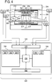
- Fig. 6 shows an example of a coil assembly 600 outside the scope of the invention. Again this coil assembly has a first surface 514 and a second surface 516. The first surface is intended to be directed towards an imaging zone of a magnetic resonance imaging system.
- Within the coil assembly 600 there is a collection of coil elements 317. Each of the coil elements 317 is connected to its own individual matching network element 602. The matching network element 602 is connected to a connection to a transceiver 604. Alternatively they may each be connected to a transmitter or receiver also. There may be a separate connection from each matching network element 602 to the transceiver, transmitter, or receiver.
- Also within the coil assembly 600 there is a collection of conductive elements 322 connected by multiple radio-frequency switches 324. The radio-frequency switches 324 are connected to a connection to a radio-frequency shield controller 512.
- the coil elements 317 are between the first surface and the conductive elements 322.
- Embodiments of the invention can easily be realized using common PCB-based coil technology.
- the coil element itself remains unchanged besides the proper tuning compared to the case of no RF-screen present.
- the RF-screen is introduced using typical coil material as well, e.g. copper coated low loss PCB-substrate like FR4.
- the screen is structured e.g. as is shown in Fig. 8 : the slots between the segments in this realization are to be bridged with one or more PIN-diodes in a suitable fashion.
- the diodes are forward biased during transmit shortening the slots and thus forming one RF-screen from the different patches.
- the PIN-diodes are reverse biased isolating the patches from one another. Size and number of patches necessary for a given frequency and coil geometry have to be adapted on case by case basis.
- Fig. 16 illustrates how an embodiment of the invention may be used to protect a portion of a subject 1608.
- a subject 1600 is shown, the subject 1600 is adjacent to a receive coil segment 602.
- the receive coil segment 602 is between the subject and a transmit coil segment 1604.
- On the opposite side of the transmit coil segment 1604 from the receive coil segment 1602 is located a switchable radio-frequency screen 1606.
- the switchable radio-frequency screen 1606 is located between a portion of the subject 1608 and the transmit coil segment 1604.
- the switchable radio-frequency screen 1606 is switched into the closed or blocking state radiation 1610 from the transmit coil segment 1604 is blocked from reaching the shielded portion of the subject 1608.
- Fig. 18 shows an alternative arrangement of the conductive elements 322.
- a radio-frequency shield 1800 is formed by 16 square conductive elements 322.
- Fig. 20 shows an alternative embodiment of a radio-frequency shield 2000 according to an embodiment of the invention.
- the conductive elements 322 are arranged in a target-shape.
- Fig. 21 illustrates how the radio-frequency shield could be constructed using patterned printed circuit board 2100.
- Two pieces of patterned printed circuit board 21 are shown. Each one consists of a low loss substrate 2102. Attached to the low loss substrate 2102 on each board 2100 is patterned copper 2104. Such copper strips 2104 could be used for constructing the antenna elements and/or the conductive elements for the coil assembly.
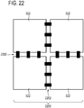
- Fig. 22 shows an alternative embodiment of a radio-frequency shield 2200 according to an embodiment of the invention.
- the conductive elements are connected together with rows of pin diodes 2202.
- the pin diodes 2202 function as the radio-frequency switches.
- This example could be constructed using a printed circuit board with example pin diodes for switching on and off.
- the switches may be replaced by or accompanied by lumped components like capacitors for further expanding the tuning possibilities of the radio-frequency shield 2200.
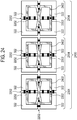
- Fig. 25 shows an alternative example of a coil assembly 2500 outside the scope of the invention.
- the example of Fig. 25 is similar to that in Figs. 24 and 23 .
- the TEM coil or butterfly coil has been replaced with a loop coil 2502.
- the switchable radio-frequency screen 2704 is between the electronic components 2706 and the coil elements 2702. In case the coil elements 2702 are used to broadcast or transmit radio-frequency energy the switchable radio-frequency screen 2704 can be put into a closed or blocking state in order to protect the electronic components 2706.
- the radio-frequency coils are not decoupled and may have separate switchable radio-frequency screens.
- An electronic component or device such as an S/R switch, preamplifiers, a local radio-frequency amplifier, a PET or positron emission tomography detector is located above the screen.
- a switchable screen protects the electronics during transmit. In case of a geometrical decoupling of the coils for example there is a via overlap, a suitable screen design could be more evolved.
- Embodiments of the invention may have one or more of the following features, provided that the resulting subject-matter falls within the scope of the appended claims:
Landscapes
- Physics & Mathematics (AREA)
- Health & Medical Sciences (AREA)
- Epidemiology (AREA)
- Condensed Matter Physics & Semiconductors (AREA)
- General Physics & Mathematics (AREA)
- Magnetic Resonance Imaging Apparatus (AREA)
Applications Claiming Priority (2)
| Application Number | Priority Date | Filing Date | Title |
|---|---|---|---|
| US201161548287P | 2011-10-18 | 2011-10-18 | |
| PCT/IB2012/055289 WO2013057612A1 (en) | 2011-10-18 | 2012-10-03 | Mri coil assembly with a radio frequency shield switchable between a blocking state and a transparent state |
Publications (2)
| Publication Number | Publication Date |
|---|---|
| EP2745132A1 EP2745132A1 (en) | 2014-06-25 |
| EP2745132B1 true EP2745132B1 (en) | 2020-12-09 |
Family
ID=47192031
Family Applications (1)
| Application Number | Title | Priority Date | Filing Date |
|---|---|---|---|
| EP12787879.1A Active EP2745132B1 (en) | 2011-10-18 | 2012-10-03 | Mri coil assembly with a radio frequency shield switchable between a blocking state and a transparent state |
Country Status (8)
| Country | Link |
|---|---|
| US (1) | US9869735B2 (https=) |
| EP (1) | EP2745132B1 (https=) |
| JP (1) | JP6033320B2 (https=) |
| CN (1) | CN103959085B (https=) |
| IN (1) | IN2014CN02544A (https=) |
| MX (1) | MX2014004533A (https=) |
| RU (1) | RU2595798C2 (https=) |
| WO (1) | WO2013057612A1 (https=) |
Families Citing this family (22)
| Publication number | Priority date | Publication date | Assignee | Title |
|---|---|---|---|---|
| DE102012203331B4 (de) * | 2012-03-02 | 2015-08-27 | Siemens Aktiengesellschaft | Lokalschirm und Verfahren zur Abschirmung von Magnetresonanzsignalen |
| EP2672286A1 (en) * | 2012-06-05 | 2013-12-11 | Koninklijke Philips N.V. | TEM resonator system especially for use in an MRI system |
| WO2014068448A1 (en) * | 2012-11-05 | 2014-05-08 | Koninklijke Philips N.V. | Transmit/receive switching circuitry with improved radio frequency isolation |
| WO2014202552A1 (en) * | 2013-06-17 | 2014-12-24 | Koninklijke Philips N.V. | Magnetic resonance imaging subject support |
| EP3080635A1 (en) * | 2013-12-10 | 2016-10-19 | Koninklijke Philips N.V. | Calculating mri rf coil sensitivities using interpolation into an enlarged field of view |
| DE102014207843B4 (de) * | 2014-04-25 | 2019-06-27 | Siemens Healthcare Gmbh | Knie-Spule |
| US10172575B2 (en) * | 2014-09-16 | 2019-01-08 | Koninklijke Philips N.V. | Protection system for protecting a person against X-ray scatter radiation |
| DE102015201462B3 (de) * | 2015-01-28 | 2016-05-12 | Siemens Aktiengesellschaft | Hochfrequenz-Spuleneinheit für eine Magnetresonanz-Bildgebung |
| EP3523666B1 (en) * | 2016-10-10 | 2022-04-27 | Koninklijke Philips N.V. | Co-planar rf coil feeding |
| DE102017214088A1 (de) * | 2017-08-11 | 2019-02-14 | Siemens Healthcare Gmbh | Bilddatenerzeugung in einem Untersuchungsraum einer MR-Anlage |
| US11564575B2 (en) | 2018-01-17 | 2023-01-31 | Shanghai United Imaging Healthcare Co., Ltd. | Magnetic resonance-positron emission tomography imaging apparatus |
| CN108761365B (zh) * | 2018-04-11 | 2021-02-19 | 上海联影医疗科技股份有限公司 | 屏蔽壳、屏蔽壳的制造方法、pet探测器和系统 |
| US10598739B2 (en) * | 2018-06-18 | 2020-03-24 | Allegro Microsystems, Llc | Magnetic field sensors having virtual signals |
| US10866118B2 (en) | 2018-06-18 | 2020-12-15 | Allegro Microsystems, Llc | High resolution magnetic field sensors |
| US10908229B2 (en) | 2018-06-18 | 2021-02-02 | Allegro Microsystems, Llc | Regulation of coefficients used in magnetic field sensor virtual signal generation |
| US10578679B2 (en) * | 2018-06-18 | 2020-03-03 | Allegro Microsystems, Llc | Magnetic field sensors having virtual signals |
| US10684336B2 (en) | 2018-10-24 | 2020-06-16 | General Electric Company | Radiofrequency coil and shield in magnetic resonance imaging method and apparatus |
| US10859648B2 (en) * | 2019-04-01 | 2020-12-08 | GE Precision Healthcare LLC | Systems and methods for a configurable radio frequency coil for MR imaging |
| US11460525B2 (en) * | 2020-02-12 | 2022-10-04 | GE Precision Healthcare LLC | Systems and methods for toroidal twinax cable trap |
| CN111965577B (zh) * | 2020-07-07 | 2023-07-28 | 无锡鸣石峻致医疗科技有限公司 | 一种多频线圈 |
| CN112540332B (zh) * | 2020-12-03 | 2023-11-14 | 深圳航天科技创新研究院 | 一种磁共振射频屏蔽结构及其设计方法 |
| US11762043B2 (en) | 2021-03-11 | 2023-09-19 | Allegro Microsystems, Llc | High resolution magnetic field sensors |
Family Cites Families (26)
| Publication number | Priority date | Publication date | Assignee | Title |
|---|---|---|---|---|
| CN1009140B (zh) * | 1985-04-01 | 1990-08-08 | 菲利浦光灯制造公司 | 产生和/或接收交变磁场的射频线圈系统 |
| JPH0349737A (ja) * | 1989-07-18 | 1991-03-04 | Toshiba Corp | 磁気共鳴イメージング装置 |
| US5132621A (en) * | 1990-04-24 | 1992-07-21 | General Electric Company | Radio frequency field coil and power splitter for nmr |
| US5406204A (en) | 1992-03-27 | 1995-04-11 | Picker International, Inc. | Integrated MRI gradient coil and RF screen |
| JPH07155307A (ja) * | 1993-12-09 | 1995-06-20 | Hitachi Ltd | Mri用rfコイルおよびmri装置 |
| US5419325A (en) * | 1994-06-23 | 1995-05-30 | General Electric Company | Magnetic resonance (MR) angiography using a faraday catheter |
| JP3492009B2 (ja) * | 1995-03-16 | 2004-02-03 | ジーイー横河メディカルシステム株式会社 | Mri用コイル装置 |
| US5808467A (en) * | 1995-05-31 | 1998-09-15 | Hitachi, Ltd. | RF probe and inspection system using NMR using the same |
| US5760584A (en) * | 1996-08-16 | 1998-06-02 | General Electric Company | Shield for MR system RF coil provided with multiple capacitive channels for RF current flow |
| JPH11299754A (ja) * | 1998-04-23 | 1999-11-02 | Toshiba Iyo System Engineering Kk | Mri装置用分割型rfコイル |
| JP3457537B2 (ja) * | 1998-06-30 | 2003-10-20 | 株式会社東芝 | 磁気共鳴映像装置 |
| US6437567B1 (en) * | 1999-12-06 | 2002-08-20 | General Electric Company | Radio frequency coil for open magnetic resonance imaging system |
| GB2360094A (en) * | 2000-03-06 | 2001-09-12 | Marconi Caswell Ltd | RF screens for MRI |
| US6522144B2 (en) | 2000-12-22 | 2003-02-18 | Ge Medical Systems Global Technology Company, Llc | RF shielding method and apparatus for an open MRI system |
| US6498947B2 (en) | 2001-02-23 | 2002-12-24 | Ge Medical Systems Global Technology Company, Llc | rf shielding method and apparatus |
| US20050107681A1 (en) * | 2003-07-23 | 2005-05-19 | Griffiths David M. | Wireless patient monitoring device for magnetic resonance imaging |
| US7053617B2 (en) | 2003-10-01 | 2006-05-30 | General Electric Co. | Integrated electronic RF shielding apparatus for an MRI magnet |
| WO2005050239A1 (en) * | 2003-11-18 | 2005-06-02 | Koninklijke Philips Electronics, N.V. | Rf coil system for super high field (shf) mri |
| JP2006346055A (ja) * | 2005-06-15 | 2006-12-28 | Hitachi Medical Corp | 磁気共鳴を用いた検査装置 |
| JP2007260078A (ja) * | 2006-03-28 | 2007-10-11 | Ge Medical Systems Global Technology Co Llc | Rfコイル及び磁気共鳴撮像装置 |
| WO2008078284A2 (en) * | 2006-12-22 | 2008-07-03 | Koninklijke Philips Electronics N.V. | Rf coil for use in an mr imaging system, in combination with a metamaterial |
| EP2620783A1 (en) * | 2007-02-26 | 2013-07-31 | Koninklijke Philips Electronics N.V. | Doubly resonant high field radio frequency surface coils for magnetic resonance |
| JP5103640B2 (ja) * | 2007-04-13 | 2012-12-19 | 株式会社日立メディコ | 磁気共鳴イメージング装置 |
| JP5247214B2 (ja) | 2008-04-04 | 2013-07-24 | 株式会社日立製作所 | 高周波磁場コイル及び磁気共鳴撮影装置 |
| DE102008063457B3 (de) * | 2008-12-17 | 2010-06-02 | Siemens Aktiengesellschaft | Lokalspulenanordnung für Magnetresonanzanwendungen mit aktivierbarem Marker |
| CN102652027B (zh) | 2009-12-10 | 2014-11-26 | 皇家飞利浦电子股份有限公司 | 具有射频屏蔽或外罩的磁共振兼容电子装置 |
-
2012
- 2012-10-03 RU RU2014119865/28A patent/RU2595798C2/ru active
- 2012-10-03 IN IN2544CHN2014 patent/IN2014CN02544A/en unknown
- 2012-10-03 EP EP12787879.1A patent/EP2745132B1/en active Active
- 2012-10-03 CN CN201280051019.8A patent/CN103959085B/zh active Active
- 2012-10-03 US US14/352,030 patent/US9869735B2/en active Active
- 2012-10-03 WO PCT/IB2012/055289 patent/WO2013057612A1/en not_active Ceased
- 2012-10-03 JP JP2014536357A patent/JP6033320B2/ja active Active
- 2012-10-03 MX MX2014004533A patent/MX2014004533A/es not_active Application Discontinuation
Non-Patent Citations (1)
| Title |
|---|
| None * |
Also Published As
| Publication number | Publication date |
|---|---|
| RU2014119865A (ru) | 2015-11-27 |
| US9869735B2 (en) | 2018-01-16 |
| WO2013057612A1 (en) | 2013-04-25 |
| IN2014CN02544A (https=) | 2015-07-31 |
| EP2745132A1 (en) | 2014-06-25 |
| CN103959085A (zh) | 2014-07-30 |
| JP6033320B2 (ja) | 2016-11-30 |
| US20140253122A1 (en) | 2014-09-11 |
| MX2014004533A (es) | 2014-08-01 |
| RU2595798C2 (ru) | 2016-08-27 |
| CN103959085B (zh) | 2017-03-08 |
| JP2014530079A (ja) | 2014-11-17 |
Similar Documents
| Publication | Publication Date | Title |
|---|---|---|
| EP2745132B1 (en) | Mri coil assembly with a radio frequency shield switchable between a blocking state and a transparent state | |
| KR100677021B1 (ko) | Rf바디 코일 | |
| EP3523667B1 (en) | Impedance matching using multiple rf ports | |
| US9116214B2 (en) | RF coil array having two or more switches built within each RF coil array element, compatible with both magnetic resonance and a temperature mapping | |
| EP3123189B1 (en) | Magnetic resonance imaging rf antenna | |
| WO2010045457A2 (en) | Coil element decoupling for mri | |
| US10877116B2 (en) | Birdcage magnetic resonance imaging (MRI) coil with open shield for single tune MRI coil and multi-tune MRI coil | |
| Zhang et al. | Effect of radiofrequency shield diameter on signal‐to‐noise ratio at ultra‐high field MRI | |
| Woo et al. | A monopole and dipole hybrid antenna array for human brain imaging at 10.5 Tesla | |
| Kowal et al. | Impact of unit cell density on grid and stripe metasurfaces for MRI receive enhancement | |
| EP2856194B1 (en) | System of tem resonators for use in an mri system | |
| Ruytenberg et al. | Design of a dielectric resonator receive array at 7 Tesla using detunable ceramic resonators | |
| US20100109667A1 (en) | Transverse electromagnetic radio-frequency coil | |
| WO2017050605A1 (en) | Radio frequency antenna assembly for magnetic resonance image guided therapy | |
| Nikulin et al. | Reconfigurable dipole receive array for dynamic parallel imaging at ultra‐high magnetic field | |
| US10444312B2 (en) | Magnetic resonance imaging system | |
| US8436615B2 (en) | Detunable waveguide antenna assembly | |
| EP3387456B1 (en) | Radio frequency coil-array for magnetic resonance examination system | |
| Vaughan | Ultra high field MRI: High-frequency coils | |
| EP4303604B1 (en) | Receiving coil | |
| Nowikow et al. | Network and Field Analysis of Koch Snowflake Fractal Geometry Radiofrequency Coils for Sodium MRI | |
| Nafi et al. | Double-Sided Individually Shielded Monopole Antenna Array Design for Ultra High Field (UHF) MRI | |
| US12436214B2 (en) | Field modification device | |
| AUSSENHOFER | IMAGING AT 7.0 TESLA. | |
| WO2005122890A1 (ja) | Mr装置用ボリュームコイル |
Legal Events
| Date | Code | Title | Description |
|---|---|---|---|
| PUAI | Public reference made under article 153(3) epc to a published international application that has entered the european phase |
Free format text: ORIGINAL CODE: 0009012 |
|
| 17P | Request for examination filed |
Effective date: 20140319 |
|
| AK | Designated contracting states |
Kind code of ref document: A1 Designated state(s): AL AT BE BG CH CY CZ DE DK EE ES FI FR GB GR HR HU IE IS IT LI LT LU LV MC MK MT NL NO PL PT RO RS SE SI SK SM TR |
|
| DAX | Request for extension of the european patent (deleted) | ||
| RAP1 | Party data changed (applicant data changed or rights of an application transferred) |
Owner name: PHILIPS GMBH Owner name: KONINKLIJKE PHILIPS N.V. |
|
| RAP1 | Party data changed (applicant data changed or rights of an application transferred) |
Owner name: PHILIPS GMBH Owner name: KONINKLIJKE PHILIPS N.V. |
|
| GRAP | Despatch of communication of intention to grant a patent |
Free format text: ORIGINAL CODE: EPIDOSNIGR1 |
|
| STAA | Information on the status of an ep patent application or granted ep patent |
Free format text: STATUS: GRANT OF PATENT IS INTENDED |
|
| INTG | Intention to grant announced |
Effective date: 20200625 |
|
| GRAS | Grant fee paid |
Free format text: ORIGINAL CODE: EPIDOSNIGR3 |
|
| GRAA | (expected) grant |
Free format text: ORIGINAL CODE: 0009210 |
|
| STAA | Information on the status of an ep patent application or granted ep patent |
Free format text: STATUS: THE PATENT HAS BEEN GRANTED |
|
| AK | Designated contracting states |
Kind code of ref document: B1 Designated state(s): AL AT BE BG CH CY CZ DE DK EE ES FI FR GB GR HR HU IE IS IT LI LT LU LV MC MK MT NL NO PL PT RO RS SE SI SK SM TR |
|
| REG | Reference to a national code |
Ref country code: GB Ref legal event code: FG4D |
|
| REG | Reference to a national code |
Ref country code: AT Ref legal event code: REF Ref document number: 1343979 Country of ref document: AT Kind code of ref document: T Effective date: 20201215 Ref country code: CH Ref legal event code: EP |
|
| REG | Reference to a national code |
Ref country code: DE Ref legal event code: R096 Ref document number: 602012073656 Country of ref document: DE |
|
| REG | Reference to a national code |
Ref country code: IE Ref legal event code: FG4D |
|
| REG | Reference to a national code |
Ref country code: DE Ref legal event code: R084 Ref document number: 602012073656 Country of ref document: DE |
|
| REG | Reference to a national code |
Ref country code: GB Ref legal event code: 746 Effective date: 20210202 |
|
| PG25 | Lapsed in a contracting state [announced via postgrant information from national office to epo] |
Ref country code: GR Free format text: LAPSE BECAUSE OF FAILURE TO SUBMIT A TRANSLATION OF THE DESCRIPTION OR TO PAY THE FEE WITHIN THE PRESCRIBED TIME-LIMIT Effective date: 20210310 Ref country code: RS Free format text: LAPSE BECAUSE OF FAILURE TO SUBMIT A TRANSLATION OF THE DESCRIPTION OR TO PAY THE FEE WITHIN THE PRESCRIBED TIME-LIMIT Effective date: 20201209 Ref country code: FI Free format text: LAPSE BECAUSE OF FAILURE TO SUBMIT A TRANSLATION OF THE DESCRIPTION OR TO PAY THE FEE WITHIN THE PRESCRIBED TIME-LIMIT Effective date: 20201209 Ref country code: NO Free format text: LAPSE BECAUSE OF FAILURE TO SUBMIT A TRANSLATION OF THE DESCRIPTION OR TO PAY THE FEE WITHIN THE PRESCRIBED TIME-LIMIT Effective date: 20210309 |
|
| REG | Reference to a national code |
Ref country code: AT Ref legal event code: MK05 Ref document number: 1343979 Country of ref document: AT Kind code of ref document: T Effective date: 20201209 |
|
| PG25 | Lapsed in a contracting state [announced via postgrant information from national office to epo] |
Ref country code: BG Free format text: LAPSE BECAUSE OF FAILURE TO SUBMIT A TRANSLATION OF THE DESCRIPTION OR TO PAY THE FEE WITHIN THE PRESCRIBED TIME-LIMIT Effective date: 20210309 Ref country code: SE Free format text: LAPSE BECAUSE OF FAILURE TO SUBMIT A TRANSLATION OF THE DESCRIPTION OR TO PAY THE FEE WITHIN THE PRESCRIBED TIME-LIMIT Effective date: 20201209 Ref country code: LV Free format text: LAPSE BECAUSE OF FAILURE TO SUBMIT A TRANSLATION OF THE DESCRIPTION OR TO PAY THE FEE WITHIN THE PRESCRIBED TIME-LIMIT Effective date: 20201209 |
|
| REG | Reference to a national code |
Ref country code: NL Ref legal event code: MP Effective date: 20201209 |
|
| PG25 | Lapsed in a contracting state [announced via postgrant information from national office to epo] |
Ref country code: NL Free format text: LAPSE BECAUSE OF FAILURE TO SUBMIT A TRANSLATION OF THE DESCRIPTION OR TO PAY THE FEE WITHIN THE PRESCRIBED TIME-LIMIT Effective date: 20201209 Ref country code: HR Free format text: LAPSE BECAUSE OF FAILURE TO SUBMIT A TRANSLATION OF THE DESCRIPTION OR TO PAY THE FEE WITHIN THE PRESCRIBED TIME-LIMIT Effective date: 20201209 |
|
| REG | Reference to a national code |
Ref country code: LT Ref legal event code: MG9D |
|
| PG25 | Lapsed in a contracting state [announced via postgrant information from national office to epo] |
Ref country code: RO Free format text: LAPSE BECAUSE OF FAILURE TO SUBMIT A TRANSLATION OF THE DESCRIPTION OR TO PAY THE FEE WITHIN THE PRESCRIBED TIME-LIMIT Effective date: 20201209 Ref country code: PT Free format text: LAPSE BECAUSE OF FAILURE TO SUBMIT A TRANSLATION OF THE DESCRIPTION OR TO PAY THE FEE WITHIN THE PRESCRIBED TIME-LIMIT Effective date: 20210409 Ref country code: SK Free format text: LAPSE BECAUSE OF FAILURE TO SUBMIT A TRANSLATION OF THE DESCRIPTION OR TO PAY THE FEE WITHIN THE PRESCRIBED TIME-LIMIT Effective date: 20201209 Ref country code: LT Free format text: LAPSE BECAUSE OF FAILURE TO SUBMIT A TRANSLATION OF THE DESCRIPTION OR TO PAY THE FEE WITHIN THE PRESCRIBED TIME-LIMIT Effective date: 20201209 Ref country code: SM Free format text: LAPSE BECAUSE OF FAILURE TO SUBMIT A TRANSLATION OF THE DESCRIPTION OR TO PAY THE FEE WITHIN THE PRESCRIBED TIME-LIMIT Effective date: 20201209 Ref country code: CZ Free format text: LAPSE BECAUSE OF FAILURE TO SUBMIT A TRANSLATION OF THE DESCRIPTION OR TO PAY THE FEE WITHIN THE PRESCRIBED TIME-LIMIT Effective date: 20201209 Ref country code: EE Free format text: LAPSE BECAUSE OF FAILURE TO SUBMIT A TRANSLATION OF THE DESCRIPTION OR TO PAY THE FEE WITHIN THE PRESCRIBED TIME-LIMIT Effective date: 20201209 |
|
| PG25 | Lapsed in a contracting state [announced via postgrant information from national office to epo] |
Ref country code: PL Free format text: LAPSE BECAUSE OF FAILURE TO SUBMIT A TRANSLATION OF THE DESCRIPTION OR TO PAY THE FEE WITHIN THE PRESCRIBED TIME-LIMIT Effective date: 20201209 Ref country code: AT Free format text: LAPSE BECAUSE OF FAILURE TO SUBMIT A TRANSLATION OF THE DESCRIPTION OR TO PAY THE FEE WITHIN THE PRESCRIBED TIME-LIMIT Effective date: 20201209 |
|
| REG | Reference to a national code |
Ref country code: DE Ref legal event code: R097 Ref document number: 602012073656 Country of ref document: DE |
|
| PG25 | Lapsed in a contracting state [announced via postgrant information from national office to epo] |
Ref country code: IS Free format text: LAPSE BECAUSE OF FAILURE TO SUBMIT A TRANSLATION OF THE DESCRIPTION OR TO PAY THE FEE WITHIN THE PRESCRIBED TIME-LIMIT Effective date: 20210409 |
|
| PLBE | No opposition filed within time limit |
Free format text: ORIGINAL CODE: 0009261 |
|
| STAA | Information on the status of an ep patent application or granted ep patent |
Free format text: STATUS: NO OPPOSITION FILED WITHIN TIME LIMIT |
|
| PG25 | Lapsed in a contracting state [announced via postgrant information from national office to epo] |
Ref country code: AL Free format text: LAPSE BECAUSE OF FAILURE TO SUBMIT A TRANSLATION OF THE DESCRIPTION OR TO PAY THE FEE WITHIN THE PRESCRIBED TIME-LIMIT Effective date: 20201209 Ref country code: IT Free format text: LAPSE BECAUSE OF FAILURE TO SUBMIT A TRANSLATION OF THE DESCRIPTION OR TO PAY THE FEE WITHIN THE PRESCRIBED TIME-LIMIT Effective date: 20201209 |
|
| 26N | No opposition filed |
Effective date: 20210910 |
|
| PG25 | Lapsed in a contracting state [announced via postgrant information from national office to epo] |
Ref country code: SI Free format text: LAPSE BECAUSE OF FAILURE TO SUBMIT A TRANSLATION OF THE DESCRIPTION OR TO PAY THE FEE WITHIN THE PRESCRIBED TIME-LIMIT Effective date: 20201209 Ref country code: ES Free format text: LAPSE BECAUSE OF FAILURE TO SUBMIT A TRANSLATION OF THE DESCRIPTION OR TO PAY THE FEE WITHIN THE PRESCRIBED TIME-LIMIT Effective date: 20201209 Ref country code: DK Free format text: LAPSE BECAUSE OF FAILURE TO SUBMIT A TRANSLATION OF THE DESCRIPTION OR TO PAY THE FEE WITHIN THE PRESCRIBED TIME-LIMIT Effective date: 20201209 |
|
| REG | Reference to a national code |
Ref country code: CH Ref legal event code: PL |
|
| PG25 | Lapsed in a contracting state [announced via postgrant information from national office to epo] |
Ref country code: IS Free format text: LAPSE BECAUSE OF FAILURE TO SUBMIT A TRANSLATION OF THE DESCRIPTION OR TO PAY THE FEE WITHIN THE PRESCRIBED TIME-LIMIT Effective date: 20210409 |
|
| REG | Reference to a national code |
Ref country code: BE Ref legal event code: MM Effective date: 20211031 |
|
| PG25 | Lapsed in a contracting state [announced via postgrant information from national office to epo] |
Ref country code: MC Free format text: LAPSE BECAUSE OF FAILURE TO SUBMIT A TRANSLATION OF THE DESCRIPTION OR TO PAY THE FEE WITHIN THE PRESCRIBED TIME-LIMIT Effective date: 20201209 |
|
| PG25 | Lapsed in a contracting state [announced via postgrant information from national office to epo] |
Ref country code: LU Free format text: LAPSE BECAUSE OF NON-PAYMENT OF DUE FEES Effective date: 20211003 Ref country code: BE Free format text: LAPSE BECAUSE OF NON-PAYMENT OF DUE FEES Effective date: 20211031 |
|
| PG25 | Lapsed in a contracting state [announced via postgrant information from national office to epo] |
Ref country code: LI Free format text: LAPSE BECAUSE OF NON-PAYMENT OF DUE FEES Effective date: 20211031 Ref country code: CH Free format text: LAPSE BECAUSE OF NON-PAYMENT OF DUE FEES Effective date: 20211031 |
|
| PG25 | Lapsed in a contracting state [announced via postgrant information from national office to epo] |
Ref country code: IE Free format text: LAPSE BECAUSE OF NON-PAYMENT OF DUE FEES Effective date: 20211003 |
|
| PG25 | Lapsed in a contracting state [announced via postgrant information from national office to epo] |
Ref country code: HU Free format text: LAPSE BECAUSE OF FAILURE TO SUBMIT A TRANSLATION OF THE DESCRIPTION OR TO PAY THE FEE WITHIN THE PRESCRIBED TIME-LIMIT; INVALID AB INITIO Effective date: 20121003 Ref country code: CY Free format text: LAPSE BECAUSE OF FAILURE TO SUBMIT A TRANSLATION OF THE DESCRIPTION OR TO PAY THE FEE WITHIN THE PRESCRIBED TIME-LIMIT Effective date: 20201209 |
|
| PG25 | Lapsed in a contracting state [announced via postgrant information from national office to epo] |
Ref country code: MK Free format text: LAPSE BECAUSE OF FAILURE TO SUBMIT A TRANSLATION OF THE DESCRIPTION OR TO PAY THE FEE WITHIN THE PRESCRIBED TIME-LIMIT Effective date: 20201209 |
|
| PG25 | Lapsed in a contracting state [announced via postgrant information from national office to epo] |
Ref country code: MT Free format text: LAPSE BECAUSE OF FAILURE TO SUBMIT A TRANSLATION OF THE DESCRIPTION OR TO PAY THE FEE WITHIN THE PRESCRIBED TIME-LIMIT Effective date: 20201209 |
|
| PG25 | Lapsed in a contracting state [announced via postgrant information from national office to epo] |
Ref country code: TR Free format text: LAPSE BECAUSE OF FAILURE TO SUBMIT A TRANSLATION OF THE DESCRIPTION OR TO PAY THE FEE WITHIN THE PRESCRIBED TIME-LIMIT Effective date: 20201209 |
|
| PGFP | Annual fee paid to national office [announced via postgrant information from national office to epo] |
Ref country code: DE Payment date: 20251028 Year of fee payment: 14 |
|
| PGFP | Annual fee paid to national office [announced via postgrant information from national office to epo] |
Ref country code: GB Payment date: 20251023 Year of fee payment: 14 |
|
| PGFP | Annual fee paid to national office [announced via postgrant information from national office to epo] |
Ref country code: FR Payment date: 20251027 Year of fee payment: 14 |