EP2744688B1 - Toilette für fahrzeuge, insbesondere für busse, reisemobile, caravans und yachten - Google Patents
Toilette für fahrzeuge, insbesondere für busse, reisemobile, caravans und yachten Download PDFInfo
- Publication number
- EP2744688B1 EP2744688B1 EP12748015.0A EP12748015A EP2744688B1 EP 2744688 B1 EP2744688 B1 EP 2744688B1 EP 12748015 A EP12748015 A EP 12748015A EP 2744688 B1 EP2744688 B1 EP 2744688B1
- Authority
- EP
- European Patent Office
- Prior art keywords
- toilet
- toilet bowl
- holder
- sealing
- sealing ring
- Prior art date
- Legal status (The legal status is an assumption and is not a legal conclusion. Google has not performed a legal analysis and makes no representation as to the accuracy of the status listed.)
- Active
Links
Images



Classifications
-
- B—PERFORMING OPERATIONS; TRANSPORTING
- B60—VEHICLES IN GENERAL
- B60R—VEHICLES, VEHICLE FITTINGS, OR VEHICLE PARTS, NOT OTHERWISE PROVIDED FOR
- B60R15/00—Arrangements or adaptations of sanitation devices
- B60R15/04—Toilet facilities
Definitions
- the invention relates to a toilet for vehicles, in particular for buses, motorhomes, caravans and yachts, which has a toilet bowl, wherein the toilet bowl is held in the region of a lower opening of a holder.
- Such toilets are known in the art. For example, goes from the DE 20 2007 002 270 U1 a toilet system for installation in a vehicle, in which a toilet bowl is rotatably mounted on a base. Liquids and solids can be transferred through the lower opening into a tank in the base.
- a disadvantage of the known toilets has been found that the toilet bowl is pressed to clamp from above into a holder. This leads to high internal voltages in the toilet bowl, which can lead to cracks. By vibrations and vibrations, z. B. by vehicle movements, it comes so quickly to damage the toilet bowl.
- the publication EP 0 940 510 A1 shows a toilet with the features of the preamble of claim 1.
- the toilet bowl has no fastener that is fixed to the toilet bowl and is connected to a bracket.
- relative movements between toilet bowl can occur on the holder and liquid can enter at the bottom of the toilet bowl between toilet bowl and bracket.
- a sealing element is arranged between the toilet bowl and the holder.
- a particularly advantageous sealing compound consisting of toilet bowl, sealing element and holder.
- the sealing element in this case has both a compensatory and a sealing function.
- the toilet can be specifically manufactured and produced to the exact sealing point.
- the holder is easy to reproduce and allows greater manufacturing tolerances.
- the toilet parts, especially the bowl and gasket, are easily interchangeable.
- the toilet is therefore service and spare parts friendly.
- a relatively simple plastic toilet bowl can be replaced with a ceramic, glass or metal toilet bowl.
- the joining geometry can be injection-molded onto a plastic bowl. Thus, it is possible to obstruct a variety of toilet bowls in the toilet according to the invention.
- the sealing element is a sealing ring.
- Such sealing rings may contain an elastomer.
- a sealing ring can be used flexibly and exchanged as well as reusable.
- a known sealing ring may have two legs between which there is an angle. Thus, it is possible to enclose and support the toilet bowl, for example, in the vertical and horizontal directions.
- the sealing surface is increased so advantageous and improves the tightness.
- a leg of the known sealing ring may be formed in cross-section Y-shaped. By this design, the pressure on the adjacent sealing surfaces is increased in the installed state. Preferably, a horizontal leg is formed in this way.
- a rib is provided on one leg.
- the rib may preferably extend in the radial direction towards the toilet bowl. It can also be provided a plurality of ribs spaced from each other. The ribs allow compensation in the horizontal direction. In addition, individual chambers are created that enhance the sealing effect.
- a leg of the known sealing ring on a bead Due to the bead, the sealing ring can be clamped between a plurality of sealing surfaces.
- a leg of the known sealing ring has the shape of a foot. Due to the arcuate design larger vertical tolerances can be compensated.
- the known sealing ring is fastened to the toilet bowl via a fixing element.
- fixing elements are closing clips, spring band clamps, ear collars (also with adjustable tension or closing force), threaded hose clamps or cable ties into consideration.
- One leg of the sealing ring has a circumferential groove for the fixing element. In this way, the fixing element is securely guided, even before it is tightened.
- the well-known sealing ring in cross-section T-shaped. Two legs of the sealing ring can then surround the toilet bowl and the third leg can be used to fix the sealing ring in the holder, preferably by clamping. On the cross-sectionally T-shaped sealing ring, a further sealing lip can also be attached to the junction of the legs of the sealing ring.
- the known sealing ring is fixed via a clamping element on the holder, wherein the clamping element is preferably clipped into the holder or screwed to the holder.
- the clamping element makes it possible to increase the pressure on the sealing ring or adjust specifically.
- sealing surfaces are formed on the holder and / or the clamping element sealing surfaces for the known sealing ring. These sealing surfaces may in particular be chamfered surfaces.
- a fixing ring is fixed to the toilet bowl, wherein the fixing ring is preferably clipped into the holder, and further preferably, the sealing element between the fixing ring and the holder is arranged.
- the attachment ring is a compensation element. It can be provided in various forms to suit the toilet bowl. The assembly is simplified by this design, since the sealing ring must be placed only on the bracket and then the toilet bowl can be snapped with the glued mounting ring.
- the sealing element may further contain an adhesive.
- the adhesive may be applied to the holder in a joining area. After inserting the toilet bowl, the adhesive can harden until a liquid-tight connection is formed.
- a toilet 1 for vehicles especially for buses, motorhomes, caravans and yachts shown.
- the toilet 1 comprises a base 2 which supports a toilet top 3.
- a toilet bowl 4 is arranged in the toilet shell 3.
- the toilet bowl 4 is held in the region of a lower opening 5 by a holder 6.
- a circumferential sealing element 7 is arranged between the toilet bowl 4 and the holder 6.
- the bracket 6 also forms the panel 8 of the toilet shell 3.
- a mounting ring 10 is fixed with bolts.
- the mounting ring 10 has a flushing channel 12 with openings 13 in order to inject water into the toilet bowl 4 can.
- a vacuum breaker 14 is arranged on the mounting ring 10.
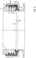
- the holder 6 and a conventional sealing element 7, here a sealing ring 15, are in Fig. 2 shown in detail.
- the sealing ring 15 is inserted into the holder 6 and surrounds the opening 5 at the lower end 16 of the toilet bowl 4.
- the sealing ring 15 is L-shaped in cross-section and has two at right angles to each other ⁇ arranged legs 17, 18.
- the horizontal leg 17 is Y-shaped.
- On the vertical leg 18 three ribs 19-21 are provided which extend in the radial direction to the toilet bowl 4 out.
- a fixing element 22 is placed in the form of a clasp.
- the closure clip 22 is a component of the holder 6. By closing the closure clip 22, a force is introduced into the holder 6, which causes the holder 6 is radially compressed. As a result, a force on the sealing ring 15th exerted, which causes the sealing ring 15 conforms to the toilet bowl 4. In this way, a tight bond between the toilet bowl 4 and the holder 6 is provided.
- a known embodiment of the toilet 31 is shown.
- the sealing ring 32 is fixed between the toilet bowl 33 and the holder 34 and a clamping element 35 in the form of a cladding.
- the clamping element 35 is screwed onto the holder 34 via a thread 36.
- the sealing ring 32 is formed foot-shaped on a leg 37. This leg 37 is curved in an arc.
- the other leg 38 has a bead 39 which rests against sealing surfaces 40-40b on the toilet bowl 33, the holder 34 and the clamping element 35.
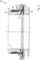
- Fig. 4 shows a known embodiment of the toilet 41 with a sealing ring 42 which has a substantially T-shaped cross-section.
- a sealing ring 42 which has a substantially T-shaped cross-section.
- an additional sealing lip 46 is attached, which extends obliquely upwards and in the direction of the toilet bowl 47.
- the radially outer horizontal leg 45 of the sealing ring 42 is fixed by a circumferential clamping element 48 on the holder 45.
- the clamping element 48 is locked in the holder 49.
- the vertical leg 44 of the sealing ring 42 has on the outside a circumferential groove 50. In the groove 50, a fixing element 50a is arranged in the form of a clamp.
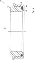
- a fastening ring 54 is fixed with adhesive 55.
- the mounting ring 54 is locked in the holder 56.
- Appropriate locking lugs 57, 58 are provided at the upper ends 59, 60 of mounting ring 54 and bracket 56.
- a sealing element 60c is arranged in the form of a sealing ring.
- Fig. 6 shows a known embodiment of the toilet 61, in which the toilet bowl 62 is inserted into the holder 63.
- an adhesive-containing sealing element 65 is applied circumferentially.
- the adhesive 65 glued in the installed state EZ, the holder 63 and the toilet bowl 62 together liquid-tight.
Landscapes
- Health & Medical Sciences (AREA)
- Epidemiology (AREA)
- General Health & Medical Sciences (AREA)
- Public Health (AREA)
- Engineering & Computer Science (AREA)
- Mechanical Engineering (AREA)
- Sanitary Device For Flush Toilet (AREA)
- Vehicle Waterproofing, Decoration, And Sanitation Devices (AREA)
Description
- Die Erfindung betrifft eine Toilette für Fahrzeuge, insbesondere für Busse, Reisemobile, Caravans und Yachten, die eine Toilettenschüssel aufweist, wobei die Toilettenschüssel im Bereich einer unteren Öffnung von einer Halterung gehalten ist.
- Derartige Toiletten sind im Stand der Technik bekannt. Beispielsweise geht aus der
DE 20 2007 002 270 U1 ein Toilettensystem für den Einbau in ein Fahrzeug hervor, bei dem an einer Basis eine Toilettenschüssel drehbar befestigt ist. Flüssigkeiten und Feststoffe können durch die untere Öffnung in einen Tank in der Basis übergeleitet werden. - Als nachteilig an den bekannten Toiletten hat sich herausgestellt, dass die Toilettenschüssel zum Einspannen von oben in eine Halterung gedrückt wird. Dadurch kommt es zu hohen internen Spannungen in der Toilettenschüssel, die zu Rissen führen können. Durch Vibrationen und Erschütterungen, z. B. durch Fahrzeugbewegungen, kommt es so schnell zu Beschädigungen der Toilettenschüssel.
- Ein weiteres Problem ist, dass der Übergang von der Toilettenschüssel zum Tank nicht direkt erfolgt, sondern dass weitere Bauteile zwischen Toilettenschüssel und Tank angeordnet sind. Der Übergang muss deshalb flüssigkeitsdicht gestaltet sein.
- Die Druckschrift
EP 0 940 510 A1 zeigt eine Toilette mit den Merkmalen des Oberbegriffs von Anspruch 1. Die Toilettenschüssel weist jedoch kein Befestigungselement auf, das an der Toilettenschüssel fixiert ist und mit einer Halterung verbunden ist. Somit können Relativbewegungen zwischen Toilettenschüssel an der Halterung auftreten und Flüssigkeit kann am unteren Rand der Toilettenschüssel zwischen Toilettenschüssel und Halterung eintreten. - Es ist daher Aufgabe der Erfindung, eine Toilette für Fahrzeuge aufzuzeigen, bei der die Toilettenschüssel in einfacher Weise sicher und flüssigkeitsdicht an einer Halterung befestigt ist.
- Diese Aufgabe wird durch eine Toilette für Fahrzeuge mit den Merkmalen von Anspruch 1 gelöst. Bevorzugte Ausführungsformen der Erfindung gehen aus den Unteransprüchen 2 bis 3hervor.
- Erfindungsgemäß ist zwischen der Toilettenschüssel und der Halterung ein Dichtelement angeordnet.
- Auf diese Weise wird ein besonders vorteilhafter Dichtverband bestehend aus Toilettenschüssel, Dichtelement und Halterung gebildet. Das Dichtelement hat hierbei sowohl eine ausgleichende als auch eine dichtende Funktion. Mithin ist es möglich, die Toilettenschüssel frei von internen Spannungen zu montieren und zeitgleich den Übergang zum Tank flüssigkeitsdicht abzudichten. Die Toilette kann gezielt bis auf den exakten Dichtpunkt hergestellt und erzeugt werden. Die Halterung ist einfach reproduzierbar und erlaubt größere Fertigungstoleranzen. Die Einzelteile der Toilette, insbesondere die Schüssel und die Dichtung, sind einfach austauschbar. Die Toilette ist mithin service- und ersatzteilfreundlich. Weiterhin ist es möglich, die Toilettenschüssel durch eine höherwertige auszutauschen. Insbesondere kann eine relativ einfache Kunststofftoilettenschüssel gegen eine Keramik-, Glas- oder Metalltoilettenschüssel ausgetauscht werden. Die Fügegeometrie kann an eine Kunststoffschüssel angespritzt werden. Somit ist es möglich, eine Vielzahl von Toilettenschüsseln in der erfindungsgemäßen Toilette zu verbauen.
- Gemäß einer bevorzugten Ausführungsform ist das Dichtelement ein Dichtring. Derartige Dichtringe können einen Elastomer enthalten. Ein Dichtring ist flexibel einsetzbar und austauschbar sowie wieder verwendbar.
- Ein bekannter Dichtring kann zwei Schenkel aufweisen, zwischen denen ein Winkel besteht. Mithin ist es möglich, die Toilettenschüssel beispielsweise in vertikaler und horizontaler Richtung einzufassen und zu haltern. Die Dichtfläche wird so vorteilhaft vergrößert und die Dichtigkeit verbessert.
- Ein Schenkel des bekannten Dichtrings kann im Querschnitt Y-förmig ausgebildet sein. Durch diese Gestaltung wird der Druck auf die anliegenden Dichtflächen im eingebauten Zustand erhöht. Vorzugsweise ist ein horizontaler Schenkel derart ausgebildet.
- Zweckmäßigerweise ist an einem Schenkel eine Rippe vorgesehen. Die Rippe kann sich vorzugsweise in radialer Richtung zur Toilettenschüssel hin erstrecken. Es können auch mehrere Rippen beabstandet von einander vorgesehen sein. Die Rippen ermöglichen einen Ausgleich in horizontaler Richtung. Zudem werden einzelne Kammern geschaffen, die die Dichtwirkung verstärken.
- Besonders weist ein Schenkel des bekannten Dichtrings eine Wulst auf. Durch die Wulst kann der Dichtring zwischen mehreren Dichtflächen eingeklemmt werden.
- In einer Ausführungsform hat ein Schenkel des bekannten Dichtrings die Form eines Fußes. Durch die bogenförmige Gestaltung können größere vertikale Toleranzen ausgeglichen werden.
- Besonders ist der bekannte Dichtring über ein Fixierungselement an der Toilettenschüssel befestigt. Als Fixierungselemente kommen Verschlussschellen, Federbandschellen, Ohrschellen (auch mit einstellbarer Spannungs- oder Schließkraft), Gewinde-Schlauchsschellen oder Kabelbinder in Betracht. Ein Schenkel des Dichtrings weist eine umlaufende Nut für das Fixierungselement auf. Auf diese Weise wird das Fixierungselement sicher geführt, noch bevor es fest angezogen ist.
- Der bekannte Dichtring im Querschnitt T-förmig. Zwei Schenkel des Dichtrings können dann die Toilettenschüssel einfassen und der dritte Schenkel kann dazu benutzt werden, den Dichtring in der Halterung, vorzugsweise klemmend, zu fixieren. Am im Querschnitt T-förmigen Dichtring kann zudem eine weitere Dichtlippe an der Verbindungsstelle der Schenkel des Dichtrings angesetzt sein.
- Zweckmäßigerweise ist der bekannte Dichtring über ein Klemmelement an der Halterung fixiert, wobei das Klemmelement vorzugsweise in die Halterung eingeclipst oder an die Halterung geschraubt ist. Das Klemmelement macht es möglich, den Druck auf den Dichtring zu erhöhen oder gezielt einzustellen.
- Es sind an der Halterung und/oder dem Klemmelement Dichtflächen für den bekannten Dichtring ausgebildet. Diese Dichtflächen können insbesondere angefaste Flächen sein.
- An der bevorzugten Ausführung der Toilette ist an der Toilettenschüssel kann ein Befestigungsring fixiert, wobei der Befestigungsring vorzugsweise in die Halterung eingeclipst ist, und wobei weiter bevorzugt das Dichtelement zwischen dem Befestigungsring und der Halterung angeordnet ist. Der Befestigungsring ist ein Ausgleichselement. Er kann in verschiedenen Formen in Anpassung an die Toilettenschüssel bereitgestellt werden. Die Montage wird durch diese Gestaltung vereinfacht, da der Dichtring nur auf die Halterung aufgelegt werden muss und dann die Toilettenschüssel mit dem angeklebten Befestigungsring eingerastet werden kann.
- Das Dichtelement kann weiterhin einen Klebstoff enthalten. Der Klebstoff kann auf die Halterung in einem Fügebereich aufgetragen sein. Nach Einsetzen der Toilettenschüssel kann der Klebstoff aushärten bis eine flüssigkeitsdichte Verbindung entstanden ist.
- Die Erfindung ist nachfolgend anhand von mehreren in den Figuren dargestellten Ausführungsbeispielen näher erläutert. Es zeigen:
-
Fig. 1 eine Querschnittsdarstellung einer bekannten Toilette; -
Fig. 2 eine Detaildarstellung derFig. 1 im Bereich der Halterung; -
Fig. 3 eine Querschnittsdarstellung einer bekannten Ausführungsform der Toilette; -
Fig. 4 eine Querschnittsdarstellung einer bekannten Ausführungsform der Toilette; -
Fig. 5 eine Querschnittsdarstellung einer bevorzugten Ausführungsform einer erfindungsgemäßen Toilette; und -
Fig. 6 eine Querschnittsdarstellung der bevorzugten Ausführungsform der Toilette. - In den
Fig. 1 und2 ist eine Toilette 1 für Fahrzeuge, insbesondere für Busse, Reisemobile, Caravans und Yachten, gezeigt. Die Toilette 1 umfasst eine Basis 2, die ein Toilettenoberteil 3 stützt. In dem Toilettenoberteil 3 ist eine Toilettenschüssel 4 angeordnet. Die Toilettenschüssel 4 ist im Bereich einer unteren Öffnung 5 von einer Halterung 6 gehalten. Erfindungsgemäß ist zwischen der Toilettenschüssel 4 und der Halterung 6 ein umlaufendes Dichtelement 7 angeordnet. - Die Halterung 6 bildet zugleich die Verkleidung 8 des Toilettenoberteils 3. Auf das obere Ende 9 der Toilettenschüssel 4 ist ein Montagering 10 mit Schraubbolzen befestigt. Der Montagering 10 weist einen Spülkanal 12 mit Öffnungen 13 auf, um Wasser in die Toilettenschüssel 4 spritzen zu können. Auf der in der Bildebene linken Seite ist ein Vakuumbrecher 14 am Montagering 10 angeordnet.
- Die Halterung 6 und ein übliches Dichtelement 7, hier ein Dichtring 15, sind in
Fig. 2 im Detail gezeigt. Der Dichtring 15 ist in die Halterung 6 eingelegt und umgibt die Öffnung 5 am unteren Ende 16 der Toilettenschüssel 4. Der Dichtring 15 ist im Querschnitt L-förmig und weist zwei im rechten Winkel α zueinander angeordnete Schenkel 17, 18 auf. Der horizontale Schenkel 17 ist Y-förmig ausgeführt. Am vertikalen Schenkel 18 sind drei Rippen 19-21 vorgesehen, die sich in radialer Richtung zur Toilettenschüssel 4 hin erstrecken. Um den vertikalen Schenkel 18 ist ein Fixierungselement 22 in Form einer Verschlussschelle gelegt. Die Verschlussschelle 22 ist ein Bestandteil der Halterung 6. Durch Schließen der Verschlussschelle 22 wird eine Kraft in die Halterung 6 eingeleitet, die bewirkt, dass die Halterung 6 radial zusammengedrückt wird. Dadurch wird eine Kraft auf den Dichtring 15 ausgeübt, die dazu führt, dass sich der Dichtring 15 an die Toilettenschüssel 4 anschmiegt. Auf diese Weise wird ein dichter Verbund zwischen der Toilettenschüssel 4 und der Halterung 6 bereitgestellt. - In der
Fig. 3 ist eine bekannte Ausführungsform der Toilette 31 dargestellt. Darin ist der Dichtring 32 zwischen der Toilettenschüssel 33 und der Halterung 34 sowie einem Klemmelement 35 in Form einer Verkleidung fixiert. Das Klemmelement 35 ist dabei auf die Halterung 34 über ein Gewinde 36 aufgeschraubt. Der Dichtring 32 ist an einem Schenkel 37 fußförmig ausgebildet. Dieser Schenkel 37 ist bogenförmig gekrümmt. Der andere Schenkel 38 weist eine Wulst 39 auf, die an Dichtflächen 40-40b an der Toilettenschüssel 33, der Halterung 34 und dem Klemmelement 35 anliegt. -
Fig. 4 zeigt eine bekannte Ausführungsform der Toilette 41 mit einem Dichtring 42, der einen im Wesentlichen T-förmigen Querschnitt hat. An die Verbindungsstelle 43 der Schenkel 44, 45 ist eine zusätzliche Dichtlippe 46 angesetzt, die sich schräg nach oben und in Richtung der Toilettenschüssel 47 erstreckt. Der radial außen liegende horizontale Schenkel 45 des Dichtrings 42 ist durch ein umlaufendes Klemmelement 48 an der Halterung 45 fixiert. Das Klemmelement 48 ist in die Halterung 49 eingerastet. Der vertikale Schenkel 44 des Dichtrings 42 weist auf der Außenseite eine umlaufende Nut 50 auf. In der Nut 50 ist ein Fixierungselement 50a in Form einer Schelle angeordnet. - Im bevorzugten Ausführungsbeispiel der erfindungsgemäßen Toilette 51 der
Fig. 5 ist am unteren Ende 52 der Toilettenschüssel 53 ein Befestigungsring 54 mit Klebstoff 55 befestigt. Der Befestigungsring 54 ist in die Halterung 56 eingerastet. Entsprechende Rastnasen 57, 58 sind an den oberen Enden 59, 60 von Befestigungsring 54 und Halterung 56 vorgesehen. Zwischen der Unterseite 60a des Befestigungsrings 54 und der Oberseite 60b der Halterung 56 ist ein Dichtelement 60c in Form eines Dichtrings angeordnet. -
Fig. 6 zeigt eine bekannte Ausführungsform der Toilette 61, bei der die Toilettenschüssel 62 in die Halterung 63 eingesteckt ist. In eine umlaufende Nut 64 in der Halterung 63 ist ein Klebstoff enthaltendes Dichtelement 65 umlaufend aufgetragen. Der Klebstoff 65 verklebt im eingebauten Zustand EZ die Halterung 63 und die Toilettenschüssel 62 miteinander flüssigkeitsdicht. -
- 1 -
- Toilette
- 2 -
- Basis
- 3 -
- Toilettenoberteil
- 4 -
- Toilettenschüssel
- 5 -
- Öffnung von 4
- 6 -
- Halterung
- 7 -
- Dichtelement
- 8 -
- Verkleidung
- 9 -
- Oberes Ende von 4
- 10 -
- Montagering
- 12 -
- Spülkanal
- 13 -
- Öffnung
- 14 -
- Vakuumbrecher
- 15 -
- Dichtring
- 16 -
- unteres Ende von 4
- 17 -
- Schenkel
- 18 -
- Schenkel
- 19 -
- Rippe
- 20 -
- Rippe
- 21 -
- Rippe
- 22 -
- Fixierungselement
- 31 -
- Toilette
- 32 -
- Dichtring
- 33 -
- Toilettenschüssel
- 34 -
- Halterung
- 35 -
- Klemmelement
- 36 -
- Gewinde
- 37 -
- Schenkel
- 38 -
- Schenkel
- 39 -
- Wulst
- 40 -
- Dichtfläche
- 40a -
- Dichtfläche
- 40d -
- Dichtfläche
- 41 -
- Toilette
- 42 -
- Dichtring
- 43 -
- Verbindungsstelle
- 44 -
- Schenkel
- 45 -
- Schenkel
- 46 -
- Dichtlippe
- 47 -
- Toilettenschüssel
- 48 -
- Klemmelement
- 49 -
- Halterung
- 50 -
- Nut
- 50a -
- Fixierungselement
- 51 -
- Toilette
- 52 -
- unteres Ende von 51
- 53 -
- Toilettenschüssel
- 54 -
- Befestigungsring
- 55 -
- Klebstoff
- 56 -
- Halterung
- 57 -
- Rastnase
- 58 -
- Rastnase
- 59 -
- oberes Ende von 54
- 60 -
- oberes Ende von 56
- 60a -
- Unterseite von 54
- 60b -
- Oberseite von 56
- 60c -
- Dichtelement
- 61 -
- Toilette
- 62 -
- Toilettenschüssel
- 63 -
- Halterung
- 64 -
- Nut
- 65 -
- Dichtelement
- α -
- Winkel zwischen 17, 18
- EZ -
- Eingebauter Zustand
Claims (3)
- Toilette für Fahrzeuge, insbesondere für Busse, Reisemobile, Caravans und Yachten, die eine Toilettenschüssel (4, 53) aufweist, wobei die Toilettenschüssel (4, 53) im Bereich einer unteren Öffnung (5) von einer Halterung (6, 56) gehalten ist, wobei zwischen der Toilettenschüssel (4, 53) und der Halterung (6, 56) ein umlaufendes Dichtelement (7, 60c) angeordnet ist,
dadurch gekennzeichnet, dass an der Toilettenschüssel (53) ein Befestigungsring (54) fixiert ist, wobei der Befestigungsring (54) in die Halterung (56) eingeclipst ist, und wobei weiter das Dichtelement (60c) zwischen dem Befestigungsring (54) und der Halterung (56) angeordnet ist. - Toilette nach Anspruch 1, dadurch gekennzeichnet, dass das Dichtelement (7, 60c) ein Dichtring (15) ist.
- Toilette nach Anspruch 1 oder 2, dadurch gekennzeichnet, dass das Dichtelement (60c) einen Klebstoff enthält.
Applications Claiming Priority (2)
| Application Number | Priority Date | Filing Date | Title |
|---|---|---|---|
| DE201110110900 DE102011110900A1 (de) | 2011-08-17 | 2011-08-17 | Toilette für Fahrzeuge, insbesondere für Busse, Reisemobile, Caravans und Yachten |
| PCT/EP2012/065664 WO2013024017A1 (de) | 2011-08-17 | 2012-08-10 | Toilette für fahrzeuge, insbesondere für busse, reisemobile, caravans und yachten |
Publications (2)
| Publication Number | Publication Date |
|---|---|
| EP2744688A1 EP2744688A1 (de) | 2014-06-25 |
| EP2744688B1 true EP2744688B1 (de) | 2017-03-01 |
Family
ID=46682826
Family Applications (1)
| Application Number | Title | Priority Date | Filing Date |
|---|---|---|---|
| EP12748015.0A Active EP2744688B1 (de) | 2011-08-17 | 2012-08-10 | Toilette für fahrzeuge, insbesondere für busse, reisemobile, caravans und yachten |
Country Status (3)
| Country | Link |
|---|---|
| EP (1) | EP2744688B1 (de) |
| DE (1) | DE102011110900A1 (de) |
| WO (1) | WO2013024017A1 (de) |
Family Cites Families (7)
| Publication number | Priority date | Publication date | Assignee | Title |
|---|---|---|---|---|
| EP0940510B1 (de) * | 1998-03-04 | 2003-06-04 | Dometic GmbH | Toiletteneinheit |
| US6782561B2 (en) * | 2002-02-12 | 2004-08-31 | Sealand Technology, Inc. | Standardized recreational vehicle sanitary system |
| AU2003295995A1 (en) * | 2002-11-30 | 2004-06-23 | Thetford Corporation | Reduced water consumption flush toilet |
| US7765625B2 (en) * | 2006-02-17 | 2010-08-03 | Thetford Corporation | Flush toilet assembly |
| DE202007002270U1 (de) | 2007-02-15 | 2007-05-10 | Dometic Gmbh | Raumsparendes Toilettensystem |
| ATE444876T1 (de) * | 2007-02-15 | 2009-10-15 | Dometic Gmbh | Raumsparendes toilettensystem |
| US8656524B2 (en) * | 2009-09-14 | 2014-02-25 | Dometic Corporation | Toilet assembly |
-
2011
- 2011-08-17 DE DE201110110900 patent/DE102011110900A1/de not_active Withdrawn
-
2012
- 2012-08-10 EP EP12748015.0A patent/EP2744688B1/de active Active
- 2012-08-10 WO PCT/EP2012/065664 patent/WO2013024017A1/de not_active Ceased
Non-Patent Citations (1)
| Title |
|---|
| None * |
Also Published As
| Publication number | Publication date |
|---|---|
| DE102011110900A1 (de) | 2013-02-21 |
| WO2013024017A1 (de) | 2013-02-21 |
| EP2744688A1 (de) | 2014-06-25 |
Similar Documents
| Publication | Publication Date | Title |
|---|---|---|
| DE102012008406A1 (de) | Wandbefestigung für ein Duschsystem | |
| DE202013003600U1 (de) | Kabelverschraubung mit integralem Gelenk | |
| WO2011023425A1 (de) | Deckel-montageeinheit | |
| DE102017103079A1 (de) | Schelle | |
| EP3077624B1 (de) | Elektrische maschine mit einem ersten und einem zweiten gehäuseteil | |
| EP1662630B1 (de) | Verbindungsmuffe | |
| WO2007085439A1 (de) | Scheibenbremse, insbesondere für ein nutzfahrzeug | |
| DE102009033187A1 (de) | Vorrichtung zur dichten Durchführung von Kabeln, Leitungen, oder dergleichen durch eine Wand oder ein Dach, mit einem Pressring aus elastischem Material | |
| EP1942286B1 (de) | Scheibenbremse, insbesondere für ein Nutzfahrzeug | |
| EP1544530B1 (de) | Schlauchkupplung | |
| WO2013024017A1 (de) | Toilette für fahrzeuge, insbesondere für busse, reisemobile, caravans und yachten | |
| DE102012019043B4 (de) | Kugelgelenk und Verfahren zur Herstellung eines Kugelgelenks | |
| DE102018208508A1 (de) | Fluidverbindungsadapter, Fluidverbindungsanordnung sowie Verfahren zum Herstellen einer Fluidverbindungsanordnung | |
| DE102009051719A1 (de) | Geberzylinderanordnung und Verfahren zu ihrer Herstellung | |
| EP3584487B1 (de) | Abgassystem mit rohrbride | |
| EP2404815B1 (de) | Dichtelement | |
| WO2007121856A1 (de) | Sanitäre wasserleitungsarmatur mit strahlregler | |
| DE202016000436U1 (de) | Rohrkupplung zum Verbinden von zwei röhrenförmigen Körpern | |
| DE20016604U1 (de) | Anschlußdichtung | |
| DE102016115520A1 (de) | Sicherungskralle | |
| DE102009013975A1 (de) | Kupplungsgeberzylinder | |
| DE19912351A1 (de) | Zur Befestigung an einem Anschlußstutzen vorgesehenes Anschlußstück | |
| DE3347454A1 (de) | System zum verbinden von rohren | |
| WO2025056251A1 (de) | Zweiteilige schelle für ein rohrsystem | |
| EP0694719A1 (de) | Blechformteil |
Legal Events
| Date | Code | Title | Description |
|---|---|---|---|
| PUAI | Public reference made under article 153(3) epc to a published international application that has entered the european phase |
Free format text: ORIGINAL CODE: 0009012 |
|
| 17P | Request for examination filed |
Effective date: 20140317 |
|
| AK | Designated contracting states |
Kind code of ref document: A1 Designated state(s): AL AT BE BG CH CY CZ DE DK EE ES FI FR GB GR HR HU IE IS IT LI LT LU LV MC MK MT NL NO PL PT RO RS SE SI SK SM TR |
|
| DAX | Request for extension of the european patent (deleted) | ||
| 17Q | First examination report despatched |
Effective date: 20150327 |
|
| GRAP | Despatch of communication of intention to grant a patent |
Free format text: ORIGINAL CODE: EPIDOSNIGR1 |
|
| INTG | Intention to grant announced |
Effective date: 20160920 |
|
| GRAS | Grant fee paid |
Free format text: ORIGINAL CODE: EPIDOSNIGR3 |
|
| GRAA | (expected) grant |
Free format text: ORIGINAL CODE: 0009210 |
|
| AK | Designated contracting states |
Kind code of ref document: B1 Designated state(s): AL AT BE BG CH CY CZ DE DK EE ES FI FR GB GR HR HU IE IS IT LI LT LU LV MC MK MT NL NO PL PT RO RS SE SI SK SM TR |
|
| REG | Reference to a national code |
Ref country code: GB Ref legal event code: FG4D Free format text: NOT ENGLISH |
|
| REG | Reference to a national code |
Ref country code: AT Ref legal event code: REF Ref document number: 870867 Country of ref document: AT Kind code of ref document: T Effective date: 20170315 Ref country code: CH Ref legal event code: EP |
|
| REG | Reference to a national code |
Ref country code: IE Ref legal event code: FG4D Free format text: LANGUAGE OF EP DOCUMENT: GERMAN |
|
| REG | Reference to a national code |
Ref country code: DE Ref legal event code: R096 Ref document number: 502012009667 Country of ref document: DE |
|
| REG | Reference to a national code |
Ref country code: NL Ref legal event code: FP |
|
| REG | Reference to a national code |
Ref country code: LT Ref legal event code: MG4D |
|
| REG | Reference to a national code |
Ref country code: FR Ref legal event code: PLFP Year of fee payment: 6 |
|
| PG25 | Lapsed in a contracting state [announced via postgrant information from national office to epo] |
Ref country code: HR Free format text: LAPSE BECAUSE OF FAILURE TO SUBMIT A TRANSLATION OF THE DESCRIPTION OR TO PAY THE FEE WITHIN THE PRESCRIBED TIME-LIMIT Effective date: 20170301 Ref country code: NO Free format text: LAPSE BECAUSE OF FAILURE TO SUBMIT A TRANSLATION OF THE DESCRIPTION OR TO PAY THE FEE WITHIN THE PRESCRIBED TIME-LIMIT Effective date: 20170601 Ref country code: FI Free format text: LAPSE BECAUSE OF FAILURE TO SUBMIT A TRANSLATION OF THE DESCRIPTION OR TO PAY THE FEE WITHIN THE PRESCRIBED TIME-LIMIT Effective date: 20170301 Ref country code: LT Free format text: LAPSE BECAUSE OF FAILURE TO SUBMIT A TRANSLATION OF THE DESCRIPTION OR TO PAY THE FEE WITHIN THE PRESCRIBED TIME-LIMIT Effective date: 20170301 Ref country code: GR Free format text: LAPSE BECAUSE OF FAILURE TO SUBMIT A TRANSLATION OF THE DESCRIPTION OR TO PAY THE FEE WITHIN THE PRESCRIBED TIME-LIMIT Effective date: 20170602 |
|
| PG25 | Lapsed in a contracting state [announced via postgrant information from national office to epo] |
Ref country code: ES Free format text: LAPSE BECAUSE OF FAILURE TO SUBMIT A TRANSLATION OF THE DESCRIPTION OR TO PAY THE FEE WITHIN THE PRESCRIBED TIME-LIMIT Effective date: 20170301 Ref country code: RS Free format text: LAPSE BECAUSE OF FAILURE TO SUBMIT A TRANSLATION OF THE DESCRIPTION OR TO PAY THE FEE WITHIN THE PRESCRIBED TIME-LIMIT Effective date: 20170301 Ref country code: SE Free format text: LAPSE BECAUSE OF FAILURE TO SUBMIT A TRANSLATION OF THE DESCRIPTION OR TO PAY THE FEE WITHIN THE PRESCRIBED TIME-LIMIT Effective date: 20170301 Ref country code: BG Free format text: LAPSE BECAUSE OF FAILURE TO SUBMIT A TRANSLATION OF THE DESCRIPTION OR TO PAY THE FEE WITHIN THE PRESCRIBED TIME-LIMIT Effective date: 20170601 Ref country code: LV Free format text: LAPSE BECAUSE OF FAILURE TO SUBMIT A TRANSLATION OF THE DESCRIPTION OR TO PAY THE FEE WITHIN THE PRESCRIBED TIME-LIMIT Effective date: 20170301 |
|
| PG25 | Lapsed in a contracting state [announced via postgrant information from national office to epo] |
Ref country code: EE Free format text: LAPSE BECAUSE OF FAILURE TO SUBMIT A TRANSLATION OF THE DESCRIPTION OR TO PAY THE FEE WITHIN THE PRESCRIBED TIME-LIMIT Effective date: 20170301 Ref country code: RO Free format text: LAPSE BECAUSE OF FAILURE TO SUBMIT A TRANSLATION OF THE DESCRIPTION OR TO PAY THE FEE WITHIN THE PRESCRIBED TIME-LIMIT Effective date: 20170301 Ref country code: SK Free format text: LAPSE BECAUSE OF FAILURE TO SUBMIT A TRANSLATION OF THE DESCRIPTION OR TO PAY THE FEE WITHIN THE PRESCRIBED TIME-LIMIT Effective date: 20170301 Ref country code: CZ Free format text: LAPSE BECAUSE OF FAILURE TO SUBMIT A TRANSLATION OF THE DESCRIPTION OR TO PAY THE FEE WITHIN THE PRESCRIBED TIME-LIMIT Effective date: 20170301 |
|
| PG25 | Lapsed in a contracting state [announced via postgrant information from national office to epo] |
Ref country code: IS Free format text: LAPSE BECAUSE OF FAILURE TO SUBMIT A TRANSLATION OF THE DESCRIPTION OR TO PAY THE FEE WITHIN THE PRESCRIBED TIME-LIMIT Effective date: 20170701 Ref country code: PL Free format text: LAPSE BECAUSE OF FAILURE TO SUBMIT A TRANSLATION OF THE DESCRIPTION OR TO PAY THE FEE WITHIN THE PRESCRIBED TIME-LIMIT Effective date: 20170301 Ref country code: SM Free format text: LAPSE BECAUSE OF FAILURE TO SUBMIT A TRANSLATION OF THE DESCRIPTION OR TO PAY THE FEE WITHIN THE PRESCRIBED TIME-LIMIT Effective date: 20170301 Ref country code: PT Free format text: LAPSE BECAUSE OF FAILURE TO SUBMIT A TRANSLATION OF THE DESCRIPTION OR TO PAY THE FEE WITHIN THE PRESCRIBED TIME-LIMIT Effective date: 20170703 |
|
| REG | Reference to a national code |
Ref country code: DE Ref legal event code: R097 Ref document number: 502012009667 Country of ref document: DE |
|
| PLBE | No opposition filed within time limit |
Free format text: ORIGINAL CODE: 0009261 |
|
| STAA | Information on the status of an ep patent application or granted ep patent |
Free format text: STATUS: NO OPPOSITION FILED WITHIN TIME LIMIT |
|
| PG25 | Lapsed in a contracting state [announced via postgrant information from national office to epo] |
Ref country code: DK Free format text: LAPSE BECAUSE OF FAILURE TO SUBMIT A TRANSLATION OF THE DESCRIPTION OR TO PAY THE FEE WITHIN THE PRESCRIBED TIME-LIMIT Effective date: 20170301 |
|
| 26N | No opposition filed |
Effective date: 20171204 |
|
| PG25 | Lapsed in a contracting state [announced via postgrant information from national office to epo] |
Ref country code: SI Free format text: LAPSE BECAUSE OF FAILURE TO SUBMIT A TRANSLATION OF THE DESCRIPTION OR TO PAY THE FEE WITHIN THE PRESCRIBED TIME-LIMIT Effective date: 20170301 |
|
| REG | Reference to a national code |
Ref country code: CH Ref legal event code: PL |
|
| PG25 | Lapsed in a contracting state [announced via postgrant information from national office to epo] |
Ref country code: MC Free format text: LAPSE BECAUSE OF FAILURE TO SUBMIT A TRANSLATION OF THE DESCRIPTION OR TO PAY THE FEE WITHIN THE PRESCRIBED TIME-LIMIT Effective date: 20170301 |
|
| PG25 | Lapsed in a contracting state [announced via postgrant information from national office to epo] |
Ref country code: CH Free format text: LAPSE BECAUSE OF NON-PAYMENT OF DUE FEES Effective date: 20170831 Ref country code: LI Free format text: LAPSE BECAUSE OF NON-PAYMENT OF DUE FEES Effective date: 20170831 |
|
| REG | Reference to a national code |
Ref country code: IE Ref legal event code: MM4A |
|
| REG | Reference to a national code |
Ref country code: BE Ref legal event code: MM Effective date: 20170831 |
|
| PG25 | Lapsed in a contracting state [announced via postgrant information from national office to epo] |
Ref country code: LU Free format text: LAPSE BECAUSE OF NON-PAYMENT OF DUE FEES Effective date: 20170810 |
|
| REG | Reference to a national code |
Ref country code: FR Ref legal event code: PLFP Year of fee payment: 7 |
|
| PG25 | Lapsed in a contracting state [announced via postgrant information from national office to epo] |
Ref country code: IE Free format text: LAPSE BECAUSE OF NON-PAYMENT OF DUE FEES Effective date: 20170810 |
|
| PG25 | Lapsed in a contracting state [announced via postgrant information from national office to epo] |
Ref country code: BE Free format text: LAPSE BECAUSE OF NON-PAYMENT OF DUE FEES Effective date: 20170831 |
|
| PG25 | Lapsed in a contracting state [announced via postgrant information from national office to epo] |
Ref country code: MT Free format text: LAPSE BECAUSE OF FAILURE TO SUBMIT A TRANSLATION OF THE DESCRIPTION OR TO PAY THE FEE WITHIN THE PRESCRIBED TIME-LIMIT Effective date: 20170301 |
|
| REG | Reference to a national code |
Ref country code: AT Ref legal event code: MM01 Ref document number: 870867 Country of ref document: AT Kind code of ref document: T Effective date: 20170810 |
|
| PG25 | Lapsed in a contracting state [announced via postgrant information from national office to epo] |
Ref country code: AT Free format text: LAPSE BECAUSE OF NON-PAYMENT OF DUE FEES Effective date: 20170810 |
|
| PG25 | Lapsed in a contracting state [announced via postgrant information from national office to epo] |
Ref country code: HU Free format text: LAPSE BECAUSE OF FAILURE TO SUBMIT A TRANSLATION OF THE DESCRIPTION OR TO PAY THE FEE WITHIN THE PRESCRIBED TIME-LIMIT; INVALID AB INITIO Effective date: 20120810 |
|
| PG25 | Lapsed in a contracting state [announced via postgrant information from national office to epo] |
Ref country code: CY Free format text: LAPSE BECAUSE OF NON-PAYMENT OF DUE FEES Effective date: 20170301 |
|
| PG25 | Lapsed in a contracting state [announced via postgrant information from national office to epo] |
Ref country code: MK Free format text: LAPSE BECAUSE OF FAILURE TO SUBMIT A TRANSLATION OF THE DESCRIPTION OR TO PAY THE FEE WITHIN THE PRESCRIBED TIME-LIMIT Effective date: 20170301 |
|
| PG25 | Lapsed in a contracting state [announced via postgrant information from national office to epo] |
Ref country code: TR Free format text: LAPSE BECAUSE OF FAILURE TO SUBMIT A TRANSLATION OF THE DESCRIPTION OR TO PAY THE FEE WITHIN THE PRESCRIBED TIME-LIMIT Effective date: 20170301 |
|
| PG25 | Lapsed in a contracting state [announced via postgrant information from national office to epo] |
Ref country code: AL Free format text: LAPSE BECAUSE OF FAILURE TO SUBMIT A TRANSLATION OF THE DESCRIPTION OR TO PAY THE FEE WITHIN THE PRESCRIBED TIME-LIMIT Effective date: 20170301 |
|
| P01 | Opt-out of the competence of the unified patent court (upc) registered |
Effective date: 20230526 |
|
| PGFP | Annual fee paid to national office [announced via postgrant information from national office to epo] |
Ref country code: NL Payment date: 20230706 Year of fee payment: 12 |
|
| PGFP | Annual fee paid to national office [announced via postgrant information from national office to epo] |
Ref country code: IT Payment date: 20230713 Year of fee payment: 12 |
|
| PGFP | Annual fee paid to national office [announced via postgrant information from national office to epo] |
Ref country code: GB Payment date: 20240703 Year of fee payment: 13 |
|
| PGFP | Annual fee paid to national office [announced via postgrant information from national office to epo] |
Ref country code: FR Payment date: 20240703 Year of fee payment: 13 |
|
| REG | Reference to a national code |
Ref country code: NL Ref legal event code: MM Effective date: 20240901 |
|
| PG25 | Lapsed in a contracting state [announced via postgrant information from national office to epo] |
Ref country code: NL Free format text: LAPSE BECAUSE OF NON-PAYMENT OF DUE FEES Effective date: 20240901 |
|
| REG | Reference to a national code |
Ref country code: DE Ref legal event code: R081 Ref document number: 502012009667 Country of ref document: DE Owner name: DOMETIC SWEDEN AB, SE Free format text: FORMER OWNER: DOMETIC GMBH, 57074 SIEGEN, DE |
|
| PG25 | Lapsed in a contracting state [announced via postgrant information from national office to epo] |
Ref country code: IT Free format text: LAPSE BECAUSE OF NON-PAYMENT OF DUE FEES Effective date: 20240810 |
|
| REG | Reference to a national code |
Ref country code: GB Ref legal event code: 732E Free format text: REGISTERED BETWEEN 20250703 AND 20250709 |
|
| PGFP | Annual fee paid to national office [announced via postgrant information from national office to epo] |
Ref country code: DE Payment date: 20250708 Year of fee payment: 14 |
|
| GBPC | Gb: european patent ceased through non-payment of renewal fee |
Effective date: 20250810 |
|
| PG25 | Lapsed in a contracting state [announced via postgrant information from national office to epo] |
Ref country code: GB Free format text: LAPSE BECAUSE OF NON-PAYMENT OF DUE FEES Effective date: 20250810 |
|
| PG25 | Lapsed in a contracting state [announced via postgrant information from national office to epo] |
Ref country code: FR Free format text: LAPSE BECAUSE OF NON-PAYMENT OF DUE FEES Effective date: 20250831 |