EP2744587B1 - Vorrichtung zur bearbeitung eines gasstroms - Google Patents
Vorrichtung zur bearbeitung eines gasstroms Download PDFInfo
- Publication number
- EP2744587B1 EP2744587B1 EP12743526.1A EP12743526A EP2744587B1 EP 2744587 B1 EP2744587 B1 EP 2744587B1 EP 12743526 A EP12743526 A EP 12743526A EP 2744587 B1 EP2744587 B1 EP 2744587B1
- Authority
- EP
- European Patent Office
- Prior art keywords
- liquid
- outer annular
- annular surface
- reaction chamber
- inlet
- Prior art date
- Legal status (The legal status is an assumption and is not a legal conclusion. Google has not performed a legal analysis and makes no representation as to the accuracy of the status listed.)
- Active
Links
Images

Classifications
-
- C—CHEMISTRY; METALLURGY
- C23—COATING METALLIC MATERIAL; COATING MATERIAL WITH METALLIC MATERIAL; CHEMICAL SURFACE TREATMENT; DIFFUSION TREATMENT OF METALLIC MATERIAL; COATING BY VACUUM EVAPORATION, BY SPUTTERING, BY ION IMPLANTATION OR BY CHEMICAL VAPOUR DEPOSITION, IN GENERAL; INHIBITING CORROSION OF METALLIC MATERIAL OR INCRUSTATION IN GENERAL
- C23C—COATING METALLIC MATERIAL; COATING MATERIAL WITH METALLIC MATERIAL; SURFACE TREATMENT OF METALLIC MATERIAL BY DIFFUSION INTO THE SURFACE, BY CHEMICAL CONVERSION OR SUBSTITUTION; COATING BY VACUUM EVAPORATION, BY SPUTTERING, BY ION IMPLANTATION OR BY CHEMICAL VAPOUR DEPOSITION, IN GENERAL
- C23C16/00—Chemical coating by decomposition of gaseous compounds, without leaving reaction products of surface material in the coating, i.e. chemical vapour deposition [CVD] processes
- C23C16/44—Chemical coating by decomposition of gaseous compounds, without leaving reaction products of surface material in the coating, i.e. chemical vapour deposition [CVD] processes characterised by the method of coating
- C23C16/455—Chemical coating by decomposition of gaseous compounds, without leaving reaction products of surface material in the coating, i.e. chemical vapour deposition [CVD] processes characterised by the method of coating characterised by the method used for introducing gases into reaction chamber or for modifying gas flows in reaction chamber
- C23C16/45502—Flow conditions in reaction chamber
- C23C16/45508—Radial flow
-
- B—PERFORMING OPERATIONS; TRANSPORTING
- B01—PHYSICAL OR CHEMICAL PROCESSES OR APPARATUS IN GENERAL
- B01D—SEPARATION
- B01D53/00—Separation of gases or vapours; Recovering vapours of volatile solvents from gases; Chemical or biological purification of waste gases, e.g. engine exhaust gases, smoke, fumes, flue gases, aerosols
- B01D53/32—Separation of gases or vapours; Recovering vapours of volatile solvents from gases; Chemical or biological purification of waste gases, e.g. engine exhaust gases, smoke, fumes, flue gases, aerosols by electrical effects other than those provided for in group B01D61/00
-
- B—PERFORMING OPERATIONS; TRANSPORTING
- B03—SEPARATION OF SOLID MATERIALS USING LIQUIDS OR USING PNEUMATIC TABLES OR JIGS; MAGNETIC OR ELECTROSTATIC SEPARATION OF SOLID MATERIALS FROM SOLID MATERIALS OR FLUIDS; SEPARATION BY HIGH-VOLTAGE ELECTRIC FIELDS
- B03C—MAGNETIC OR ELECTROSTATIC SEPARATION OF SOLID MATERIALS FROM SOLID MATERIALS OR FLUIDS; SEPARATION BY HIGH-VOLTAGE ELECTRIC FIELDS
- B03C3/00—Separating dispersed particles from gases or vapour, e.g. air, by electrostatic effect
- B03C3/34—Constructional details or accessories or operation thereof
- B03C3/74—Cleaning the electrodes
- B03C3/78—Cleaning the electrodes by washing
-
- B—PERFORMING OPERATIONS; TRANSPORTING
- B03—SEPARATION OF SOLID MATERIALS USING LIQUIDS OR USING PNEUMATIC TABLES OR JIGS; MAGNETIC OR ELECTROSTATIC SEPARATION OF SOLID MATERIALS FROM SOLID MATERIALS OR FLUIDS; SEPARATION BY HIGH-VOLTAGE ELECTRIC FIELDS
- B03C—MAGNETIC OR ELECTROSTATIC SEPARATION OF SOLID MATERIALS FROM SOLID MATERIALS OR FLUIDS; SEPARATION BY HIGH-VOLTAGE ELECTRIC FIELDS
- B03C3/00—Separating dispersed particles from gases or vapour, e.g. air, by electrostatic effect
- B03C3/34—Constructional details or accessories or operation thereof
- B03C3/82—Housings
-
- C—CHEMISTRY; METALLURGY
- C23—COATING METALLIC MATERIAL; COATING MATERIAL WITH METALLIC MATERIAL; CHEMICAL SURFACE TREATMENT; DIFFUSION TREATMENT OF METALLIC MATERIAL; COATING BY VACUUM EVAPORATION, BY SPUTTERING, BY ION IMPLANTATION OR BY CHEMICAL VAPOUR DEPOSITION, IN GENERAL; INHIBITING CORROSION OF METALLIC MATERIAL OR INCRUSTATION IN GENERAL
- C23C—COATING METALLIC MATERIAL; COATING MATERIAL WITH METALLIC MATERIAL; SURFACE TREATMENT OF METALLIC MATERIAL BY DIFFUSION INTO THE SURFACE, BY CHEMICAL CONVERSION OR SUBSTITUTION; COATING BY VACUUM EVAPORATION, BY SPUTTERING, BY ION IMPLANTATION OR BY CHEMICAL VAPOUR DEPOSITION, IN GENERAL
- C23C16/00—Chemical coating by decomposition of gaseous compounds, without leaving reaction products of surface material in the coating, i.e. chemical vapour deposition [CVD] processes
- C23C16/44—Chemical coating by decomposition of gaseous compounds, without leaving reaction products of surface material in the coating, i.e. chemical vapour deposition [CVD] processes characterised by the method of coating
- C23C16/4401—Means for minimising impurities, e.g. dust, moisture or residual gas, in the reaction chamber
- C23C16/4404—Coatings or surface treatment on the inside of the reaction chamber or on parts thereof
-
- C—CHEMISTRY; METALLURGY
- C23—COATING METALLIC MATERIAL; COATING MATERIAL WITH METALLIC MATERIAL; CHEMICAL SURFACE TREATMENT; DIFFUSION TREATMENT OF METALLIC MATERIAL; COATING BY VACUUM EVAPORATION, BY SPUTTERING, BY ION IMPLANTATION OR BY CHEMICAL VAPOUR DEPOSITION, IN GENERAL; INHIBITING CORROSION OF METALLIC MATERIAL OR INCRUSTATION IN GENERAL
- C23C—COATING METALLIC MATERIAL; COATING MATERIAL WITH METALLIC MATERIAL; SURFACE TREATMENT OF METALLIC MATERIAL BY DIFFUSION INTO THE SURFACE, BY CHEMICAL CONVERSION OR SUBSTITUTION; COATING BY VACUUM EVAPORATION, BY SPUTTERING, BY ION IMPLANTATION OR BY CHEMICAL VAPOUR DEPOSITION, IN GENERAL
- C23C16/00—Chemical coating by decomposition of gaseous compounds, without leaving reaction products of surface material in the coating, i.e. chemical vapour deposition [CVD] processes
- C23C16/44—Chemical coating by decomposition of gaseous compounds, without leaving reaction products of surface material in the coating, i.e. chemical vapour deposition [CVD] processes characterised by the method of coating
- C23C16/455—Chemical coating by decomposition of gaseous compounds, without leaving reaction products of surface material in the coating, i.e. chemical vapour deposition [CVD] processes characterised by the method of coating characterised by the method used for introducing gases into reaction chamber or for modifying gas flows in reaction chamber
- C23C16/45563—Gas nozzles
-
- C—CHEMISTRY; METALLURGY
- C23—COATING METALLIC MATERIAL; COATING MATERIAL WITH METALLIC MATERIAL; CHEMICAL SURFACE TREATMENT; DIFFUSION TREATMENT OF METALLIC MATERIAL; COATING BY VACUUM EVAPORATION, BY SPUTTERING, BY ION IMPLANTATION OR BY CHEMICAL VAPOUR DEPOSITION, IN GENERAL; INHIBITING CORROSION OF METALLIC MATERIAL OR INCRUSTATION IN GENERAL
- C23C—COATING METALLIC MATERIAL; COATING MATERIAL WITH METALLIC MATERIAL; SURFACE TREATMENT OF METALLIC MATERIAL BY DIFFUSION INTO THE SURFACE, BY CHEMICAL CONVERSION OR SUBSTITUTION; COATING BY VACUUM EVAPORATION, BY SPUTTERING, BY ION IMPLANTATION OR BY CHEMICAL VAPOUR DEPOSITION, IN GENERAL
- C23C16/00—Chemical coating by decomposition of gaseous compounds, without leaving reaction products of surface material in the coating, i.e. chemical vapour deposition [CVD] processes
- C23C16/44—Chemical coating by decomposition of gaseous compounds, without leaving reaction products of surface material in the coating, i.e. chemical vapour deposition [CVD] processes characterised by the method of coating
- C23C16/50—Chemical coating by decomposition of gaseous compounds, without leaving reaction products of surface material in the coating, i.e. chemical vapour deposition [CVD] processes characterised by the method of coating using electric discharges
- C23C16/513—Chemical coating by decomposition of gaseous compounds, without leaving reaction products of surface material in the coating, i.e. chemical vapour deposition [CVD] processes characterised by the method of coating using electric discharges using plasma jets
-
- H—ELECTRICITY
- H05—ELECTRIC TECHNIQUES NOT OTHERWISE PROVIDED FOR
- H05H—PLASMA TECHNIQUE; PRODUCTION OF ACCELERATED ELECTRICALLY-CHARGED PARTICLES OR OF NEUTRONS; PRODUCTION OR ACCELERATION OF NEUTRAL MOLECULAR OR ATOMIC BEAMS
- H05H1/00—Generating plasma; Handling plasma
- H05H1/24—Generating plasma
- H05H1/26—Plasma torches
-
- H—ELECTRICITY
- H05—ELECTRIC TECHNIQUES NOT OTHERWISE PROVIDED FOR
- H05H—PLASMA TECHNIQUE; PRODUCTION OF ACCELERATED ELECTRICALLY-CHARGED PARTICLES OR OF NEUTRONS; PRODUCTION OR ACCELERATION OF NEUTRAL MOLECULAR OR ATOMIC BEAMS
- H05H1/00—Generating plasma; Handling plasma
- H05H1/24—Generating plasma
- H05H1/26—Plasma torches
- H05H1/32—Plasma torches using an arc
- H05H1/34—Details, e.g. electrodes, nozzles
-
- H—ELECTRICITY
- H05—ELECTRIC TECHNIQUES NOT OTHERWISE PROVIDED FOR
- H05H—PLASMA TECHNIQUE; PRODUCTION OF ACCELERATED ELECTRICALLY-CHARGED PARTICLES OR OF NEUTRONS; PRODUCTION OR ACCELERATION OF NEUTRAL MOLECULAR OR ATOMIC BEAMS
- H05H1/00—Generating plasma; Handling plasma
- H05H1/24—Generating plasma
- H05H1/26—Plasma torches
- H05H1/32—Plasma torches using an arc
- H05H1/34—Details, e.g. electrodes, nozzles
- H05H1/341—Arrangements for providing coaxial protecting fluids
-
- B—PERFORMING OPERATIONS; TRANSPORTING
- B01—PHYSICAL OR CHEMICAL PROCESSES OR APPARATUS IN GENERAL
- B01D—SEPARATION
- B01D2252/00—Absorbents, i.e. solvents and liquid materials for gas absorption
- B01D2252/10—Inorganic absorbents
- B01D2252/103—Water
-
- B—PERFORMING OPERATIONS; TRANSPORTING
- B01—PHYSICAL OR CHEMICAL PROCESSES OR APPARATUS IN GENERAL
- B01D—SEPARATION
- B01D2257/00—Components to be removed
- B01D2257/10—Single element gases other than halogens
- B01D2257/106—Ozone
-
- B—PERFORMING OPERATIONS; TRANSPORTING
- B01—PHYSICAL OR CHEMICAL PROCESSES OR APPARATUS IN GENERAL
- B01D—SEPARATION
- B01D2257/00—Components to be removed
- B01D2257/20—Halogens or halogen compounds
- B01D2257/202—Single element halogens
- B01D2257/2027—Fluorine
-
- B—PERFORMING OPERATIONS; TRANSPORTING
- B01—PHYSICAL OR CHEMICAL PROCESSES OR APPARATUS IN GENERAL
- B01D—SEPARATION
- B01D2257/00—Components to be removed
- B01D2257/20—Halogens or halogen compounds
- B01D2257/204—Inorganic halogen compounds
- B01D2257/2047—Hydrofluoric acid
-
- B—PERFORMING OPERATIONS; TRANSPORTING
- B01—PHYSICAL OR CHEMICAL PROCESSES OR APPARATUS IN GENERAL
- B01D—SEPARATION
- B01D2257/00—Components to be removed
- B01D2257/40—Nitrogen compounds
- B01D2257/402—Dinitrogen oxide
-
- B—PERFORMING OPERATIONS; TRANSPORTING
- B01—PHYSICAL OR CHEMICAL PROCESSES OR APPARATUS IN GENERAL
- B01D—SEPARATION
- B01D2257/00—Components to be removed
- B01D2257/40—Nitrogen compounds
- B01D2257/406—Ammonia
-
- B—PERFORMING OPERATIONS; TRANSPORTING
- B01—PHYSICAL OR CHEMICAL PROCESSES OR APPARATUS IN GENERAL
- B01D—SEPARATION
- B01D2257/00—Components to be removed
- B01D2257/55—Compounds of silicon, phosphorus, germanium or arsenic
- B01D2257/553—Compounds comprising hydrogen, e.g. silanes
-
- B—PERFORMING OPERATIONS; TRANSPORTING
- B01—PHYSICAL OR CHEMICAL PROCESSES OR APPARATUS IN GENERAL
- B01D—SEPARATION
- B01D2258/00—Sources of waste gases
- B01D2258/02—Other waste gases
- B01D2258/0216—Other waste gases from CVD treatment or semi-conductor manufacturing
-
- B—PERFORMING OPERATIONS; TRANSPORTING
- B01—PHYSICAL OR CHEMICAL PROCESSES OR APPARATUS IN GENERAL
- B01D—SEPARATION
- B01D2259/00—Type of treatment
- B01D2259/80—Employing electric, magnetic, electromagnetic or wave energy, or particle radiation
- B01D2259/818—Employing electrical discharges or the generation of a plasma
-
- Y—GENERAL TAGGING OF NEW TECHNOLOGICAL DEVELOPMENTS; GENERAL TAGGING OF CROSS-SECTIONAL TECHNOLOGIES SPANNING OVER SEVERAL SECTIONS OF THE IPC; TECHNICAL SUBJECTS COVERED BY FORMER USPC CROSS-REFERENCE ART COLLECTIONS [XRACs] AND DIGESTS
- Y02—TECHNOLOGIES OR APPLICATIONS FOR MITIGATION OR ADAPTATION AGAINST CLIMATE CHANGE
- Y02C—CAPTURE, STORAGE, SEQUESTRATION OR DISPOSAL OF GREENHOUSE GASES [GHG]
- Y02C20/00—Capture or disposal of greenhouse gases
- Y02C20/10—Capture or disposal of greenhouse gases of nitrous oxide (N2O)
Definitions
- the present invention relates to apparatus for treating a gas stream.
- the invention finds particular application in the treatment of a gas stream exhaust from a process chamber used in the semiconductor or flat panel display industry.
- a primary step in the fabrication of semiconductor devices is the formation of a thin film on a semiconductor substrate by chemical reaction of vapour precursors.
- One known technique for depositing a thin film on a substrate is chemical vapour deposition (CVD), which is commonly plasma enhanced.
- CVD chemical vapour deposition
- process gases are supplied to a process chamber housing the substrate and react to form a thin film over the surface of the substrate.
- gases supplied to the process chamber to form a thin film include, but are not restricted to: Silane and ammonia for the formation of a silicon nitride film; Silane, ammonia and nitrous oxide for the formation of a SiON film; TEOS and one of oxygen and ozone for the formation of a silicon oxide film; and AI(CH 3 ) 3 and water vapour for the formation of an aluminium oxide film.
- Gases exhausted from a process chamber can be treated with high efficiency and at a relatively low cost using a plasma abatement device.
- the gas stream is caused to flow into a high density plasma and under the intensive conditions within the plasma species within the gas stream are subjected to impact with energetic electrons causing dissociation into reactive species which can combine with oxygen or hydrogen to produce relatively stable by-products.
- the chamber typically consists of a pipe of approximately 30 mm in diameter and 90-150 mm in length.
- the purpose of the reaction chambers is to contain the hot gases in a restricted volume to allow abatement reactions to occur.
- the chamber may become blocked with for example silica particles adhering to the interior surface when abating for example silane, TEOS or organosilanes.
- WO 2008/093442 discloses apparatus for treating a gas stream, comprising a plasma generator for generating a plasma flare, a first inlet for conveying the gas stream into the apparatus, and a reaction chamber downstream of the plasma generator in which the gas stream is treated by the generated plasma flare and a second inlet for receiving a liquid into the apparatus for establishing a liquid weir over an interior surface of the reaction chamber.
- the present invention provides apparatus for treating a gas stream, comprising a plasma generator for generating a plasma flare, a first inlet for conveying the gas stream into the apparatus, and a reaction chamber downstream of the plasma generator in which the gas stream is treated by the generated plasma flare, a second inlet for receiving a liquid into the apparatus for establishing a liquid weir over an interior surface of the reaction chamber for resisting the accumulation of solid deposits from plasma treatment on the interior surface, and a flow director, i.e.
- a weir guide having an outer annular surface in flow communication with the second inlet and located relative to the interior surface of the reaction chamber for directing the liquid over the interior surface of the reaction chamber, wherein the flow director further comprises an inner annular surface in flow communication with the outer annular surface of the flow director so that liquid can flow over the interior annular surface of the flow director to resist depositing on the inner annular surface of the flow director.
- the present invention provides a flow director, i.e. a weir guide, having an outer annular surface that, in use, will be arranged in flow communication with a liquid inlet and located relative to the interior surface of a reaction chamber for directing the liquid over the interior surface of the reaction chamber, wherein the flow director further comprises an inner annular surface in flow communication with the outer annular surface so that said liquid can flow over the interior annular surface to resist depositing on the inner annular surface of the flow director.
- a flow director i.e. a weir guide, having an outer annular surface that, in use, will be arranged in flow communication with a liquid inlet and located relative to the interior surface of a reaction chamber for directing the liquid over the interior surface of the reaction chamber
- the flow director further comprises an inner annular surface in flow communication with the outer annular surface so that said liquid can flow over the interior annular surface to resist depositing on the inner annular surface of the flow director.
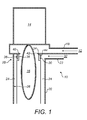
- apparatus 10 for treating a gas stream 12.
- the apparatus comprises a plasma generator 14 for generating a plasma flare 16.
- a first inlet 18 conveys the gas stream 12 into the apparatus.
- a reaction chamber 20 is located downstream of the plasma generator in which the gas stream is treated by the generated plasma flare. Some gas may be treated outside of the reaction chamber.
- a second inlet 22 receives a liquid 32, typically water, into the apparatus for establishing a liquid weir 24 over an interior surface 26 of the reaction chamber 22 for resisting the accumulation of solid deposits from plasma treatment on the interior surface 26.
- the reaction chamber is generally cylindrical in this example.
- a flow director is shown generally at 28 and is shown in more detail in Figures 2 and 3 .
- the flow director may be integral with the reaction chamber or may consist of an insert adapted to be fitted in a treatment apparatus.
- the flow director has an outer annular surface 30 in flow communication with the second inlet 22 and located relative to the interior surface 26 of the reaction chamber for directing water over the interior surface for establishing water weir 24.
- the flow director also has an inner annular surface 34 in flow communication with the outer annular surface 30 as shown by the small arrow 36 in Figure 1 so that liquid is directed to flow and over the inner annular surface 34 to resist depositing on the inner annular surface.
- the liquid flowing over the inner annular surfaces establishes a small water weir 38 which initially flows over the inner annular surface and then drops under gravity to be incorporated in the larger water weir 24. Accordingly, a water weir is established on both the inner and the outer surfaces of the flow director. Flow communication between the inner and outer annular surfaces is shown in more detail in Figure 3 .
- the flow director 28 has a barrier surface 40 located between the inner and outer annular surfaces 34, 30 on the one hand and the plasma generator 14 on the other hand for resisting wetting of the plasma generator by the water weirs 24, 38 flowing over the inner and outer annular surfaces.
- the barrier surface in this example is a flange extending generally radially inwardly to provide a physical barrier between the water weirs 24, 38 and the plasma generator. The barrier surface prevents damage occurring to the plasma generator.
- the barrier surface defines an aperture 42 through which the plasma flare 16 can extend into the reaction chamber. The aperture should be sufficiently large that the plasma flare does not ordinarily contact it, otherwise it could become degraded by the hot plasma.
- the inner and outer annular surfaces are formed by a generally annular wall 44 depending from the barrier surface 40 in a downstream direction. As shown in Figure 1 , the annular wall extends generally orthogonally to the barrier surface approximately 10-20 mm depending on the overall dimensions of the apparatus. Figures 2 and 3 show the flow director 28 in more detail.
- the inner annular surface 34 is generally cylindrical whilst the outer annular surface 30 in this example has a curved face for directing the liquid from the liquid inlet 22 over the interior walls of the reaction chamber.
- the barrier surface is made up of first and second surfaces 46, 48 formed by two flanges extending perpendicularly from the upstream edge of the annular wall 44. Barrier surface 46 resists the passage of water upstream from the main weir 24 whereas barrier surface 48 resists the passage of water upstream from the smaller weir 38.
- the surfaces 46, 48 are not aligned as is the case in the arrangement shown in Figure 1 .
- Figure 3 shows the flow director 28 in use and is a sectional view looking upstream at the flow director.
- Water 32 is conveyed into the apparatus through inlet 22 at an angle which is generally tangential to the annular shape of the flow director.
- the outer annular surface 30 directs the water through its full circumference in order to establish a water weir 24 over the 360° extent of the reaction chamber.
- the outer annular surface 30 together with the interior surface of the reaction chamber 26 forms an annular channel along which the water is conveyed.
- the curved outer annular surface also directs the water gradually in a downward direction.
- a break 50 in the annular wall 44 allows flow communication 36 between the inner and outer annular surfaces 30, 34 of the flow director.
- the break may be any type of interruption in the circumference of the annular wall, for example a through bore or channel, however the break should be configured so that some but not all of the water circulating over the outer annular surface is directed over the inner annular surface. In this way, the outer annular surface is not starved of water required to establish the main water weir over the full circumferential extent of the reaction chamber. Conversely, sufficient water must be conveyed to the inner annular surface to establish a water weir over the full annular extent of the inner surface.
- a through bore which has a conductance of preferably less than half of the inlet 22 may be preferred.
- this channel is selected to optimise the flow of water around the central orifice. If the channel is too large then a high flow of water enters the central orifice and creates a spray which causes detrimental cooling of the plasma flare. If the channel is too small the water entering the central orifice is insufficient to completely wash the inside walls of the orifice and prevent solid adhesion/build up.
- the through bore is tangentially aligned to convey water onto the inner annular surface 34 in a generally tangential direction to establish the smaller water weir 38 over the full circumferential extent of the inner annular surface. It also preferred that the through bore is located in a position which is generally diametrically opposed from the inlet 22 or at least not immediately downstream of the inlet 22 so that water being conveyed into the apparatus at pressure is not forced straight from the inlet 22 to the through bore 50.
- the outer annular surface has a diameter which is less than the diameter of the reaction chamber and in close proximity thereto so that liquid directed around the outer annular surface is transferred generally tangentially onto the interior surface of the reaction chamber so that the liquid weir is established over substantially all of the interior surface.
- a water inlet pressure of 1 to 1.5 bar a 2 mm spacing between the outer annular surface and the interior wall of the reaction chamber has been found to produce good results.
- the flow director may be an insert located at the mouth of the reaction chamber.
- the flow director also known as a weir guide, may be manufactured from sintered silicon carbide. This material, as well as other ceramics, has a high thermal stability and is therefore suitable to be located proximate the plasma flare, where the temperature can reach 1500°C. Silicon carbide is also chemically resistant to attack from halogen-containing chemicals (especially, fluorine and HF) which are widely used in the semiconductor industry.
Landscapes
- Chemical & Material Sciences (AREA)
- Engineering & Computer Science (AREA)
- Physics & Mathematics (AREA)
- Plasma & Fusion (AREA)
- General Chemical & Material Sciences (AREA)
- Chemical Kinetics & Catalysis (AREA)
- Materials Engineering (AREA)
- Organic Chemistry (AREA)
- Metallurgy (AREA)
- Mechanical Engineering (AREA)
- Spectroscopy & Molecular Physics (AREA)
- Analytical Chemistry (AREA)
- Oil, Petroleum & Natural Gas (AREA)
- Physical Or Chemical Processes And Apparatus (AREA)
- Plasma Technology (AREA)
- Treating Waste Gases (AREA)
- Chemical Vapour Deposition (AREA)
- Drying Of Semiconductors (AREA)
Claims (9)
- Einrichtung (10) zum Behandeln eines Gasstroms (12), mit einem Plasmagenerator (14) zum Erzeugen einer Plasmaflamme (16), einem ersten Einlaß (18) zum Fördern des Gasstroms in die Einrichtung, und einer Reaktionskammer (20) stromab des Plasmagenerators, in welcher der Gasstrom durch die erzeugte Plasmaflamme behandelt wird, einem zweiten Einlaß (22) zur Aufnahme einer Flüssigkeit in der Einrichtung zum Herstellen eines Flüssigkeitswehrs (24) über einer Innenoberfläche (26) der Reaktionskammer zum Verhindern der Anhäufung fester Ablagerungen aus der Plasmabehandlung auf der Innenoberfläche, und gekennzeichnet durch einen Strömungsrichter (28) mit einer äußeren Ringfläche (30) in Strömungsverbindung mit dem zweiten Einlaß, der relativ zur Innenoberfläche so angeordnet ist, dass die Flüssigkeit über die Innenoberfläche geleitet wird, und mit einer inneren Ringfläche (34) in Strömungsverbindung mit der äußeren Ringfläche, so dass Flüssigkeit über die innere Ringfläche strömen kann, um Ablagerungen auf der inneren Ringfläche zu verhindern.
- Einrichtung nach Anspruch 1, wobei der zweite Einlaß (22) relativ zum Strömungsrichter so abgewinkelt ist, dass Flüssigkeit vom zweiten Einlaß etwa tangential über die äußere Ringfläche (30) gefördert wird.
- Einrichtung nach Anspruch 1 oder 2, wobei der Strömungsrichter (28) eine Sperrfläche (40) aufweist, die zwischen der inneren und der äußeren Ringfläche und dem Plasmagenerator angeordnet ist, um ein Benetzen des Plasmagenerators durch Flüssigkeit zu verhindern, die mittels der inneren und der äußeren Ringfläche geleitet wird.
- Einrichtung nach Anspruch 3, wobei die Sperrfläche (40) eine Öffnung (42) bildet, durch welche die Plasmaflamme sich in die Reaktionskammer erstrecken kann.
- Einrichtung nach Anspruch 3 oder 4, wobei die innere und die äußere Ringfläche durch eine etwa ringförmige Wand (44) gebildet sind, die von der Sperrfläche in stromabwärtiger Richtung herabhängt.
- Einrichtung nach Anspruch 4, wobei die innere Ringfläche und die äußere Ringfläche durch einen Durchbruch (50) in der Ringwand in Strömungsverbindung stehen, der so geformt ist, dass er Flüssigkeit von der äußeren Ringfläche in einer etwa tangentialen Richtung relativ zur inneren Ringfläche leitet.
- Einrichtung nach Anspruch 6, wobei der Durchbruch (50) durch eine tangential gerichtete Bohrung durch die Ringwand gebildet ist.
- Einrichtung nach Anspruch 6, wobei die äußere Ringfläche (30) einen Durchmesser hat, der kleiner als der Durchmesser der Reaktionskammer (20) ist und in enger Nähe damit steht, so dass um die äußere Ringfläche geleitete Flüssigkeit etwa tangential auf die Innenoberfläche der Reaktionskammer überführt wird, so dass das Flüssigkeitswehr über im wesentlichen der gesamten Innenoberfläche gebildet wird.
- Einrichtung nach einem der vorhergehenden Ansprüche, wobei der Strömungsrichter aus Siliziumcarbit hergestellt ist.
Applications Claiming Priority (2)
| Application Number | Priority Date | Filing Date | Title |
|---|---|---|---|
| GB1114172.8A GB2493750A (en) | 2011-08-17 | 2011-08-17 | Apparatus for treating a gas stream |
| PCT/GB2012/051630 WO2013024247A1 (en) | 2011-08-17 | 2012-07-11 | Apparatus for treating a gas stream |
Publications (2)
| Publication Number | Publication Date |
|---|---|
| EP2744587A1 EP2744587A1 (de) | 2014-06-25 |
| EP2744587B1 true EP2744587B1 (de) | 2015-06-24 |
Family
ID=44800457
Family Applications (1)
| Application Number | Title | Priority Date | Filing Date |
|---|---|---|---|
| EP12743526.1A Active EP2744587B1 (de) | 2011-08-17 | 2012-07-11 | Vorrichtung zur bearbeitung eines gasstroms |
Country Status (8)
| Country | Link |
|---|---|
| US (1) | US9512518B2 (de) |
| EP (1) | EP2744587B1 (de) |
| JP (1) | JP6120288B2 (de) |
| KR (1) | KR101993487B1 (de) |
| CN (1) | CN103747848B (de) |
| GB (1) | GB2493750A (de) |
| TW (1) | TWI563117B (de) |
| WO (1) | WO2013024247A1 (de) |
Families Citing this family (4)
| Publication number | Priority date | Publication date | Assignee | Title |
|---|---|---|---|---|
| CN105879599A (zh) * | 2014-12-24 | 2016-08-24 | 苏州超等环保科技有限公司 | 一种防爆式等离子有机废气处理装置 |
| GB2535528A (en) * | 2015-02-23 | 2016-08-24 | Edwards Ltd | Apparatus for treating gas |
| US10584873B1 (en) * | 2016-05-06 | 2020-03-10 | David Bacon | Flare gas assembly |
| US12203651B2 (en) | 2019-11-07 | 2025-01-21 | Bht Services Pte. Ltd. | Apparatus for treating gaseous pollutant with plasma |
Family Cites Families (14)
| Publication number | Priority date | Publication date | Assignee | Title |
|---|---|---|---|---|
| US3149222A (en) * | 1962-08-21 | 1964-09-15 | Giannini Scient Corp | Electrical plasma-jet apparatus and method incorporating multiple electrodes |
| DE3810820A1 (de) * | 1988-03-30 | 1989-10-12 | Hoechst Ceram Tec Ag | Verfahren zur herstellung von gleitkoerpern mit hohlkammern |
| IT1275660B1 (it) | 1994-11-15 | 1997-10-17 | Enel Spa | Assieme di un distributore di acqua di lavaggio e di una piastra di captazione |
| US5833888A (en) * | 1996-12-31 | 1998-11-10 | Atmi Ecosys Corporation | Weeping weir gas/liquid interface structure |
| KR100755241B1 (ko) * | 2000-05-29 | 2007-09-04 | 가부시키가이샤 아도테쿠 프라즈마 테쿠노로지 | 피처리물처리장치 및 그것을 사용한 플라즈마설비 |
| US6962679B2 (en) * | 2001-07-11 | 2005-11-08 | Battelle Memorial Institute | Processes and apparatuses for treating halogen-containing gases |
| JP4107959B2 (ja) | 2002-12-27 | 2008-06-25 | 株式会社アドテック プラズマ テクノロジー | 放電の始動方法、この始動方法を利用した被処理物の処理方法、及びこの始動方法を利用した被処理物の処理装置 |
| UA87605C2 (uk) * | 2005-06-14 | 2009-07-27 | Юрій Міхайловіч Горовой | Установка для синтезу діоксиду титану |
| DE102005033585A1 (de) * | 2005-07-19 | 2007-02-01 | Bosch Rexroth Aktiengesellschaft | Registerregelung |
| JP5102217B2 (ja) * | 2005-10-31 | 2012-12-19 | アプライド マテリアルズ インコーポレイテッド | プロセス削減反応器 |
| GB0523947D0 (en) * | 2005-11-24 | 2006-01-04 | Boc Group Plc | Microwave plasma system |
| JP5307556B2 (ja) | 2007-01-30 | 2013-10-02 | カンケンテクノ株式会社 | ガス処理装置 |
| WO2009066395A1 (ja) | 2007-11-22 | 2009-05-28 | Adtec Plasma Technology Co., Ltd. | プラズマ処理装置 |
| US8323386B2 (en) | 2009-10-16 | 2012-12-04 | Midwest Research Institute, Inc. | Apparatus and method for electrostatic particulate collector |
-
2011
- 2011-08-17 GB GB1114172.8A patent/GB2493750A/en not_active Withdrawn
-
2012
- 2012-07-11 WO PCT/GB2012/051630 patent/WO2013024247A1/en not_active Ceased
- 2012-07-11 US US14/239,017 patent/US9512518B2/en active Active
- 2012-07-11 EP EP12743526.1A patent/EP2744587B1/de active Active
- 2012-07-11 KR KR1020147006773A patent/KR101993487B1/ko active Active
- 2012-07-11 JP JP2014525482A patent/JP6120288B2/ja active Active
- 2012-07-11 CN CN201280040090.6A patent/CN103747848B/zh active Active
- 2012-07-18 TW TW101125893A patent/TWI563117B/zh active
Also Published As
| Publication number | Publication date |
|---|---|
| KR101993487B1 (ko) | 2019-06-26 |
| US9512518B2 (en) | 2016-12-06 |
| GB2493750A (en) | 2013-02-20 |
| TW201313947A (zh) | 2013-04-01 |
| CN103747848A (zh) | 2014-04-23 |
| CN103747848B (zh) | 2016-04-06 |
| TWI563117B (en) | 2016-12-21 |
| KR20140064867A (ko) | 2014-05-28 |
| US20150027373A1 (en) | 2015-01-29 |
| JP6120288B2 (ja) | 2017-04-26 |
| GB201114172D0 (en) | 2011-10-05 |
| JP2014529492A (ja) | 2014-11-13 |
| WO2013024247A1 (en) | 2013-02-21 |
| EP2744587A1 (de) | 2014-06-25 |
Similar Documents
| Publication | Publication Date | Title |
|---|---|---|
| US11185815B2 (en) | Plasma abatement of compounds containing heavy atoms | |
| CN101535525B (zh) | 一种防止聚合物在cvd反应腔室的排气管线中形成的方法及装置 | |
| CN101755322B (zh) | 等离子体反应器 | |
| US7377771B2 (en) | Apparatus for the thermal treatment of process exhaust gases containing pollutants | |
| CN1720348A (zh) | 用来改善制程室边缘清洁速率的挡板旁通装置 | |
| KR101659432B1 (ko) | 반응성 가스 제어 | |
| US9512518B2 (en) | Apparatus for treating a gas stream | |
| CN108431923A (zh) | 用于泵送管线中的沉积物清洁的方法和设备 | |
| US10005025B2 (en) | Corrosion resistant abatement system | |
| WO2013024249A2 (en) | Apparatus for treating a gas stream | |
| WO2014109152A1 (ja) | インレットノズル、及び除害装置 | |
| CN113015573A (zh) | 废气导入喷嘴、水处理装置以及废气处理装置 | |
| JP4350338B2 (ja) | 排気ガス処理装置 | |
| TWI796368B (zh) | 噴嘴及其方法 | |
| KR102949336B1 (ko) | 반응기, 상기 반응기를 포함하는 플라즈마 발생 장치, 및 상기 플라즈마 발생 장치를 포함하는 배기 가스 처리 장치 | |
| KR102835543B1 (ko) | 플라즈마 발생기를 포함하는 배기 가스 처리 장치 | |
| JP6263345B2 (ja) | 燃焼除害装置 | |
| TW201820452A (zh) | 氣相蝕刻反應裝置與氣相蝕刻方法 | |
| CN113913784A (zh) | 气体幕帘元件、传送气体的导管系统与传送气体的方法 | |
| JP4583880B2 (ja) | 排ガスの処理方法および処理装置 | |
| CN112189114A (zh) | 除害装置以及进气喷嘴 | |
| HK40047102A (en) | Exhaust gas introduction nozzle, water treatment device, and exhaust gas treatment device | |
| KR20040032347A (ko) | 반도체 제조 설비에서의 부산물 배출시스템 | |
| KR20010034592A (ko) | 유체 유동 유입구 |
Legal Events
| Date | Code | Title | Description |
|---|---|---|---|
| PUAI | Public reference made under article 153(3) epc to a published international application that has entered the european phase |
Free format text: ORIGINAL CODE: 0009012 |
|
| 17P | Request for examination filed |
Effective date: 20140204 |
|
| AK | Designated contracting states |
Kind code of ref document: A1 Designated state(s): AL AT BE BG CH CY CZ DE DK EE ES FI FR GB GR HR HU IE IS IT LI LT LU LV MC MK MT NL NO PL PT RO RS SE SI SK SM TR |
|
| DAX | Request for extension of the european patent (deleted) | ||
| GRAP | Despatch of communication of intention to grant a patent |
Free format text: ORIGINAL CODE: EPIDOSNIGR1 |
|
| INTG | Intention to grant announced |
Effective date: 20150217 |
|
| GRAS | Grant fee paid |
Free format text: ORIGINAL CODE: EPIDOSNIGR3 |
|
| GRAA | (expected) grant |
Free format text: ORIGINAL CODE: 0009210 |
|
| AK | Designated contracting states |
Kind code of ref document: B1 Designated state(s): AL AT BE BG CH CY CZ DE DK EE ES FI FR GB GR HR HU IE IS IT LI LT LU LV MC MK MT NL NO PL PT RO RS SE SI SK SM TR |
|
| REG | Reference to a national code |
Ref country code: GB Ref legal event code: FG4D |
|
| REG | Reference to a national code |
Ref country code: CH Ref legal event code: EP |
|
| REG | Reference to a national code |
Ref country code: AT Ref legal event code: REF Ref document number: 732660 Country of ref document: AT Kind code of ref document: T Effective date: 20150715 |
|
| REG | Reference to a national code |
Ref country code: FR Ref legal event code: PLFP Year of fee payment: 4 |
|
| REG | Reference to a national code |
Ref country code: IE Ref legal event code: FG4D |
|
| REG | Reference to a national code |
Ref country code: DE Ref legal event code: R096 Ref document number: 602012008260 Country of ref document: DE |
|
| PG25 | Lapsed in a contracting state [announced via postgrant information from national office to epo] |
Ref country code: LT Free format text: LAPSE BECAUSE OF FAILURE TO SUBMIT A TRANSLATION OF THE DESCRIPTION OR TO PAY THE FEE WITHIN THE PRESCRIBED TIME-LIMIT Effective date: 20150624 Ref country code: NO Free format text: LAPSE BECAUSE OF FAILURE TO SUBMIT A TRANSLATION OF THE DESCRIPTION OR TO PAY THE FEE WITHIN THE PRESCRIBED TIME-LIMIT Effective date: 20150924 Ref country code: HR Free format text: LAPSE BECAUSE OF FAILURE TO SUBMIT A TRANSLATION OF THE DESCRIPTION OR TO PAY THE FEE WITHIN THE PRESCRIBED TIME-LIMIT Effective date: 20150624 Ref country code: FI Free format text: LAPSE BECAUSE OF FAILURE TO SUBMIT A TRANSLATION OF THE DESCRIPTION OR TO PAY THE FEE WITHIN THE PRESCRIBED TIME-LIMIT Effective date: 20150624 |
|
| REG | Reference to a national code |
Ref country code: AT Ref legal event code: MK05 Ref document number: 732660 Country of ref document: AT Kind code of ref document: T Effective date: 20150624 |
|
| REG | Reference to a national code |
Ref country code: LT Ref legal event code: MG4D |
|
| PG25 | Lapsed in a contracting state [announced via postgrant information from national office to epo] |
Ref country code: RS Free format text: LAPSE BECAUSE OF FAILURE TO SUBMIT A TRANSLATION OF THE DESCRIPTION OR TO PAY THE FEE WITHIN THE PRESCRIBED TIME-LIMIT Effective date: 20150624 Ref country code: BG Free format text: LAPSE BECAUSE OF FAILURE TO SUBMIT A TRANSLATION OF THE DESCRIPTION OR TO PAY THE FEE WITHIN THE PRESCRIBED TIME-LIMIT Effective date: 20150924 Ref country code: GR Free format text: LAPSE BECAUSE OF FAILURE TO SUBMIT A TRANSLATION OF THE DESCRIPTION OR TO PAY THE FEE WITHIN THE PRESCRIBED TIME-LIMIT Effective date: 20150925 Ref country code: LV Free format text: LAPSE BECAUSE OF FAILURE TO SUBMIT A TRANSLATION OF THE DESCRIPTION OR TO PAY THE FEE WITHIN THE PRESCRIBED TIME-LIMIT Effective date: 20150624 |
|
| REG | Reference to a national code |
Ref country code: NL Ref legal event code: MP Effective date: 20150624 |
|
| PG25 | Lapsed in a contracting state [announced via postgrant information from national office to epo] |
Ref country code: EE Free format text: LAPSE BECAUSE OF FAILURE TO SUBMIT A TRANSLATION OF THE DESCRIPTION OR TO PAY THE FEE WITHIN THE PRESCRIBED TIME-LIMIT Effective date: 20150624 |
|
| PG25 | Lapsed in a contracting state [announced via postgrant information from national office to epo] |
Ref country code: CZ Free format text: LAPSE BECAUSE OF FAILURE TO SUBMIT A TRANSLATION OF THE DESCRIPTION OR TO PAY THE FEE WITHIN THE PRESCRIBED TIME-LIMIT Effective date: 20150624 Ref country code: PL Free format text: LAPSE BECAUSE OF FAILURE TO SUBMIT A TRANSLATION OF THE DESCRIPTION OR TO PAY THE FEE WITHIN THE PRESCRIBED TIME-LIMIT Effective date: 20150624 Ref country code: RO Free format text: LAPSE BECAUSE OF NON-PAYMENT OF DUE FEES Effective date: 20150624 Ref country code: ES Free format text: LAPSE BECAUSE OF FAILURE TO SUBMIT A TRANSLATION OF THE DESCRIPTION OR TO PAY THE FEE WITHIN THE PRESCRIBED TIME-LIMIT Effective date: 20150624 Ref country code: IS Free format text: LAPSE BECAUSE OF FAILURE TO SUBMIT A TRANSLATION OF THE DESCRIPTION OR TO PAY THE FEE WITHIN THE PRESCRIBED TIME-LIMIT Effective date: 20151024 Ref country code: PT Free format text: LAPSE BECAUSE OF FAILURE TO SUBMIT A TRANSLATION OF THE DESCRIPTION OR TO PAY THE FEE WITHIN THE PRESCRIBED TIME-LIMIT Effective date: 20151026 Ref country code: AT Free format text: LAPSE BECAUSE OF FAILURE TO SUBMIT A TRANSLATION OF THE DESCRIPTION OR TO PAY THE FEE WITHIN THE PRESCRIBED TIME-LIMIT Effective date: 20150624 Ref country code: SK Free format text: LAPSE BECAUSE OF FAILURE TO SUBMIT A TRANSLATION OF THE DESCRIPTION OR TO PAY THE FEE WITHIN THE PRESCRIBED TIME-LIMIT Effective date: 20150624 |
|
| REG | Reference to a national code |
Ref country code: CH Ref legal event code: PL |
|
| REG | Reference to a national code |
Ref country code: DE Ref legal event code: R097 Ref document number: 602012008260 Country of ref document: DE |
|
| PG25 | Lapsed in a contracting state [announced via postgrant information from national office to epo] |
Ref country code: MC Free format text: LAPSE BECAUSE OF FAILURE TO SUBMIT A TRANSLATION OF THE DESCRIPTION OR TO PAY THE FEE WITHIN THE PRESCRIBED TIME-LIMIT Effective date: 20150624 |
|
| REG | Reference to a national code |
Ref country code: IE Ref legal event code: MM4A |
|
| PG25 | Lapsed in a contracting state [announced via postgrant information from national office to epo] |
Ref country code: CH Free format text: LAPSE BECAUSE OF NON-PAYMENT OF DUE FEES Effective date: 20150731 Ref country code: DK Free format text: LAPSE BECAUSE OF FAILURE TO SUBMIT A TRANSLATION OF THE DESCRIPTION OR TO PAY THE FEE WITHIN THE PRESCRIBED TIME-LIMIT Effective date: 20150624 Ref country code: LI Free format text: LAPSE BECAUSE OF NON-PAYMENT OF DUE FEES Effective date: 20150731 |
|
| PLBE | No opposition filed within time limit |
Free format text: ORIGINAL CODE: 0009261 |
|
| STAA | Information on the status of an ep patent application or granted ep patent |
Free format text: STATUS: NO OPPOSITION FILED WITHIN TIME LIMIT |
|
| 26N | No opposition filed |
Effective date: 20160329 |
|
| REG | Reference to a national code |
Ref country code: FR Ref legal event code: PLFP Year of fee payment: 5 |
|
| PG25 | Lapsed in a contracting state [announced via postgrant information from national office to epo] |
Ref country code: IE Free format text: LAPSE BECAUSE OF NON-PAYMENT OF DUE FEES Effective date: 20150711 |
|
| PG25 | Lapsed in a contracting state [announced via postgrant information from national office to epo] |
Ref country code: SI Free format text: LAPSE BECAUSE OF FAILURE TO SUBMIT A TRANSLATION OF THE DESCRIPTION OR TO PAY THE FEE WITHIN THE PRESCRIBED TIME-LIMIT Effective date: 20150624 |
|
| PG25 | Lapsed in a contracting state [announced via postgrant information from national office to epo] |
Ref country code: BE Free format text: LAPSE BECAUSE OF FAILURE TO SUBMIT A TRANSLATION OF THE DESCRIPTION OR TO PAY THE FEE WITHIN THE PRESCRIBED TIME-LIMIT Effective date: 20150624 |
|
| PG25 | Lapsed in a contracting state [announced via postgrant information from national office to epo] |
Ref country code: MT Free format text: LAPSE BECAUSE OF FAILURE TO SUBMIT A TRANSLATION OF THE DESCRIPTION OR TO PAY THE FEE WITHIN THE PRESCRIBED TIME-LIMIT Effective date: 20150624 |
|
| PG25 | Lapsed in a contracting state [announced via postgrant information from national office to epo] |
Ref country code: HU Free format text: LAPSE BECAUSE OF FAILURE TO SUBMIT A TRANSLATION OF THE DESCRIPTION OR TO PAY THE FEE WITHIN THE PRESCRIBED TIME-LIMIT; INVALID AB INITIO Effective date: 20120711 Ref country code: SM Free format text: LAPSE BECAUSE OF FAILURE TO SUBMIT A TRANSLATION OF THE DESCRIPTION OR TO PAY THE FEE WITHIN THE PRESCRIBED TIME-LIMIT Effective date: 20150624 |
|
| PG25 | Lapsed in a contracting state [announced via postgrant information from national office to epo] |
Ref country code: CY Free format text: LAPSE BECAUSE OF FAILURE TO SUBMIT A TRANSLATION OF THE DESCRIPTION OR TO PAY THE FEE WITHIN THE PRESCRIBED TIME-LIMIT Effective date: 20150624 Ref country code: NL Free format text: LAPSE BECAUSE OF FAILURE TO SUBMIT A TRANSLATION OF THE DESCRIPTION OR TO PAY THE FEE WITHIN THE PRESCRIBED TIME-LIMIT Effective date: 20150624 Ref country code: SE Free format text: LAPSE BECAUSE OF FAILURE TO SUBMIT A TRANSLATION OF THE DESCRIPTION OR TO PAY THE FEE WITHIN THE PRESCRIBED TIME-LIMIT Effective date: 20150624 |
|
| REG | Reference to a national code |
Ref country code: FR Ref legal event code: PLFP Year of fee payment: 6 |
|
| PG25 | Lapsed in a contracting state [announced via postgrant information from national office to epo] |
Ref country code: LU Free format text: LAPSE BECAUSE OF NON-PAYMENT OF DUE FEES Effective date: 20150711 |
|
| REG | Reference to a national code |
Ref country code: DE Ref legal event code: R082 Ref document number: 602012008260 Country of ref document: DE Representative=s name: FLEUCHAUS & GALLO PARTNERSCHAFT MBB PATENTANWA, DE Ref country code: DE Ref legal event code: R082 Ref document number: 602012008260 Country of ref document: DE Representative=s name: FLEUCHAUS & GALLO PARTNERSCHAFT MBB, DE Ref country code: DE Ref legal event code: R081 Ref document number: 602012008260 Country of ref document: DE Owner name: EDWARDS LTD., BURGESS HILL, GB Free format text: FORMER OWNER: EDWARDS LTD., CRAWLEY, WEST SUSSEX, GB |
|
| PG25 | Lapsed in a contracting state [announced via postgrant information from national office to epo] |
Ref country code: MK Free format text: LAPSE BECAUSE OF FAILURE TO SUBMIT A TRANSLATION OF THE DESCRIPTION OR TO PAY THE FEE WITHIN THE PRESCRIBED TIME-LIMIT Effective date: 20150624 Ref country code: TR Free format text: LAPSE BECAUSE OF FAILURE TO SUBMIT A TRANSLATION OF THE DESCRIPTION OR TO PAY THE FEE WITHIN THE PRESCRIBED TIME-LIMIT Effective date: 20150624 |
|
| REG | Reference to a national code |
Ref country code: FR Ref legal event code: PLFP Year of fee payment: 7 |
|
| REG | Reference to a national code |
Ref country code: FR Ref legal event code: CA Effective date: 20180906 |
|
| PG25 | Lapsed in a contracting state [announced via postgrant information from national office to epo] |
Ref country code: AL Free format text: LAPSE BECAUSE OF FAILURE TO SUBMIT A TRANSLATION OF THE DESCRIPTION OR TO PAY THE FEE WITHIN THE PRESCRIBED TIME-LIMIT Effective date: 20150624 |
|
| REG | Reference to a national code |
Ref country code: DE Ref legal event code: R082 Ref document number: 602012008260 Country of ref document: DE Representative=s name: FLEUCHAUS & GALLO PARTNERSCHAFT MBB - PATENT- , DE Ref country code: DE Ref legal event code: R082 Ref document number: 602012008260 Country of ref document: DE Representative=s name: FLEUCHAUS & GALLO PARTNERSCHAFT MBB PATENTANWA, DE |
|
| P01 | Opt-out of the competence of the unified patent court (upc) registered |
Effective date: 20230502 |
|
| PGFP | Annual fee paid to national office [announced via postgrant information from national office to epo] |
Ref country code: DE Payment date: 20250729 Year of fee payment: 14 |
|
| PGFP | Annual fee paid to national office [announced via postgrant information from national office to epo] |
Ref country code: IT Payment date: 20250721 Year of fee payment: 14 |
|
| PGFP | Annual fee paid to national office [announced via postgrant information from national office to epo] |
Ref country code: GB Payment date: 20250728 Year of fee payment: 14 |
|
| PGFP | Annual fee paid to national office [announced via postgrant information from national office to epo] |
Ref country code: FR Payment date: 20250725 Year of fee payment: 14 |