EP2743975A1 - End-effector device and substrate transport robot provided with said end-effector device - Google Patents
End-effector device and substrate transport robot provided with said end-effector device Download PDFInfo
- Publication number
- EP2743975A1 EP2743975A1 EP12822878.0A EP12822878A EP2743975A1 EP 2743975 A1 EP2743975 A1 EP 2743975A1 EP 12822878 A EP12822878 A EP 12822878A EP 2743975 A1 EP2743975 A1 EP 2743975A1
- Authority
- EP
- European Patent Office
- Prior art keywords
- pitch changing
- end effector
- blade
- effector device
- end portion
- Prior art date
- Legal status (The legal status is an assumption and is not a legal conclusion. Google has not performed a legal analysis and makes no representation as to the accuracy of the status listed.)
- Withdrawn
Links
Images













Classifications
-
- H—ELECTRICITY
- H10—SEMICONDUCTOR DEVICES; ELECTRIC SOLID-STATE DEVICES NOT OTHERWISE PROVIDED FOR
- H10P—GENERIC PROCESSES OR APPARATUS FOR THE MANUFACTURE OR TREATMENT OF DEVICES COVERED BY CLASS H10
- H10P72/00—Handling or holding of wafers, substrates or devices during manufacture or treatment thereof
- H10P72/30—Handling or holding of wafers, substrates or devices during manufacture or treatment thereof for conveying, e.g. between different workstations
-
- B—PERFORMING OPERATIONS; TRANSPORTING
- B25—HAND TOOLS; PORTABLE POWER-DRIVEN TOOLS; MANIPULATORS
- B25J—MANIPULATORS; CHAMBERS PROVIDED WITH MANIPULATION DEVICES
- B25J15/00—Gripping heads and other end effectors
- B25J15/0019—End effectors other than grippers
-
- H—ELECTRICITY
- H10—SEMICONDUCTOR DEVICES; ELECTRIC SOLID-STATE DEVICES NOT OTHERWISE PROVIDED FOR
- H10P—GENERIC PROCESSES OR APPARATUS FOR THE MANUFACTURE OR TREATMENT OF DEVICES COVERED BY CLASS H10
- H10P72/00—Handling or holding of wafers, substrates or devices during manufacture or treatment thereof
- H10P72/30—Handling or holding of wafers, substrates or devices during manufacture or treatment thereof for conveying, e.g. between different workstations
- H10P72/33—Handling or holding of wafers, substrates or devices during manufacture or treatment thereof for conveying, e.g. between different workstations into and out of processing chamber
- H10P72/3302—Mechanical parts of transfer devices
-
- H—ELECTRICITY
- H10—SEMICONDUCTOR DEVICES; ELECTRIC SOLID-STATE DEVICES NOT OTHERWISE PROVIDED FOR
- H10P—GENERIC PROCESSES OR APPARATUS FOR THE MANUFACTURE OR TREATMENT OF DEVICES COVERED BY CLASS H10
- H10P72/00—Handling or holding of wafers, substrates or devices during manufacture or treatment thereof
- H10P72/30—Handling or holding of wafers, substrates or devices during manufacture or treatment thereof for conveying, e.g. between different workstations
- H10P72/34—Handling or holding of wafers, substrates or devices during manufacture or treatment thereof for conveying, e.g. between different workstations the wafers being stored in a carrier, involving loading and unloading
- H10P72/3402—Mechanical parts of transfer devices
-
- H—ELECTRICITY
- H10—SEMICONDUCTOR DEVICES; ELECTRIC SOLID-STATE DEVICES NOT OTHERWISE PROVIDED FOR
- H10P—GENERIC PROCESSES OR APPARATUS FOR THE MANUFACTURE OR TREATMENT OF DEVICES COVERED BY CLASS H10
- H10P72/00—Handling or holding of wafers, substrates or devices during manufacture or treatment thereof
- H10P72/30—Handling or holding of wafers, substrates or devices during manufacture or treatment thereof for conveying, e.g. between different workstations
- H10P72/34—Handling or holding of wafers, substrates or devices during manufacture or treatment thereof for conveying, e.g. between different workstations the wafers being stored in a carrier, involving loading and unloading
- H10P72/3411—Handling or holding of wafers, substrates or devices during manufacture or treatment thereof for conveying, e.g. between different workstations the wafers being stored in a carrier, involving loading and unloading involving loading and unloading of wafers
- H10P72/3412—Batch transfer of wafers
-
- H—ELECTRICITY
- H10—SEMICONDUCTOR DEVICES; ELECTRIC SOLID-STATE DEVICES NOT OTHERWISE PROVIDED FOR
- H10P—GENERIC PROCESSES OR APPARATUS FOR THE MANUFACTURE OR TREATMENT OF DEVICES COVERED BY CLASS H10
- H10P72/00—Handling or holding of wafers, substrates or devices during manufacture or treatment thereof
- H10P72/70—Handling or holding of wafers, substrates or devices during manufacture or treatment thereof for supporting or gripping
- H10P72/76—Handling or holding of wafers, substrates or devices during manufacture or treatment thereof for supporting or gripping using mechanical means, e.g. clamps or pinches
- H10P72/7602—Handling or holding of wafers, substrates or devices during manufacture or treatment thereof for supporting or gripping using mechanical means, e.g. clamps or pinches the wafers being placed on a robot blade or gripped by a gripper for conveyance
Definitions
- the present invention relates to: an end effector device including a pitch changing mechanism and attached to a tip end portion of a robot arm, the pitch changing mechanism being capable of changing upper-lower intervals of plate-shaped members, more specifically, upper-lower intervals of a plurality of semiconductor wafers used in a semiconductor manufacturing process; a substrate conveying robot including the end effector device; a substrate processing device including the substrate conveying robot; and a substrate processing facility including the substrate processing device.
- a semiconductor manufacturing process includes a step of conveying a plurality of semiconductor wafers at once from a foup that houses the plurality of semiconductor wafers lined up in an upper-lower direction to a processing shelf in which the semiconductor wafers are subjected to predetermined processing. While the semiconductor wafers are being conveyed, the upper-lower interval (hereinafter referred to as a "pitch") between the adjacent semiconductor wafers may be changed. A pitch changing mechanism is used to change this pitch.
- a conventional pitch changing mechanism includes: a plurality of wafer holding trays each configured to receive the entire lower surface of the semiconductor wafer; and vertical shafts respectively provided at base end portions of the wafer holding trays (see PTL 1). Each of the wafer holding trays moves up and down along the vertical shaft and rotates around the vertical shaft in a horizontal plane.
- the wafer holding trays of the pitch changing mechanism hold the entire lower surfaces of the plurality of semiconductor wafers at a position opposed to the foup to take out the plurality of semiconductor wafers at once.
- the wafer holding trays move down, so that the pitch between the adjacent semiconductor wafers is shortened.
- the wafer holding trays rotate around the vertical shafts to house all the semiconductor wafers in the processing shelf.
- the applicants have thought of attaching the end effector device incorporating the pitch changing mechanism to the tip end portion of the robot arm to smoothly transfer the semiconductor wafers from the foup to a processing booth.
- the conventional pitch changing mechanism is large since the wafer holding tray receives the entire lower surface of the semiconductor wafer. Therefore, the conventional pitch changing mechanism is unsuitable for the incorporation into the end effector device.
- An object of the present invention is to provide an end effector device including a mechanism configured to change an interval between semiconductor wafers.
- the present invention is an end effector device attached to a tip end portion of a robot arm, the end effector device including: a blade including a base end portion and a tip end portion; and a support unit provided at the blade and configured to support peripheral portions of a plurality of plate-shaped members such that the plate-shaped members are parallel to one another and spaced apart from one another in an upper-lower direction and also configured to change intervals of the plate-shaped members.
- the wording "provided so as to be located at the blade” includes both a case where the support unit is directly provided at the blade and a case where the support unit is provided at a portion of the end effector device other than the blade in a manner similar to the above case.
- a peripheral portion of the plate-shaped member is supported by the support unit.
- the support unit since the support unit does not have to receive the entire surface of the plate-shaped member, a portion where the support unit supports the plate-shaped member can be reduced in size.
- the support unit configured to change the intervals of the plate-shaped members can be reduced in size so as to be suitable for the incorporation into the end effector device.
- the reduction in size also denotes that the size reduction that has been conventionally impossible is realized. That is, the reduction in size in the present application does not just means the size reduction.
- each of the plurality of pitch changing mechanisms includes holding portions, which are provided so as to be spaced apart from one another in a direction perpendicular to axes of the holding portions, each of the axes extending in one flat plane, and are configured to respectively hold peripheral portions of the plurality of plate-shaped members, each of the plurality of pitch changing mechanisms changes intervals of the plurality of plate-shaped members, the intervals being formed in a direction perpendicular to the one flat plane, at least one of the pitch changing mechanisms is provided at the support unit and is configured to move forward to the tip end portion of the blade and move backward to the base end portion of the blade, and the one of the pitch changing mechanisms holds the plate-shaped members at a position where the one of the pitch changing mechanisms has moved forward to the tip end portion of the blade and cancels the holding of the plate-shaped members at a position where the one of the pitch changing mechanisms has moved backward to the base end portion of the blade.
- the pitch changing mechanism when one pitch changing mechanism moves backward, the holding of the plate-shaped members by the holding portions of this pitch changing mechanism is cancelled. With this, the plurality of plate-shaped members whose intervals have been changed can be easily passed to the next processing stage.
- a configuration in which the pitch changing mechanism presses the peripheral portion of the plate-shaped member in a direction connecting the base end and tip end of the blade to hold the plate-shaped member is called an edge grip type.
- the incorporated support unit has a pitch changing function and supports the peripheral portions of the plate-shaped members. With this, a mechanism configured to change the pitches in the end effector device can be reduced in size.
- the present invention relates to an end effector device attached to a tip end portion of an arm of a substrate conveying robot.
- the conveying robot will be explained wholly.
- a horizontal plane is used as one example of "one flat plane" in the present invention.
- a circular plate-shaped semiconductor wafer is used as one example of a plate-shaped member conveyed by the conveying robot.
- the plate-shaped member is not limited to the semiconductor wafer.
- the plate-shaped member may be a glass substrate processed in a semiconductor process and used for a thin liquid crystal display or an organic EL display.
- the semiconductor wafer is a substrate material of a semiconductor device, and examples thereof include a silicon wafer, a silicon carbide wafer, and a sapphire wafer. Further, the semiconductor wafer does not have to be a material, and a circuit and/or a structure may be formed on the plate-shaped member.
- the shape of the semiconductor wafer is not limited to a circular shape.
- Examples of the processing of the semiconductor wafer include a heat treatment and film formation performed in a processing booth.
- a plurality of semiconductor wafers before the processing are housed in a foup (Front Opening Unified Pod), located away from the processing booth, such that each of the semiconductor wafers is in a horizontal posture, and the semiconductor wafers are lined up in an upper-lower direction.
- foup Front Opening Unified Pod
- a processing shelf for semiconductor wafer processing is provided in the processing booth.
- the processing shelf holds a plurality of semiconductor wafers such that each of the semiconductor wafers is in a horizontal posture, and the semiconductor wafers are lined up in the upper-lower direction.
- a plurality of semiconductor wafers are taken out from the foup at once to be conveyed to the processing shelf.
- the pitch between the adjacent semiconductor wafers in the processing shelf is different from the pitch between the adjacent semiconductor wafers in the foup in some cases.
- the pitch in the processing shelf is shorter than the pitch in the foup in some cases.
- used is a pitch changing mechanism configured to take out the plurality of semiconductor wafers from the foup and change the pitches while the plurality of semiconductor wafers are being conveyed to the processing shelf. This is the same as conventional cases.
- Components for housing the semiconductor wafers are not limited to the foup and the processing shelf. To be specific, any components may be used as long as the semiconductor wafers are housed in the components such that the pitches of the semiconductor wafers in one of the components are different from those of the semiconductor wafers in the other component.
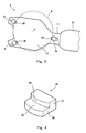
- Fig. 1 is a perspective view of an entire substrate conveying robot 2.
- the substrate conveying robot 2 is a robot configured to convey a plurality of semiconductor wafers lined up in the upper-lower direction.
- One example of the substrate conveying robot 2 is a so-called horizontally articulated three-axis robot.
- the substrate conveying robot 2 is configured such that: an arm supporting portion 23 capable of moving up and down is provided on a base 22 fixed to a semiconductor processing equipment; and one end portion of a first arm 20 extending in a horizontal direction is attached to an upper end portion of the arm supporting portion 23.
- the first arm 20 is provided so as to be rotatable relative to the arm supporting portion 23, and one end portion of a second arm 21 is pivotally supported by the other end portion of the first arm 20.
- a below-described end effector device 1 is attached to a terminal end portion of the second arm 21. Since the first arm 20 rotates relative to the arm supporting portion 23, and the second arm 21 rotates relative to the first arm 20 in the horizontal plane, the end effector device 1 moves in the horizontal plane. The end effector device can move in a height direction by the upward and downward movements of the arm supporting portion 23.
- the substrate conveying robot 2 may be included in a substrate processing device.
- the substrate processing device may be included in a substrate processing facility. The substrate processing device and the substrate processing facility will be described later.
- the end effector device 1 includes: a blade 10 having a base end portion attached to a tip end portion of the second arm 21; and a plurality of support units extending upward from the blade 10 (for example, in Fig. 1 , three support units 3, 3, and 3a).
- the support units 3 and 3a hold a plurality of semiconductor wafers 9 such that each of the semiconductor wafers 9 is in a horizontal posture, the semiconductor wafers 9 are spaced apart from one another in the upper-lower direction.
- the end effector device 1 configured such that the support units 3 are provided on the lower surface of the blade 10 or on both upper and lower surfaces of the blade 10 is also included in the technical scope of the present invention. However, for convenience of explanation, in the following example, the support units 3 extend upward from the blade 10.
- Fig. 2 is an enlarged perspective view of the end effector device 1
- Fig. 3 is a plan view of the end effector device 1.
- Two of the three support units 3, 3, and 3 a are tip end support units 3 located at a tip end portion of the blade 10, and the other is a base end support unit 3a located at the base end portion of the blade 10.
- An elongated hole 11 extending from the base end portion of the blade 10 toward the tip end side is formed on the base end portion of the blade 10.
- the base end support unit 3a is provided on the tip end portion of the second arm 21 to project upward from the blade 10 through the elongated hole 11.
- This configuration in which the base end support unit 3a is provided on the tip end portion of the second arm 21 to project upward from the blade 10 through the elongated hole 11 is also included in the configuration in which "the base end support unit 3a is provided so as to be located at the blade 10".
- the base end support unit 3 a moves on the tip end portion of the second arm 21 or on the blade 10 by a plunger (not shown) provided at the second arm 21. Specifically, the base end support unit 3a moves between a forward position where the base end support unit 3a has moved toward the tip end of the blade 10 and a backward position where the base end support unit 3a has moved toward the base end portion of the blade 10 from the forward position.
- the above embodiment has explained a case where the tip end support units 3 are fixed to the blade 10, and the base end support unit 3a moves along the elongated hole 11.
- one or both of the tip end support units 3 may be moved in a direction toward the center of the semiconductor wafer 9 or toward the base end portion of the blade 10. That is, the distance between the support units 3 may be shortened.
- Each of the support units 3 and 3a includes: a plurality of nail pieces 30 arranged so as to be spaced apart from one another in the upper-lower direction and each configured to support a peripheral portion of the semiconductor wafer 9; and a pitch changing mechanism 4 configured to change upper-lower intervals of the plurality of nail pieces 30.
- Three nail pieces 30, located at the same height, of the support units 3 and 3a support the peripheral portion of one semiconductor wafer 9.
- the three nail pieces 30, located at the same height, of the support units 3 and 3a are arranged radially relative to a center C of the semiconductor wafer 9. Since the horizontal plane at which the semiconductor wafer 9 should be located is determined by the three nail pieces 30, the semiconductor wafer 9 is substantially horizontally, stably supported by the three nail pieces 30.
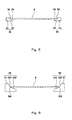
- Fig. 4 is a perspective view of the nail piece 30.
- the nail piece 30 is configured to have two stages such that a receiving piece 32 projects laterally from a lower end portion of a main body 31.
- An upper surface of the receiving piece 32 forms a receiving surface 33 that receives a lower surface of the peripheral portion of the semiconductor wafer 9.
- An inner side surface of the main body 31 forms a contact surface 34 that is substantially perpendicular to the receiving surface 33 and contacts a peripheral end surface of the semiconductor wafer 9.
- the nail piece 30 is made of synthetic resin. However, the present embodiment is not limited to this. It is preferable that the nail piece 30 be made of a material that does not damage the semiconductor wafer 9.
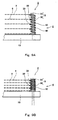
- Fig. 5 is a side view showing a state where the semiconductor wafer 9 is held by the nail pieces 30.
- the nail piece 30 is the edge grip type that stably holds the semiconductor wafer 9 by causing the contact surfaces 34 to inwardly push the peripheral edge of the semiconductor wafer 9.
- the nail pieces 30 located at the same height hold the semiconductor wafer 9. With this, the position of the semiconductor wafer 9 in the horizontal plane is stabilized. Further, even if the entire end effector device 1 is conveyed at high speed, the semiconductor wafer 9 is not displaced. As above, the edge grip type nail piece 30 is advantageous in that the semiconductor wafer 9 is stably held and conveyed. However, the nail piece 30 may have another configuration shown in Fig. 6 .
- Fig. 6 is a side view showing another type of nail pieces 30.
- the nail piece 30 includes: a first oblique surface 320 that is inclined inward and downward from an upper end portion of the main body 31; and a second oblique surface 330 that is formed at a lower side of the first oblique surface 320, is continuous with the first oblique surface 32, is inclined inward and downward, and has an inclination angle smaller than that of the first oblique surface 32.
- the peripheral portion of the semiconductor wafer 9 is placed at and held by a boundary SM between the first oblique surface 320 and the second oblique surface 330 at an inner side of each nail piece 30.
- the semiconductor wafer 9 slides on the first oblique surface 320 of the nail piece 30 to be placed at the boundary SM between the first oblique surface 320 and the second oblique surface 330 of the nail piece 30.
- the horizontal position and horizontal posture of the semiconductor wafer 9 relative to the pitch changing mechanism 4 are corrected, so that the semiconductor wafer 9 is stably held. Since the nail piece 30 and the semiconductor wafer 9 line-contact each other, an area of contact between the nail piece 30 and the semiconductor wafer 9 is small. With this, the adhesion of foreign matters to the semiconductor wafer 9 decreases.
- the end effector device 1 is located at a position opposed to the foup that houses a plurality of semiconductor wafers 9 such that the semiconductor wafers 9 are spaced apart from one another in the upper-lower direction.
- a plurality of semiconductor wafers are transferred from the foup to the end effector device 1 by the substrate conveying robot 2 while maintaining a state where the semiconductor wafers are spaced apart from one another in the upper-lower direction.
- the base end support unit 3a moves from the backward position to the forward position by the plunger to hold the semiconductor wafers 9.
- each nail piece 30 of the base end support unit 3a receives the lower surface of the peripheral portion of the semiconductor wafer 9, and the contact surface 34 of each nail piece 30 of the base end support unit 3a pushes the peripheral end surface of the semiconductor wafer 9 in a forward direction.
- the peripheral end surface of the semiconductor wafer 9 is pushed by the contact surfaces 34 of the nail pieces 30, located at the same height, of the tip end support units 3.
- the peripheral portion lower surface and peripheral end surface of the semiconductor wafer 9 are held by the three nail pieces 30 in the end effector device 1.
- only a part of the lower surface of the peripheral portion of the semiconductor wafer 9 is received by the nail pieces 30, and the nail pieces 30 do not cover the entire lower surface of the semiconductor wafer 9.
- the first arm 20 and the second arm 21 rotate, and the arm supporting portion 23 moves up and down.
- the plurality of semiconductor wafers 9 held by the end effector device 1 are conveyed to be in front of the processing shelf (not shown) in the processing booth for semiconductors.
- Supporting portions (not shown) each configured to receive the lower surface of the semiconductor wafer 9 are provided in the processing shelf.
- the supporting portions are moved so as to be respectively opposed to the lower surfaces of the semiconductor wafers 9, and then respectively contact lower surface exposed portions of the semiconductor wafers 9.
- the base end support unit 3a has moved to the backward position, the receiving surfaces 33 of the nail pieces 30 of the base end support unit 3a are separated from the lower surfaces of the peripheral portions of the semiconductor wafers 9.
- the semiconductor wafers 9 are not supported by the nail pieces 30 any more.
- the plurality of semiconductor wafers 9 are supported by the supporting portions to be conveyed to the processing shelf in the processing booth. Then, the semiconductor wafers 9 are subjected to the heat treatment and/or the film formation.
- the arm supporting portion 23 moves up and down, and the first arm 20 and the second arm 21 rotate. Thus, the end effector device 1 returns to the position opposed to the foup.
- the support unit 3 includes the pitch changing mechanism 4 configured to change the upper-lower intervals of the plurality of nail pieces 30.
- the following will explain various types of pitch changing mechanisms 4. For convenience of explanation, the pitch changing mechanism 4 of the tip end support unit 3 standing on the blade 10 will be explained. The same pitch changing mechanism 4 is provided at the base end support unit 3 a.
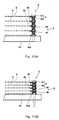
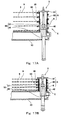
- Figs. 7A and 7B are partial cutaway views each showing a side surface of the pitch changing mechanism 4 according to Embodiment 1.
- Fig. 7A shows an initial state where the pitches are large
- Fig. 7B shows a state where the pitches are small.
- a piston pin 50 having a circular cross section is provided on the blade 10 so as to be able to move up and down, and a flange 51 is attached to an upper end portion of the piston pin 50.
- a spiral coil spring 40 extending in the upper-lower direction is fitted on the piston pin 50 and is configured such that spring pitches thereof are equal to one another.
- the coil spring 40 is a single compression coil spring, and the plurality of nail pieces 30 are arranged at an outer peripheral portion of the coil spring 40 so as to be spaced apart from one another in the upper-lower direction such that a tip end portion of each nail piece 30 faces a center portion of the semiconductor wafer 9.
- five nail pieces 30 are provided, and the nail piece 30 located at a lowest position contacts the blade 10 and does not move up or down. The other four nail pieces 30 move up and down.
- the number of nail pieces 30 is not limited to five.
- the intervals each between the adjacent nail pieces 30 are equally shortened from 10 mm to 6 mm.
- the intervals are shortened by pushing down the nail pieces 30 located at higher positions.
- the nail piece 30 located above and adjacent to the nail piece 30 located at the lowest position is pushed down by 4 mm, but the nail piece 30 located at the highest position is pushed down by 16 mm.
- a lowering distance of the nail piece 30 located at a higher position becomes larger.
- the intervals each between the nail pieces 30 may be shortened by pushing down the nail pieces 30 located at lower positions. Both pushing up and pushing down of the nail pieces 30 may be performed.
- the piston pin 50 serves as a part of an operating mechanism 5 configured to cause the coil spring 40 to elastically deform in the upper-lower direction to change the intervals each between the adjacent nail pieces 30.
- an operating mechanism 5 configured to cause the piston pin 50 to move up and down is a mechanism configured such that the piston pin 50 is connected to a solenoid or an air cylinder.
- the coil spring 40 In the initial state shown in Fig. 7A , the coil spring 40 is in a free length state or is being slightly pushed downward by the flange 51.
- the upper-lower interval between the adjacent nail pieces 30 is equal to one spring pitch, and the nail pieces 30 and the coil spring 40 are integrally made of synthetic resin.
- the nail piece 30 located at the highest position is in contact with a lower surface of the flange 51.
- the flange 51 presses the coil spring 40 downward, and the coil spring 40 contracts against an elastic biasing force until the adjacent coils tightly contact each other. Since distances each between the adjacent pitches are shortened, the intervals each between the adjacent nail pieces 30 are also shortened. As described above, since the nail pieces 30 receive the lower surfaces of the peripheral portions of the semiconductor wafers 9, the intervals each between the semiconductor wafers 9 adjacent to each other in the upper-lower direction are also shortened. With this, the upper-lower intervals of the plurality of semiconductor wafers taken out from the foup are shortened, and the plurality of semiconductor wafers are transferred to the processing booth.
- the end effector device 1 including the pitch changing mechanism 4 returns to the position opposed to the foup.
- the piston pin 50 moves up from the state shown in Fig. 7B to the state shown in Fig. 7A .
- the coil spring 40 expands upward by an elastic returning force.
- the upper-lower intervals each between the adjacent nail pieces 30 increase, and the pitch changing mechanism 4 returns to the initial state.
- the present embodiment may be configured such that the coil spring 40 is attached to the flange 51 and is pulled up by the piston pin 50.
- the piston pin 50 has the circular cross section, there is a possibility that the coil spring 40 and the nail pieces 30 unexpectedly rotate around the piston pin 50. In this case, there is a possibility that the nail pieces 3 rotate so as to be away from the lower surface of the semiconductor wafer 9 and therefore cannot receive the semiconductor wafer 9.
- a component for rotation stop is provided on the blade 10 as shown in Fig. 8 .
- Fig. 8 is a plan view of the nail piece 30 located at the lowest position when viewed from a direction A1 shown in Fig. 7A .
- a rotation stop piece 12 is provided on the blade 10 so as to surround the nail piece 30 located at the lowest position, and the nail piece 30 located at the lowers position is fitted in a concave 13 of the rotation stop piece 12.
- a side portion of the nail piece 30 contacts an inner side wall of the concave 13, so that the nail piece 30 located at the lowest position is prevented from unexpectedly rotating around the piston pin 50. Since the nail pieces 30 and the coil spring 40 are formed integrally, the rotation of the coil spring 40 around the piston pin 50 is also prevented.
- the nail pieces 30 support only a part of the lower surface of the peripheral portion of the semiconductor wafer 9 and does not cover the entire lower surface of the semiconductor wafer 9. Therefore, the pitch changing mechanism 4 can be made smaller and lighter than a conventional pitch changing mechanism 4 configured to support the entire lower surface of the semiconductor wafer 9. Therefore, the pitch changing mechanism 4 is suitably incorporated in the end effector device 1 attached to the tip end portion of the robot arm.
- Figs. 9A and 9B are partial cutaway views each showing the side surface of the pitch changing mechanism 4 according to Embodiment 2.
- Fig. 9A shows an initial state where the pitches are large
- Fig. 9B shows a state where the pitches are small.
- the pitch changing mechanism 4 of the present embodiment is configured such that: the spring pitch thereof is made shorter than, to be specific, is set to half the spring pitch of the coil spring 40 of the pitch changing mechanism 4 shown in Fig. 7A ; and one nail piece 30 is arranged for each spring pitch.
- the spring pitch contracts, and the adjacent coils tightly contact each other.
- the intervals each between the adjacent nail pieces 30 are shortened, so that as shown in Fig. 9B , the intervals each between the semiconductor wafers 9 adjacent to each other in the upper-lower direction are also shortened.
- the upper-lower intervals of the plurality of semiconductor wafers taken out from the foup are shortened, and the plurality of semiconductor wafers are transferred to the processing booth.
- Subsequent operations of the pitch changing mechanism 4 are the same as those of Embodiment 1, so that explanations thereof are omitted.
- Figs. 10A and 10B are partial cutaway views each showing the side surface of the pitch changing mechanism 4 according to Embodiment 3.
- Fig. 10A shows an initial state where the pitches are large
- Fig. 10B shows a state where the pitches are small.
- the piston pin 50 is a square shaft having a rectangular cross section, and a plurality of coil springs 40 are fitted on the piston pin 50 so as to be stacked at plural stages.
- the coil springs 40 herein are compression coil springs as with Embodiments 1 and 2, and each of the coil springs 40 herein is shorter than the coil spring 40 of each of Embodiments 1 and 2.
- the nail piece 30 is attached to the upper end portion of each of the coil springs 40, and the tip end portion of each nail piece 30 faces the center portion of the semiconductor wafer 9.
- a certain nail piece 30 and the coil spring 40 contacting the upper surface of the certain nail piece 30 are joined to each other, that is, the coil springs 40 adjacent to each other in the upper-lower direction are joined to each other via the nail piece 30.
- the nail pieces 30 adjacent to each other in the upper-lower direction are arranged so as to be spaced apart from each other in the upper-lower direction.
- Each nail piece 30 is fitted on the piston pin 50 to be moved up and down. In the initial state where the intervals each between the adjacent nail pieces 30 are large as shown in Fig.
- each of the coil springs 40 is in the free length state or is being slightly pushed downward.
- Five nail pieces 3 are provided.
- the nail piece 30a located at the lowest position is a fixed nail piece fixed to the blade 10, and the other four nail pieces 30 are movable nail pieces that move up and down.
- the coil springs 40 are pressed downward by the flange 51 to contract against upward elastic biasing forces until the adjacent coils tightly contact each other. Since the distances each between the adjacent pitches of the coil spring 40 are shortened, the intervals each between the adjacent nail pieces 30 are also shortened. Thus, as shown in Fig. 10B , the intervals each between the semiconductor wafers 9 adjacent to each other in the upper-lower direction are also shortened. With this, the upper-lower intervals of the plurality of semiconductor wafers taken out from the foup are shortened, and the plurality of semiconductor wafers are transferred to the processing booth.
- the nail piece 30 and the coil spring 40 may be formed integrally but do not have to be formed integrally. Therefore, the nail piece 30 and the coil spring 40 may be made of different materials.
- the nail piece 30 may be made of synthetic resin, and the coil spring 40 may be formed by a metal wire.
- the coil spring 40 a general-purpose product formed by the metal wire is commercially available. Therefore, the pitch changing mechanism 4 can be manufactured at low cost by using the coil spring 40 that is the general-purpose product and is made of metal.
- Fig. 11 is a perspective view of the nail piece 30 used in the pitch changing mechanism 4 of Embodiment 3.
- a through hole 35 having a rectangular shape is formed on the main body 31 of the nail piece 30 so as to penetrate the main body 31 in the upper lower direction.
- the piston pin 50 is fitted in the through hole 35 such that the nail piece 30 is slidable. With this, the nail piece 30 is prevented from unexpectedly rotating around the piston pin 50, and the nail piece 30 surely supports the lower surface of the semiconductor wafer 9.
- the piston pin 50 may be formed as a square shaft, and an inner opening of the coil spring 40 that is fitted on the piston pin 50 may be formed in a rectangular shape. That is, the piston pin 50 and the coil spring 40 may be formed in any shape as long as relative rotations thereof are prevented.
- Figs. 12A and 12B are partial cutaway views each showing the side surface of the pitch changing mechanism 4 according to Embodiment 4.
- Fig. 12A shows an initial state where the pitches are large
- Fig. 12B shows a state where the pitches are small.
- Fig. 13 is a side view of a cylindrical body 8 used in the pitch changing mechanism 4.
- the nail piece 30a located at the lowest position is a fixed nail piece fixed to the blade 10, and the other four nail pieces 30 are movable nail pieces.
- the pitch changing mechanism 4 includes the cylindrical body 8 provided on the blade 10, and a nail piece guide shaft 81 is provided inside the cylindrical body 8 so as to extend in the upper-lower direction.
- the cylindrical body 8 is provided so as to be rotatable around the nail piece guide shaft 81 in the horizontal plane.
- a plurality of spiral grooves 80 are formed on a peripheral surface of the cylindrical body 8 so as to penetrate the outer and inner sides of the cylindrical body 8 and respectively correspond to the nail pieces 30.
- An upper-lower length of a portion of the spiral groove 80 is called a spiral pitch, the portion corresponding to one circumference of the outer peripheral surface of the cylindrical body 8.
- the spiral pitch of the spiral groove 80 located at a higher position is larger, and the spiral pitch of the spiral groove 80 located at a lower position is smaller. This is because, as described above, to equally shorten the intervals each between the adjacent nail pieces 30, the lowering distance of the nail piece 30 located at a higher position needs to be larger.
- each nail piece 30 is fitted on the nail piece guide shaft 81, and the tip end portion thereof penetrates the spiral groove 80 to face the center portion of the semiconductor wafer 9.
- the nail piece guide shaft 81 is a square shaft, and as shown in Fig. 11 , the through hole 35 having a rectangular shape is formed on the main body 31 of the nail piece 30 of the present embodiment. Therefore, even if the cylindrical body 8 rotates, the nail pieces 30 do not rotate and are just allowed to move up and down.
- a timing belt 82 is wound around the lower end portion of the cylindrical body 8; and the other end portion of the timing belt 82 is connected to a direct drive device (not shown), such as a motor or air cylinder provided at the second arm 21.
- a direct drive device such as a motor or air cylinder provided at the second arm 21.
- a motor or air cylinder may be provided at the blade 10.
- the cylindrical body 8 is rotated in a clockwise direction when viewed from above.
- the nail pieces 30 move down along the spiral grooves 80.
- the spiral pitch of the spiral groove 80 located at a higher position is larger, and the spiral pitch of the spiral groove 80 located at a lower position is smaller. Therefore, the lowering distance of the nail piece 30 located at the highest position is the largest, and the lowering distance of the nail piece 30 located at a lower position becomes smaller.
- the downward movement of the nail piece 30 located at the highest position has been completed, as shown in Fig.
- the end effector device 1 including the pitch changing mechanism 4 returns to the initial state so as to be opposed to the foup.
- the cylindrical body 8 is rotated in a counterclockwise direction when viewed from above, and the nail pieces 30 are moved up from the state shown in Fig. 12B to the state shown in Fig. 12A .
- the pitch changing mechanism 4 returns to the initial state.
- the present embodiment may be configured such that: the nail piece guide shaft is provided outside the cylindrical body 8; and the nail pieces 30 are fitted in the spiral grooves 80 of the cylindrical body 8 (see Fig. 13 ; the nail piece guide shaft is not shown in Fig. 13 ).
- the spiral groove 80 does not have to penetrate the outside and inside of the cylindrical body 8 and may be formed on the peripheral surface of the cylindrical body 8.
- Figs. 14A and 14B are partial cutaway views each showing the side surface of the pitch changing mechanism 4 according to Embodiment 5 and showing another example of the operating mechanism 5 configured to cause the nail pieces 30 to move up and down.
- Fig. 14A shows an initial state where the pitches are large
- Fig. 14B shows a state where the pitches are small.
- the operating mechanism 5 includes: a hollow fixed shaft 6 standing on the blade 10; and an extendable shaft 60, whose lower surface is open and which is fitted on the fixed shaft 6 from an upper side of the fixed shaft 6 so as to be able to move up and down.
- the coil spring 40 including the plurality of nail pieces 30 respectively corresponding to the pitches are fitted outside the fixed shaft 6 and the extendable shaft 60.
- a flange 61 is provided at an upper end portion of the extendable shaft 60, and the nail piece 30 located at the highest position is attached to the flange 61.
- the operating mechanism 5 includes a cylinder (not shown) located at the base end portion side of the second arm 21, and the cylinder and the flange 61 are connected to each other via a wire 62 extending through the fixed shaft 6 and the extendable shaft 60.
- the wire 62 extends downward from the lower surface of the flange 61. After that, in the blade 10, the wire 62 winds around a pulley 63 provided under the fixed shaft 6, and then extends horizontally to be connected to the cylinder.
- a rotational center axis of the pulley 63 is substantially perpendicular to the wire 62 extending between the pulley 63 and the cylinder.
- the end effector device 1 including the pitch changing mechanism 4 returns to the position opposed to the foup.
- the cylinder cancels the pulling operation of the wire 62.
- the coil spring 40 moves up by the elastic returning force.
- the intervals each between the adjacent nail pieces 30 increase, and the pitch changing mechanism 4 returns to the initial state.
- the cylinder that is a driving source of the operating mechanism 5 is provided outside the blade 10 and at the base end portion side of the second arm 21.
- the cylinder is not provided in or on the blade 10. Therefore, the pitch changing mechanism 4 can be reduced in size so as to be suitable for the incorporation into the end effector device 1.
- the weight of the cylinder since the weight of the cylinder is not applied to the tip end portion of the second arm 21, the weight on the tip end portion of the second arm 21 can be reduced, and the tip end portion of the second arm 21 can operate smoothly.
- Figs. 15A and 15B are partial cutaway views each showing the side surface of the pitch changing mechanism 4 according to Embodiment 6.
- Fig. 15A shows an initial state where the pitches are large
- Fig. 15B shows a state where the pitches are small.
- the operating mechanism 5 includes the fixed shaft 6 and the extendable shaft 60, the coil spring 40 including a plurality of nail pieces 30 respectively corresponding to the pitches is fitted outside the fixed shaft 6 and the extendable shaft 60, and the flange 61 of the extendable shaft 60 is pulled downward by the wire 62.
- a tip end portion of a rotary shaft 64 extending from a motor or rotary actuator (not shown) provided at the second arm 21 is connected to the pulley 63 provided in the blade 10 so as to be located under the fixed shaft 6, and the pulley 63 is directly rotated by the rotary shaft 64.
- the rotational center axis of the pulley 63 is substantially parallel to a longitudinal direction of the rotary shaft 64.
- Figs. 16A and 16B are partial cutaway views each showing the side surface of the pitch changing mechanism 4 according to Embodiment 7.
- Fig. 16A shows an initial state where the pitches are large
- Fig. 16B shows a state where the pitches are small.
- the operating mechanism 5 includes the fixed shaft 6 and the extendable shaft 60
- the coil spring 40 including the plurality of nail pieces 30 respectively corresponding to the pitches is fitted outside the shafts 6 and 60
- the flange 61 of the extendable shaft 60 is pulled downward.
- the flange 61 is moved up and down not by the wire 62 but by an air cylinder 55 provided in the extendable shaft 60.
- the air cylinder 55 is a double acting type configured such that: a piston rod 57 is provided at a cylinder main body 56 having a cylindrical shape so as to be projectable; and the piston rod 57 reciprocates by introducing air to the cylinder main body 56 or by suctioning air from the cylinder main body 56. A tip end portion of the piston rod 57 is connected to the flange 61, so that the piston rod 57 causes the flange 61 to move up and down.
- Figs. 17A and 17B are partial cutaway views each showing the side surface of the pitch changing mechanism 4 according to Embodiment 8.
- Fig. 17A shows an initial state where the pitches are large
- Fig. 17B shows a state where the pitches are small.
- the operating mechanism 5 includes the fixed shaft 6 and the extendable shaft 60, the coil spring 40 including the plurality of nail pieces 30 respectively corresponding to the pitches are fitted outside the shafts 6 and 60, and the flange 61 of the extendable shaft 60 is pulled downward by the air cylinder 55.
- the air cylinder 55 is a single acting type configured such that the piston rod 57 is moved in only one direction by performing only one of air suction and air introduction.
- the single acting type air cylinder 55 is simpler in configuration and lower in price than the double acting type air cylinder 55. Therefore, the pitch changing mechanism 4 that can be incorporated in the end effector device 1 can be configured to have a simple configuration and be low in price.
- Fig. 18 is a plan view of the pitch changing mechanism 4 according to Embodiment 9.
- Fig. 19 is a perspective view showing major portions of the pitch changing mechanism 4.
- Figs. 20A and 20B are side views each showing the pitch changing mechanism 4 when viewed from a direction B1 of Fig. 18 .
- Fig. 20A shows an initial state where the pitches are large, and
- Fig. 20B shows a state where the pitches are small.
- the pitch changing mechanism 4 causes four nail pieces 30, located at different heights, to move up and down such that the nail pieces 30 support the peripheral portions of the corresponding semiconductor wafers 9.
- a movement stroke of the nail piece 30 located at a higher position is larger.
- the pitch changing mechanism 4 includes a long and thin swinging plate 7 provided inside the blade 10 and also inside an attachment position of the semiconductor wafer 9 and configured to swing around a central shaft 70 in a vertical plane, and the swinging plate 7 causes the nail pieces 30 to move up and down.
- the swinging plate 7 causes the nail pieces 30 to move up and down.
- a small motor is coupled to the central shaft 70.
- a plurality of elongated holes 71, the number of which corresponds to the number of nail pieces 30, are formed on the swinging plate 7 so as to extend along a longitudinal direction of the swinging plate 7.
- the nail pieces 30 are respectively attached to support shafts 72 each having a substantially L shape, and each of the support shafts 72 integrally includes: a vertical shaft 73 extending in a vertical direction and having an upper end portion to which the nail piece 30 is attached; and a horizontal shaft 74 extending in a horizontal direction from a lower end portion of the vertical shaft 73. A tip end portion of the horizontal shaft 74 is fitted in the corresponding elongated hole 71.
- the horizontal shaft 74 of the support shaft 72 is fitted in the elongated hole 71 located closer to the central shaft 70 of the swinging plate 7. With this, up/down strokes of the nail piece 30 located at a higher position become larger.
- the vertical shafts 73 linearly move up and down, the vertical shafts 73 are respectively fitted in thrust bearings (not shown) provided on the blade 10.
- the swinging plate 7 is inclined such that a tip end portion thereof is located at an upper side as shown by a solid line and contacts an upper stopper 77 located in the blade 10.
- An inclination angle of the swinging plate 7 relative to the horizontal plane at this time is ⁇ .
- the nail pieces 30 lined up in the upper lower direction are located substantially at regular intervals.
- the swinging plate 7 When the swinging plate 7 is inclined such that the tip end portion thereof is located at a lower side, and the angle of the swinging plate 7 relative to the horizontal plane is ⁇ , that is, when the swinging plate 7 is rotated downward by an angle 2 ⁇ from the initial state, the swinging plate 7 contacts a lower stopper 78 located in the blade 10 to stop.
- the nail pieces 30 lined up in the upper-lower direction are located substantially at regular intervals, and the intervals are shorter than those in the initial state.
- the end effector device 1 including the pitch changing mechanism 4 returns to the position opposed to the foup.
- the swinging plate 7 is rotated upward by the angle 20 around the central shaft 70.
- the nail pieces 30 return to the initial state.
- Figs. 21A and 21B are partial cutaway views each showing the side surface of the pitch changing mechanism 4 according to Embodiment 10.
- Fig. 21A shows an initial state where the pitches are large
- Fig. 21B shows a state where the pitches are small.
- Fig. 21C is a cross-sectional view taken along line C1-C1 of Fig. 21A , which is viewed from a back surface of the pitch changing mechanism.
- a plurality of nail pieces 30 are fitted on the piston pin 50 that is a square shaft having an upper end portion at which the flange 51 is provided.
- a mechanism of causing the piston pin 50 to move up and down is the same as that in Embodiment 3.
- the nail pieces 30 adjacent to each other in the upper-lower direction are connected to each other by a clip 45 that is an elastic member.
- the clip 45 is configured such that leg pieces 47 respectively project from upper and lower ends of a circular-arc supporting piece 46 so as to spread outward. When the clip 45 is pressed such that an angle between the leg pieces 47 is reduced, the clip 45 generates an elastic force in a direction opposite to a direction in which the clip 45 is pressed. As shown in Fig.
- the clips 45 are located at width direction end portions of the nail pieces 30, and the clips 45 adjacent to each other in the upper-lower direction are respectively provided at one end portion and the other end portion of the nail piece 30. With this, the elastic forces of the clips 45 are equally applied to both width direction end portions of each of the nail pieces 30.
- the flange 51 pushes the leg pieces 47 of the clips 45 such that the angles each between the leg pieces 47 decrease.
- the clips 45 contract against the elastic biasing forces. Since the distances each between the adjacent pitches are shortened, the intervals each between the adjacent nail pieces 30 are also shortened. As described above, since the nail pieces 30 receive the lower surfaces of the peripheral portions of the semiconductor wafers 9, the intervals each between the semiconductor wafers 9 adjacent to each other in the upper-lower direction are also shortened. With this, the upper-lower intervals of the plurality of wafers 9 taken out from the foup are shortened, and the plurality of wafers 9 are transferred to the processing booth.
- the end effector device 1 including the pitch changing mechanism 4 returns to the position opposed to the foup.
- the piston pin 50 is moved up from the state shown in Fig. 21B to the state shown in Fig. 21A .
- the clips 45 elastically return such that the angles each between the leg pieces 47 increase, and the pitch changing mechanism 4 returns to the initial state. To be specific, even if the piston pin 50 does not pull up the clips 45, the pitch changing mechanism 4 returns to the initial state.
- Figs. 22A and 22B are partial cutaway views each showing the side surface of the pitch changing mechanism 4 according to Embodiment 11.
- Fig. 22A shows an initial state where the pitches are large
- Fig. 22B shows a state where the pitches are small.
- the operating mechanism 5 includes the fixed shaft 6 and the extendable shaft 60 having the upper end portion at which the flange 61 is provided, and the coil spring 40 including the plurality of nail pieces 30 respectively corresponding to the pitches is fitted outside the fixed shaft 6 and the extendable shaft 60.
- a substantially triangle swinging member 67 configured to swing in the vertical surface around the central shaft 70 provided in the blade 10 is provided.
- One end portion of the swinging member 67 and the flange 61 of the extendable shaft 60 are connected to each other via a vertical wire 65.
- a cylinder or motor (not shown) provided at the second arm 21 and the other end portion of the swinging member 67 are connected to each other via a horizontal wire 62 or a rod.
- a point of connection between one end portion of the swinging member 67 and the vertical wire 65 is shown as S1
- a point of connection between the other end portion of the swinging member 67 and the horizontal wire 62 or rod is shown as S2.
- a distance L1 from the central shaft 70 to the connection point S1 is longer than a distance L2 from the central shaft 70 to the connection point S2.
- the swinging member 67 may have an L shape. To be specific, the positional relation among the central shaft 70, the connection point S1, and the connection point S2 may be maintained as in the above explanations.
- Figs. 23A and 23B are partial cutaway views each showing the side surface of the pitch changing mechanism 4 according to Embodiment 12.
- Fig. 23A shows an initial state where the pitches are large
- Fig. 23B shows a state where the pitches are small.
- the present embodiment is basically the same in configuration as Embodiment 11. However, a vertical distance L3 from the central shaft 70 to the connection point S2 is shorter than that in Embodiment 11. With this, even if the blade 10 is thin, the coil spring 40 at which the nail pieces 30 are provided can be caused to contract by using the swinging member 67.
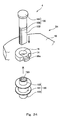
- Fig. 24 is an exploded perspective view of the pitch changing mechanism 4 according to Embodiment 13, and for convenience sake, the coil spring 40 is not shown.
- Figs. 25A and 25B are cross-sectional views each showing the pitch changing mechanism 4 when viewed from a direction D1 of Fig. 24 .
- Fig. 25A shows an initial state where the pitches are large
- Fig. 25B shows a state where the pitches are small.
- a plurality of nail pieces 30 are attached to the outer peripheral surface of the coil spring 40 at regular intervals in the upper-lower direction, and the nail piece 30a located at the lowest position is a fixed nail piece.
- the coil spring 40 is fitted on an up-and-down shaft 100 vertically provided at the blade 10.
- the up-and-down shaft 100 includes a flange body 101 located at an upper end portion thereof.
- a threaded shaft 102 is formed so as to extend downward from a longitudinal direction middle portion of the up-and-down shaft 100. The length of the threaded shaft 102 is determined in accordance with the up-down amount of the highest nail piece 30, that is, the longest up-down stroke.
- a vertically long cutout portion 103 is formed at a part of a peripheral surface of the threaded shaft 102, so that the threaded shaft 102 has a substantially D-shaped cross section.
- the nail piece 30a located at the lowest position is formed integrally with a receiving ring 14 fixed to the blade 10.
- a prevention hole 15 corresponding to the D-shaped cross section of the threaded shaft 102 is formed at the receiving ring 14.
- a bracket 110 having an upper surface on which a concave 111 is formed is attached to a position on the lower surface of the blade 10, the position corresponding to the up-and-down shaft 100.
- Bearings 112 are respectively attached to a lower surface of the concave 111 of the bracket 110 and the lower surface of the blade 10.
- a pulley assembly 120 (see Fig. 24 ) is provided between the lower surface of the blade 10 and the bracket 110.
- the pulley assembly 120 is configured such that receiving tubes 122 respectively project from upper and lower surfaces of a driven pulley 121.
- the driven pulley 121 is hollow, and a threaded surface 123 with which the threaded shaft 102 is threadedly engaged is formed on each of inner surfaces of the receiving tubes 122.
- the receiving tubes 122 are respectively, rotatably fitted in the bearings 112.
- a motor (not shown) for causing the driven pulley 121 to rotate is provided at the second arm 21 (see Fig. 1 ), and an endless belt 124 extends between the motor and the driven pulley 121.
- the driven pulley 121 rotates, so that the receiving tubes 122 rotate.
- the receiving tubes 122 apply a rotational force to the threaded shaft 102.
- the threaded shaft 102 is fitted in the prevention hole 15, so that the rotation thereof is prevented. Therefore, only the up-and-down movements of the threaded shaft 102 by the rotation of the driven pulley 121 are allowed.
- the end effector device 1 including the pitch changing mechanism 4 returns to the position opposed to the foup.
- the motor is reversely rotated, and the coil spring 40 configured to cause the threaded shaft 102 to move up expands upward by the elastic returning force.
- the upper-lower intervals each between the adjacent nail pieces 30 increase, and the pitch changing mechanism 4 returns to the initial state.
- the coil spring 40 is formed clockwise when viewed from above.
- the threaded shaft 102 on which the coil spring 40 is fitted is formed clockwise when viewed from above. Therefore, there is a possibility that when causing the coil spring 40 to expand or contract, the inside of the coil spring 40 is caught on the threaded shaft 102. On this account, it is preferable that the coil spring 40 be formed counterclockwise.
- the intervals each between the adjacent nail pieces 30 are shortened while the end effector device 1 in the initial state is conveyed to the processing booth.
- the intervals each between the adjacent nail pieces 30 may be increased while the end effector device 1 in the initial state is conveyed to the processing booth.
- the semiconductor wafer 9 is substantially horizontally supported by three nail pieces 30. However, the semiconductor wafer 9 does not have to be in a substantially horizontal state.
- the blade 10 does not have to have a plate shape shown in Fig. 1 .
- the blade 10 may have a structure, such as a frame structure in which frames are combined. That is, the blade 10 may have any structure as long as it can hold the support units and support a plurality of semiconductor wafers.
- the term "hold” means a state where the semiconductor wafer can be conveyed by the end effector device and includes states in addition to the edge grip. For example, only the lower surface of the semiconductor wafer 9 may be supported. In this case, the positional displacement between the semiconductor wafer 9 and the nail piece 30 is limited by the frictional force.
- the coil spring 40 of pitch changing mechanism 4 does not have to be contracted until the adjacent coils thereof tightly contact each other.
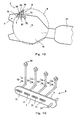
- Fig. 26 is an enlarged perspective view of the end effector device 1 according to Embodiment 2.
- the end effector device 1 includes: the blade 10 formed in a flat plate shape and having the base end portion attached to the tip end portion of the second arm 21; two pitch changing mechanisms 4 attached to the tip end portion of the blade 10 so as to be spaced apart from each other; and the support unit 3 provided on the second arm 21 so as to be opposed to the base end portion of the blade 10.
- each of the pitch changing mechanisms 4 changes the upper-lower pitches of the plurality of semiconductor wafers 9 arranged so as to be spaced apart from one another in the upper-lower direction.
- the pitch changing mechanism 4 herein is different in configuration from the pitch changing mechanisms 4 of the above embodiments.
- the support unit 3 is configured such that: the pitch changing mechanism 4 is provided on an outer surface of a box body 350; and two first guide pins 310 are respectively provided at both sides of the pitch changing mechanism 4 so as to be each opposed to peripheral edges of the semiconductor wafers 9 with a slight gap between the first guide pin 310 and each semiconductor wafer 9.
- a below-described driving source unit 600 is provided on the second arm 21 so as to be located at one side of the support unit 3.
- the box body 350 moves on the tip end portion of the second arm 21 by a plunger (not shown) provided at the second arm 21. Specifically, the box body 350 moves between a forward position where the box body 350 has moved toward the tip end of the blade 10 and a backward position where the box body 350 has moved toward the base end portion of the blade 10 from the forward position.
- the pitch changing mechanisms 4 located at the tip end portion of the blade 10 are provided on the upper surface of the blade 10.
- the pitch changing mechanisms 4 may be provided anywhere as long as they are provided at the blade 10.
- the pitch changing mechanisms 4 may be provided on the lower surface of the blade 10.
- the pitch changing mechanism 4 is provided to extend upward from the blade 10 in the following example.
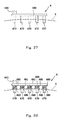
- Figs. 27A and 27B are plan views of the end effector device 1 and show the operation of the support unit 3.
- Fig. 27A shows the backward position
- Fig. 27B shows the forward position.
- Each of the pitch changing mechanisms 4 includes a plurality of nail pieces 30 arranged so as to be spaced apart from one another in the upper-lower direction and each configured to hold the peripheral portion of the semiconductor wafer 9.
- the shape of the nail piece 30 is the same as that in Fig. 4 , and the nail piece 30 constitutes a "holding portion" in the present invention.
- Three nail pieces 30, located at the same height, of the pitch changing mechanisms 4 hold the peripheral portion of one semiconductor wafer 9.
- the pitch changing mechanism 4 of the support unit 3 is not located at a position for holding the semiconductor wafer 9.
- a plurality of semiconductor wafers 9 taken out from the foup and arranged so as to be spaced apart from one another in the upper-lower direction are conveyed onto the blade 10.
- the support unit 3 moves toward the forward position.
- the nail pieces 30 of the pitch changing mechanism 4 of the support unit 3 hold the peripheral portions of the semiconductor wafers 9.
- Fig. 27B three nail pieces 30, located at the same height, of the pitch changing mechanisms 4 are arranged radially relative to a center C of the semiconductor wafer 9. Since the horizontal plane at which the semiconductor wafer 9 should be located is determined by the three nail pieces 30, the semiconductor wafer 9 is substantially horizontally, stably supported by the three nail pieces 30.
- two second guide pins 500 stand so as to be spaced apart from the first guide pins 310 and opposed to the peripheral edges of the semiconductor wafers 9. The reason for this will be described later.
- one of or both of the pitch changing mechanisms 4 may be moved in a direction toward the center of the semiconductor wafer 9 or the base end portion of the blade 10.
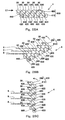
- Figs. 28A, 28B, and 28C are diagrams each showing the configuration and operation of the pitch changing mechanism 4 according to Embodiment 14, and the pitch changing mechanism 4 located at the tip end portion of the blade 10 of Fig. 26 is viewed from a direction B.
- the pitch changing mechanism 4 includes a rotating member 450 configured to rotate around a horizontal line in a vertical plane.
- the rotating member 450 includes: a first link member 400 having a long plate shape; a second link member 410 that constitutes a parallel link together with the first link member 400; and a plurality of connection link members 420 configured to couple the link members 400 and 410 to each other.
- the plurality of connection link members 420 are provided at regular intervals along the longitudinal direction of the link members 400 and 410.
- connection link members 420 are provided obliquely relative to the link members 400 and 410 and are attached so as to be rotatable relative to the link members 400 and 410 by rotating shafts 430 provided on the link members 400 and 410.
- the nail piece 30 is provided at an upper end portion of each connection link member 420 in such a posture as to be able to hold the peripheral portion of the semiconductor wafer 9.
- a driving shaft 440 is provided concentrically with the rotating shaft 430 provided at one end portion (left end portion in Fig. 28A ) of the second link member 410.
- the second link member 410 rotates in a vertical plane by the rotation of the driving shaft 440.
- the nail pieces 30 are located on substantially the same horizontal plane, and the positions of the nail pieces 30 and the link members 400 and 410 are referred to as "stand-by positions".
- connection link members 420 are attached to the link members 400 and 410 so as to be rotatable relative to the link members 400 and 410 by the rotating shafts 430, the connection link members 420 and the nail pieces 30 maintain postures before the rotation.
- the nail piece 30 located farther from the driving shaft 440 moves up more, and the upper-lower intervals each between the adjacent nail pieces 30 become larger than those in the case of the stand-by positions.
- the plurality of nail pieces 30 are provided such that the pitches thereof are equal to one another.
- the positions of the nail pieces 30 and the link members 400 and 410 at this time are referred to as "intermediate positions".
- the link members 400 and 410 When the second link member 410 is rotated in a counterclockwise direction from the intermediate position by the further rotation of the driving shaft 440 in the counterclockwise direction, the link members 400 and 410 become vertical states as shown in Fig. 28C .
- the nail pieces 30 maintain such postures as to be able to hold the peripheral portions of the semiconductor wafers 9.
- the pitches each between the adjacent nail pieces 30 become maximum.
- the positions of the nail pieces 30 and the link members 400 and 410 at this time are referred to as an "up positions".
- the pitch changing mechanism 4 changes the pitches of the plurality of nail pieces 30 configured to hold the semiconductor wafers 9.
- the support unit 3 When the end effector device 1 is not in use, the support unit 3 is located at the backward position.
- the nail pieces 30 of the pitch changing mechanism 4 and the link members 400 and 410 are located at the stand-by positions.
- the support unit 3 moves from the backward position to the forward position while maintaining the nail pieces 30 of the pitch changing mechanism 4 at the up positions. As described above, each semiconductor wafer 9 is held by three nail pieces 30 located at the same height.
- the driving shaft 440 of the pitch changing mechanism 4 rotates, and the link members 400 and 410 rotate in the clockwise direction.
- the pitches each between the adjacent semiconductor wafers 9 are shortened.
- the first arm 20 and the second arm 21 are rotated, so that the end effector device 1 is moved to the processing shelf. Then, the semiconductor wafer 9 is processed.
- the semiconductor wafers 9 are held by three pitch changing mechanisms 4, and the driving shafts 440 of the pitch changing mechanisms 4 rotate in synchronization with one another.
- a mechanism for causing the driving shafts 440 to rotate in synchronization with one another will be described later.
- three sets of the link members 400 and 410 rotate in synchronization with one another, and the three nail pieces 30 that hold the semiconductor wafer 9 at the same height move up and down in synchronization with one another. Therefore, the semiconductor wafer 9 stably moves up and down while maintaining the posture held by the nail pieces 30.
- the nail pieces 30 may be moved up and down by causing the link members 400 and 410 of the three pitch changing mechanisms 4 to rotate in the same direction.
- the semiconductor wafer 9 moves up and down while slightly rotating around the center C shown in Figs. 27A and 27B .
- the nail pieces 30, located at the same height, of the pitch changing mechanisms 4 are displaced by the same horizontal amount when moving up and down.
- the nail pieces 30 do not rub a back surface of the semiconductor wafer 9. With this, the generation of dusts generated when the nail pieces 30 rub the semiconductor wafer 9 can be prevented.
- the link members 400 and 410 are rotated in the counterclockwise direction.
- the present embodiment may be configured such that: the driving shaft 440 is provided at the other end portion (right end portion in Fig. 29A ) of the second link member 410; the connection link members 420 are inclined in a direction opposite regarding left and right to the direction in which the connection link members of Figs. 28A and 28B are inclined; and the pitches of the plurality of nail pieces 30 are increased by the rotation of the driving shaft 440 in the clockwise direction.
- the link members 400 and 410 in the pitch changing mechanism 4 shown in Figs. 29A and 29B rotate in a direction opposite to the direction in which the link members 400 and 410 in the pitch changing mechanism 4 shown in Figs. 28A and 28B rotate.
- the present embodiment may be configured such that: two out of three pitch changing mechanisms 4 are configured as shown in Figs. 28A and 28B ; and the other is configured as shown in Figs. 29A and 29B .
- the pitch changing mechanisms 4 are configured as above, and when the driving shafts 440 and the link members 400 and 410 rotate in a state where the nail pieces 30 hold the semiconductor wafer 9, the position of the semiconductor wafer 9 in the horizontal plane is displaced before and after the rotation.
- the two driving shafts 440 are rotated such that the rotation directions thereof are opposite to each other, and the link members 400 and 410 are rotated such that the rotation directions are opposite to each other, the positional displacement of the semiconductor wafer 9 in the horizontal plane is balanced out. With this, the positional displacement of the semiconductor wafer 9 in the horizontal plane can be suppressed.
- the plurality of driving shafts 440 to be specific, three driving shafts 440 are rotated by a single motor provided in the driving source unit 600 provided on the second arm 21. A specific configuration of this will be explained below.
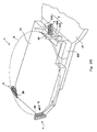
- Fig. 30 is a plan view showing an internal configuration of the end effector device 1, and Fig. 31 is an enlarged view of the driving source unit 600 when viewed from a direction D1 of Fig. 30 .
- the two pitch changing mechanisms 4 provided at the tip end portion of the blade 10 are arranged such that the link members 400 and 410 are inclined relative to a virtual line KS1 connecting the base end portion and tip end portion of the blade 10.
- the pitch changing mechanism 4 of the support unit 3 is provided such that the link members 400 and 410 are perpendicular to the virtual line KS1.
- a direction perpendicular to the virtual line KS1 is denoted by KS2.
- the two pitch changing mechanisms 4 provided at the tip end portion of the blade 10 are spaced apart from each other along the virtual line KS2.
- the driving source unit 600 includes: a motor M; an intermediate gear train 610 that meshes with the motor M; a swing gear 602 located at a downstream end of the intermediate gear train 610; and a swinging member 800 having a swinging center located at a center portion of the swing gear 602.
- the swinging member 800 includes a first leg piece 801 and a second leg piece 810 each extending in a radially outward direction of the swing gear 602 from the swinging center.
- the swinging member 800 swings in a plane perpendicular to the virtual line KS1.
- a tip end portion of the first leg piece 801 is coupled to a free end portion of a first small link 840 via an intervening link 830 whose longitudinal direction extends along the virtual line KS2, the first small link 840 being space apart from the driving source unit 600 along the virtual line KS2.
- a first swinging center shaft 850 is provided at a lower end portion of the first small link 840.
- the first swinging center shaft 850 is connected to the driving shaft 440 of one of the pitch changing mechanisms 4, located at the tip end portion of the blade 10, via a first universal joint 115 provided along the virtual line KS1.
- the first universal joint 115 extends from the first swinging center shaft 850 along the virtual line KS1 and is then inclined relative to the virtual line KS1 toward the pitch changing mechanism 4.
- a tip end portion of the second leg piece 810 of the swinging member 800 is coupled to a free end portion of a second small link 860 via a linear guide member 650 whose longitudinal direction extends along the virtual line KS2, the second small link 860 being located between the swinging member 800 and the first small link 840.
- An interval (KA in Fig. 31 ) between a portion where the linear guide member 650 and the second leg piece 810 are coupled to each other and a portion where the linear guide member 650 and the second small link 860 are coupled to each other is extendable as described below.
- a second swinging center shaft 870 is provided at one end portion of the second small link 860 and connected to the driving shaft 440 of the pitch changing mechanism 4 of the support unit 3.
- a third swinging center shaft 820 provided concentrically with the swinging center of the swinging member 800 is connected to the driving shaft 440 of the other pitch changing mechanism 4, located at the tip end portion of the blade 10, via a second universal joint 125 extending along the virtual line KS1.
- the second universal joint 125 extends from the third swinging center shaft 820 along the virtual line KS1 and is then inclined relative to the virtual line KS1 toward the other pitch changing mechanism 4.
- a first air cylinder 700 is provided outside the first universal joint 115, and a second air cylinder 701 is provided outside the second universal joint 125. Operations of the first and second air cylinders 700 and 701 will be described later. The operations of the motor M and the air cylinders 700 and 701 are controlled by a controller 900 provided outside the blade 10.
- the pitch changing mechanism 4 of the support unit 3 is configured such that the driving shaft 440 is provided at the right end portion of the second link member 410 as shown in Fig. 29A .
- Each of the two pitch changing mechanisms 4 provided at the tip end portion of the blade 10 is configured such that the driving shaft 440 is provided at the left end portion of the second link member 410 as shown in Fig. 28A .
- the rotation direction of the driving shaft 440 of the pitch changing mechanism 4 of the support unit 3 and the rotation direction of each of the driving shafts 440 of the pitch changing mechanisms 4 provided at the tip end portion of the blade 10 need to be opposite to each other.
- Figs. 32A and 32B are diagrams each showing the rotating operation of the swinging member 800.
- the controller 900 supplies electric power to the motor M to cause the motor M to rotate.
- the swinging member 800 swings in the clockwise direction by the rotation of the motor M.
- the third swinging center shaft 820 of the swinging member 800 causes the driving shaft 440 of the pitch changing mechanism 4, located at the tip end portion of the blade 10, to rotate in the clockwise direction.
- the first leg piece 801 of the swinging member 800 causes the first small link 840 to rotate in the clockwise direction via the intervening link 830.
- the first swinging center shaft 850 rotates by the rotation of the first small link 840 to cause the driving shaft 440 of the pitch changing mechanism 4, located at the tip end portion of the blade 10, to rotate in the clockwise direction via the first universal joint 115.
- the second leg piece 810 of the swinging member 800 causes the second small link 860 to rotate in the counterclockwise direction via the linear guide member 650.
- the second swinging center shaft 870 of the second small link 860 causes the driving shaft 440 of the pitch changing mechanism 4 of the support unit 3 to rotate in the counterclockwise direction.
- the linear guide member 650 is located lower than the third swinging center shaft 820 of the swinging member 800.
- the pitches each between the adjacent nail pieces 30 are shortened by the rotation of the driving shaft 440 in the clockwise direction.
- the pitch changing mechanism 4 of the support unit 3 is configured as shown in Fig. 29A , the pitches each between the adjacent nail pieces 30 are shortened by the rotation of the driving shaft 440 in the counterclockwise direction.
- the second small link 860 rotates in the clockwise direction.
- the second swinging center shaft 870 rotates in the clockwise direction to cause the driving shaft 440 of the pitch changing mechanism 4 of the support unit 3 to rotate in the clockwise direction.
- the pitches each between the adjacent nail pieces 30 increase.
- the linear guide member 650 moves from a position lower than the third swinging center shaft 820 to a position higher than the third swinging center shaft 820.
- the distance (KA in Fig. 31 ) between the free end portion of the second leg piece 810 and the free end portion of the second small link 860 changes.
- the linear guide member 650 is configured such that a moving piece 670 that is movable along the virtual line KS2 is provided in a main body 660 extending along the virtual line KS2 (see Fig. 10 ).
- the free end portion of the second small link 860 is attached to one end portion of the main body 660 such that the second small link 860 is rotatable, and the free end portion of the second leg piece 810 is attached to the moving piece 670 such that the second leg piece 810 is rotatable.
- the rotation of the swinging member 800 can be accurately transferred to the second small link 860.
- the free end portion of the second small link 860 and the free end portion of the second leg piece 810 may be connected to each other via a linear motion guide.
- the single motor M causes the three driving shafts 440 to rotate in synchronization with one another to perform the pitch changing operations of the three pitch changing mechanisms 4. With this, it is unnecessary to provide a large number of motors M in accordance with the number of pitch changing mechanisms 4. Thus, the manufacturing cost of the entire end effector device 1 can be suppressed.
- the driving source unit 600 is provided closer to the base end portion of the robot arm than the blade, that is, provided on the second arm 21. With this, the weight of the driving source unit 600 is not applied to the tip end portion of the robot arm. Therefore, the weight on the tip end portion of the robot arm can be reduced, and the tip end portion of the robot arm can operate smoothly.
- Each of the two pitch changing mechanisms 4 located at the tip end portion of the blade 10 is not arranged along the virtual line KS1 (see Fig. 30 ) from the driving source unit 600. Therefore, it is difficult to connect the driving source unit 600 to each of the two pitch changing mechanisms 4 by a linear member. However, the driving source unit 600 can be connected to the two pitch changing mechanisms 4 by using the first and second universal joints 115 and 125. With this, the force of the driving source unit 600 can be transmitted to the two pitch changing mechanisms 4.
- the position of the semiconductor wafer 9 in the horizontal plane may be displaced before or after the rotations. In this case, the semiconductor wafers 9 cannot be accurately conveyed to the processing shelf in the processing booth.
- the first and second guide pins 310 and 500 are caused to be located at positions slightly spaced apart from the peripheral edges of the semiconductor wafers 9. Thus, the positional displacement of each semiconductor wafer 9 in the horizontal plane is prevented.
- the first and second guide pins 310 and 500 are caused to be located at the peripheral edge of the semiconductor wafer 9. Then, the pitches each between the adjacent nail pieces 30 are changed. After the pitches each between the adjacent nail pieces 30 are changed, the first and second guide pins 310 and 500 are pulled back, and the support unit 3 is then moved backward. These operations are controlled by the controller 900 ( Fig. 30 ).
- the first guide pins 310 are provided at the support unit 3, and when the support unit 3 is located at the forward position, the first guide pins 310 are positioned at the peripheral edge of the semiconductor wafer 9.
- the second guide pins 500 project from the lower surface of the blade 10 by the first and second air cylinders 700 and 701.
- a mechanism of causing the second guide pins 500 to project from the lower surface of the blade 10 will be explained.
- Figs. 34A, 34B, and 34C are side views each showing the first air cylinder 700 when viewed from a direction E1 of Fig. 30 .
- the second air cylinder 701 is the same in configuration as the first air cylinder 700.
- the first air cylinder 700 is configured such that a piston 720 is projectable from a housing 710 in a horizontal plane.
- a vertical hole 730 is formed at a tip end portion of the piston 720.
- the second guide pin 500 is horizontally provided under the blade 10 and at a projecting side of the piston 720.
- a contact member 501 is provided at a base end portion of the second guide pin 500.
- a contact roller 510 is provided at an upper end portion of the contact member 501, and a small shaft 520 fitted in the vertical hole 730 projects from the contact member 501.
- a contact wall 130 is provided at the blade 10 so as to correspond to a maximum projection amount of the piston 720.
- the second guide pin 500 is in a horizontal prone posture, and the small shaft 520 is located at a lower end portion of the vertical hole 730.
- the piston 720 projects from the housing 710, and the contact roller 510 of the contact member 500 contacts the contact wall 130. With this, a further movement of the second guide pin 500 in the horizontal direction is prevented.
- Figs. 35A and 35B are side views each showing another mechanism of causing the second guide pin 500 to project from the lower surface of the blade 10.
- the members located on the upper surface of the blade 10 are not shown.
- a base end portion of the second guide pin 500 is attached to a tip end portion of the piston 720 such that the second guide pin 500 is rotatable.
- a torsion spring 540 configured to bias the second guide pin 500 in the counterclockwise direction is provided.
- a plurality of rollers 550 each having a lower end contacting the second guide pin 500 are attached to the lower surface of the blade 10. As shown in Fig.
- the second guide pin 500 in a state where the piston 720 is being pulled back in the housing 710, the second guide pin 500 is being pressed by the rollers 550.
- the second guide pin 500 maintains its prone posture against the biasing force of the torsion spring 540.
- the weight of the driving source is not applied to the tip end portion of the second arm 21, the weight on the tip end portion of the second arm 21 can be reduced, and the tip end portion of the second arm 21 can operate smoothly.
- the driving source may be provided anywhere.
- the driving source may be provided in or on the blade 10.
- a below-described simple mechanism may be used as the mechanism configured to change the pitches each between the adjacent semiconductor wafers 9 by causing the link members to rotate in a vertical plane.
- Figs. 36A, 36B, and 36C are diagrams each showing yet another pitch changing mechanism 4, and Fig. 37 is a diagram when viewed from a direction F1 of Fig. 36B .
- the driving shaft 440 is provided at one end portion (left end portion in Figs. 36A, 36B, and 36C ) of the first link member 400, and a plurality of shaft bodies 470 each having a circular cross section and configured to receive the lower surface of the semiconductor wafer 9 are provided at regular intervals along the longitudinal direction of the first link member 400.
- the shaft body 470 constitutes the "holding portion" of the present invention. In the stand-by positions shown in Fig. 36A , all the shaft bodies 470 are located in the horizontal plane.
- the shaft body 470 located farther from the driving shaft 440 moves up more, and the upper-lower intervals each between the adjacent shaft bodies 470 become larger than those in the case of the stand-by positions.
- the plurality of shaft bodies 470 are provided such that the upper-lower intervals each between the adjacent shaft bodies 470 are equal to one another.
- the shaft bodies 470 reach the intermediate positions.
- the first link member 400 is spaced apart from the semiconductor wafer 9 so as not to rub the semiconductor wafer 9.
- the first link member 400 When the first link member 400 rotates in the counterclockwise direction from the intermediate position by the further rotation of the driving shaft 440, the first link member 400 becomes a vertical state as shown in Fig. 36C .
- the pitches each between the adjacent shaft bodies 470 become maximum.
- the shaft bodies 470 reach the up positions.
- the shaft bodies 470 Until the shaft bodies 470 reach the up positions from the stand-by positions, the shaft bodies 470 move up while rubbing the back surface of the semiconductor wafer 9. Therefore, it is desirable that the shaft bodies 470 be made of a material that causes little friction with the semiconductor wafer 9.
- the present embodiment is not limited to this.
- the pitch changing mechanism 4 shown in Figs. 36A, 36B, and 36C cannot inwardly push the peripheral portions of the semiconductor wafers 9.
- the present embodiment may be configured such that: contacting members 480 that contact the peripheral edges of the semiconductor wafers 9 are respectively provided at the shaft bodies 470; each of pushing springs 490 is provided between the contacting member 480 and the first link member 400; and the contacting members 480 are caused to push the peripheral edges of the semiconductor wafers 9.
- the pitch changing mechanism 4 can be suitably applied to the edge grip type end effector device 1.
- Fig. 39 is a plan view showing a substrate processing device 250 at which the substrate conveying robot 2 shown in Fig. 1 is provided and a substrate processing facility 260 including the substrate processing device 250.
- the substrate processing device 250 is configured such that a below-described second casing 960 is provided at one side portion of a first casing 950 configured to house the substrate conveying robot 2.
- a plurality of foups 230 are provided at the other side portion of the first casing 950.
- the plurality of foups 230 are lined up in a direction perpendicular to a direction in which the semiconductor wafers 9 get in and out of the foups 230.
- a door 980 is provided at a boundary between the second casing 960 and the first casing 950.
- the first casing 950 is maintained at atmospheric pressure whereas the second casing 960 is maintained in a substantially vacuum state by the door 980.
- a delivery region 970 to which a plurality of semiconductor wafers 9 having been conveyed by the substrate conveying robot 2 reach through the door 980 is formed at the second casing 960 side of the door 980.
- a hand device 270 is provided at a middle portion in the second casing 960, and four processing shelves 280 are provided in the second casing 960 so as to surround the hand device 270.
- the hand device 270 holds the plurality of semiconductor wafers 9, having reached the delivery region 970, to convey the semiconductor wafers 9 to the processing shelves 280 and conveys the semiconductor wafer 9, having been subjected to processing in one processing shelf 280, to another processing shelf 280.
- the number of processing shelves 280 in the second casing 960 is not limited to four.
- the substrate processing device 260 includes a plurality of substrate processing devices 250 and performs the entire semiconductor manufacturing process or a part of the semiconductor manufacturing process.
- the processing can be performed under clean circumstances.
- the substrate processing robot 2 holds a plurality of semiconductor wafers 9 in the foup 230 by the end effector device 1 provided at the tip end portion thereof.
- the substrate processing robot 2 rotates around the arm supporting portion 23 to cause the end effector device 1, which is holding the semiconductor wafers 9, to reach the delivery region 970.
- the pitch changing mechanisms 4 see Fig. 2
- the end effector device 1 are activated to shorten the pitches each between the adjacent semiconductor wafers 9.
- the plurality of semiconductor wafers 9 whose pitches have been shortened and which have been conveyed to the delivery region 970 are conveyed to the processing shelves 280 by the hand device 270.
- the present invention is useful for all the end effector devices each including a mechanism configured to support a plurality of plate-shaped members that are spaced apart from one another in an upper-lower direction and parallel to one another and also configured to change the intervals of the plate-shaped members.
Landscapes
- Engineering & Computer Science (AREA)
- Robotics (AREA)
- Mechanical Engineering (AREA)
- Container, Conveyance, Adherence, Positioning, Of Wafer (AREA)
- Manipulator (AREA)
Abstract
Description
- The present invention relates to: an end effector device including a pitch changing mechanism and attached to a tip end portion of a robot arm, the pitch changing mechanism being capable of changing upper-lower intervals of plate-shaped members, more specifically, upper-lower intervals of a plurality of semiconductor wafers used in a semiconductor manufacturing process; a substrate conveying robot including the end effector device; a substrate processing device including the substrate conveying robot; and a substrate processing facility including the substrate processing device.
- A semiconductor manufacturing process includes a step of conveying a plurality of semiconductor wafers at once from a foup that houses the plurality of semiconductor wafers lined up in an upper-lower direction to a processing shelf in which the semiconductor wafers are subjected to predetermined processing. While the semiconductor wafers are being conveyed, the upper-lower interval (hereinafter referred to as a "pitch") between the adjacent semiconductor wafers may be changed. A pitch changing mechanism is used to change this pitch.
- A conventional pitch changing mechanism includes: a plurality of wafer holding trays each configured to receive the entire lower surface of the semiconductor wafer; and vertical shafts respectively provided at base end portions of the wafer holding trays (see PTL 1). Each of the wafer holding trays moves up and down along the vertical shaft and rotates around the vertical shaft in a horizontal plane. The wafer holding trays of the pitch changing mechanism hold the entire lower surfaces of the plurality of semiconductor wafers at a position opposed to the foup to take out the plurality of semiconductor wafers at once. After the pitch changing mechanism has moved in a horizontal direction, the wafer holding trays move down, so that the pitch between the adjacent semiconductor wafers is shortened. Next, the wafer holding trays rotate around the vertical shafts to house all the semiconductor wafers in the processing shelf.
- PTL 1: Japanese Laid-Open Patent Application Publication No.
HEI.5-235147 - The applicants have thought of attaching the end effector device incorporating the pitch changing mechanism to the tip end portion of the robot arm to smoothly transfer the semiconductor wafers from the foup to a processing booth. However, the conventional pitch changing mechanism is large since the wafer holding tray receives the entire lower surface of the semiconductor wafer. Therefore, the conventional pitch changing mechanism is unsuitable for the incorporation into the end effector device.
- An object of the present invention is to provide an end effector device including a mechanism configured to change an interval between semiconductor wafers.
- The present invention is an end effector device attached to a tip end portion of a robot arm, the end effector device including: a blade including a base end portion and a tip end portion; and a support unit provided at the blade and configured to support peripheral portions of a plurality of plate-shaped members such that the plate-shaped members are parallel to one another and spaced apart from one another in an upper-lower direction and also configured to change intervals of the plate-shaped members. Here, the wording "provided so as to be located at the blade" includes both a case where the support unit is directly provided at the blade and a case where the support unit is provided at a portion of the end effector device other than the blade in a manner similar to the above case.
- According to the present invention, a peripheral portion of the plate-shaped member is supported by the support unit. To be specific, since the support unit does not have to receive the entire surface of the plate-shaped member, a portion where the support unit supports the plate-shaped member can be reduced in size. With this, the support unit configured to change the intervals of the plate-shaped members can be reduced in size so as to be suitable for the incorporation into the end effector device. In the present application, the reduction in size also denotes that the size reduction that has been conventionally impossible is realized. That is, the reduction in size in the present application does not just means the size reduction.
- In the above end effector device, a plurality of pitch changing mechanisms are provided at the blade, each of the plurality of pitch changing mechanisms includes holding portions, which are provided so as to be spaced apart from one another in a direction perpendicular to axes of the holding portions, each of the axes extending in one flat plane, and are configured to respectively hold peripheral portions of the plurality of plate-shaped members, each of the plurality of pitch changing mechanisms changes intervals of the plurality of plate-shaped members, the intervals being formed in a direction perpendicular to the one flat plane, at least one of the pitch changing mechanisms is provided at the support unit and is configured to move forward to the tip end portion of the blade and move backward to the base end portion of the blade, and the one of the pitch changing mechanisms holds the plate-shaped members at a position where the one of the pitch changing mechanisms has moved forward to the tip end portion of the blade and cancels the holding of the plate-shaped members at a position where the one of the pitch changing mechanisms has moved backward to the base end portion of the blade.
- According to the present invention, when one pitch changing mechanism moves backward, the holding of the plate-shaped members by the holding portions of this pitch changing mechanism is cancelled. With this, the plurality of plate-shaped members whose intervals have been changed can be easily passed to the next processing stage. In the following explanation, a configuration in which the pitch changing mechanism presses the peripheral portion of the plate-shaped member in a direction connecting the base end and tip end of the blade to hold the plate-shaped member is called an edge grip type.
- In the present invention, the incorporated support unit has a pitch changing function and supports the peripheral portions of the plate-shaped members. With this, a mechanism configured to change the pitches in the end effector device can be reduced in size.
-
- [
Fig. 1] Fig. 1 is a perspective view of an entire substrate conveying robot. - [
Fig. 2] Fig. 2 is an enlarged perspective view of the end effector device. - [
Fig. 3] Fig. 3 is a plan view of the end effector device shown inFig. 2 . - [
Fig. 4] Fig. 4 is a perspective view of a nail piece. - [
Fig. 5] Fig. 5 is a side view showing a state where a semiconductor wafer is held by the nail pieces. - [
Fig. 6] Fig. 6 is a diagram showing another type of nail pieces. - [
Figs. 7A and 7B] Figs. 7A and 7B are partial cutaway views each showing a side surface of a pitch changing mechanism according to one embodiment.Fig. 7A shows an initial state where the pitches are large, andFig. 7B shows a state where the pitches are small. - [
Fig. 8] Fig. 8 is a plan view of the nail piece located at a lowest position when viewed from a direction A1 ofFig. 7A . - [
Figs. 9A and 9B] Figs. 9A and 9B are partial cutaway views each showing the side surface of the pitch changing mechanism according to another embodiment.Fig. 9A shows an initial state where the pitches are large, andFig. 9B shows a state where the pitches are small. - [
Figs. 10A and 10B] Figs. 10A and 10B are partial cutaway views each showing the side surface of the pitch changing mechanism according to still another embodiment.Fig. 10A shows an initial state where the pitches are large, andFig. 10B shows a state where the pitches are small. - [
Fig. 11] Fig. 11 is a perspective view of the nail piece used in the pitch changing mechanism ofFig. 10 . - [
Figs. 12A and 12B] Figs. 12A and 12B are partial cutaway views each showing the side surface of the pitch changing mechanism according to yet another embodiment.Fig. 12A shows an initial state where the pitches are large, andFig. 12B shows a state where the pitches are small. - [
Fig. 13] Fig. 13 is a side view of a cylindrical body used in the pitch changing mechanism ofFig. 12 . - [
Figs. 14A and 14B] Figs. 14A and 14B are partial cutaway views each showing the side surface of the pitch changing mechanism according to still another embodiment.Fig. 14A shows an initial state where the pitches are large, andFig. 14B shows a state where the pitches are small. - [
Figs. 15A and 15B] Figs. 15A and 15B are partial cutaway views each showing the side surface of the pitch changing mechanism according to yet another embodiment.Fig. 15A shows an initial state where the pitches are large, andFig. 15B shows a state where the pitches are small. - [
Figs. 16A and 16B] Figs. 16A and 16B are partial cutaway views each showing the side surface of the pitch changing mechanism according to still another embodiment.Fig. 16A shows an initial state where the pitches are large, andFig. 16B shows a state where the pitches are small. - [
Figs. 17A and 17B] Figs. 17A and 17B are partial cutaway views each showing the side surface of the pitch changing mechanism according to yet another embodiment.Fig. 17A shows an initial state where the pitches are large, andFig. 17B shows a state where the pitches are small. - [
Fig. 18] Fig. 18 is a plan view of the pitch changing mechanism according to still another embodiment. - [
Fig. 19] Fig. 19 is a perspective view showing major portions of the pitch changing mechanism shown inFig. 18 . - [
Figs. 20A and 20B] Figs. 20A and 20B are side views each showing the pitch changing mechanism when viewed from a direction B1 ofFig. 18 .Fig. 20A shows an initial state where the pitches are large, andFig. 20B shows a state where the pitches are small. - [
Figs. 21A to 21C] Figs. 21A and 21B are side views each showing the pitch changing mechanism according to yet another embodiment.Fig. 21A shows an initial state where the pitches are large, andFig. 21B shows a state where the pitches are small.Fig. 21C is a cross-sectional view taken along line C1-C1 ofFig. 21A , which is viewed from a back surface of the pitch changing mechanism. - [
Figs. 22A and 22B] Figs. 22A and 22B are partial cutaway views each showing the side surface of the pitch changing mechanism according to still another embodiment.Fig. 22A shows an initial state where the pitches are large, andFig. 22B shows a state where the pitches are small. - [
Figs. 23A and 23B] Figs. 23A and 23B are partial cutaway views each showing the side surface of the pitch changing mechanism according to yet another embodiment.Fig. 23A shows an initial state where the pitches are large, andFig. 23B shows a state where the pitches are small. - [
Fig. 24] Fig. 24 is an exploded perspective view of the pitch changing mechanism according to still another embodiment. - [
Figs. 25A and 25B] Figs. 25A and 25B are cross-sectional views each showing the pitch changing mechanism when viewed from a direction D1 ofFig. 24 .Fig. 25A shows an initial state where the pitches are large, andFig. 25B shows a state where the pitches are small. - [
Fig. 26] Fig. 26 is an enlarged perspective view of the end effector device according to another embodiment. - [
Figs. 27A and 27B] Figs. 27A and 27B are plan views each showing a moving operation of a support unit shown inFig. 26 . - [
Figs. 28A to 28C] Figs. 28A to 28C are diagrams each showing a rotating operation of the pitch changing mechanism shown inFig. 26 and are diagrams each viewed from a direction B ofFig. 26 . - [
Figs. 29A and 29B] Figs. 29A and 29B are diagrams each showing the rotating operation of another pitch changing mechanism. - [
Fig. 30] Fig. 30 is a plan view showing an internal mechanism of the end effector device. - [
Fig. 31] Fig. 31 is an enlarged view of a driving source unit when viewed from a direction D1 ofFig. 30 . - [
Figs. 32A and 32B] Figs. 32A and 32B are diagrams each showing a rotating operation of a swinging member. - [
Fig. 33] Fig. 33 is a diagram showing the configuration of a linear guide member. - [
Figs. 34A to 34C] Figs. 34A to 34C are side views each showing a first air cylinder when viewed from a direction E1 ofFig. 30 . - [
Figs. 35A and 35B] Figs. 35A and 35B are side views each showing another mechanism of causing a second guide pin to project from a lower surface of a blade. - [
Figs. 36A to 36C] Figs. 36A to 36C are diagrams each showing yet another pitch changing mechanism. - [
Fig. 37] Fig. 37 is a diagram when viewed from a direction F1 ofFig. 36B . - [
Fig. 38] Fig. 38 is a diagram showing still another pitch changing mechanism. - [
Fig. 39] Fig. 39 is a plan view showing a substrate processing device including the substrate conveying robot ofFig. 1 and a substrate processing facility including the substrate processing device. - Hereinafter, one embodiment of the present invention will be explained in detail in reference to the drawings. The present invention relates to an end effector device attached to a tip end portion of an arm of a substrate conveying robot. First, the conveying robot will be explained wholly. In the embodiments of the present invention, a horizontal plane is used as one example of "one flat plane" in the present invention. In addition, a circular plate-shaped semiconductor wafer is used as one example of a plate-shaped member conveyed by the conveying robot. However, the plate-shaped member is not limited to the semiconductor wafer. For example, the plate-shaped member may be a glass substrate processed in a semiconductor process and used for a thin liquid crystal display or an organic EL display. The semiconductor wafer is a substrate material of a semiconductor device, and examples thereof include a silicon wafer, a silicon carbide wafer, and a sapphire wafer. Further, the semiconductor wafer does not have to be a material, and a circuit and/or a structure may be formed on the plate-shaped member. The shape of the semiconductor wafer is not limited to a circular shape.
- Examples of the processing of the semiconductor wafer include a heat treatment and film formation performed in a processing booth. A plurality of semiconductor wafers before the processing are housed in a foup (Front Opening Unified Pod), located away from the processing booth, such that each of the semiconductor wafers is in a horizontal posture, and the semiconductor wafers are lined up in an upper-lower direction.
- A processing shelf for semiconductor wafer processing is provided in the processing booth. The processing shelf holds a plurality of semiconductor wafers such that each of the semiconductor wafers is in a horizontal posture, and the semiconductor wafers are lined up in the upper-lower direction. At the time of the processing, a plurality of semiconductor wafers are taken out from the foup at once to be conveyed to the processing shelf. Here, the pitch between the adjacent semiconductor wafers in the processing shelf is different from the pitch between the adjacent semiconductor wafers in the foup in some cases. Specifically, the pitch in the processing shelf is shorter than the pitch in the foup in some cases. In such a case, used is a pitch changing mechanism configured to take out the plurality of semiconductor wafers from the foup and change the pitches while the plurality of semiconductor wafers are being conveyed to the processing shelf. This is the same as conventional cases.
- Components for housing the semiconductor wafers are not limited to the foup and the processing shelf. To be specific, any components may be used as long as the semiconductor wafers are housed in the components such that the pitches of the semiconductor wafers in one of the components are different from those of the semiconductor wafers in the other component.
-
Fig. 1 is a perspective view of an entiresubstrate conveying robot 2. Thesubstrate conveying robot 2 is a robot configured to convey a plurality of semiconductor wafers lined up in the upper-lower direction. One example of thesubstrate conveying robot 2 is a so-called horizontally articulated three-axis robot. Thesubstrate conveying robot 2 is configured such that: anarm supporting portion 23 capable of moving up and down is provided on a base 22 fixed to a semiconductor processing equipment; and one end portion of afirst arm 20 extending in a horizontal direction is attached to an upper end portion of thearm supporting portion 23. Thefirst arm 20 is provided so as to be rotatable relative to thearm supporting portion 23, and one end portion of asecond arm 21 is pivotally supported by the other end portion of thefirst arm 20. - A below-described
end effector device 1 is attached to a terminal end portion of thesecond arm 21. Since thefirst arm 20 rotates relative to thearm supporting portion 23, and thesecond arm 21 rotates relative to thefirst arm 20 in the horizontal plane, theend effector device 1 moves in the horizontal plane. The end effector device can move in a height direction by the upward and downward movements of thearm supporting portion 23. - The
substrate conveying robot 2 may be included in a substrate processing device. The substrate processing device may be included in a substrate processing facility. The substrate processing device and the substrate processing facility will be described later. - The
end effector device 1 includes: ablade 10 having a base end portion attached to a tip end portion of thesecond arm 21; and a plurality of support units extending upward from the blade 10 (for example, inFig. 1 , threesupport units support units semiconductor wafers 9 such that each of thesemiconductor wafers 9 is in a horizontal posture, thesemiconductor wafers 9 are spaced apart from one another in the upper-lower direction. Theend effector device 1 configured such that thesupport units 3 are provided on the lower surface of theblade 10 or on both upper and lower surfaces of theblade 10 is also included in the technical scope of the present invention. However, for convenience of explanation, in the following example, thesupport units 3 extend upward from theblade 10. -
Fig. 2 is an enlarged perspective view of theend effector device 1, andFig. 3 is a plan view of theend effector device 1. Two of the threesupport units end support units 3 located at a tip end portion of theblade 10, and the other is a baseend support unit 3a located at the base end portion of theblade 10. Anelongated hole 11 extending from the base end portion of theblade 10 toward the tip end side is formed on the base end portion of theblade 10. The baseend support unit 3a is provided on the tip end portion of thesecond arm 21 to project upward from theblade 10 through theelongated hole 11. This configuration in which the baseend support unit 3a is provided on the tip end portion of thesecond arm 21 to project upward from theblade 10 through theelongated hole 11 is also included in the configuration in which "the baseend support unit 3a is provided so as to be located at theblade 10". The baseend support unit 3 a moves on the tip end portion of thesecond arm 21 or on theblade 10 by a plunger (not shown) provided at thesecond arm 21. Specifically, the baseend support unit 3a moves between a forward position where the baseend support unit 3a has moved toward the tip end of theblade 10 and a backward position where the baseend support unit 3a has moved toward the base end portion of theblade 10 from the forward position. - For convenience of explanation, the above embodiment has explained a case where the tip
end support units 3 are fixed to theblade 10, and the baseend support unit 3a moves along theelongated hole 11. However, instead of this, one or both of the tipend support units 3 may be moved in a direction toward the center of thesemiconductor wafer 9 or toward the base end portion of theblade 10. That is, the distance between thesupport units 3 may be shortened. - Each of the
support units nail pieces 30 arranged so as to be spaced apart from one another in the upper-lower direction and each configured to support a peripheral portion of thesemiconductor wafer 9; and apitch changing mechanism 4 configured to change upper-lower intervals of the plurality ofnail pieces 30. Threenail pieces 30, located at the same height, of thesupport units semiconductor wafer 9. - As shown in
Fig. 3 , the threenail pieces 30, located at the same height, of thesupport units semiconductor wafer 9. Since the horizontal plane at which thesemiconductor wafer 9 should be located is determined by the threenail pieces 30, thesemiconductor wafer 9 is substantially horizontally, stably supported by the threenail pieces 30. -
Fig. 4 is a perspective view of thenail piece 30. Thenail piece 30 is configured to have two stages such that a receivingpiece 32 projects laterally from a lower end portion of amain body 31. An upper surface of the receivingpiece 32 forms a receivingsurface 33 that receives a lower surface of the peripheral portion of thesemiconductor wafer 9. An inner side surface of themain body 31 forms acontact surface 34 that is substantially perpendicular to the receivingsurface 33 and contacts a peripheral end surface of thesemiconductor wafer 9. Thenail piece 30 is made of synthetic resin. However, the present embodiment is not limited to this. It is preferable that thenail piece 30 be made of a material that does not damage thesemiconductor wafer 9. -
Fig. 5 is a side view showing a state where thesemiconductor wafer 9 is held by thenail pieces 30. As described above, thenail piece 30 is the edge grip type that stably holds thesemiconductor wafer 9 by causing the contact surfaces 34 to inwardly push the peripheral edge of thesemiconductor wafer 9. - When the
support unit 3a is located at the forward position, thenail pieces 30 located at the same height hold thesemiconductor wafer 9. With this, the position of thesemiconductor wafer 9 in the horizontal plane is stabilized. Further, even if the entireend effector device 1 is conveyed at high speed, thesemiconductor wafer 9 is not displaced. As above, the edge griptype nail piece 30 is advantageous in that thesemiconductor wafer 9 is stably held and conveyed. However, thenail piece 30 may have another configuration shown inFig. 6 . -
Fig. 6 is a side view showing another type ofnail pieces 30. Thenail piece 30 includes: afirst oblique surface 320 that is inclined inward and downward from an upper end portion of themain body 31; and asecond oblique surface 330 that is formed at a lower side of thefirst oblique surface 320, is continuous with thefirst oblique surface 32, is inclined inward and downward, and has an inclination angle smaller than that of thefirst oblique surface 32. The peripheral portion of thesemiconductor wafer 9 is placed at and held by a boundary SM between thefirst oblique surface 320 and thesecond oblique surface 330 at an inner side of eachnail piece 30. - According to this configuration, when the
semiconductor wafer 9 is held by thenail piece 30, thesemiconductor wafer 9 slides on thefirst oblique surface 320 of thenail piece 30 to be placed at the boundary SM between thefirst oblique surface 320 and thesecond oblique surface 330 of thenail piece 30. With this, the horizontal position and horizontal posture of thesemiconductor wafer 9 relative to thepitch changing mechanism 4 are corrected, so that thesemiconductor wafer 9 is stably held. Since thenail piece 30 and thesemiconductor wafer 9 line-contact each other, an area of contact between thenail piece 30 and thesemiconductor wafer 9 is small. With this, the adhesion of foreign matters to thesemiconductor wafer 9 decreases. - The
end effector device 1 is located at a position opposed to the foup that houses a plurality ofsemiconductor wafers 9 such that thesemiconductor wafers 9 are spaced apart from one another in the upper-lower direction. A plurality of semiconductor wafers are transferred from the foup to theend effector device 1 by thesubstrate conveying robot 2 while maintaining a state where the semiconductor wafers are spaced apart from one another in the upper-lower direction. The baseend support unit 3a moves from the backward position to the forward position by the plunger to hold thesemiconductor wafers 9. - When the base
end support unit 3a ofFig. 2 is located at the forward position, the receivingsurface 33 of eachnail piece 30 of the baseend support unit 3a receives the lower surface of the peripheral portion of thesemiconductor wafer 9, and thecontact surface 34 of eachnail piece 30 of the baseend support unit 3a pushes the peripheral end surface of thesemiconductor wafer 9 in a forward direction. The peripheral end surface of thesemiconductor wafer 9 is pushed by the contact surfaces 34 of thenail pieces 30, located at the same height, of the tipend support units 3. Thus, the peripheral portion lower surface and peripheral end surface of thesemiconductor wafer 9 are held by the threenail pieces 30 in theend effector device 1. To be specific, only a part of the lower surface of the peripheral portion of thesemiconductor wafer 9 is received by thenail pieces 30, and thenail pieces 30 do not cover the entire lower surface of thesemiconductor wafer 9. - In this state, the
first arm 20 and the second arm 21 (seeFig. 1 ) rotate, and thearm supporting portion 23 moves up and down. Thus, the plurality ofsemiconductor wafers 9 held by theend effector device 1 are conveyed to be in front of the processing shelf (not shown) in the processing booth for semiconductors. Supporting portions (not shown) each configured to receive the lower surface of thesemiconductor wafer 9 are provided in the processing shelf. - When the
end effector device 1 has conveyed the plurality ofsemiconductor wafers 9 to the semiconductor processing booth, the supporting portions are moved so as to be respectively opposed to the lower surfaces of thesemiconductor wafers 9, and then respectively contact lower surface exposed portions of thesemiconductor wafers 9. When the baseend support unit 3a has moved to the backward position, the receiving surfaces 33 of thenail pieces 30 of the baseend support unit 3a are separated from the lower surfaces of the peripheral portions of thesemiconductor wafers 9. Thus, thesemiconductor wafers 9 are not supported by thenail pieces 30 any more. The plurality ofsemiconductor wafers 9 are supported by the supporting portions to be conveyed to the processing shelf in the processing booth. Then, thesemiconductor wafers 9 are subjected to the heat treatment and/or the film formation. Thearm supporting portion 23 moves up and down, and thefirst arm 20 and thesecond arm 21 rotate. Thus, theend effector device 1 returns to the position opposed to the foup. - As with conventional cases, while a plurality of semiconductor wafers are conveyed from the foup to the processing shelf of the processing booth, it is necessary to change the upper-lower interval between the adjacent semiconductor wafers, more specifically, it is necessary to reduce the upper-lower interval. As described above, the
support unit 3 includes thepitch changing mechanism 4 configured to change the upper-lower intervals of the plurality ofnail pieces 30. The following will explain various types ofpitch changing mechanisms 4. For convenience of explanation, thepitch changing mechanism 4 of the tipend support unit 3 standing on theblade 10 will be explained. The samepitch changing mechanism 4 is provided at the baseend support unit 3 a. -
Figs. 7A and 7B are partial cutaway views each showing a side surface of thepitch changing mechanism 4 according toEmbodiment 1.Fig. 7A shows an initial state where the pitches are large, andFig. 7B shows a state where the pitches are small. - A
piston pin 50 having a circular cross section is provided on theblade 10 so as to be able to move up and down, and aflange 51 is attached to an upper end portion of thepiston pin 50. Aspiral coil spring 40 extending in the upper-lower direction is fitted on thepiston pin 50 and is configured such that spring pitches thereof are equal to one another. Thecoil spring 40 is a single compression coil spring, and the plurality ofnail pieces 30 are arranged at an outer peripheral portion of thecoil spring 40 so as to be spaced apart from one another in the upper-lower direction such that a tip end portion of eachnail piece 30 faces a center portion of thesemiconductor wafer 9. Specifically, fivenail pieces 30 are provided, and thenail piece 30 located at a lowest position contacts theblade 10 and does not move up or down. The other fournail pieces 30 move up and down. The number ofnail pieces 30 is not limited to five. - While the
pitch changing mechanism 4 in the initial state is conveyed to the processing booth, the intervals each between theadjacent nail pieces 30 are equally shortened from 10 mm to 6 mm. In the following explanation, the intervals are shortened by pushing down thenail pieces 30 located at higher positions. To be specific, thenail piece 30 located above and adjacent to thenail piece 30 located at the lowest position is pushed down by 4 mm, but thenail piece 30 located at the highest position is pushed down by 16 mm. A lowering distance of thenail piece 30 located at a higher position becomes larger. Of course, the intervals each between thenail pieces 30 may be shortened by pushing down thenail pieces 30 located at lower positions. Both pushing up and pushing down of thenail pieces 30 may be performed. - In the present embodiment, the
piston pin 50 serves as a part of anoperating mechanism 5 configured to cause thecoil spring 40 to elastically deform in the upper-lower direction to change the intervals each between theadjacent nail pieces 30. One example of a mechanism configured to cause thepiston pin 50 to move up and down is a mechanism configured such that thepiston pin 50 is connected to a solenoid or an air cylinder. - In the initial state shown in
Fig. 7A , thecoil spring 40 is in a free length state or is being slightly pushed downward by theflange 51. The upper-lower interval between theadjacent nail pieces 30 is equal to one spring pitch, and thenail pieces 30 and thecoil spring 40 are integrally made of synthetic resin. Thenail piece 30 located at the highest position is in contact with a lower surface of theflange 51. - When the
piston pin 50 moves down from the initial state shown inFig. 7A , theflange 51 presses thecoil spring 40 downward, and thecoil spring 40 contracts against an elastic biasing force until the adjacent coils tightly contact each other. Since distances each between the adjacent pitches are shortened, the intervals each between theadjacent nail pieces 30 are also shortened. As described above, since thenail pieces 30 receive the lower surfaces of the peripheral portions of thesemiconductor wafers 9, the intervals each between thesemiconductor wafers 9 adjacent to each other in the upper-lower direction are also shortened. With this, the upper-lower intervals of the plurality of semiconductor wafers taken out from the foup are shortened, and the plurality of semiconductor wafers are transferred to the processing booth. After the plurality of semiconductor wafers are taken out in the processing booth, theend effector device 1 including thepitch changing mechanism 4 returns to the position opposed to the foup. At this time, thepiston pin 50 moves up from the state shown inFig. 7B to the state shown inFig. 7A . Thecoil spring 40 expands upward by an elastic returning force. Thus, the upper-lower intervals each between theadjacent nail pieces 30 increase, and thepitch changing mechanism 4 returns to the initial state. To be specific, even though thepiston pin 50 does not pull up thecoil spring 40, thecoil spring 40 returns to the initial state. Of course, the present embodiment may be configured such that thecoil spring 40 is attached to theflange 51 and is pulled up by thepiston pin 50. - Here, since the
piston pin 50 has the circular cross section, there is a possibility that thecoil spring 40 and thenail pieces 30 unexpectedly rotate around thepiston pin 50. In this case, there is a possibility that thenail pieces 3 rotate so as to be away from the lower surface of thesemiconductor wafer 9 and therefore cannot receive thesemiconductor wafer 9. In consideration of this, a component for rotation stop is provided on theblade 10 as shown inFig. 8 . -
Fig. 8 is a plan view of thenail piece 30 located at the lowest position when viewed from a direction A1 shown inFig. 7A . Arotation stop piece 12 is provided on theblade 10 so as to surround thenail piece 30 located at the lowest position, and thenail piece 30 located at the lowers position is fitted in a concave 13 of therotation stop piece 12. A side portion of thenail piece 30 contacts an inner side wall of the concave 13, so that thenail piece 30 located at the lowest position is prevented from unexpectedly rotating around thepiston pin 50. Since thenail pieces 30 and thecoil spring 40 are formed integrally, the rotation of thecoil spring 40 around thepiston pin 50 is also prevented. - The
nail pieces 30 support only a part of the lower surface of the peripheral portion of thesemiconductor wafer 9 and does not cover the entire lower surface of thesemiconductor wafer 9. Therefore, thepitch changing mechanism 4 can be made smaller and lighter than a conventionalpitch changing mechanism 4 configured to support the entire lower surface of thesemiconductor wafer 9. Therefore, thepitch changing mechanism 4 is suitably incorporated in theend effector device 1 attached to the tip end portion of the robot arm. -
Figs. 9A and 9B are partial cutaway views each showing the side surface of thepitch changing mechanism 4 according toEmbodiment 2.Fig. 9A shows an initial state where the pitches are large, andFig. 9B shows a state where the pitches are small. Thepitch changing mechanism 4 of the present embodiment is configured such that: the spring pitch thereof is made shorter than, to be specific, is set to half the spring pitch of thecoil spring 40 of thepitch changing mechanism 4 shown inFig. 7A ; and onenail piece 30 is arranged for each spring pitch. In this example, when thepiston pin 50 moves down from the initial state shown inFig. 9A , thecoil spring 40 contracts, and the adjacent coils tightly contact each other. Thus, the intervals each between theadjacent nail pieces 30 are shortened, so that as shown inFig. 9B , the intervals each between thesemiconductor wafers 9 adjacent to each other in the upper-lower direction are also shortened. With this, the upper-lower intervals of the plurality of semiconductor wafers taken out from the foup are shortened, and the plurality of semiconductor wafers are transferred to the processing booth. Subsequent operations of thepitch changing mechanism 4 are the same as those ofEmbodiment 1, so that explanations thereof are omitted. -
Figs. 10A and 10B are partial cutaway views each showing the side surface of thepitch changing mechanism 4 according toEmbodiment 3.Fig. 10A shows an initial state where the pitches are large, andFig. 10B shows a state where the pitches are small. In the present embodiment, thepiston pin 50 is a square shaft having a rectangular cross section, and a plurality ofcoil springs 40 are fitted on thepiston pin 50 so as to be stacked at plural stages. The coil springs 40 herein are compression coil springs as withEmbodiments coil spring 40 of each ofEmbodiments nail piece 30 is attached to the upper end portion of each of the coil springs 40, and the tip end portion of eachnail piece 30 faces the center portion of thesemiconductor wafer 9. Acertain nail piece 30 and thecoil spring 40 contacting the upper surface of thecertain nail piece 30 are joined to each other, that is, the coil springs 40 adjacent to each other in the upper-lower direction are joined to each other via thenail piece 30. As withEmbodiment 1, thenail pieces 30 adjacent to each other in the upper-lower direction are arranged so as to be spaced apart from each other in the upper-lower direction. Eachnail piece 30 is fitted on thepiston pin 50 to be moved up and down. In the initial state where the intervals each between theadjacent nail pieces 30 are large as shown inFig. 10A , each of the coil springs 40 is in the free length state or is being slightly pushed downward. Fivenail pieces 3 are provided. Thenail piece 30a located at the lowest position is a fixed nail piece fixed to theblade 10, and the other fournail pieces 30 are movable nail pieces that move up and down. - When the
piston pin 50 moves down from the initial state shown inFig. 10A , the coil springs 40 are pressed downward by theflange 51 to contract against upward elastic biasing forces until the adjacent coils tightly contact each other. Since the distances each between the adjacent pitches of thecoil spring 40 are shortened, the intervals each between theadjacent nail pieces 30 are also shortened. Thus, as shown inFig. 10B , the intervals each between thesemiconductor wafers 9 adjacent to each other in the upper-lower direction are also shortened. With this, the upper-lower intervals of the plurality of semiconductor wafers taken out from the foup are shortened, and the plurality of semiconductor wafers are transferred to the processing booth. - When the
end effector device 1 including thepitch changing mechanism 4 has returned from the processing booth to the position opposed to the foup, thepiston pin 50 moves up as shown inFig. 10A . The coil springs 40 having been pressed downward expand upward by the elastic returning forces, so that the upper-lower intervals each between theadjacent nail pieces 30 increase. - The
nail piece 30 and thecoil spring 40 may be formed integrally but do not have to be formed integrally. Therefore, thenail piece 30 and thecoil spring 40 may be made of different materials. For example, thenail piece 30 may be made of synthetic resin, and thecoil spring 40 may be formed by a metal wire. As thecoil spring 40, a general-purpose product formed by the metal wire is commercially available. Therefore, thepitch changing mechanism 4 can be manufactured at low cost by using thecoil spring 40 that is the general-purpose product and is made of metal. - Since the
piston pin 50 is a square shaft, the rotation of thenail piece 30 around thepiston pin 50 can be prevented by thepiston pin 50.Fig. 11 is a perspective view of thenail piece 30 used in thepitch changing mechanism 4 ofEmbodiment 3. A throughhole 35 having a rectangular shape is formed on themain body 31 of thenail piece 30 so as to penetrate themain body 31 in the upper lower direction. Thepiston pin 50 is fitted in the throughhole 35 such that thenail piece 30 is slidable. With this, thenail piece 30 is prevented from unexpectedly rotating around thepiston pin 50, and thenail piece 30 surely supports the lower surface of thesemiconductor wafer 9. InEmbodiments piston pin 50 may be formed as a square shaft, and an inner opening of thecoil spring 40 that is fitted on thepiston pin 50 may be formed in a rectangular shape. That is, thepiston pin 50 and thecoil spring 40 may be formed in any shape as long as relative rotations thereof are prevented. -
Figs. 12A and 12B are partial cutaway views each showing the side surface of thepitch changing mechanism 4 according toEmbodiment 4.Fig. 12A shows an initial state where the pitches are large, andFig. 12B shows a state where the pitches are small.Fig. 13 is a side view of acylindrical body 8 used in thepitch changing mechanism 4. In the present embodiment, thenail piece 30a located at the lowest position is a fixed nail piece fixed to theblade 10, and the other fournail pieces 30 are movable nail pieces. - The
pitch changing mechanism 4 includes thecylindrical body 8 provided on theblade 10, and a nail piece guideshaft 81 is provided inside thecylindrical body 8 so as to extend in the upper-lower direction. Thecylindrical body 8 is provided so as to be rotatable around the nail piece guideshaft 81 in the horizontal plane. A plurality ofspiral grooves 80 are formed on a peripheral surface of thecylindrical body 8 so as to penetrate the outer and inner sides of thecylindrical body 8 and respectively correspond to thenail pieces 30. An upper-lower length of a portion of thespiral groove 80 is called a spiral pitch, the portion corresponding to one circumference of the outer peripheral surface of thecylindrical body 8. The spiral pitch of thespiral groove 80 located at a higher position is larger, and the spiral pitch of thespiral groove 80 located at a lower position is smaller. This is because, as described above, to equally shorten the intervals each between theadjacent nail pieces 30, the lowering distance of thenail piece 30 located at a higher position needs to be larger. - The base end portion of each
nail piece 30 is fitted on the nail piece guideshaft 81, and the tip end portion thereof penetrates thespiral groove 80 to face the center portion of thesemiconductor wafer 9. The nail piece guideshaft 81 is a square shaft, and as shown inFig. 11 , the throughhole 35 having a rectangular shape is formed on themain body 31 of thenail piece 30 of the present embodiment. Therefore, even if thecylindrical body 8 rotates, thenail pieces 30 do not rotate and are just allowed to move up and down. - There are various mechanisms configured to cause the
cylindrical body 8 to rotate. As shown inFigs. 12A and 12B , one example is that: one end portion of atiming belt 82 is wound around the lower end portion of thecylindrical body 8; and the other end portion of thetiming belt 82 is connected to a direct drive device (not shown), such as a motor or air cylinder provided at thesecond arm 21. Such a motor or air cylinder may be provided at theblade 10. - As shown in
Fig. 12A , from the initial state where thenail pieces 30 adjacent to each other in the upper-lower direction are spaced apart from each other by a predetermined interval, thecylindrical body 8 is rotated in a clockwise direction when viewed from above. Thenail pieces 30 move down along thespiral grooves 80. As described above, the spiral pitch of thespiral groove 80 located at a higher position is larger, and the spiral pitch of thespiral groove 80 located at a lower position is smaller. Therefore, the lowering distance of thenail piece 30 located at the highest position is the largest, and the lowering distance of thenail piece 30 located at a lower position becomes smaller. In a state where the downward movement of thenail piece 30 located at the highest position has been completed, as shown inFig. 12B , the intervals each between theadjacent nail pieces 30 are respectively shorter than those in the initial state shown inFig. 12A . With this, the upper-lower intervals of the plurality of semiconductor wafers taken out from the foup are shortened, and the plurality of semiconductor wafers are transferred to the processing booth. - After the plurality of
semiconductor wafers 9 are taken out in the processing booth, theend effector device 1 including thepitch changing mechanism 4 returns to the initial state so as to be opposed to the foup. At this time, thecylindrical body 8 is rotated in a counterclockwise direction when viewed from above, and thenail pieces 30 are moved up from the state shown inFig. 12B to the state shown inFig. 12A . Thepitch changing mechanism 4 returns to the initial state. - The present embodiment may be configured such that: the nail piece guide shaft is provided outside the
cylindrical body 8; and thenail pieces 30 are fitted in thespiral grooves 80 of the cylindrical body 8 (seeFig. 13 ; the nail piece guide shaft is not shown inFig. 13 ). In this case, thespiral groove 80 does not have to penetrate the outside and inside of thecylindrical body 8 and may be formed on the peripheral surface of thecylindrical body 8. -
Figs. 14A and 14B are partial cutaway views each showing the side surface of thepitch changing mechanism 4 according toEmbodiment 5 and showing another example of theoperating mechanism 5 configured to cause thenail pieces 30 to move up and down.Fig. 14A shows an initial state where the pitches are large, andFig. 14B shows a state where the pitches are small. - The
operating mechanism 5 includes: a hollow fixedshaft 6 standing on theblade 10; and anextendable shaft 60, whose lower surface is open and which is fitted on the fixedshaft 6 from an upper side of the fixedshaft 6 so as to be able to move up and down. As withEmbodiment 1, thecoil spring 40 including the plurality ofnail pieces 30 respectively corresponding to the pitches are fitted outside the fixedshaft 6 and theextendable shaft 60. Aflange 61 is provided at an upper end portion of theextendable shaft 60, and thenail piece 30 located at the highest position is attached to theflange 61. With this, when theextendable shaft 60 moves up or down, thecoil spring 40 expands or contracts, so that the upper-lower intervals each between theadjacent nail pieces 30 change. The present embodiment may be configured such that: thenail piece 30 located at the highest position is not attached to theflange 61 and is pressed by the biasing force of thecoil spring 40 to contact theflange 61. - The
operating mechanism 5 includes a cylinder (not shown) located at the base end portion side of thesecond arm 21, and the cylinder and theflange 61 are connected to each other via awire 62 extending through the fixedshaft 6 and theextendable shaft 60. Thewire 62 extends downward from the lower surface of theflange 61. After that, in theblade 10, thewire 62 winds around apulley 63 provided under the fixedshaft 6, and then extends horizontally to be connected to the cylinder. A rotational center axis of thepulley 63 is substantially perpendicular to thewire 62 extending between thepulley 63 and the cylinder. - When the cylinder horizontally pulls the
wire 62 from the initial state shown inFig. 14A , the pulling movement of thewire 62 is converted into a downward pulling movement by thepulley 63, so that theflange 61 is pulled downward. Thecoil spring 40 is pressed downward against the elastic biasing force to contract until the adjacent coils tightly contact each other. As a result, as shown inFig. 14B , the intervals each between theadjacent nail pieces 30 become shorter than those in the initial state shown inFig. 14A . With this, the upper-lower intervals of the plurality of semiconductor wafers taken out from the foup are shortened, and the plurality of semiconductor wafers are transferred to the processing booth. - After the plurality of
semiconductor wafers 9 are taken out in the processing booth, theend effector device 1 including thepitch changing mechanism 4 returns to the position opposed to the foup. At this time, the cylinder cancels the pulling operation of thewire 62. Thecoil spring 40 moves up by the elastic returning force. Thus, the intervals each between theadjacent nail pieces 30 increase, and thepitch changing mechanism 4 returns to the initial state. - In the present embodiment, the cylinder that is a driving source of the
operating mechanism 5 is provided outside theblade 10 and at the base end portion side of thesecond arm 21. To be specific, the cylinder is not provided in or on theblade 10. Therefore, thepitch changing mechanism 4 can be reduced in size so as to be suitable for the incorporation into theend effector device 1. - In the present embodiment, since the weight of the cylinder is not applied to the tip end portion of the
second arm 21, the weight on the tip end portion of thesecond arm 21 can be reduced, and the tip end portion of thesecond arm 21 can operate smoothly. -
Figs. 15A and 15B are partial cutaway views each showing the side surface of thepitch changing mechanism 4 according toEmbodiment 6.Fig. 15A shows an initial state where the pitches are large, andFig. 15B shows a state where the pitches are small. As withEmbodiment 5, theoperating mechanism 5 includes the fixedshaft 6 and theextendable shaft 60, thecoil spring 40 including a plurality ofnail pieces 30 respectively corresponding to the pitches is fitted outside the fixedshaft 6 and theextendable shaft 60, and theflange 61 of theextendable shaft 60 is pulled downward by thewire 62. However, in the present embodiment, a tip end portion of arotary shaft 64 extending from a motor or rotary actuator (not shown) provided at thesecond arm 21 is connected to thepulley 63 provided in theblade 10 so as to be located under the fixedshaft 6, and thepulley 63 is directly rotated by therotary shaft 64. The rotational center axis of thepulley 63 is substantially parallel to a longitudinal direction of therotary shaft 64. - From the initial state shown in
Fig. 15A , electric power is supplied to the motor or the rotary actuator. Thus, therotary shaft 64 and thepulley 63 are rotated to pull thewire 62 downward. With this, thecoil spring 40 is pressed downward by theflange 61 to contract against the elastic biasing force until the adjacent coils tightly contact each other. As a result, as shown inFig. 15B , the intervals each between theadjacent nail pieces 30 become shorter than those in the initial state shown inFig. 15A . With this, the upper-lower intervals of the plurality of semiconductor wafers taken out from the foup are shortened, and the plurality of semiconductor wafers are transferred to the processing booth. Subsequent operations are the same as those inEmbodiment 5, so that explanations thereof are omitted. -
Figs. 16A and 16B are partial cutaway views each showing the side surface of thepitch changing mechanism 4 according toEmbodiment 7.Fig. 16A shows an initial state where the pitches are large, andFig. 16B shows a state where the pitches are small. As withEmbodiments operating mechanism 5 includes the fixedshaft 6 and theextendable shaft 60, thecoil spring 40 including the plurality ofnail pieces 30 respectively corresponding to the pitches is fitted outside theshafts flange 61 of theextendable shaft 60 is pulled downward. However, in the present embodiment, theflange 61 is moved up and down not by thewire 62 but by anair cylinder 55 provided in theextendable shaft 60. Theair cylinder 55 is a double acting type configured such that: apiston rod 57 is provided at a cylindermain body 56 having a cylindrical shape so as to be projectable; and thepiston rod 57 reciprocates by introducing air to the cylindermain body 56 or by suctioning air from the cylindermain body 56. A tip end portion of thepiston rod 57 is connected to theflange 61, so that thepiston rod 57 causes theflange 61 to move up and down. - In the initial state shown in
Fig. 16A , thepiston rod 57 projects upward from the cylindermain body 56. By suctioning the air from the cylindermain body 56, as shown inFig. 16B , thepiston rod 57 moves down, so that theflange 61 moves down. Thecoil spring 40 is pressed downward against the elastic biasing force to contract until the adjacent coils tightly contact each other. As a result, the intervals each between theadjacent nail pieces 30 become shorter than those in the initial state. With this, the upper-lower intervals of the plurality of semiconductor wafers taken out from the foup are shortened, and the plurality of semiconductor wafers are transferred to the processing booth. Subsequent operations are the same as those inEmbodiment 5, so that explanations thereof are omitted. -
Figs. 17A and 17B are partial cutaway views each showing the side surface of thepitch changing mechanism 4 according toEmbodiment 8.Fig. 17A shows an initial state where the pitches are large, andFig. 17B shows a state where the pitches are small. As withEmbodiment 7, theoperating mechanism 5 includes the fixedshaft 6 and theextendable shaft 60, thecoil spring 40 including the plurality ofnail pieces 30 respectively corresponding to the pitches are fitted outside theshafts flange 61 of theextendable shaft 60 is pulled downward by theair cylinder 55. However, in the present embodiment, theair cylinder 55 is a single acting type configured such that thepiston rod 57 is moved in only one direction by performing only one of air suction and air introduction. In this single actingtype air cylinder 55, when the air suction or the air introduction is stopped, thepiston rod 57 returns to a position where thepiston rod 57 has been located before the air suction or the air introduction, by a spring incorporated in the cylindermain body 56. For convenience of explanation, the following will explain a case where theair cylinder 55 performs only the air suction. - In the initial state shown in
Fig. 17A , thepiston rod 57 projects upward from the cylindermain body 56. When the cylindermain body 56 suctions the air, as shown inFig. 17B , thepiston rod 57 moves down, so that theflange 61 moves down. Thecoil spring 40 is pressed downward against the elastic biasing force to contract until the adjacent coils tightly contact each other. As a result, the intervals each between theadjacent nail pieces 30 become shorter than those in the initial state. With this, the upper-lower intervals of the plurality of semiconductor wafers taken out from the foup are shortened, and the plurality of semiconductor wafers are transferred to the processing booth. When the cylindermain body 56 cancels the air suction, thepiston rod 57 moves up by the spring incorporated in the cylindermain body 56 to return to the initial state. - Generally, the single acting
type air cylinder 55 is simpler in configuration and lower in price than the double actingtype air cylinder 55. Therefore, thepitch changing mechanism 4 that can be incorporated in theend effector device 1 can be configured to have a simple configuration and be low in price. -
Fig. 18 is a plan view of thepitch changing mechanism 4 according toEmbodiment 9.Fig. 19 is a perspective view showing major portions of thepitch changing mechanism 4.Figs. 20A and 20B are side views each showing thepitch changing mechanism 4 when viewed from a direction B1 ofFig. 18 .Fig. 20A shows an initial state where the pitches are large, andFig. 20B shows a state where the pitches are small. In the present embodiment, thepitch changing mechanism 4 causes fournail pieces 30, located at different heights, to move up and down such that thenail pieces 30 support the peripheral portions of thecorresponding semiconductor wafers 9. As with the above embodiments, a movement stroke of thenail piece 30 located at a higher position is larger. - The
pitch changing mechanism 4 includes a long andthin swinging plate 7 provided inside theblade 10 and also inside an attachment position of thesemiconductor wafer 9 and configured to swing around acentral shaft 70 in a vertical plane, and the swingingplate 7 causes thenail pieces 30 to move up and down. There are various components for causing the swingingplate 7 to swing. One example is that a small motor is coupled to thecentral shaft 70. A plurality ofelongated holes 71, the number of which corresponds to the number ofnail pieces 30, are formed on the swingingplate 7 so as to extend along a longitudinal direction of the swingingplate 7. Thenail pieces 30 are respectively attached to supportshafts 72 each having a substantially L shape, and each of thesupport shafts 72 integrally includes: avertical shaft 73 extending in a vertical direction and having an upper end portion to which thenail piece 30 is attached; and ahorizontal shaft 74 extending in a horizontal direction from a lower end portion of thevertical shaft 73. A tip end portion of thehorizontal shaft 74 is fitted in the correspondingelongated hole 71. When thenail piece 30 supported by thevertical shaft 73 of thesupport shaft 72 is lower in height, thehorizontal shaft 74 of thesupport shaft 72 is fitted in theelongated hole 71 located closer to thecentral shaft 70 of the swingingplate 7. With this, up/down strokes of thenail piece 30 located at a higher position become larger. - In order that the
vertical shafts 73 linearly move up and down, thevertical shafts 73 are respectively fitted in thrust bearings (not shown) provided on theblade 10. - In the initial state shown in
Fig. 20A , the swingingplate 7 is inclined such that a tip end portion thereof is located at an upper side as shown by a solid line and contacts anupper stopper 77 located in theblade 10. An inclination angle of the swingingplate 7 relative to the horizontal plane at this time is θ. In the initial state, thenail pieces 30 lined up in the upper lower direction are located substantially at regular intervals. - When the swinging
plate 7 swings downward around thecentral shaft 70 from the initial state, thesupport shafts 72 move down at once. Since a lowering stroke of thenail piece 30 located at a higher position is larger than that of thenail piece 30 located at a lower position, the intervals each between thenail pieces 30 adjacent to each other in the upper-lower direction become short, and as shown inFig. 20B , the intervals each between thesemiconductor wafers 9 adjacent to each other in the upper-lower direction also becomes short. - When the swinging
plate 7 is inclined such that the tip end portion thereof is located at a lower side, and the angle of the swingingplate 7 relative to the horizontal plane is θ, that is, when the swingingplate 7 is rotated downward by an angle 2θ from the initial state, the swingingplate 7 contacts alower stopper 78 located in theblade 10 to stop. Thenail pieces 30 lined up in the upper-lower direction are located substantially at regular intervals, and the intervals are shorter than those in the initial state. - With this, the upper-lower intervals of the plurality of semiconductor wafers taken out from the foup are shortened, and the plurality of semiconductor wafers are transferred to the processing booth.
- After the plurality of semiconductor wafers are taken out in the processing booth, the
end effector device 1 including thepitch changing mechanism 4 returns to the position opposed to the foup. At this time, the swingingplate 7 is rotated upward by theangle 20 around thecentral shaft 70. Thus, thenail pieces 30 return to the initial state. -
Figs. 21A and 21B are partial cutaway views each showing the side surface of thepitch changing mechanism 4 according toEmbodiment 10.Fig. 21A shows an initial state where the pitches are large, andFig. 21B shows a state where the pitches are small.Fig. 21C is a cross-sectional view taken along line C1-C1 ofFig. 21A , which is viewed from a back surface of the pitch changing mechanism. - In the present embodiment, a plurality of
nail pieces 30 are fitted on thepiston pin 50 that is a square shaft having an upper end portion at which theflange 51 is provided. A mechanism of causing thepiston pin 50 to move up and down is the same as that inEmbodiment 3. Thenail pieces 30 adjacent to each other in the upper-lower direction are connected to each other by aclip 45 that is an elastic member. Theclip 45 is configured such thatleg pieces 47 respectively project from upper and lower ends of a circular-arc supporting piece 46 so as to spread outward. When theclip 45 is pressed such that an angle between theleg pieces 47 is reduced, theclip 45 generates an elastic force in a direction opposite to a direction in which theclip 45 is pressed. As shown inFig. 21C , theclips 45 are located at width direction end portions of thenail pieces 30, and theclips 45 adjacent to each other in the upper-lower direction are respectively provided at one end portion and the other end portion of thenail piece 30. With this, the elastic forces of theclips 45 are equally applied to both width direction end portions of each of thenail pieces 30. - When the
piston pin 50 moves down from the initial state shown inFig. 21A , theflange 51 pushes theleg pieces 47 of theclips 45 such that the angles each between theleg pieces 47 decrease. Thus, theclips 45 contract against the elastic biasing forces. Since the distances each between the adjacent pitches are shortened, the intervals each between theadjacent nail pieces 30 are also shortened. As described above, since thenail pieces 30 receive the lower surfaces of the peripheral portions of thesemiconductor wafers 9, the intervals each between thesemiconductor wafers 9 adjacent to each other in the upper-lower direction are also shortened. With this, the upper-lower intervals of the plurality ofwafers 9 taken out from the foup are shortened, and the plurality ofwafers 9 are transferred to the processing booth. - After the plurality of semiconductor wafers are taken out in the processing booth, the
end effector device 1 including thepitch changing mechanism 4 returns to the position opposed to the foup. At this time, thepiston pin 50 is moved up from the state shown inFig. 21B to the state shown inFig. 21A . Theclips 45 elastically return such that the angles each between theleg pieces 47 increase, and thepitch changing mechanism 4 returns to the initial state. To be specific, even if thepiston pin 50 does not pull up theclips 45, thepitch changing mechanism 4 returns to the initial state. -
Figs. 22A and 22B are partial cutaway views each showing the side surface of thepitch changing mechanism 4 according toEmbodiment 11.Fig. 22A shows an initial state where the pitches are large, andFig. 22B shows a state where the pitches are small. As withEmbodiment 5, theoperating mechanism 5 includes the fixedshaft 6 and theextendable shaft 60 having the upper end portion at which theflange 61 is provided, and thecoil spring 40 including the plurality ofnail pieces 30 respectively corresponding to the pitches is fitted outside the fixedshaft 6 and theextendable shaft 60. In the present embodiment, a substantiallytriangle swinging member 67 configured to swing in the vertical surface around thecentral shaft 70 provided in theblade 10 is provided. One end portion of the swingingmember 67 and theflange 61 of theextendable shaft 60 are connected to each other via avertical wire 65. A cylinder or motor (not shown) provided at thesecond arm 21 and the other end portion of the swingingmember 67 are connected to each other via ahorizontal wire 62 or a rod. - When the
horizontal wire 62 or the rod is pulled by the cylinder or the motor from the initial state shown inFig. 22A , the swingingmember 67 rotates around thecentral shaft 70 in the clockwise direction. Therefore, thevertical wire 65 is pulled downward, so that theflange 61 moves down. Then, thecoil spring 40 is pressed downward against the elastic biasing force to contract until the adjacent coils tightly contact each other. As a result, as shown inFig. 22B , the intervals each between theadjacent nail pieces 30 become shorter than those in the initial state shown inFig. 22A . With this, the upper-lower intervals of the plurality of semiconductor wafers taken out from the foup are shortened, and the plurality of semiconductor wafers are transferred to the processing booth. - When the pulling of the
horizontal wire 62 or the rod is canceled, thecoil spring 40 elastically returns, and theflange 61 moves up. Then, the intervals each between theadjacent nail pieces 30 increase, and thepitch changing mechanism 4 returns to the initial state. - In
Figs. 22A and 22B , a point of connection between one end portion of the swingingmember 67 and thevertical wire 65 is shown as S1, and a point of connection between the other end portion of the swingingmember 67 and thehorizontal wire 62 or rod is shown as S2. A distance L1 from thecentral shaft 70 to the connection point S1 is longer than a distance L2 from thecentral shaft 70 to the connection point S2. With this, even in a case where a movement distance of thehorizontal wire 62 pulled by the cylinder or motor is short, a movement distance of theflange 61 moved down by thevertical wire 65 can be made long. To be specific, even if the cylinder or motor of thesecond arm 21 is small in size, thecoil spring 40 can be caused to contract significantly. - The swinging
member 67 may have an L shape. To be specific, the positional relation among thecentral shaft 70, the connection point S1, and the connection point S2 may be maintained as in the above explanations. -
Figs. 23A and 23B are partial cutaway views each showing the side surface of thepitch changing mechanism 4 according toEmbodiment 12.Fig. 23A shows an initial state where the pitches are large, andFig. 23B shows a state where the pitches are small. - The present embodiment is basically the same in configuration as
Embodiment 11. However, a vertical distance L3 from thecentral shaft 70 to the connection point S2 is shorter than that inEmbodiment 11. With this, even if theblade 10 is thin, thecoil spring 40 at which thenail pieces 30 are provided can be caused to contract by using the swingingmember 67. -
Fig. 24 is an exploded perspective view of thepitch changing mechanism 4 according toEmbodiment 13, and for convenience sake, thecoil spring 40 is not shown.Figs. 25A and 25B are cross-sectional views each showing thepitch changing mechanism 4 when viewed from a direction D1 ofFig. 24 .Fig. 25A shows an initial state where the pitches are large, andFig. 25B shows a state where the pitches are small. - In the present embodiment, as with
Embodiment 1, a plurality ofnail pieces 30 are attached to the outer peripheral surface of thecoil spring 40 at regular intervals in the upper-lower direction, and thenail piece 30a located at the lowest position is a fixed nail piece. Thecoil spring 40 is fitted on an up-and-downshaft 100 vertically provided at theblade 10. The up-and-downshaft 100 includes aflange body 101 located at an upper end portion thereof. A threadedshaft 102 is formed so as to extend downward from a longitudinal direction middle portion of the up-and-downshaft 100. The length of the threadedshaft 102 is determined in accordance with the up-down amount of thehighest nail piece 30, that is, the longest up-down stroke. A verticallylong cutout portion 103 is formed at a part of a peripheral surface of the threadedshaft 102, so that the threadedshaft 102 has a substantially D-shaped cross section. Thenail piece 30a located at the lowest position is formed integrally with a receivingring 14 fixed to theblade 10. Aprevention hole 15 corresponding to the D-shaped cross section of the threadedshaft 102 is formed at the receivingring 14. When the threadedshaft 102 is fitted in theprevention hole 15, the rotation of the threadedshaft 102 around a longitudinal direction axis is prevented, and only the up-and-down movements of the threadedshaft 102 are allowed. - As shown in
Figs. 25A and 25B , abracket 110 having an upper surface on which a concave 111 is formed is attached to a position on the lower surface of theblade 10, the position corresponding to the up-and-downshaft 100.Bearings 112 are respectively attached to a lower surface of the concave 111 of thebracket 110 and the lower surface of theblade 10. A pulley assembly 120 (seeFig. 24 ) is provided between the lower surface of theblade 10 and thebracket 110. Thepulley assembly 120 is configured such that receivingtubes 122 respectively project from upper and lower surfaces of a drivenpulley 121. The drivenpulley 121 is hollow, and a threadedsurface 123 with which the threadedshaft 102 is threadedly engaged is formed on each of inner surfaces of the receivingtubes 122. The receivingtubes 122 are respectively, rotatably fitted in thebearings 112. - A motor (not shown) for causing the driven
pulley 121 to rotate is provided at the second arm 21 (seeFig. 1 ), and anendless belt 124 extends between the motor and the drivenpulley 121. When the motor rotates, the drivenpulley 121 rotates, so that the receivingtubes 122 rotate. The receivingtubes 122 apply a rotational force to the threadedshaft 102. However, as described above, the threadedshaft 102 is fitted in theprevention hole 15, so that the rotation thereof is prevented. Therefore, only the up-and-down movements of the threadedshaft 102 by the rotation of the drivenpulley 121 are allowed. - From the initial state shown in
Fig. 25A , electric power is supplied to the motor, so that the drivenpulley 121 is rotated. The threadedshaft 102 moves down, and this causes theflange body 101 to also move down. Thus, thecoil spring 40 is pressed downward against the elastic biasing force. As a result, as shown inFig. 25B , the adjacent coils of thecoil spring 40 tightly contact each other, and the intervals each between theadjacent nail pieces 30 become shorter than those in the initial state shown inFig. 25A . With this, the upper-lower intervals of the plurality of semiconductor wafers taken out from the foup are shortened, and the plurality of semiconductor wafers are transferred to the processing booth. - After a plurality of semiconductor wafers are taken out in the processing booth, the
end effector device 1 including thepitch changing mechanism 4 returns to the position opposed to the foup. At this time, the motor is reversely rotated, and thecoil spring 40 configured to cause the threadedshaft 102 to move up expands upward by the elastic returning force. Thus, the upper-lower intervals each between theadjacent nail pieces 30 increase, and thepitch changing mechanism 4 returns to the initial state. - In
Figs. 25A and 25B , thecoil spring 40 is formed clockwise when viewed from above. Typically, the threadedshaft 102 on which thecoil spring 40 is fitted is formed clockwise when viewed from above. Therefore, there is a possibility that when causing thecoil spring 40 to expand or contract, the inside of thecoil spring 40 is caught on the threadedshaft 102. On this account, it is preferable that thecoil spring 40 be formed counterclockwise. - According to the
end effector device 1 of the above embodiments, the intervals each between theadjacent nail pieces 30 are shortened while theend effector device 1 in the initial state is conveyed to the processing booth. - However, instead of this, the intervals each between the
adjacent nail pieces 30 may be increased while theend effector device 1 in the initial state is conveyed to the processing booth. - The foregoing has explained a case where there are two types of pitches. However, an arbitrary pitch between a maximum pitch and a minimum pitch may be realized.
- The above explanation is made on the basis that the
semiconductor wafer 9 is substantially horizontally supported by threenail pieces 30. However, thesemiconductor wafer 9 does not have to be in a substantially horizontal state. - The
blade 10 does not have to have a plate shape shown inFig. 1 . For example, theblade 10 may have a structure, such as a frame structure in which frames are combined. That is, theblade 10 may have any structure as long as it can hold the support units and support a plurality of semiconductor wafers. - In the present application, the term "hold" means a state where the semiconductor wafer can be conveyed by the end effector device and includes states in addition to the edge grip. For example, only the lower surface of the
semiconductor wafer 9 may be supported. In this case, the positional displacement between thesemiconductor wafer 9 and thenail piece 30 is limited by the frictional force. - The
coil spring 40 ofpitch changing mechanism 4 does not have to be contracted until the adjacent coils thereof tightly contact each other. -
Fig. 26 is an enlarged perspective view of theend effector device 1 according toEmbodiment 2. Theend effector device 1 includes: theblade 10 formed in a flat plate shape and having the base end portion attached to the tip end portion of thesecond arm 21; twopitch changing mechanisms 4 attached to the tip end portion of theblade 10 so as to be spaced apart from each other; and thesupport unit 3 provided on thesecond arm 21 so as to be opposed to the base end portion of theblade 10. As described above, each of thepitch changing mechanisms 4 changes the upper-lower pitches of the plurality ofsemiconductor wafers 9 arranged so as to be spaced apart from one another in the upper-lower direction. However, thepitch changing mechanism 4 herein is different in configuration from thepitch changing mechanisms 4 of the above embodiments. Thesupport unit 3 is configured such that: thepitch changing mechanism 4 is provided on an outer surface of abox body 350; and two first guide pins 310 are respectively provided at both sides of thepitch changing mechanism 4 so as to be each opposed to peripheral edges of thesemiconductor wafers 9 with a slight gap between thefirst guide pin 310 and eachsemiconductor wafer 9. A below-describeddriving source unit 600 is provided on thesecond arm 21 so as to be located at one side of thesupport unit 3. - The
box body 350 moves on the tip end portion of thesecond arm 21 by a plunger (not shown) provided at thesecond arm 21. Specifically, thebox body 350 moves between a forward position where thebox body 350 has moved toward the tip end of theblade 10 and a backward position where thebox body 350 has moved toward the base end portion of theblade 10 from the forward position. - The
pitch changing mechanisms 4 located at the tip end portion of theblade 10 are provided on the upper surface of theblade 10. Thepitch changing mechanisms 4 may be provided anywhere as long as they are provided at theblade 10. For example, thepitch changing mechanisms 4 may be provided on the lower surface of theblade 10. However, for convenience of explanation, thepitch changing mechanism 4 is provided to extend upward from theblade 10 in the following example. -
Figs. 27A and 27B are plan views of theend effector device 1 and show the operation of thesupport unit 3.Fig. 27A shows the backward position, andFig. 27B shows the forward position. Each of thepitch changing mechanisms 4 includes a plurality ofnail pieces 30 arranged so as to be spaced apart from one another in the upper-lower direction and each configured to hold the peripheral portion of thesemiconductor wafer 9. The shape of thenail piece 30 is the same as that inFig. 4 , and thenail piece 30 constitutes a "holding portion" in the present invention. Threenail pieces 30, located at the same height, of thepitch changing mechanisms 4 hold the peripheral portion of onesemiconductor wafer 9. - At the backward position shown in
Fig. 27A , thepitch changing mechanism 4 of thesupport unit 3 is not located at a position for holding thesemiconductor wafer 9. In this state, a plurality ofsemiconductor wafers 9 taken out from the foup and arranged so as to be spaced apart from one another in the upper-lower direction are conveyed onto theblade 10. - When the
semiconductor wafers 9 are conveyed onto theblade 10, as shown inFig. 27B , thesupport unit 3 moves toward the forward position. Thenail pieces 30 of thepitch changing mechanism 4 of thesupport unit 3 hold the peripheral portions of thesemiconductor wafers 9. - As shown in
Fig. 27B , threenail pieces 30, located at the same height, of thepitch changing mechanisms 4 are arranged radially relative to a center C of thesemiconductor wafer 9. Since the horizontal plane at which thesemiconductor wafer 9 should be located is determined by the threenail pieces 30, thesemiconductor wafer 9 is substantially horizontally, stably supported by the threenail pieces 30. - At the forward position of the
support unit 3 shown inFig. 27B , two second guide pins 500 stand so as to be spaced apart from the first guide pins 310 and opposed to the peripheral edges of thesemiconductor wafers 9. The reason for this will be described later. - For convenience of explanation, the foregoing has explained a case where the
support unit 3 moves between the forward position and the backward position on theblade 10. However, instead of this or in addition to this, one of or both of thepitch changing mechanisms 4 may be moved in a direction toward the center of thesemiconductor wafer 9 or the base end portion of theblade 10. -
Figs. 28A, 28B, and 28C are diagrams each showing the configuration and operation of thepitch changing mechanism 4 according toEmbodiment 14, and thepitch changing mechanism 4 located at the tip end portion of theblade 10 ofFig. 26 is viewed from a direction B. Thepitch changing mechanism 4 includes a rotatingmember 450 configured to rotate around a horizontal line in a vertical plane. The rotatingmember 450 includes: afirst link member 400 having a long plate shape; asecond link member 410 that constitutes a parallel link together with thefirst link member 400; and a plurality ofconnection link members 420 configured to couple thelink members connection link members 420 are provided at regular intervals along the longitudinal direction of thelink members - As shown in
Fig. 28A , theconnection link members 420 are provided obliquely relative to thelink members link members shafts 430 provided on thelink members nail piece 30 is provided at an upper end portion of eachconnection link member 420 in such a posture as to be able to hold the peripheral portion of thesemiconductor wafer 9. A drivingshaft 440 is provided concentrically with therotating shaft 430 provided at one end portion (left end portion inFig. 28A ) of thesecond link member 410. Thesecond link member 410 rotates in a vertical plane by the rotation of the drivingshaft 440. - In the state shown in
Fig. 28A , thenail pieces 30 are located on substantially the same horizontal plane, and the positions of thenail pieces 30 and thelink members - When the
second link member 410 rotates in a counterclockwise direction from the stand-by position by the rotation of the drivingshaft 440 as shown inFig. 28B , thefirst link member 400 also rotates by theconnection link members 420. Since theconnection link members 420 are attached to thelink members link members shafts 430, theconnection link members 420 and thenail pieces 30 maintain postures before the rotation. Thenail piece 30 located farther from the drivingshaft 440 moves up more, and the upper-lower intervals each between theadjacent nail pieces 30 become larger than those in the case of the stand-by positions. The plurality ofnail pieces 30 are provided such that the pitches thereof are equal to one another. The positions of thenail pieces 30 and thelink members - When the
second link member 410 is rotated in a counterclockwise direction from the intermediate position by the further rotation of the drivingshaft 440 in the counterclockwise direction, thelink members Fig. 28C . Thenail pieces 30 maintain such postures as to be able to hold the peripheral portions of thesemiconductor wafers 9. The pitches each between theadjacent nail pieces 30 become maximum. The positions of thenail pieces 30 and thelink members link members pitch changing mechanism 4 changes the pitches of the plurality ofnail pieces 30 configured to hold thesemiconductor wafers 9. - When the
end effector device 1 is not in use, thesupport unit 3 is located at the backward position. Thenail pieces 30 of thepitch changing mechanism 4 and thelink members - When the
end effector device 1 is in use and before a plurality ofsemiconductor wafers 9 are conveyed from the foup to theend effector device 1, all thepitch changing mechanisms 4 cause thenail pieces 30 to reach the up positions shown inFig. 28C by the rotations of the drivingshafts 440. - When the plurality of
semiconductor wafers 9 are conveyed to theend effector device 1, thesupport unit 3 moves from the backward position to the forward position while maintaining thenail pieces 30 of thepitch changing mechanism 4 at the up positions. As described above, eachsemiconductor wafer 9 is held by threenail pieces 30 located at the same height. - From this state, the driving
shaft 440 of thepitch changing mechanism 4 rotates, and thelink members nail pieces 30 reach the intermediate positions shown inFig. 28B , the pitches each between theadjacent semiconductor wafers 9 are shortened. Thefirst arm 20 and thesecond arm 21 are rotated, so that theend effector device 1 is moved to the processing shelf. Then, thesemiconductor wafer 9 is processed. - According to the
end effector device 1 of the present embodiment, thesemiconductor wafers 9 are held by threepitch changing mechanisms 4, and the drivingshafts 440 of thepitch changing mechanisms 4 rotate in synchronization with one another. A mechanism for causing the drivingshafts 440 to rotate in synchronization with one another will be described later. With this, three sets of thelink members nail pieces 30 that hold thesemiconductor wafer 9 at the same height move up and down in synchronization with one another. Therefore, thesemiconductor wafer 9 stably moves up and down while maintaining the posture held by thenail pieces 30. - The
nail pieces 30 may be moved up and down by causing thelink members pitch changing mechanisms 4 to rotate in the same direction. In this case, thesemiconductor wafer 9 moves up and down while slightly rotating around the center C shown inFigs. 27A and 27B . Thenail pieces 30, located at the same height, of thepitch changing mechanisms 4 are displaced by the same horizontal amount when moving up and down. To be specific, thenail pieces 30 do not rub a back surface of thesemiconductor wafer 9. With this, the generation of dusts generated when thenail pieces 30 rub thesemiconductor wafer 9 can be prevented. - In the above explanation, to increase the pitches each between the
adjacent semiconductor wafers 9, thelink members Figs. 29A and 29B , the present embodiment may be configured such that: the drivingshaft 440 is provided at the other end portion (right end portion inFig. 29A ) of thesecond link member 410; theconnection link members 420 are inclined in a direction opposite regarding left and right to the direction in which the connection link members ofFigs. 28A and 28B are inclined; and the pitches of the plurality ofnail pieces 30 are increased by the rotation of the drivingshaft 440 in the clockwise direction. To be specific, when changing the pitches, thelink members pitch changing mechanism 4 shown inFigs. 29A and 29B rotate in a direction opposite to the direction in which thelink members pitch changing mechanism 4 shown inFigs. 28A and 28B rotate. - Then, the present embodiment may be configured such that: two out of three
pitch changing mechanisms 4 are configured as shown inFigs. 28A and 28B ; and the other is configured as shown inFigs. 29A and 29B . - In a case where the
pitch changing mechanisms 4 are configured as above, and when the drivingshafts 440 and thelink members nail pieces 30 hold thesemiconductor wafer 9, the position of thesemiconductor wafer 9 in the horizontal plane is displaced before and after the rotation. However, in a case where the two drivingshafts 440 are rotated such that the rotation directions thereof are opposite to each other, and thelink members semiconductor wafer 9 in the horizontal plane is balanced out. With this, the positional displacement of thesemiconductor wafer 9 in the horizontal plane can be suppressed. - The plurality of driving
shafts 440, to be specific, three drivingshafts 440 are rotated by a single motor provided in the drivingsource unit 600 provided on thesecond arm 21. A specific configuration of this will be explained below. -
Fig. 30 is a plan view showing an internal configuration of theend effector device 1, andFig. 31 is an enlarged view of the drivingsource unit 600 when viewed from a direction D1 ofFig. 30 . - The two
pitch changing mechanisms 4 provided at the tip end portion of theblade 10 are arranged such that thelink members blade 10. Thepitch changing mechanism 4 of thesupport unit 3 is provided such that thelink members pitch changing mechanisms 4 provided at the tip end portion of theblade 10 are spaced apart from each other along the virtual line KS2. - The driving
source unit 600 includes: a motor M; anintermediate gear train 610 that meshes with the motor M; aswing gear 602 located at a downstream end of theintermediate gear train 610; and a swingingmember 800 having a swinging center located at a center portion of theswing gear 602. As shown inFig. 31 , the swingingmember 800 includes afirst leg piece 801 and asecond leg piece 810 each extending in a radially outward direction of theswing gear 602 from the swinging center. The swingingmember 800 swings in a plane perpendicular to the virtual line KS1. - A tip end portion of the
first leg piece 801 is coupled to a free end portion of a firstsmall link 840 via anintervening link 830 whose longitudinal direction extends along the virtual line KS2, the firstsmall link 840 being space apart from the drivingsource unit 600 along the virtual line KS2. A firstswinging center shaft 850 is provided at a lower end portion of the firstsmall link 840. The firstswinging center shaft 850 is connected to the drivingshaft 440 of one of thepitch changing mechanisms 4, located at the tip end portion of theblade 10, via a firstuniversal joint 115 provided along the virtual line KS1. The firstuniversal joint 115 extends from the firstswinging center shaft 850 along the virtual line KS1 and is then inclined relative to the virtual line KS1 toward thepitch changing mechanism 4. - A tip end portion of the
second leg piece 810 of the swingingmember 800 is coupled to a free end portion of a secondsmall link 860 via alinear guide member 650 whose longitudinal direction extends along the virtual line KS2, the secondsmall link 860 being located between the swingingmember 800 and the firstsmall link 840. An interval (KA inFig. 31 ) between a portion where thelinear guide member 650 and thesecond leg piece 810 are coupled to each other and a portion where thelinear guide member 650 and the secondsmall link 860 are coupled to each other is extendable as described below. - A second
swinging center shaft 870 is provided at one end portion of the secondsmall link 860 and connected to the drivingshaft 440 of thepitch changing mechanism 4 of thesupport unit 3. - A third
swinging center shaft 820 provided concentrically with the swinging center of the swingingmember 800 is connected to the drivingshaft 440 of the otherpitch changing mechanism 4, located at the tip end portion of theblade 10, via a seconduniversal joint 125 extending along the virtual line KS1. The seconduniversal joint 125 extends from the thirdswinging center shaft 820 along the virtual line KS1 and is then inclined relative to the virtual line KS1 toward the otherpitch changing mechanism 4. - A
first air cylinder 700 is provided outside the firstuniversal joint 115, and asecond air cylinder 701 is provided outside the seconduniversal joint 125. Operations of the first andsecond air cylinders air cylinders controller 900 provided outside theblade 10. - As shown in
Fig. 30 , thepitch changing mechanism 4 of thesupport unit 3 is configured such that the drivingshaft 440 is provided at the right end portion of thesecond link member 410 as shown inFig. 29A . Each of the twopitch changing mechanisms 4 provided at the tip end portion of theblade 10 is configured such that the drivingshaft 440 is provided at the left end portion of thesecond link member 410 as shown inFig. 28A . To be specific, to cause thenail pieces 30 and thesemiconductor wafers 9 to move up and down, the rotation direction of the drivingshaft 440 of thepitch changing mechanism 4 of thesupport unit 3 and the rotation direction of each of the drivingshafts 440 of thepitch changing mechanisms 4 provided at the tip end portion of theblade 10 need to be opposite to each other. - As described above, when the
support unit 3 is located at the forward position, thenail pieces 30 are located at the up positions (Fig. 28C ). To shorten the pitches by rotating the motor M to move thenail pieces 30 from the up positions to the intermediate positions (Fig. 28B ), the following operations are performed.Figs. 32A and 32B are diagrams each showing the rotating operation of the swingingmember 800. - The
controller 900 supplies electric power to the motor M to cause the motor M to rotate. As shown inFig. 32A , the swingingmember 800 swings in the clockwise direction by the rotation of the motor M. The thirdswinging center shaft 820 of the swingingmember 800 causes the drivingshaft 440 of thepitch changing mechanism 4, located at the tip end portion of theblade 10, to rotate in the clockwise direction. - The
first leg piece 801 of the swingingmember 800 causes the firstsmall link 840 to rotate in the clockwise direction via the interveninglink 830. The firstswinging center shaft 850 rotates by the rotation of the firstsmall link 840 to cause the drivingshaft 440 of thepitch changing mechanism 4, located at the tip end portion of theblade 10, to rotate in the clockwise direction via the firstuniversal joint 115. - The
second leg piece 810 of the swingingmember 800 causes the secondsmall link 860 to rotate in the counterclockwise direction via thelinear guide member 650. The secondswinging center shaft 870 of the secondsmall link 860 causes the drivingshaft 440 of thepitch changing mechanism 4 of thesupport unit 3 to rotate in the counterclockwise direction. Thelinear guide member 650 is located lower than the thirdswinging center shaft 820 of the swingingmember 800. - Since the
pitch changing mechanism 4 located at the tip end portion of theblade 10 is configured as shown inFig. 28A , the pitches each between theadjacent nail pieces 30 are shortened by the rotation of the drivingshaft 440 in the clockwise direction. In contrast, since thepitch changing mechanism 4 of thesupport unit 3 is configured as shown inFig. 29A , the pitches each between theadjacent nail pieces 30 are shortened by the rotation of the drivingshaft 440 in the counterclockwise direction. - To increase the pitches each between the
adjacent nail pieces 30, an operation opposite to the above operation is performed. To be specific, as shown inFig. 32B , the swingingmember 800 is caused to swing in the counterclockwise direction. The firstsmall link 840 connected to thefirst leg piece 801 via the interveninglink 830 rotates also in the counterclockwise direction. By the rotations of the thirdswinging center shaft 820 and the firstswinging center shaft 850 in the counterclockwise direction, the pitches each between theadjacent nail pieces 30 of thepitch changing mechanism 4 located at the tip end portion of theblade 10 increase. - In contrast, the second
small link 860 rotates in the clockwise direction. The secondswinging center shaft 870 rotates in the clockwise direction to cause the drivingshaft 440 of thepitch changing mechanism 4 of thesupport unit 3 to rotate in the clockwise direction. Thus, the pitches each between theadjacent nail pieces 30 increase. - Herein, when the second
small link 860 rotates in the clockwise direction, thelinear guide member 650 moves from a position lower than the thirdswinging center shaft 820 to a position higher than the thirdswinging center shaft 820. To be specific, when the secondsmall link 860 rotates in the clockwise direction, the distance (KA inFig. 31 ) between the free end portion of thesecond leg piece 810 and the free end portion of the secondsmall link 860 changes. - To deal with this, as shown in
Fig. 33 , thelinear guide member 650 is configured such that a movingpiece 670 that is movable along the virtual line KS2 is provided in amain body 660 extending along the virtual line KS2 (seeFig. 10 ). The free end portion of the secondsmall link 860 is attached to one end portion of themain body 660 such that the secondsmall link 860 is rotatable, and the free end portion of thesecond leg piece 810 is attached to the movingpiece 670 such that thesecond leg piece 810 is rotatable. With this, even in a case where the distance between the free end portion of thesecond leg piece 810 and the free end portion of the secondsmall link 860 changes, the rotation of the swingingmember 800 can be accurately transferred to the secondsmall link 860. The free end portion of the secondsmall link 860 and the free end portion of thesecond leg piece 810 may be connected to each other via a linear motion guide. - According to the
end effector device 1 of the present embodiment, the single motor M causes the three drivingshafts 440 to rotate in synchronization with one another to perform the pitch changing operations of the threepitch changing mechanisms 4. With this, it is unnecessary to provide a large number of motors M in accordance with the number ofpitch changing mechanisms 4. Thus, the manufacturing cost of the entireend effector device 1 can be suppressed. - The driving
source unit 600 is provided closer to the base end portion of the robot arm than the blade, that is, provided on thesecond arm 21. With this, the weight of the drivingsource unit 600 is not applied to the tip end portion of the robot arm. Therefore, the weight on the tip end portion of the robot arm can be reduced, and the tip end portion of the robot arm can operate smoothly. - Each of the two
pitch changing mechanisms 4 located at the tip end portion of theblade 10 is not arranged along the virtual line KS1 (seeFig. 30 ) from the drivingsource unit 600. Therefore, it is difficult to connect the drivingsource unit 600 to each of the twopitch changing mechanisms 4 by a linear member. However, the drivingsource unit 600 can be connected to the twopitch changing mechanisms 4 by using the first and seconduniversal joints source unit 600 can be transmitted to the twopitch changing mechanisms 4. - As described above, when the
nail pieces 30 move up and down by the rotations of thelink members semiconductor wafer 9 in the horizontal plane may be displaced before or after the rotations. In this case, thesemiconductor wafers 9 cannot be accurately conveyed to the processing shelf in the processing booth. Here, as shown inFig. 27B , in a state where thesupport unit 3 is located at the forward position and thenail pieces 30 hold the peripheral edges of thesemiconductor wafers 9, and before thelink members nail pieces 30 to move up and down, the first and second guide pins 310 and 500 are caused to be located at positions slightly spaced apart from the peripheral edges of thesemiconductor wafers 9. Thus, the positional displacement of eachsemiconductor wafer 9 in the horizontal plane is prevented. - To be specific, after the
nail pieces 30 hold the peripheral edges of thesemiconductor wafers 9, the first and second guide pins 310 and 500 are caused to be located at the peripheral edge of thesemiconductor wafer 9. Then, the pitches each between theadjacent nail pieces 30 are changed. After the pitches each between theadjacent nail pieces 30 are changed, the first and second guide pins 310 and 500 are pulled back, and thesupport unit 3 is then moved backward. These operations are controlled by the controller 900 (Fig. 30 ). - As described above, the first guide pins 310 are provided at the
support unit 3, and when thesupport unit 3 is located at the forward position, the first guide pins 310 are positioned at the peripheral edge of thesemiconductor wafer 9. In a state where thenail pieces 30 hold the peripheral edges of thesemiconductor wafers 9, the second guide pins 500 project from the lower surface of theblade 10 by the first andsecond air cylinders blade 10 will be explained. -
Figs. 34A, 34B, and 34C are side views each showing thefirst air cylinder 700 when viewed from a direction E1 ofFig. 30 . For convenience of explanation, the members located on the upper surface of theblade 10 are not shown. Thesecond air cylinder 701 is the same in configuration as thefirst air cylinder 700. As shown inFig. 34A , thefirst air cylinder 700 is configured such that apiston 720 is projectable from ahousing 710 in a horizontal plane. Avertical hole 730 is formed at a tip end portion of thepiston 720. Thesecond guide pin 500 is horizontally provided under theblade 10 and at a projecting side of thepiston 720. Acontact member 501 is provided at a base end portion of thesecond guide pin 500. Acontact roller 510 is provided at an upper end portion of thecontact member 501, and asmall shaft 520 fitted in thevertical hole 730 projects from thecontact member 501. Acontact wall 130 is provided at theblade 10 so as to correspond to a maximum projection amount of thepiston 720. In the state shown inFig. 34A , thesecond guide pin 500 is in a horizontal prone posture, and thesmall shaft 520 is located at a lower end portion of thevertical hole 730. - As shown in
Fig. 34B , thepiston 720 projects from thehousing 710, and thecontact roller 510 of thecontact member 500 contacts thecontact wall 130. With this, a further movement of thesecond guide pin 500 in the horizontal direction is prevented. - As shown in
Fig. 34C , when thepiston 720 further projects from thehousing 710 to push thesecond guide pin 500, thesecond guide pin 500 upwardly rotates around thecontact roller 510 due to the prevention of the forward movement of thesecond guide pin 500. Since thesecond guide pin 500 rotates upwardly, thesmall shaft 520 of thesecond guide pin 500 moves to an upper end portion of thevertical hole 730. Thesecond guide pin 500 becomes in a standing posture whose axial direction corresponds to the vertical direction. When storing thesecond guide pin 500 in thehousing 710, thepiston 720 is pulled back, and an operation opposite to the above operation is performed. As shown inFig. 34C , guide rings 530 that are buffer bodies may be provided at thesecond guide pin 500 so as to correspond to the heights of thesemiconductor wafers 9. -
Figs. 35A and 35B are side views each showing another mechanism of causing thesecond guide pin 500 to project from the lower surface of theblade 10. For convenience of explanation, the members located on the upper surface of theblade 10 are not shown. A base end portion of thesecond guide pin 500 is attached to a tip end portion of thepiston 720 such that thesecond guide pin 500 is rotatable. At this attachment portion, atorsion spring 540 configured to bias thesecond guide pin 500 in the counterclockwise direction is provided. A plurality ofrollers 550 each having a lower end contacting thesecond guide pin 500 are attached to the lower surface of theblade 10. As shown inFig. 35A , in a state where thepiston 720 is being pulled back in thehousing 710, thesecond guide pin 500 is being pressed by therollers 550. Thesecond guide pin 500 maintains its prone posture against the biasing force of thetorsion spring 540. - As shown in
Fig. 35B , when thepiston 720 projects from thehousing 710, thesecond guide pin 500 is pushed to be gradually separated from therollers 550. When thesecond guide pin 500 is completely separated from therollers 550, thesecond guide pin 500 becomes the standing posture by the biasing force of thetorsion spring 540 as shown inFig. 35B . When storing thesecond guide pin 500 in thehousing 710, thepiston 720 is pulled back, and thesecond guide pin 500 is caused to return to the prone posture against the biasing force of thetorsion spring 540. - The end effector devices according to the above embodiments are advantageous as below.
- 1. The above embodiments have realized the mechanism in which the incorporated support unit has a pitch changing function, and the edge grip type end effector device changes the pitch. In addition, according to the present invention, the blade is a member including at least one support unit, and one support unit is enough. Therefore, the weight and cost of the end effector device are reduced.
- 2. Three
nail pieces 30, located at the same height, of thesupport units 3 are arranged radially relative to the center C of the semiconductor wafer 9 (seeFigs. 3 ,27A, and 27B ). Since the horizontal plane at which thesemiconductor wafer 9 should be located is determined by the threenail pieces 30, thesemiconductor wafer 9 is substantially horizontally, stably supported by the threenail pieces 30. - 3. In a part of the embodiments, the driving source configured to cause the
pitch changing mechanism 4 to operate is provided outside theblade 10 and at the base end portion side of thesecond arm 21. To be specific, the driving source is not provided in or on theblade 10. Therefore, thepitch changing mechanism 4 can be reduced in size so as to be suitable for the incorporation into theend effector device 1. - Since the weight of the driving source is not applied to the tip end portion of the
second arm 21, the weight on the tip end portion of thesecond arm 21 can be reduced, and the tip end portion of thesecond arm 21 can operate smoothly. However, it is not essential to provide each driving source at the base end portion side of thesecond arm 21. The driving source may be provided anywhere. For example, the driving source may be provided in or on theblade 10. - A below-described simple mechanism may be used as the mechanism configured to change the pitches each between the
adjacent semiconductor wafers 9 by causing the link members to rotate in a vertical plane. -
Figs. 36A, 36B, and 36C are diagrams each showing yet anotherpitch changing mechanism 4, andFig. 37 is a diagram when viewed from a direction F1 ofFig. 36B . In the present embodiment, the drivingshaft 440 is provided at one end portion (left end portion inFigs. 36A, 36B, and 36C ) of thefirst link member 400, and a plurality ofshaft bodies 470 each having a circular cross section and configured to receive the lower surface of thesemiconductor wafer 9 are provided at regular intervals along the longitudinal direction of thefirst link member 400. To be specific, theshaft body 470 constitutes the "holding portion" of the present invention. In the stand-by positions shown inFig. 36A , all theshaft bodies 470 are located in the horizontal plane. - As shown in
Fig. 36B , when thefirst link member 400 rotates in the counterclockwise direction from the stand-by position by the rotation of the drivingshaft 440, theshaft body 470 located farther from the drivingshaft 440 moves up more, and the upper-lower intervals each between theadjacent shaft bodies 470 become larger than those in the case of the stand-by positions. The plurality ofshaft bodies 470 are provided such that the upper-lower intervals each between theadjacent shaft bodies 470 are equal to one another. Theshaft bodies 470 reach the intermediate positions. As shown inFig. 37 , thefirst link member 400 is spaced apart from thesemiconductor wafer 9 so as not to rub thesemiconductor wafer 9. - When the
first link member 400 rotates in the counterclockwise direction from the intermediate position by the further rotation of the drivingshaft 440, thefirst link member 400 becomes a vertical state as shown inFig. 36C . The pitches each between theadjacent shaft bodies 470 become maximum. Theshaft bodies 470 reach the up positions. - Until the
shaft bodies 470 reach the up positions from the stand-by positions, theshaft bodies 470 move up while rubbing the back surface of thesemiconductor wafer 9. Therefore, it is desirable that theshaft bodies 470 be made of a material that causes little friction with thesemiconductor wafer 9. However, the present embodiment is not limited to this. - The
pitch changing mechanism 4 shown inFigs. 36A, 36B, and 36C cannot inwardly push the peripheral portions of thesemiconductor wafers 9. - However, as shown in
Fig. 38 for example, the present embodiment may be configured such that: contactingmembers 480 that contact the peripheral edges of thesemiconductor wafers 9 are respectively provided at theshaft bodies 470; each of pushingsprings 490 is provided between the contactingmember 480 and thefirst link member 400; and the contactingmembers 480 are caused to push the peripheral edges of thesemiconductor wafers 9. With this, thepitch changing mechanism 4 can be suitably applied to the edge grip typeend effector device 1. -
Fig. 39 is a plan view showing asubstrate processing device 250 at which thesubstrate conveying robot 2 shown inFig. 1 is provided and asubstrate processing facility 260 including thesubstrate processing device 250. Thesubstrate processing device 250 is configured such that a below-describedsecond casing 960 is provided at one side portion of afirst casing 950 configured to house thesubstrate conveying robot 2. A plurality offoups 230 are provided at the other side portion of thefirst casing 950. The plurality offoups 230 are lined up in a direction perpendicular to a direction in which thesemiconductor wafers 9 get in and out of thefoups 230. - A
door 980 is provided at a boundary between thesecond casing 960 and thefirst casing 950. Thefirst casing 950 is maintained at atmospheric pressure whereas thesecond casing 960 is maintained in a substantially vacuum state by thedoor 980. Adelivery region 970 to which a plurality ofsemiconductor wafers 9 having been conveyed by thesubstrate conveying robot 2 reach through thedoor 980 is formed at thesecond casing 960 side of thedoor 980. - A
hand device 270 is provided at a middle portion in thesecond casing 960, and fourprocessing shelves 280 are provided in thesecond casing 960 so as to surround thehand device 270. Thehand device 270 holds the plurality ofsemiconductor wafers 9, having reached thedelivery region 970, to convey thesemiconductor wafers 9 to theprocessing shelves 280 and conveys thesemiconductor wafer 9, having been subjected to processing in oneprocessing shelf 280, to anotherprocessing shelf 280. The number ofprocessing shelves 280 in thesecond casing 960 is not limited to four. - The
substrate processing device 260 includes a plurality ofsubstrate processing devices 250 and performs the entire semiconductor manufacturing process or a part of the semiconductor manufacturing process. - Since the inside of the
second casing 960 is maintained in a vacuum state as described above, the processing can be performed under clean circumstances. - The
substrate processing robot 2 holds a plurality ofsemiconductor wafers 9 in thefoup 230 by theend effector device 1 provided at the tip end portion thereof. When thesubstrate processing robot 2 has taken out a plurality ofsemiconductor wafers 9, which are spaced apart from one another in the upper-lower direction, from thefoup 230, thesubstrate processing robot 2 rotates around thearm supporting portion 23 to cause theend effector device 1, which is holding thesemiconductor wafers 9, to reach thedelivery region 970. In a period from when thesemiconductor wafers 9 have been taken out from thefoup 230 until when thesemiconductor wafers 9 reach thedelivery region 970, the pitch changing mechanisms 4 (seeFig. 2 ) of theend effector device 1 are activated to shorten the pitches each between theadjacent semiconductor wafers 9. The plurality ofsemiconductor wafers 9 whose pitches have been shortened and which have been conveyed to thedelivery region 970 are conveyed to theprocessing shelves 280 by thehand device 270. - The present invention is useful for all the end effector devices each including a mechanism configured to support a plurality of plate-shaped members that are spaced apart from one another in an upper-lower direction and parallel to one another and also configured to change the intervals of the plate-shaped members.
-
- 1
- end effector device
- 3
- support unit
- 4
- pitch changing mechanism
- 5
- operating mechanism
- 6
- fixed shaft
- 7
- swinging plate
- 8
- cylindrical body
- 9
- semiconductor wafer
- 10
- blade
- 20
- first arm
- 21
- second arm
- 30
- nail piece
- 55
- air cylinder
- 60
- extendable shaft
- 80
- spiral groove
Claims (28)
- An end effector device attached to a tip end portion of a robot arm,
the end effector device comprising:a blade including a base end portion and a tip end portion; anda support unit provided at the blade and configured to support peripheral portions of a plurality of plate-shaped members such that the plate-shaped members are parallel to one another and spaced apart from one another in an upper-lower direction and also configured to change intervals of the plate-shaped members. - The end effector device according to claim 1, wherein:the support unit is one of a plurality of support units;the plurality of support units include one or more base end support units located closest to a base end of the blade;said one or more base end support units are configured to move forward and backward along a line connecting the base end and a tip end of the blade; andthe base end support unit at a forward position and the support unit opposed to the base end support unit press and hold the peripheral portions of the plurality of plate-shaped members.
- The end effector device according to claim 2, wherein:the plurality of support units include one or more tip end support units opposed to the base end support unit and fixed to the blade; andthe base end support unit at the forward position and said one or more tip end support units hold the plurality of plate-shaped members.
- The end effector device according to any one of claims 1 to 3, wherein each of the support units includes:a plurality of nail pieces arranged so as to be spaced apart from one another in the upper-lower direction and configured to support the peripheral portions of the plate-shaped members such that the plate-shaped members are parallel to one another and spaced apart from one another in the upper-lower direction; anda pitch changing mechanism configured to support the plurality of nail pieces and change upper-lower intervals of the plurality of nail pieces.
- The end effector device according to claim 4, wherein:the plurality of nail pieces include a plurality of movable nail pieces; andthe pitch changing mechanism includesone or more elastic members provided at the blade and configured to support the plurality of movable nail pieces such that the movable nail pieces are spaced apart from one another in the upper-lower direction and also configured to elastically deform in the upper-lower direction, andan operating mechanism configured to cause said one or more elastic members to elastically deform in the upper-lower direction.
- The end effector device according to claim 5, wherein:said one more elastic members are configured as one coil spring that expands in the upper-lower direction; andthe plurality of movable nail pieces are provided at the coil spring so as to be spaced apart from one another in the upper-lower direction.
- The end effector device according to claim 5, wherein:said one more elastic members are configured as a plurality of coil springs, each of which integrally includes the movable nail piece and expands in the upper-lower direction; andthe plurality of coil springs are stacked on the blade to form plural stages and coupled to one another.
- The end effector device according to claim 5, wherein:said one more elastic members are configured as a plurality of linear springs configured to elastically deform in the upper-lower direction; andthe plurality of linear springs and the plurality of movable nail pieces are alternately arranged such that each of the linear springs is supported by the movable nail piece located immediately below this linear spring or supports the movable nail piece located immediately above this linear spring.
- The end effector device according to claim 5, wherein the plurality of nail pieces includes the plurality of movable nail pieces and a fixed nail piece fixed to the blade and located at a lowest position.
- The end effector device according to any one of claims 5 to 9, wherein the operating mechanism includes:a fixed shaft standing on the blade; andan extendable shaft connected to at least one of the movable nail pieces, guided by the fixed shaft so as to move up and down, and configured to cause said one more elastic members, connected to the movable nail piece, to expand and contract by the up-and-down movements.
- The end effector device according to claim 10, wherein:the pitch changing mechanism includes a driving source configured to supply a driving force to the operating mechanism; andthe driving source is provided closer to a base end portion of the robot arm than the blade.
- The end effector device according to claim 11, wherein the pitch changing mechanism is configured to change the upper-lower intervals of the plurality of nail pieces by the driving force acting in the upper-lower direction and also configured to convert the driving force of the driving source acting in a horizontal forward direction into the driving force acting in the upper-lower direction.
- The end effector device according to claim 11, wherein the pitch changing mechanism is configured to change the upper-lower intervals of the plurality of nail pieces by the driving force acting in the upper-lower direction and also configured to convert a rotational force of the driving source around a horizontal axis of the driving source into the driving force acting in the upper-lower direction.
- The end effector device according to claim 11, wherein the pitch changing mechanism is configured to change the upper-lower intervals of the plurality of nail pieces by the driving force acting in the upper-lower direction and also configured to convert a rotational force of the driving source around a vertical axis of the driving source into the driving force acting in the upper-lower direction.
- The end effector device according to claim 10, wherein the pitch changing mechanism includes a cylinder provided at the blade and configured to cause the extendable shaft to move up and down.
- The end effector device according to claim 1, wherein:a plurality of pitch changing mechanisms are provided at the blade;each of the plurality of pitch changing mechanisms includes holding portions, which are provided so as to be spaced apart from one another in a direction perpendicular to axes of the holding portions, each of the axes extending in one flat plane, and are configured to respectively hold peripheral portions of the plurality of plate-shaped members;each of the plurality of pitch changing mechanisms changes intervals of the plurality of plate-shaped members, the intervals being formed in a direction perpendicular to said one flat plane;at least one of the pitch changing mechanisms is provided at the support unit and is configured to move forward to the tip end portion of the blade and move backward to the base end portion of the blade; andsaid one of the pitch changing mechanisms holds the plate-shaped members at a position where said one of the pitch changing mechanisms has moved forward to the tip end portion of the blade and cancels the holding of the plate-shaped members at a position where said one of the pitch changing mechanisms has moved backward to the base end portion of the blade.
- The end effector device according to claim 16, wherein:each of the pitch changing mechanisms includes a plurality of rotating members provided so as to rotate in synchronization with one another around the axes of the corresponding holding portions;the holding portions are provided at the rotating members so as to be spaced apart from one another in a direction perpendicular to the axes of the holding portions;each of the pitch changing mechanisms is configured to change the intervals of the plurality of plate-shaped members by rotations of the rotating members.
- The end effector device according to claim 17, wherein:each of the pitch changing mechanism includesparallel link members, each of which constitutes a parallel link together with the rotating member used as the other parallel link member, andconnection link members connecting these parallel link members; andthe holding portions are respectively provided at the connection links so as to each include a receiving portion configured to receive the peripheral portion of the corresponding plate-shaped member in parallel with said one flat plane.
- The end effector device according to any one of claims 16 to 18, further comprising a guide member provided at the blade and configured to take a forward posture in which a guide surface of the guide member is located in the vicinity of a side edge of the plate-shaped member and a backward posture in which the entire guide member is located within a predetermined range extending in a direction perpendicular to said one flat plane.
- The end effector device according to claim 19, wherein the guide member is a guide pin including a base end portion coupled to the blade such that the guide pin is rotatable, the guide pin being configured to be rotatable between a standing posture and a prone posture, the standing posture being the forward posture in which the guide pin stands such that a peripheral surface thereof is located in the vicinity of the side edge of the plate-shaped member, the prone posture being the backward posture in which the guide pin is prone so as to be located within the predetermined range.
- The end effector device according to any one of claims 17 to 20, wherein rotation directions of at least two out of the plurality of rotating members are opposite to each other when changing the intervals of the plurality of plate-shaped members.
- The end effector device according to any one of claims 17 to 20, wherein the plurality of rotating members rotate in the same direction when changing the intervals of the plurality of plate-shaped members.
- The end effector device according to any one of claims 16 to 22, wherein:the plurality of holding portions are provided on the pitch changing mechanism so as to be lined up in the upper-lower direction;each of the holding portions includesa first oblique surface that is inclined inward and downward, anda second oblique surface that is formed at a lower side of the first oblique surface, is continuous with the first oblique surface, is inclined inward and downward, and has an inclination angle smaller than that of the first oblique surface; andthe peripheral portion of the plate-shaped member is placed at and held by a boundary between the first oblique surface and the second oblique surface at an inner side of the holding portion.
- The end effector device according to any one of claims 17 to 23, wherein the plurality of rotating members are rotated by one driving source.
- The end effector device according to claim 24, wherein the driving source is provided closer to a base end portion of the robot arm than the blade.
- The end effector device according to claim 24 or 25, wherein:a virtual line passing through the driving source and connecting the base end portion and tip end portion of the blade does not pass through at least one of the pitch changing mechanisms; andthe driving source and said at least one of the pitch changing mechanisms are connected to each other by a universal joint.
- The end effector device according to any one of claims 16 to 26, wherein the plurality of pitch changing mechanisms are three pitch changing mechanisms provided on the blade so as to be spaced apart from one another.
- A substrate conveying robot comprising the end effector device according to any one of claims 1 to 27.
Applications Claiming Priority (3)
| Application Number | Priority Date | Filing Date | Title |
|---|---|---|---|
| JP2011174875 | 2011-08-10 | ||
| JP2011287565 | 2011-12-28 | ||
| PCT/JP2012/005059 WO2013021645A1 (en) | 2011-08-10 | 2012-08-09 | End-effector device and substrate transport robot provided with said end-effector device |
Publications (2)
| Publication Number | Publication Date |
|---|---|
| EP2743975A1 true EP2743975A1 (en) | 2014-06-18 |
| EP2743975A4 EP2743975A4 (en) | 2015-06-03 |
Family
ID=47668180
Family Applications (1)
| Application Number | Title | Priority Date | Filing Date |
|---|---|---|---|
| EP12822878.0A Withdrawn EP2743975A4 (en) | 2011-08-10 | 2012-08-09 | TERMINAL EFFECTOR DEVICE AND SUBSTRATE TRANSPORT ROBOT HAVING THE TERMINAL EFFECT TERMINAL DEVICE |
Country Status (7)
| Country | Link |
|---|---|
| US (1) | US9343341B2 (en) |
| EP (1) | EP2743975A4 (en) |
| JP (1) | JP6049970B2 (en) |
| KR (1) | KR101679410B1 (en) |
| CN (1) | CN103688348B (en) |
| TW (1) | TWI538789B (en) |
| WO (1) | WO2013021645A1 (en) |
Cited By (5)
| Publication number | Priority date | Publication date | Assignee | Title |
|---|---|---|---|---|
| EP2940723A4 (en) * | 2012-12-27 | 2016-08-10 | Kawasaki Heavy Ind Ltd | end effector |
| EP3089203A4 (en) * | 2013-12-26 | 2017-08-16 | Kawasaki Jukogyo Kabushiki Kaisha | End effector and substrate transfer robot |
| EP3101684A4 (en) * | 2014-01-28 | 2017-11-15 | Kawasaki Jukogyo Kabushiki Kaisha | Substrate transfer system and method |
| CN114242638A (en) * | 2022-02-25 | 2022-03-25 | 立川(深圳)智能科技设备有限公司 | Material-loading rotary positioning machine on wafer |
| EP4027375A4 (en) * | 2019-09-02 | 2023-09-27 | Murata Machinery, Ltd. | WAFER FEEDER, WAFER STORAGE CONTAINER AND WAFER STORAGE SYSTEM |
Families Citing this family (59)
| Publication number | Priority date | Publication date | Assignee | Title |
|---|---|---|---|---|
| JP6018379B2 (en) * | 2011-12-27 | 2016-11-02 | 川崎重工業株式会社 | Substrate holding device |
| JP6190645B2 (en) * | 2013-07-09 | 2017-08-30 | 東京エレクトロン株式会社 | Substrate transfer method |
| US9214369B2 (en) * | 2013-11-01 | 2015-12-15 | Varian Semiconductor Equipment Associates, Inc. | Dynamic pitch substrate lift |
| JP6309756B2 (en) * | 2013-12-26 | 2018-04-11 | 川崎重工業株式会社 | End effector device |
| JP6313972B2 (en) * | 2013-12-26 | 2018-04-18 | 川崎重工業株式会社 | End effector and substrate transfer robot |
| CN103811392B (en) * | 2014-03-10 | 2017-01-11 | 上海华虹宏力半导体制造有限公司 | Mounting method for wafer Y-piece |
| JP6486140B2 (en) * | 2015-02-25 | 2019-03-20 | キヤノン株式会社 | Conveying hand, lithographic apparatus, and method for conveying an object to be conveyed |
| US20180261484A1 (en) * | 2015-05-19 | 2018-09-13 | Verselus, Llc | Paddle assembly for holding an object |
| TWD174067S (en) * | 2015-07-07 | 2016-03-01 | 溫芫鋐 | Part of the heat dissipation structure of the cooling pad |
| JP6616606B2 (en) * | 2015-07-13 | 2019-12-04 | 日本電産サンキョー株式会社 | Industrial robot |
| US9929034B2 (en) * | 2015-09-03 | 2018-03-27 | Kawasaki Jukogyo Kabushiki Kaisha | Substrate transfer device |
| CN106601656A (en) * | 2015-10-14 | 2017-04-26 | 中芯国际集成电路制造(上海)有限公司 | Manipulator |
| KR101810172B1 (en) | 2015-12-09 | 2017-12-20 | 국제엘렉트릭코리아 주식회사 | Boat and cluster equipment, substrate treating apparatus of furnace type including the same |
| US10717187B2 (en) | 2016-02-01 | 2020-07-21 | AM Networks LLC | Desktop robotic arm with interchangeable end effectors |
| JP2017175072A (en) * | 2016-03-25 | 2017-09-28 | 川崎重工業株式会社 | Substrate transfer hand and robot |
| JP6701007B2 (en) * | 2016-06-27 | 2020-05-27 | 川崎重工業株式会社 | Work holding mechanism |
| CN109562518B (en) * | 2016-08-08 | 2021-07-30 | 三菱电机株式会社 | Control device for parallel linkage |
| JP1586019S (en) * | 2016-11-30 | 2018-09-10 | ||
| JP1586015S (en) * | 2016-11-30 | 2018-09-10 | ||
| JP1586014S (en) * | 2016-11-30 | 2018-09-10 | ||
| JP1586018S (en) * | 2016-11-30 | 2018-09-10 | ||
| JP1586017S (en) * | 2016-11-30 | 2018-09-10 | ||
| JP1586020S (en) * | 2016-11-30 | 2018-09-10 | ||
| JP6782180B2 (en) * | 2017-01-31 | 2020-11-11 | 川崎重工業株式会社 | Board gripping hand and board transfer device |
| USD824979S1 (en) * | 2017-03-16 | 2018-08-07 | AM Networks LLC | Robotic arm |
| USD824980S1 (en) * | 2017-03-16 | 2018-08-07 | AM Networks LLC | Support for robotic arm |
| USD822735S1 (en) * | 2017-03-17 | 2018-07-10 | Donald Dimattia, Jr. | Positionable end effector link |
| US10399231B2 (en) | 2017-05-22 | 2019-09-03 | Taiwan Semiconductor Manufacturing Company, Ltd. | Substrate handling contacts and methods |
| USD849226S1 (en) * | 2017-05-24 | 2019-05-21 | Hamworthy Combustion Engineering Limited | Atomizer |
| JP2019067948A (en) * | 2017-10-02 | 2019-04-25 | 川崎重工業株式会社 | Substrate transfer device |
| KR102581283B1 (en) * | 2017-10-11 | 2023-09-20 | 로제 가부시키가이샤 | ford opener |
| CN110660723B (en) * | 2018-06-29 | 2022-05-10 | 上海微电子装备(集团)股份有限公司 | A manipulator, bonding cavity, wafer bonding system and bonding method |
| KR20200078773A (en) | 2018-12-21 | 2020-07-02 | 세메스 주식회사 | Reversing unit and Apparatus for treating substrate with the unit |
| KR102379979B1 (en) * | 2018-12-21 | 2022-03-30 | 세메스 주식회사 | Reversing unit and Apparatus for treating substrate with the unit |
| JP7162521B2 (en) * | 2018-12-21 | 2022-10-28 | 株式会社ダイヘン | Multistage hand and transfer robot equipped with the same |
| CN109719706B (en) * | 2019-01-11 | 2020-10-02 | 北京半导体专用设备研究所(中国电子科技集团公司第四十五研究所) | Substrate unloading manipulator and substrate processing system |
| US11964383B2 (en) * | 2019-01-16 | 2024-04-23 | Kawasaki Jukogyo Kabushiki Kaisha | Robot hand and robot having the same |
| CN110271030A (en) * | 2019-07-23 | 2019-09-24 | 北京锐洁机器人科技有限公司 | A kind of semiconductor crystal wafer end effector |
| JP7385389B2 (en) * | 2019-07-24 | 2023-11-22 | 川崎重工業株式会社 | robot hand and robot |
| JP7417851B2 (en) * | 2019-10-11 | 2024-01-19 | パナソニックIpマネジメント株式会社 | End effectors, sets of end effectors, and control systems |
| US12486120B2 (en) * | 2020-03-23 | 2025-12-02 | Applied Materials, Inc. | Substrate processing system carrier |
| TWI746014B (en) * | 2020-06-16 | 2021-11-11 | 大立鈺科技有限公司 | Wafer access assembly, wafer access device and wafer carrier |
| TWI747588B (en) * | 2020-09-03 | 2021-11-21 | 日商川崎重工業股份有限公司 | Substrate holding hand and substrate transfer robot |
| JP7459265B2 (en) * | 2020-09-03 | 2024-04-01 | 川崎重工業株式会社 | Substrate holding hand and substrate transfer robot |
| KR102556368B1 (en) | 2020-10-30 | 2023-07-18 | 세메스 주식회사 | Transfer hand and substrate processing apparatus |
| CN112542412A (en) * | 2020-12-07 | 2021-03-23 | 长江存储科技有限责任公司 | Mechanical arm and wafer grabbing device |
| JP7574638B2 (en) * | 2020-12-18 | 2024-10-29 | 東京エレクトロン株式会社 | An apparatus for transporting a substrate, a system for processing a substrate, and a method for transporting a substrate. |
| CN113471122B (en) * | 2021-06-29 | 2024-05-17 | 北京北方华创微电子装备有限公司 | Wafer cleaning equipment and wafer transmission device thereof |
| CN115706035B (en) * | 2021-08-12 | 2026-01-23 | 北京北方华创微电子装备有限公司 | Semiconductor cleaning equipment and wafer overturning device thereof |
| CN113977613A (en) * | 2021-08-30 | 2022-01-28 | 上海广川科技有限公司 | Wafer conveying manipulator structure capable of realizing variable multi-layer equal spacing by using belt transmission structure |
| CN116031184B (en) * | 2021-10-25 | 2026-02-10 | 大立钰科技有限公司 | Wafer access assembly, wafer access device and wafer carrier |
| JP2023108248A (en) * | 2022-01-25 | 2023-08-04 | 川崎重工業株式会社 | Substrate holding hand and substrate transfer robot |
| CN117104672B (en) * | 2022-05-23 | 2025-08-19 | 大立钰科技有限公司 | Retractable storage mechanism and storage box for accommodating the retractable storage mechanism |
| CN116759334B (en) * | 2023-06-01 | 2024-02-20 | 伊瑟半导体科技(江苏)股份有限公司 | A chip mounting equipment |
| US20250065509A1 (en) * | 2023-08-21 | 2025-02-27 | Applied Materials Israel Ltd. | Robot blade and wafer breakage prevention system |
| CN117260792B (en) * | 2023-11-17 | 2024-02-27 | 上海普达特半导体设备有限公司 | Robots and equipment with clamping blocks |
| JP7766665B2 (en) * | 2023-11-29 | 2025-11-10 | 株式会社Screenホールディングス | Substrate transport device, substrate processing device, and teaching method |
| WO2025121212A1 (en) * | 2023-12-04 | 2025-06-12 | Kingsemi Japan株式会社 | Substrate manufacturing device |
| CN117727684B (en) * | 2024-02-08 | 2024-04-19 | 无锡星微科技有限公司 | Wafer vacuum carrying manipulator |
Family Cites Families (24)
| Publication number | Priority date | Publication date | Assignee | Title |
|---|---|---|---|---|
| JPS60182735A (en) * | 1984-02-29 | 1985-09-18 | Tomuko:Kk | Changing device for pitch of arrangement of wafer |
| JPS646047U (en) * | 1987-06-30 | 1989-01-13 | ||
| KR0155172B1 (en) * | 1990-10-31 | 1998-12-01 | 이노우에 다케시 | Plate-like member conveying apparatus |
| JPH05235147A (en) | 1992-02-24 | 1993-09-10 | Dainippon Screen Mfg Co Ltd | Substrate transfer device |
| KR100280947B1 (en) * | 1993-10-04 | 2001-02-01 | 마쓰바 구니유키 | Plate Shape Carrier |
| US5590996A (en) | 1994-10-13 | 1997-01-07 | Semitherm | Wafer transfer apparatus |
| JPH08306757A (en) * | 1995-05-10 | 1996-11-22 | Toshiba Mach Co Ltd | Wafer transfer device and wafer transfer method |
| JPH11163096A (en) | 1997-11-21 | 1999-06-18 | Kokusai Electric Co Ltd | Variable pitch mechanism of substrate transfer machine |
| JP3033738B2 (en) * | 1998-07-29 | 2000-04-17 | 株式会社カイジョー | Wafer transfer device and wafer transfer method |
| JP2001118909A (en) | 1999-10-21 | 2001-04-27 | Zenkyo Kasei Kogyo Kk | Pitch converter |
| JP2001179672A (en) | 1999-12-21 | 2001-07-03 | Mitsubishi Electric Corp | Robot hand |
| US20010048867A1 (en) * | 2000-03-29 | 2001-12-06 | Lebar Technology, Inc. | Method and apparatus for processing semiconductor wafers |
| JP4278275B2 (en) | 2000-04-07 | 2009-06-10 | 三菱電機株式会社 | Array pitch converter |
| JP2003309166A (en) * | 2002-04-15 | 2003-10-31 | Sharp Corp | Semiconductor wafer transfer equipment |
| JP2004158625A (en) * | 2002-11-06 | 2004-06-03 | Canon Inc | Substrate transfer hand |
| JP3999723B2 (en) * | 2003-10-08 | 2007-10-31 | 川崎重工業株式会社 | Substrate holding device |
| JP3998662B2 (en) | 2004-05-31 | 2007-10-31 | 株式会社東京興業貿易商会 | Wafer pitch converter |
| JP4688637B2 (en) * | 2005-10-28 | 2011-05-25 | 東京エレクトロン株式会社 | Substrate processing apparatus, batch knitting apparatus, batch knitting method, and batch knitting program |
| JP4382052B2 (en) * | 2006-03-28 | 2009-12-09 | 川崎重工業株式会社 | Drive body control device and control method |
| US20080105201A1 (en) | 2006-11-03 | 2008-05-08 | Applied Materials, Inc. | Substrate support components having quartz contact tips |
| US8033288B2 (en) | 2007-03-09 | 2011-10-11 | Dainippon Screen Mfg. Co., Ltd. | Substrate treatment apparatus |
| JP4824664B2 (en) * | 2007-03-09 | 2011-11-30 | 大日本スクリーン製造株式会社 | Substrate processing equipment |
| JP5068738B2 (en) * | 2008-03-27 | 2012-11-07 | 大日本スクリーン製造株式会社 | Substrate processing apparatus and method |
| JP5042950B2 (en) * | 2008-09-05 | 2012-10-03 | 東京エレクトロン株式会社 | Vertical heat treatment apparatus and substrate support |
-
2012
- 2012-08-09 US US14/235,115 patent/US9343341B2/en active Active
- 2012-08-09 CN CN201280035993.5A patent/CN103688348B/en active Active
- 2012-08-09 WO PCT/JP2012/005059 patent/WO2013021645A1/en not_active Ceased
- 2012-08-09 KR KR1020147001442A patent/KR101679410B1/en active Active
- 2012-08-09 JP JP2013527901A patent/JP6049970B2/en active Active
- 2012-08-09 EP EP12822878.0A patent/EP2743975A4/en not_active Withdrawn
- 2012-08-09 TW TW101128742A patent/TWI538789B/en active
Cited By (6)
| Publication number | Priority date | Publication date | Assignee | Title |
|---|---|---|---|---|
| EP2940723A4 (en) * | 2012-12-27 | 2016-08-10 | Kawasaki Heavy Ind Ltd | end effector |
| EP3089203A4 (en) * | 2013-12-26 | 2017-08-16 | Kawasaki Jukogyo Kabushiki Kaisha | End effector and substrate transfer robot |
| EP3101684A4 (en) * | 2014-01-28 | 2017-11-15 | Kawasaki Jukogyo Kabushiki Kaisha | Substrate transfer system and method |
| EP4027375A4 (en) * | 2019-09-02 | 2023-09-27 | Murata Machinery, Ltd. | WAFER FEEDER, WAFER STORAGE CONTAINER AND WAFER STORAGE SYSTEM |
| CN114242638A (en) * | 2022-02-25 | 2022-03-25 | 立川(深圳)智能科技设备有限公司 | Material-loading rotary positioning machine on wafer |
| CN114242638B (en) * | 2022-02-25 | 2022-04-26 | 立川(深圳)智能科技设备有限公司 | Wafer Feeding Rotary Positioner |
Also Published As
| Publication number | Publication date |
|---|---|
| CN103688348A (en) | 2014-03-26 |
| KR20140027481A (en) | 2014-03-06 |
| JP6049970B2 (en) | 2016-12-21 |
| EP2743975A4 (en) | 2015-06-03 |
| US9343341B2 (en) | 2016-05-17 |
| TW201313413A (en) | 2013-04-01 |
| JPWO2013021645A1 (en) | 2015-03-05 |
| KR101679410B1 (en) | 2016-11-25 |
| CN103688348B (en) | 2016-08-17 |
| TWI538789B (en) | 2016-06-21 |
| WO2013021645A1 (en) | 2013-02-14 |
| US20140210224A1 (en) | 2014-07-31 |
Similar Documents
| Publication | Publication Date | Title |
|---|---|---|
| US9343341B2 (en) | End effector device and substrate conveying robot including end effector device | |
| TWI433765B (en) | Industrial robotic arm and collection processing device | |
| CN109562523B (en) | Robotic arm mechanism | |
| KR101863473B1 (en) | End effector and substrate transfer robot | |
| US20170326735A1 (en) | Robot hand | |
| US9033131B2 (en) | Transferring mechanism | |
| US10406693B2 (en) | Substrate transfer robot | |
| CN101730613B (en) | Conveying device and vacuum processing device using the same | |
| US9296113B2 (en) | Delta robot and linear delta mechanism | |
| CN108656105B (en) | Automatic material handling equipment | |
| JP2011199121A (en) | Conveying apparatus | |
| TWI704038B (en) | Robot assemblies, substrate processing apparatus, and methods for transporting substrates in electronic device manufacturing | |
| TW201020081A (en) | Industrial robot | |
| CN109787507B (en) | Piezoelectric drives, electronic component conveyors and robots | |
| KR20150091310A (en) | Link-type transportation robot | |
| JP5463174B2 (en) | Joint device and substrate transfer device | |
| CN113939385B (en) | Asymmetric dual end effector robot arm | |
| JPH07205067A (en) | Article transfer mechanism | |
| KR20190053410A (en) | pick-up apparatus with shaft fixing unit | |
| CN115648639B (en) | A mounting device | |
| KR20130071351A (en) | Linear motion mechanism and robot provided with the linear motion mechanism | |
| US20140326099A1 (en) | Driving mechanism | |
| JP7530792B2 (en) | Industrial robot hand, industrial robot | |
| US20140326097A1 (en) | Robot | |
| CN115924184B (en) | Chip braiding equipment and multi-station turret mechanism thereof |
Legal Events
| Date | Code | Title | Description |
|---|---|---|---|
| PUAI | Public reference made under article 153(3) epc to a published international application that has entered the european phase |
Free format text: ORIGINAL CODE: 0009012 |
|
| 17P | Request for examination filed |
Effective date: 20140305 |
|
| AK | Designated contracting states |
Kind code of ref document: A1 Designated state(s): AL AT BE BG CH CY CZ DE DK EE ES FI FR GB GR HR HU IE IS IT LI LT LU LV MC MK MT NL NO PL PT RO RS SE SI SK SM TR |
|
| DAX | Request for extension of the european patent (deleted) | ||
| RA4 | Supplementary search report drawn up and despatched (corrected) |
Effective date: 20150506 |
|
| RIC1 | Information provided on ipc code assigned before grant |
Ipc: H01L 21/677 20060101AFI20150428BHEP |
|
| GRAP | Despatch of communication of intention to grant a patent |
Free format text: ORIGINAL CODE: EPIDOSNIGR1 |
|
| INTG | Intention to grant announced |
Effective date: 20180704 |
|
| STAA | Information on the status of an ep patent application or granted ep patent |
Free format text: STATUS: THE APPLICATION IS DEEMED TO BE WITHDRAWN |
|
| 18D | Application deemed to be withdrawn |
Effective date: 20181115 |