EP2742829A1 - Dispositif de prélèvement en libre-service de produits de boulangerie - Google Patents
Dispositif de prélèvement en libre-service de produits de boulangerie Download PDFInfo
- Publication number
- EP2742829A1 EP2742829A1 EP13005788.8A EP13005788A EP2742829A1 EP 2742829 A1 EP2742829 A1 EP 2742829A1 EP 13005788 A EP13005788 A EP 13005788A EP 2742829 A1 EP2742829 A1 EP 2742829A1
- Authority
- EP
- European Patent Office
- Prior art keywords
- reservoir
- wall
- insertion space
- baked goods
- plate
- Prior art date
- Legal status (The legal status is an assumption and is not a legal conclusion. Google has not performed a legal analysis and makes no representation as to the accuracy of the status listed.)
- Withdrawn
Links
- 235000015173 baked goods and baking mixes Nutrition 0.000 title claims abstract description 74
- 238000003780 insertion Methods 0.000 claims description 62
- 230000037431 insertion Effects 0.000 claims description 62
- 238000004140 cleaning Methods 0.000 claims description 16
- 230000005484 gravity Effects 0.000 claims description 3
- 238000010408 sweeping Methods 0.000 claims description 2
- 238000007599 discharging Methods 0.000 claims 1
- 230000004888 barrier function Effects 0.000 abstract 1
- 238000006073 displacement reaction Methods 0.000 description 13
- 238000010276 construction Methods 0.000 description 8
- 238000009434 installation Methods 0.000 description 3
- 230000000712 assembly Effects 0.000 description 2
- 238000000429 assembly Methods 0.000 description 2
- 238000001514 detection method Methods 0.000 description 2
- 230000000694 effects Effects 0.000 description 2
- 238000000034 method Methods 0.000 description 2
- 210000000056 organ Anatomy 0.000 description 2
- 238000010926 purge Methods 0.000 description 2
- 239000012780 transparent material Substances 0.000 description 2
- 230000006978 adaptation Effects 0.000 description 1
- 235000008429 bread Nutrition 0.000 description 1
- 238000000576 coating method Methods 0.000 description 1
- 238000000605 extraction Methods 0.000 description 1
- 230000007774 longterm Effects 0.000 description 1
- 239000000463 material Substances 0.000 description 1
- 230000010534 mechanism of action Effects 0.000 description 1
- 230000000284 resting effect Effects 0.000 description 1
- 230000000717 retained effect Effects 0.000 description 1
- 230000000007 visual effect Effects 0.000 description 1
Images


Classifications
-
- A—HUMAN NECESSITIES
- A47—FURNITURE; DOMESTIC ARTICLES OR APPLIANCES; COFFEE MILLS; SPICE MILLS; SUCTION CLEANERS IN GENERAL
- A47F—SPECIAL FURNITURE, FITTINGS, OR ACCESSORIES FOR SHOPS, STOREHOUSES, BARS, RESTAURANTS OR THE LIKE; PAYING COUNTERS
- A47F1/00—Racks for dispensing merchandise; Containers for dispensing merchandise
- A47F1/02—Racks for dispensing merchandise; Containers for dispensing merchandise for granulated or powdered materials, i.e. bulk materials
- A47F1/03—Dispensing means, e.g. with buttons or handles
-
- A—HUMAN NECESSITIES
- A47—FURNITURE; DOMESTIC ARTICLES OR APPLIANCES; COFFEE MILLS; SPICE MILLS; SUCTION CLEANERS IN GENERAL
- A47F—SPECIAL FURNITURE, FITTINGS, OR ACCESSORIES FOR SHOPS, STOREHOUSES, BARS, RESTAURANTS OR THE LIKE; PAYING COUNTERS
- A47F1/00—Racks for dispensing merchandise; Containers for dispensing merchandise
- A47F1/04—Racks or containers with arrangements for dispensing articles, e.g. by means of gravity or springs
-
- A—HUMAN NECESSITIES
- A47—FURNITURE; DOMESTIC ARTICLES OR APPLIANCES; COFFEE MILLS; SPICE MILLS; SUCTION CLEANERS IN GENERAL
- A47F—SPECIAL FURNITURE, FITTINGS, OR ACCESSORIES FOR SHOPS, STOREHOUSES, BARS, RESTAURANTS OR THE LIKE; PAYING COUNTERS
- A47F3/00—Show cases or show cabinets
- A47F3/02—Show cases or show cabinets with dispensing arrangements
- A47F2003/021—Show cases or show cabinets with dispensing arrangements for dispensing bread, buns, confectionary or the like
Definitions
- the invention relates to a device for self-service removal of baked goods, which has a substantially closed and bread, rolls o. The like. Baking goods receiving reservoir according to the preamble of claim 1.
- the invention is concerned with the problem of providing a device for self-service removal of baked goods, in which bakery products located in a comparatively simple storage container can be selected under optimal viewing conditions, detected by the auxiliary tool and can be moved further into an extraction position directly accessible to the customer without additional hand movements , A subsequent return of issued baked goods in the reservoir should be reliably prevented by the system.
- the device for self-service removal of baked goods is designed according to the invention in the region of the substantially closed storage container, that the goods detected by the auxiliary organ in a single movement train is transferred to a discharge lock out and this arranged in the reservoir discharge gate defines an insertion space with removal opening in the only Goods covered by the auxiliary device are insertable.
- a fast and achievable without additional manipulation movements removal space is given to the customer, to which the selected baked good can reach by means of a simple transverse displacement along the wall, a vertical displacement or a combined movement of vertical displacement and transverse displacement.
- a return lock arranged in the region in front of the discharge nozzle laterally offset in the storage container is necessarily actuated.
- a "forced movement sequence” is set so that the displacement is released in a preferred Ausleitraum.
- This lock is arranged with simple mechanical components so that a later repatriation of individual bakery products located in the insertion space is prevented.
- a further advantageous embodiment of the diversion lock provides that the also laterally displaceable baked good is forced to lift towards the discharge lock. After reaching a high insertion opening then the baked good falls or slips into the insertion space, which opens in the region of a front access opening.
- This form of the discharge lock with increased insertion opening can optionally be offset laterally or - in relation to the front wall - be arranged centrally offset to the rear.
- the device in the reservoir is largely "transparent", so that the customer on the front wall visual optimum selection can be made and then the individually detected baked goods from the detection position parallel to the closing or .
- Plant level of the viewing wall in the direction of the insertion space can be moved sideways.
- the forcibly guided in the open position moving return lock is constructed so that respective closing elements are preferably movable under gravity and thus an automatic return is in their closed position.
- the combination of advantageous few individual components construction of the known reservoir provides a substantially one-piece display wall, in the region of a guide slot for the auxiliary member is shaped so that the customer to be executed displacements of the auxiliary member preferably in the intended sideways directions - substantially parallel to the viewing wall - are possible while a shift and / or tilting of the auxiliary organ is predetermined.
- the relocation of the baked good to each located in the rear region of the reservoir discharge locks with a corresponding insertion space possible.
- a recess provided as a partial region of the viewing wall is formed as an easily accessible access opening for the insertion space.
- the access opening can be arranged with the discharge lock on the left or right side of the viewing wall. It is also conceivable to provide the lock access system in the case of appropriately sized storage containers on both side regions of the viewing wall.
- the reservoir is formed in basic design of a cross-sectionally U-shaped plate frame.
- the viewing wall can be fixed, and in the interior of the reservoir, the back-side wall supporting and the display wall inclined inclined support base is provided.
- the support base and the rear closure wall form a removable unit from the reservoir.
- the reservoir formed in particular for an individual installation above the support floor can be provided with a transparent cover plate, which is possibly likewise connected to the U-shaped plate frame in an easily removable manner. It is also conceivable to build a multi-ply system from the U-shaped plate frame, so that false ceilings are unnecessary.
- the removable from the U-shaped plate frame viewing wall is designed in several parts.
- the support base located in the interior of the reservoir is formed with a slippery support rods having sliding plane.
- This slip plane occupies substantially the entire area of the interior and causes the baked goods to continuously slide towards the viewing wall.
- the support floor can also consist of a largely closed plate, so that slip on the smooth surface of both the baked goods and crumb structures to the front wall visible.
- this sliding plane is provided with a free zone which predetermines the lateral insertion space in the region of the viewing wall or the access opening.
- this recessed area with shorter support rods towards the lateral displacement of the baked goods can be done transversely to the sliding plane, in which case the integrated into the reservoir insertion space is reached.
- the diversion lock or the support floor cooperates with the return lock in the area of the free zone.
- This return lock is designed in the form of a swivel wall with pendulum rods.
- the pendulum rods which are movably held on a carrying hook, can advantageously be placed on the supporting floor with their lower end areas. This ensures a displacement away from the support floor, an opposite displacement of the pendulum rods - by engaging in the insertion space from the outside - is reliably prevented.
- the construction is completed by the fact that the support floor is provided in the region of its support rods with a baking product leading to the viewing wall guide.
- This guide device is arranged in the vicinity of the free zone of the support floor, so that the direct falling of baked goods is avoided in the insertion space by means of this guide. Rather, the baked goods are deflected laterally and directed to the front wall.
- the item is simply detected by the auxiliary member and fed through the inevitable transverse displacement of the insertion space.
- the preferably also made of transparent material guide device has a Jerusalemlegbare on the support rods of the support base guide plate. At this guide plate a front plate guided to the viewing wall end plate is provided so that an unwanted resting of baked goods is avoided by the inclination position.
- this module can also be designed as a largely closed discharge lock. This forms in the interior of the reservoir a compartment wall with a high-lying insertion opening for the baked goods. These can be moved by means of the auxiliary member through the insertion opening, so that then the baked goods can be removed from the insertion space located below the compartment wall. The position of the insertion opening is chosen so that it is difficult to reach for returning the baked goods.
- the comparatively simple concept of the self-service device provides that its storage container can optionally be filled in the region of the rear closing wall and / or the cover plate.
- the closing wall support floor unit can be removed or, for example, the cover plate can be removed.
- a filling opening in the region of the rear closing wall is conceivable.
- the storage container is provided in the region below the inclined support base with a baking plate parts and crumbs receiving the baking rods falling through the support bars. This can also be solved with little effort from the U-shaped plate frame and removed for cleaning.
- the forming a sliding plane in the interior of the reservoir support base is formed in two parts.
- a front collecting plate with passage openings and a rear screen plate with passage openings are provided, so that the baked goods continuously slide towards the screen wall out.
- These parts of the Support floor are arranged so that slip off on the smooth closing wall respective crumb structures and the baked goods to the front wall.
- the screen plate forming the sliding plane is provided with a free zone which predetermines the lateral insertion space in the region of the viewing wall or the access opening.
- the lateral displacement of the baked goods can take place transversely to the sliding plane, in which case the insertion space integrated in the storage container is achieved in the region of a diverting construction designed as a removable cover unit.
- the reservoir consists in an advantageous embodiment of a U-shaped cross-sectional contour having basic body in which the structure formed by the front collecting plate and rear screen plate structure of the support base is introduced as Einlegteil.
- the screen plate which extends in an inclined manner in the interior of the storage container, forms a sliding plane adjacent to the return lock, which adjoins the front viewing wall on the substantially horizontally extending collecting plate.
- the two parts of the support floor are at least partially provided with passage openings, so that the resulting during a filling and removal process crumb structures are derived downwards and thereby collected at the bottom of the container forming the closure wall of the reservoir.
- This oblique contour having closing wall extends below the rear screen plate and the front collection plate into the area of the front wall.
- the construction provided in the interior of the device as a discharge lock is formed by a cover unit having a high insertion opening. This borders as an assembly to the screen plate, and at the same time the horizontal collecting plate is at least partially overlapped. In this case, the collecting plate in turn is formed in two parts, so that a simple assembly and disassembly of these components is possible.
- the structural design of the U-shaped base part provides that the reservoir is provided at least in the horizontal region below the two-part collecting plate with a Krümel Modellen receiving cleaning zone.
- this cleaning zone respective collecting troughs can be formed, so that - after removal of the collection plate - the crumb structures can be easily removed therefrom. It is also conceivable to provide respective purging openings in the region of the purging zone, so that after the removal of respective lid parts, the crumb structures can be diverted downward.
- the collecting plate can be fixed by means of respective supporting elements.
- the device concept is designed to adapt to customer-specific variable operating conditions so that the U-shaped closed reservoir with all internal parts forms a largely completely removable for cleaning modular system. It is provided that this device are designed as a unit or their respective items so that the system can also be variably integrated into a presentation wall of a "bakery zone" with several removal areas.
- Fig. 1 is a generally designated 1 device for self-service removal of baked goods shown, which has a substantially closed reservoir 2.
- the baked goods B can be conveyed to a front-side removal area E (FIG. Fig. 4 ). This will be achieved that the selectable by the customer near a display wall 5 baked goods B can be removed as a respective item by means of an auxiliary member 6 from the reservoir 2.
- the storage container 2 (or 2 ', Fig. 7 ) is provided in accordance with the invention in the vicinity of its stationary front wall 5 with at least one return lock 7 forming a return lock.
- this discharge lock 8 the individually moved bakery products B 6 from the interior 3 can be particularly easily discharged by the fact that for the customer a laterally offset in the reservoir 2 arranged insertion space 9 is specified.
- a second embodiment of the concept according to the invention of the storage container 2, 2 'with integrated discharge lock 8, 8' provides that the detected baked good B is lifted into a discharge position located above the discharge lock 8 'and then enters the insertion space 9 "positively guided" (FIG. Fig. 7 ).
- the execution according to FIGS. 8 to 15 clarify respective design variants with laterally offset and with respect to the front wall 5 rearwardly offset above Disposal locks 8, the insertion space 9 then opens in the area of the return lock 7.
- This simple removal concept provides that the by means of a guide slot 10 in the viewing wall 5 sweeping auxiliary member 6 in the insertion space 9 displaced baked good B can be removed without further auxiliary movements for the customer. This can pass through an access opening 11 provided in the storage container 2 or its viewing wall 5, so that the selected item is reached quickly.
- the compact design of the storage container 2 provides that a recess 5 'provided as a partial region of the viewing wall 5 (FIG. Fig. 6 ) is formed as the access opening 11 for the insertion space 9.
- the storage container 2 consists of a substantially U-shaped plate frame P (FIG. Fig. 6 ) is constructed.
- the viewing wall 5 can be fixed, and in the interior 3 of the reservoir 2 of the rear closing wall 12 supporting and the display wall 5 is inclined towards the support base 4 is provided.
- the support base 4 and the rear closing wall 12 preferably form a removable from the reservoir 2 and the plate frame P unit.
- the support base 4 located in the interior 3 thereof is provided with an inclined support rod 14 (FIG. Fig. 6 ) having sliding level G is provided.
- the sliding plane G or the structure of the support rods 14 is formed with a free space F forming the insertion space 9 in the region of the viewing wall 5 or its access opening 11.
- This design is adapted to the fact that the sliding plane G in the area of the free zone F with the formed in the form of a pivoting wall with pendulum rods 15 return lock 7 (FIG. Fig. 5 ) can interact optimally.
- This particularly simple and long-term stable usable mechanism of action is from the synopsis of Fig. 2 and Fig. 3 refer to.
- This structural design of the discharge lock 8 in the area of the return lock 7 provides that the pendulum rods 15, which are movably held on a carrying hook 16, can be placed with their lower end area on the supporting floor 4 (FIG. Fig. 5 ).
- the pendulum rods 15 thus form a "multi-membered" backup, since in the case of an intended return of baked goods B these pendulum rods 15 from the customer in accordance with Fig. 3 apparent situation would be strictlyschwenken. However, this is difficult due to the variety and fineness of the pendulum rods 15, so that an intended "fast" return of the baked good B in the interior 3 is almost impossible.
- a further expedient embodiment of the interior 3 of the reservoir 2 is clear, wherein the support base 4 is provided in the region of its support rods 14 with a guide device 17 leading the baked good B 'to the viewing wall 5.
- this guide device 17 in particular the movement of the baked good B 'in the direction of arrow C' can be influenced so that the customer near the viewing wall 5 an optimal selection is possible and with low skill requirements the rapid shift in Ausleitraum C is possible.
- This guide device 17 is expediently arranged in the vicinity of the free zone F of the support base 4, so that a corresponding covering effect is achieved and the direct falling of baked goods B 'into the region of the insertion space 9 is avoided by means of the guide device 17.
- the guide device 17 has a Jerusalemlegbare on the support rods 14 of the support base 4 guide plate 18. At this guide plate 18 a guided to the viewing wall 5 end plate 19 is provided on the upper side. This in turn can be inclined so that an unwanted storage of baked goods B (not shown) is avoided on this.
- Fig. 1 and Fig. 6 From the synopsis of Fig. 1 and Fig. 6 It is clear that the basic construction of the plate frame P in the front region can be provided with an additional cover rail 20. In their area, a visually appealing cover strip 21 may be arranged, so that at its bottom at a distance from the front side wall 5 of the respective guide slot 10 is predetermined by corresponding mounting positions.
- the construction of the device 1 for self-service removal of bakery products B, B ' provides that their storage container 2 can optionally be filled from the region of the rear closing wall 12 and / or in the region of the cover plate 13. It is conceivable that in the region of the closing wall 12, a corresponding insertion opening is provided. By a removable cover plate 13 a particularly simple filling of the interior 3 is possible.
- the system of the device 1, which can be easily dismantled for optimum cleaning, can be expanded by the fact that the plate frame P is in the region of its bottom below of the inclined support floor 4 is provided with a catching plate 22 provided as a crumb tray ( Fig. 6 ).
- plug-in connections between the items which are provided in total hygienic design. It is conceivable that in the region of the support floor 4 and the lock 8 food-safe materials or corresponding coatings are provided. For a customer appealing warm tone design of the support base 4 is provided that this can also consist of respective wooden elements in the area of the support rods 14.
- the device 1 according to the second embodiment in Fig. 7 has a modified discharge lock 8 '.
- This is designed as a compartment wall 23 which is raised by means of the auxiliary member 6 and / or displaced on the supporting floor 4 '(arrow S) Baking product B "with a high (H-height) insertion opening 24.
- the compartment wall 23 is on the supporting floor 4 in this case arranged that the insertion opening 24 is above the "lateral" insertion space 9 and the introduced baked goods on an inclined plane 4 "slip into the region of the access opening 11.
- a quick removal of baked goods possible However, a return to the opening 24 towards not reachable without effort.
- a substantially "transparent" system is provided with the design of the front viewing wall 5, in which the baked goods B, B 'located on the support base 4 are optimally displayed to the customer.
- the easy removal The baked goods B, B 'on a short displacement ensures a high throughput performance even in "rush hours" with high customer throughput in the baked goods issue.
- FIG. 11 is shown in a schematic representation of the variable design in the region of the insertion space 9 below the insertion opening 24.
- a labyrinth L is specified, in which the baked goods B, B' are optimally moved to the access opening 11 out.
- the return lock 7 is realized with little effort.
- the embodiment of the viewing wall 5 with two part discs 29 and 30 is shown. These are held with respective inclination N, N 'on the U-shaped plate frame, that in respective directions of thrust D, D' a shift is possible.
- FIGS. 12 to 14 show respective discharge locks 8 ", which - are arranged in relation to the front wall 5 - in the rear region of the inner space 3 of the reservoir 1.
- the construction is according to Fig. 12 is provided with a central hood profile part 26, which has the insertion opening 24, 24 ', 24 "in respective partial spaces 27, 27' starting from the subspaces 27, 27 'in a common insertion space 9' a.
- two different bakery products B, B ' can be provided in the device 1, which is in the form of a split box, and openings 24, 24 "having different sizes can be conveyed out Fig. 13 shown as an expandable kit.
- FIG. 15 shows a complex modular system with several superimposed devices 1, wherein the discharge locks 7 each in a chute T as the common insertion space 9 '"open.
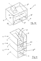
- a device for self-service removal of bakery products B '" is shown, wherein this second embodiment of the device has a substantially closed storage container 2.
- the baked goods B can reach a front-side removal region This also ensures that the baked goods B which can be selected by the customer near a viewing wall 5 are conveyed as respective individual parts by means of an auxiliary device 6 (FIG. Fig. 17 ) can be removed from the reservoir 2.
- the reservoir 2 is provided in the region of its stationary front, in particular consisting of transparent material viewing wall 5 with at least one return lock 7 forming discharge lock 8 '.
- this discharge lock 8 ' the individually moved bakery products B "' from the inner space 3 can be discharged in a particularly simple manner by the fact that a space in the storage container 2 laterally arranged insertion space 9 is specified for the customer.
- the reservoir 2 which has a substantially U-shaped cross-sectional contour, is provided with a two-part supporting floor 4 'in the region of its closing wall 12' extending between two parallel side walls 31, 32.
- these parts of the support base 4 formed as the front-side collecting plate 33 and the rear sieve plate 34 are kept removable from the inner space 3.
- the screen plate 34 (FIG. Fig. 17 ) one the insertion space 9 ( Fig. 16 ) in the region of the viewing wall 5 and the removal area E forming free zone F has.
- the return lock (general designated 7, is installed, the return lock 7 being designed as a cover unit 35 accommodating the insertion plate 24 accommodating the area of the collection plate 33 that can be raised from the area of the collection plate 33 Fig. 16 It is clear that extends below the insertion opening 24, a portion 36 of the two-part collection plate 33.
- This multi-part concept in the interior 3 of the storage container 2 provides that it is provided with at least one cleaning zone Z at least in the region below the two-part collecting plate 33 (plate parts 36 and 36 ').
- This cleaning zone Z receiving the crumb structures can be provided with respective collecting troughs 38.
- respective - provided with a cover part also not shown - cleaning openings are provided so that a permanent dissipation of crumb structures after opening the lid is possible.
- the construction of the collecting plate 33 provides that it rests against the lower end of the sieve plate 34 in such a way that a secure installation position is ensured.
- the collection plate 33 can still be fixed on respective support elements 41 on the horizontal region of the closing wall 12 '.
- the substantially U-shaped reservoir 2 with all internal parts forms a largely completely removable for cleaning modular system.
- This system can as a unit or at least in the form of respective individual parts - for example, part 35 - in an in Fig. 19 shown functional unit in the form of a presentation wall W 'are integrated.
- the devices 1 or parts thereof can define the removal areas 40, 40 ', 40 "that are accessible to the customer, so that a customer-specific" baked goods wall "can be used.
Landscapes
- Vending Machines For Individual Products (AREA)
Applications Claiming Priority (2)
| Application Number | Priority Date | Filing Date | Title |
|---|---|---|---|
| DE201220012003 DE202012012003U1 (de) | 2012-12-14 | 2012-12-14 | Vorrichtung zur Selbstbedienungsentnahme von Backwaren |
| DE201320007948 DE202013007948U1 (de) | 2013-09-05 | 2013-09-05 | Vorrichtung zur Selbstbedienungsentnahme von Backwaren |
Publications (1)
| Publication Number | Publication Date |
|---|---|
| EP2742829A1 true EP2742829A1 (fr) | 2014-06-18 |
Family
ID=49911078
Family Applications (1)
| Application Number | Title | Priority Date | Filing Date |
|---|---|---|---|
| EP13005788.8A Withdrawn EP2742829A1 (fr) | 2012-12-14 | 2013-12-12 | Dispositif de prélèvement en libre-service de produits de boulangerie |
Country Status (1)
| Country | Link |
|---|---|
| EP (1) | EP2742829A1 (fr) |
Citations (5)
| Publication number | Priority date | Publication date | Assignee | Title |
|---|---|---|---|---|
| DE202005009376U1 (de) * | 2005-06-14 | 2005-09-15 | Aldi Einkauf Gmbh & Co Ohg | Ausgabeeinheit für insbesondere Brötchen |
| EP1669009A1 (fr) * | 2004-12-09 | 2006-06-14 | Hertel, Günther | Dispositif de distribution |
| DE202005008141U1 (de) | 2005-05-24 | 2006-10-05 | Heinrich J. Kesseböhmer KG | Warenbehälter zur Selbstbedienunsentnahme |
| DE202007006139U1 (de) * | 2007-04-28 | 2008-09-11 | Heinrich J. Kesseböhmer KG | Warenbehälter zur Selbstbedienungsentnahme |
| DE202011104060U1 (de) * | 2011-08-04 | 2012-11-07 | Kesseböhmer Holding OHG | Ausgabevorrichtung für Brot, Brötchen o. dgl.unverpackte Waren |
-
2013
- 2013-12-12 EP EP13005788.8A patent/EP2742829A1/fr not_active Withdrawn
Patent Citations (5)
| Publication number | Priority date | Publication date | Assignee | Title |
|---|---|---|---|---|
| EP1669009A1 (fr) * | 2004-12-09 | 2006-06-14 | Hertel, Günther | Dispositif de distribution |
| DE202005008141U1 (de) | 2005-05-24 | 2006-10-05 | Heinrich J. Kesseböhmer KG | Warenbehälter zur Selbstbedienunsentnahme |
| DE202005009376U1 (de) * | 2005-06-14 | 2005-09-15 | Aldi Einkauf Gmbh & Co Ohg | Ausgabeeinheit für insbesondere Brötchen |
| DE202007006139U1 (de) * | 2007-04-28 | 2008-09-11 | Heinrich J. Kesseböhmer KG | Warenbehälter zur Selbstbedienungsentnahme |
| DE202011104060U1 (de) * | 2011-08-04 | 2012-11-07 | Kesseböhmer Holding OHG | Ausgabevorrichtung für Brot, Brötchen o. dgl.unverpackte Waren |
Similar Documents
| Publication | Publication Date | Title |
|---|---|---|
| DE102008062761B3 (de) | Besteckschublade für eine Geschirrspülmaschine | |
| EP1985209B1 (fr) | Récipient de marchandises pour le retrait en libre service | |
| DE202009006755U1 (de) | Warenausgabeeinheit zur Selbstbedienungsentnahme von Backwaren | |
| DE202005008141U1 (de) | Warenbehälter zur Selbstbedienunsentnahme | |
| EP1086616A2 (fr) | Paquet de semence pour semoir | |
| EP2554078A1 (fr) | Dispositif de distribution pour pain, petits pains ronds ou marchandises semblables non emballées | |
| DE202008001290U1 (de) | Ausgabevorrichtung für Brot, Brötchen o.dgl. unverpackte Lebensmittel | |
| WO2014118202A1 (fr) | Étagère de distribution | |
| DE4309915C2 (de) | Spülgutträger für Geschirrspülmaschinen | |
| EP2873352B1 (fr) | Unité de distribution de produits de boulangerie en libre-service | |
| DE202012012003U1 (de) | Vorrichtung zur Selbstbedienungsentnahme von Backwaren | |
| DE3639723C2 (fr) | ||
| EP2266442B1 (fr) | Dispositif d'extraction pour produits alimentaires | |
| EP2907951B1 (fr) | Étagère réfrigérante commerciale | |
| EP2580996A1 (fr) | Dispositif de distribution pour pain, petits pains, ou produits similaires non emballés | |
| EP2742829A1 (fr) | Dispositif de prélèvement en libre-service de produits de boulangerie | |
| DE202007006950U1 (de) | Warenbehälter zur Selbstbedienungsentnahme | |
| EP2907381B1 (fr) | Installation pour poules pondeuses | |
| EP4085816B1 (fr) | Dispositif de protection contre les projections, dispositif de réception d'articles à laver et lave-vaisselle domestique | |
| DE102008010421B4 (de) | Ausgabevorrichtung zur Selbstbedienungsentnahme von Brötchen o. dgl. Backwaren | |
| DE202013007948U1 (de) | Vorrichtung zur Selbstbedienungsentnahme von Backwaren | |
| DE102011008766B4 (de) | Selbstbedienungsvorrichtung für Warenpackungen | |
| EP3184003A2 (fr) | Dispositif de présentation et de vente | |
| EP3369671B1 (fr) | Conteneur de ventes et de transport destiné à la présentation de marchandises | |
| DE202007016569U1 (de) | Verkaufsgestell zum Präsentieren von Waren |
Legal Events
| Date | Code | Title | Description |
|---|---|---|---|
| PUAI | Public reference made under article 153(3) epc to a published international application that has entered the european phase |
Free format text: ORIGINAL CODE: 0009012 |
|
| 17P | Request for examination filed |
Effective date: 20131212 |
|
| AK | Designated contracting states |
Kind code of ref document: A1 Designated state(s): AL AT BE BG CH CY CZ DE DK EE ES FI FR GB GR HR HU IE IS IT LI LT LU LV MC MK MT NL NO PL PT RO RS SE SI SK SM TR |
|
| AX | Request for extension of the european patent |
Extension state: BA ME |
|
| R17P | Request for examination filed (corrected) |
Effective date: 20141204 |
|
| RBV | Designated contracting states (corrected) |
Designated state(s): AL AT BE BG CH CY CZ DE DK EE ES FI FR GB GR HR HU IE IS IT LI LT LU LV MC MK MT NL NO PL PT RO RS SE SI SK SM TR |
|
| STAA | Information on the status of an ep patent application or granted ep patent |
Free format text: STATUS: THE APPLICATION IS DEEMED TO BE WITHDRAWN |
|
| 18D | Application deemed to be withdrawn |
Effective date: 20160701 |