EP2741975B1 - Transport container - Google Patents
Transport container Download PDFInfo
- Publication number
- EP2741975B1 EP2741975B1 EP12758734.3A EP12758734A EP2741975B1 EP 2741975 B1 EP2741975 B1 EP 2741975B1 EP 12758734 A EP12758734 A EP 12758734A EP 2741975 B1 EP2741975 B1 EP 2741975B1
- Authority
- EP
- European Patent Office
- Prior art keywords
- wall
- frame structure
- transport container
- control element
- closed position
- Prior art date
- Legal status (The legal status is an assumption and is not a legal conclusion. Google has not performed a legal analysis and makes no representation as to the accuracy of the status listed.)
- Not-in-force
Links
Images


Classifications
-
- B—PERFORMING OPERATIONS; TRANSPORTING
- B65—CONVEYING; PACKING; STORING; HANDLING THIN OR FILAMENTARY MATERIAL
- B65D—CONTAINERS FOR STORAGE OR TRANSPORT OF ARTICLES OR MATERIALS, e.g. BAGS, BARRELS, BOTTLES, BOXES, CANS, CARTONS, CRATES, DRUMS, JARS, TANKS, HOPPERS, FORWARDING CONTAINERS; ACCESSORIES, CLOSURES, OR FITTINGS THEREFOR; PACKAGING ELEMENTS; PACKAGES
- B65D88/00—Large containers
- B65D88/02—Large containers rigid
- B65D88/12—Large containers rigid specially adapted for transport
- B65D88/127—Large containers rigid specially adapted for transport open-sided container, i.e. having substantially the whole side free to provide access, with or without closures
-
- B—PERFORMING OPERATIONS; TRANSPORTING
- B65—CONVEYING; PACKING; STORING; HANDLING THIN OR FILAMENTARY MATERIAL
- B65D—CONTAINERS FOR STORAGE OR TRANSPORT OF ARTICLES OR MATERIALS, e.g. BAGS, BARRELS, BOTTLES, BOXES, CANS, CARTONS, CRATES, DRUMS, JARS, TANKS, HOPPERS, FORWARDING CONTAINERS; ACCESSORIES, CLOSURES, OR FITTINGS THEREFOR; PACKAGING ELEMENTS; PACKAGES
- B65D90/00—Component parts, details or accessories for large containers
- B65D90/008—Doors for containers, e.g. ISO-containers
Definitions
- the invention relates to a transport container, in particular vehicle body or container, according to the preamble of claim 1.
- a transport container with a arranged in the roof area device for transferring a side wall between a closed position and an open position known to gain access to the cargo space of the transport container in the open position of the pivoted side wall.
- the wall is connected to a pivotally mounted handlebar, which is pivotable by means of a hydraulically actuated linear drive.
- a further linear drive is provided to move the side wall before the introduction of the pivoting operation away from the transport container.
- the additional linear drive for moving the side wall ensures that any seals on the contact surfaces are not damaged.
- the transport container can be used as a refrigerated transporter.
- the linear drive for pivoting the side wall is connected via a deflection means with a shaft which is coupled to the linear drive for displacing the side wall.
- DE 10 2006 053 523 B3 relates to a transport container in which a side wall is moved by means of a hydraulic drive between closed and open position.
- the side wall is guided over rollers on the upper edge of the transport container.
- WO 03/045822 A1 discloses a different type of container, the lid of which by means of a spring-loaded hinge mechanism after is pivotable above.
- the lid is attached to the container via a fixed pivot point.
- the object of the present invention is now to provide a transport container of the type mentioned, with which a structurally simple drive unit to achieve a sealed transport space is created in the closed position.
- the pivoting device has a rocker arm connected in each case in an articulated manner to the steering element and the wall, which is adapted to pivot the steering element out of the closed position of the wall at least in the area of a contact surface between the wall and the frame structure to translate a displacement of the wall from the closed position transversely to the plane of extension of the wall in an intermediate position spaced from the frame structure, from which the wall can be moved into the open position.
- the drive unit is accordingly actuated, which is coupled to the pivotally mounted steering element in order to pivot the steering element out of its transport position corresponding to the closed position of the wall.
- the pivotal movement of the steering element from the closed position of the wall is transmitted to the pivotally mounted between the steering element and the wall rocker arm, which moves the wall from the closed position to the intermediate frame position removed from the frame structure.
- the wall of the closed position adjacent the frame structure is displaced outwards in a translational movement, before the pivoting of the wall is initiated via the drive unit.
- the displacement of the wall between the closed position and the intermediate position takes place substantially perpendicular to the plane of extension of the wall or substantially perpendicular to the contact surface between the frame structure and the wall.
- the frame structure has a receptacle, in particular in the form of a channel-shaped or L-shaped receiving strip or a receiving nose, which is set up to lock a longitudinal edge of the wall opposite the wall of the drive unit, in particular on the bottom side.
- a receptacle in particular in the form of a channel-shaped or L-shaped receiving strip or a receiving nose, which is set up to lock a longitudinal edge of the wall opposite the wall of the drive unit, in particular on the bottom side.
- the longitudinal edge of the wall is arranged in the receiving strip, whereby the wall is in a suitable locking position for transport.
- the wall is tilted relative to the closed position until the arranged in the receiving bar longitudinal edge of the wall, preferably upon reaching the intermediate position of the wall, slides out of the receiving bar.
- the wall between the closed and intermediate position on the associated rocker arm is approximately perpendicular to the main extension of the wall slidably, wherein the linear displacement of the wall is superimposed by the drive unit, a tilting movement of the wall to slide out the side edge of the receiving bar.
- the contact surfaces between the wall and the frame structure are arranged at a distance from each other; the drive unit is also adapted to cause pivoting of the wall in the direction of the open position upon reaching the intermediate position.
- at least one seal can be arranged, which can be fastened to the inner surface of the wall or to a contact surface of the frame structure.
- the seal of the transport container can be permanently protected.
- the wall is first pivoted from the open position to the intermediate position. Subsequently, the wall is used by means of the rocker arm from the intermediate position in the close to the frame structure fitting closed position.
- the drive unit opposite side edge of the wall can be arranged in the receiving strip of the frame structure, whereby the wall is locked upon reaching the closed position.
- a blocking means of the wall when retracted into the closed position with arranged on the frame structure rollers on which the wall rolls during the opening and closing process is positively engaged.
- the embodiment according to the invention thus permanently ensures the sealing of the transport container, so that the transport container can preferably be designed as a refrigerated transporter with a cooling device.
- the above-described displacement of the wall away from the frame structure to the outside in the intermediate position is accomplished according to the invention via the rocker arm between the wall and the steering element.
- the rocker arm couples the pivoting movement of the steering element between the closed and the intermediate position of the wall at least in the region of the contact surface of the transport container with a substantially translational movement of the wall in a direction transverse to the plane of extension of the wall.
- the arrangement of the rocker arm between the steering element and the wall thus allows in a structurally simple, reliable way to perform the opening operation in at least two phases, the wall is first offset to the outside, in particular away from the seals on the contact surfaces, in the intermediate position and the Wall is pivoted after reaching the intermediate position in the direction of the open position.
- the drive unit can advantageously be substantially simplified; This can also reduce the cost of the transport container.
- the longitudinal axis of the rocker arm in the closed position of the wall substantially is arranged parallel to the longitudinal axis of the steering element, preferably in the same horizontal plane.
- the longitudinal axis of the rocker arm during pivoting of the steering element from the closed position of the wall relative to the longitudinal axis of the steering element is pivotable such that the pivot axis between the rocker arm and the wall is preferably displaceable in a substantially horizontal direction until it reaches the intermediate position of the wall which is at a distance from the frame structure. Accordingly, the free end portion of the rocker arm is pivoted in the transfer of the steering element in the intermediate position of the wall relative to the steering element.
- the movement of the coupled with the wall end portion of the rocker arm in this case causes the displacement of the wall to the outside in the intermediate position.
- the rocker arm is articulated to an upper end portion of the wall, which is arranged in the closed position of the wall adjacent to the roof portion of the frame structure.
- the rocker arm is arranged in the intermediate position of the wall at an angle of less than 90 ° to the roof region of the frame structure such that the rocker arm can be folded during the closing operation by the pivoting of the steering element in the direction of the closed position; This reliably prevents the pivoting movement of the rocker arm or the steering element is locked from the intermediate position, as would be the case with a vertical power transmission.
- the rocker arm is arranged closer to the free end region of the steering element than at the opposite end pivotably mounted on the frame structure. This will be an advantageous Transmission ratio between the pivoting of the steering element.
- the rocker arm has a smaller longitudinal extent than the steering element, which is preferably designed as an elongated handlebar the wall and the pivoting of the rocker arm until reaching the intermediate position.
- the free end portion of the steering element in a hingedly connected to the wall guide element, in particular a link, is slidably mounted.
- the guide element in the manner of a link is preferably articulated in an upper, lateral edge region of the wall.
- the guide element has a stop which limits the displacement of the steering element in the guide element until reaching a stop position, preferably corresponding to the intermediate position of the wall, wherein the displaced into the stop position steering element, the wall on the guide element in the direction of Open position takes along.
- the free end region of the steering element is therefore freely displaceable between the closed position and the intermediate position of the wall in the guide element.
- the drive unit has a, in particular a single, linear drive for pivoting the steering element of the closed position of the wall on the spaced apart from the frame structure intermediate position of the wall in the open position of the wall.
- a single linear drive of the drive unit can be adapted to move the wall by pivoting the hinged thereto steering member via the rocker arm from the closed position into the spaced apart from the frame structure intermediate position and upon reaching the Intermediate position to cause a pivoting of the wall in the open position.
- the entire opening process is preferably carried out here with a single piston stroke of the linear drive.
- the linear drive is designed as a preferably hydraulically, pneumatically or electrically operable cylinder-piston drive with a cylinder and a cylinder slidably mounted relative to the cylinder.
- the longitudinal axis of the preferably arranged in the roof region of the frame structure linear drive in the closed position of the wall is arranged substantially parallel to the longitudinal axis of the steering element, in particular in the same horizontal plane, a particularly compact arrangement can be achieved, which at a given total height of the transport container comparatively small space having.
- the steering element in the closed position of the wall is arranged substantially horizontally in the roof region of the frame structure and pivoted in the transfer to the open position by more than 90 °.
- the wall is arranged in its open position substantially above the roof area of the frame structure.
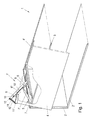
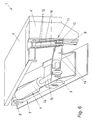
- a transport container 1 is shown, which is designed in particular as a vehicle body for a truck.
- the transport container 1 has a frame structure 2 which is only schematically illustrated in the drawings, in particular, forms a roof area 3.
- the frame structure 2 of the transport container includes a transport space bounded on all sides by walls connected to the frame structure 2.
- a wall 4 is pivoted by means of at least one pivoting device 1 'from a closed position lying on the frame structure 2 in a substantially above the roof area 3 arranged open position in which a loading opening to the transport space of the transport container 1 is released.
- the transport container 1 expediently has a second, identically designed pivoting device 1 ', which is arranged at the opposite end of the roof area 3 (not shown).
- a one-piece side wall is provided in the embodiment shown, the in Fig. 1 is shown approximately halfway between its closed and its open position.
- a wall composed of several, in particular pivotally interconnected, wall elements would also be conceivable.
- a steering element 6 is provided, which is mounted pivotably about a pivot axis 6 'on the frame structure 2.
- the steering element is formed by an elongated, nostinunver Slichen handlebar. The steering element 6 is connected to a drive unit 5, with which the wall 4 from the closed to the open position can be transferred.
- the drive unit 5 has a particularly hydraulically actuated linear drive 7 with a displaceable in a cylinder 7 a piston 7 b, which engages at a pivot axis 8 adjacent to the frame structure 2 pivotally mounted end portion of the steering member 6 thereto.
- the pivot axis 8 is formed by a shaft element arranged transversely to the longitudinal axis 6 '' of the steering element 12.
- the linear drive 7 is furthermore attached to the frame structure 2 so as to be articulated via a pivot axis 8 '.
- Fig. 1 the suspension of the wall 4 on the steering element 6 in the embodiment shown on the one hand via a rocker arm 9 which is mounted in each case about a pivot axis 10 and 10 'pivotally mounted on the steering element 6 and on the wall 4.
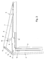
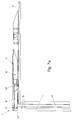
- the rocker arm 9 is in this case hinged to a transverse to the main extension of the wall 4 extending roof section 4 ', which in the closed position of the wall 4 rests substantially horizontally on the roof area 3 of the frame structure 2 (see. Fig. 2 ).
- the opposite end of the rocker arm 9, which has a shorter longitudinal extent with respect to the steering element 6, is articulated thereto adjacent to the free end region of the steering element 6.
- the upper edge region of the wall 4 is further connected via a guide member 11 with the free end portion of the steering element 6.
- the guide element 11 is formed as a backdrop with an elongated guide opening 12, in which a matching pin 13 of the free end portion of the steering element 6 is slidably mounted.
- the guide member 11 is pivotally mounted about a pivot axis 11 'in the upper corner region of the wall 4.
- the wall 4 is in its closed position via corresponding contact surfaces on the frame structure 2.
- the contact surfaces have, in particular in the upper end region of the wall 4, seals 16 (see. Fig. 7 ) to provide in the closed position of the wall 4 a sealed transport space, which allows use of the transport container 1 as a refrigerated transporter.
- the longitudinal axis 7 'of the arranged in the roof area of the frame structure 2 linear drive 7 is arranged in the closed position of the wall 4 substantially parallel to the longitudinal axis 6''of the steering element 6 and in the same horizontal plane.
- the steering element 6 is in the closed position of the wall 4 in a substantially horizontal position in the roof area 3 of the frame structure 3 before.
- the closed position of the wall 4 corresponds to a transportation or transport operation provided transport position, in which the drive unit 5 is lowered to save space in the roof area 3 of the transport container 1.
- the wall 4 is arranged to initiate the opening operation by means of the drive unit 5 in a substantially parallel to the closed position of the wall 4 outwardly offset intermediate position.
- the linear actuator 7 is actuated, which the steering element 6 from the in Fig. 2 shown horizontal position corresponding to the closed position the wall 4 is pivoted upwards.
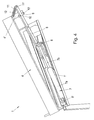
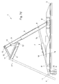
- This pivoting of the steering element 6 is implemented by means of the rocker arm 9 at least in the upper end region of the wall 4 in a displacement of the wall 4 from the closed position into a spaced apart from the frame structure intermediate position, which in Fig. 3 is shown.
- the translational movement of the wall 4 away from the frame structure 2 in the intermediate position is substantially perpendicular to the plane of extension of the wall 4, ie substantially perpendicular to the contact surfaces in the upper end region of the wall 4, around the attached to the contact surfaces seals 16 (see. Fig. 7 ), which could be damaged in a direct pivoting from the closed position of the wall 4.
- the wall 4 is also tilted in the transfer to the intermediate position relative to the closed position by one of the drive unit 5 opposite, bottom side longitudinal edge of the wall 4 in a receiving bar 2 '(see. Fig. 1 ) is arranged on the frame structure 2, which serves to lock the wall 4 in the closed position.
- the bottom side edge of the wall 4 slides out of the receiving strip 2 'when the wall 4 is pivoted in the direction of the open position.
- the longitudinal axis 9 'of the rocker arm 9, which is arranged in the closed position of the wall 4 substantially parallel to the longitudinal axis 6 "of the steering element 6 and in the same horizontal plane is at the pivoting of the steering element 6 from the closed position of the wall 4 relative to the longitudinal axis. 6 "of the steering element 6 pivoted.
- the pivot axis 10 'between the rocker arm 9 and the wall 4 is displaced in a substantially horizontal direction outwards until the wall 4 reaches the intermediate position spaced from the frame structure 2.
- the free end portion of the steering element 6 is displaced in the guide opening 12 of the guide member 11 in a stop position, which is defined in the embodiment shown by a narrow-side end of the guide hole 12.
- the wall 4 is made of the in Fig. 3 shown Intermediate position, in which the wall 4 was spaced to protect the seals 16 at the contact surfaces of the frame structure 2, in a substantially above the roof portion 3 of the frame structure 2 arranged open position transferred, which in Fig. 4 is shown.
- the piston 7b of the linear drive 7 of the drive unit 5 is further extended after reaching the intermediate position of the wall 4, whereby the steering element 6 is pivoted in the direction of the open position.
- the free end region of the steering element 6, which is present in the guide element 12 in the stop position takes in this case the upper end region of the wall 4 via the guide element 12 in the direction of the open position.
- the steering element 6 is pivoted in the transfer to the open position by more than 90 °.
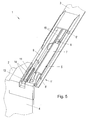
- Fig. 5 to 7 is a further embodiment of the transport container 1 is shown.
- the guide member 11 is articulated in a U-shaped receptacle in the upper corner of the wall 4.
- the guide element 11 here has two further scenes 14, which store the pin 13 of the free end portion of the steering element 6 on both sides.
- the steering element 6 is composed of individual hollow sections 15, which are characterized by high stiffness values at low weight.
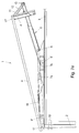
- the transfer of the wall 4 of the transport container 1 according to the Fig. 5 . 6 is from the Fig. 7a to 7b visible, which each show a view of the transport container 1.
- the wall 4 is in the closed position (see. Fig. 2 ) at least in the upper end or corner region of the wall 4 via corresponding contact surfaces on the frame structure 2.
- the seals 16 (for example in the form of O-rings) can be seen, which are attached to the contact surfaces of the frame structure 2.
- the seals 16 may alternatively be attached to the inner surface of the wall 4.
- the longitudinal axis 6 "of the steering element 6, the longitudinal axis 7 'of the linear drive 7, the longitudinal axis 9' of the rocker arm 9 and the longitudinal axis 11 '' of the guide element 11 arranged substantially parallel to each other and in the same horizontal plane.
- rollers 17 which for supporting the wall 4 during the pivoting movement (see. Fig. 7d . 7e ) serves.
- the rollers 17 are at least partly received in corresponding locking means 17 ", so that the wall 4 is advantageously secured in the closed position against up and down movements, the bottom side edge of the wall 4 being in the corresponding receiving bar 2 'of the frame structure 2 secured.
- Fig. 7b the wall 4 is displaced by actuation of the linear drive 7 in a substantially horizontal direction transversely to the main extension of the wall 4 (see arrow 17 ') in the direction of the frame assembly 2 spaced intermediate position by the pivoting of the steering element 6 via the rocker arm 9 in the displacement of the pivot axis 10 'between the wall 4 and the rocker arm 9 is implemented.
- the free end region of the steering element 6 is thereby displaced in the guide element 12.
- the wall 4 is displaced away from the seals 16 until it reaches the intermediate structure spaced from the frame structure 2.
- the wall 4 is spaced from the seals 16 before the pivoting of the wall 4 is started.
- the longitudinal axis 9 'of the rocker arm 9 is arranged at an angle of inclination ⁇ of preferably approximately 60 ° to the longitudinal axis 6 "of the steering element 6, the angle of inclination ⁇ is also less than 90 ° relative to the roof area 3 of the frame structure 2,
- the wall 4 can be used during closing by folding the rocker arm 9 via the steering element 6 in the closed position adjacent to the frame structure 2.
- the longitudinal axis 6 "of the steering element 6 is in the intermediate position relative to the horizontal closed position ( Fig. 7a ) according to the tilted arrangement the rocker arm 9 is pivoted.
- the articulation of the rocker arm 9 adjacent to the free end region of the steering element 6 in this case allows a suitable translation of the pivoting movement of the steering element 6 in the pivoting of the rocker arm 9.
- Fig. 7c Furthermore, it can be seen, the free end portion of the steering element 6 is displaced in the intermediate position of the wall 4 in the stop position of the guide member 11.
- the longitudinal axis 11 "of the guide member 11 is pivoted in the intermediate position relative to the horizontal position accordingly.
- the further piston stroke of the linear actuator 7 causes a pivoting of the wall 4 of the intermediate position in the direction of the open position.
- the wall 4 is pulled by the steering element 6 via the guide member 12 upwards. From a certain pivot angle of the steering element 6, the inner surface of the wall 4 rests on the rollers 17, but without coming into contact with the seals 16 at the contact surfaces of the transport container 3 in contact.
- FIG. 7e how out Fig. 7e can be seen, the wall 4 is then pivoted to the loading opening fully releasing open position, in which the wall 4 is disposed above the roof portion 3 of the frame structure 2.
- the figures further illustrate schematically hydraulic lines 18 which may be coupled to an electronic control device (not shown).
Description
Die Erfindung betrifft einen Transportbehälter, insbesondere Fahrzeugaufbau oder Container, gemäß dem Oberbegriff von Anspruch 1.The invention relates to a transport container, in particular vehicle body or container, according to the preamble of
Aus der
Darüber hinaus sind im Stand der Technik andersartige Transportbehälter bekannt, bei welchen eine horizontale Verschiebung in eine Zwischenposition vor Einleitung des Verschwenkvorgangs nicht vorgesehen ist.In addition, other types of transport containers are known in the prior art, in which a horizontal displacement is not provided in an intermediate position prior to the initiation of the pivoting operation.
Darüber hinaus sind im Stand der Technik, vgl.
In der
Die Aufgabe der vorliegenden Erfindung besteht nun darin, einen Transportbehälter der eingangs angeführten Art zu schaffen, mit welchem eine konstruktiv einfache Antriebseinheit zur Erzielung eines abgedichteten Transportraums in der Schließstellung geschaffen wird.The object of the present invention is now to provide a transport container of the type mentioned, with which a structurally simple drive unit to achieve a sealed transport space is created in the closed position.
Diese Aufgabe wird durch einen Transportbehälter mit den Merkmalen von Anspruch 1 gelöst.This object is achieved by a transport container having the features of
Erfindungsgemäß weist die Verschwenkvorrichtung einen jeweils gelenkig mit dem Lenkelement und der Wand verbundenen Kipphebel auf, welcher dazu eingerichtet ist, eine Verschwenkung des Lenkelements aus der Schließstellung der Wand zumindest im Bereich einer Kontaktfläche zwischen der Wand und dem Rahmenaufbau in eine Verschiebung der Wand von der Schließstellung quer zur Erstreckungsebene der Wand in eine vom Rahmenaufbau beabstandete Zwischenstellung umzusetzen, aus der die Wand in die Offenstellung überführbar ist.According to the invention, the pivoting device has a rocker arm connected in each case in an articulated manner to the steering element and the wall, which is adapted to pivot the steering element out of the closed position of the wall at least in the area of a contact surface between the wall and the frame structure to translate a displacement of the wall from the closed position transversely to the plane of extension of the wall in an intermediate position spaced from the frame structure, from which the wall can be moved into the open position.
Zur Einleitung des Öffnungsvorgangs wird demnach die Antriebseinheit betätigt, welche mit dem schwenkbar gelagerten Lenkelement gekoppelt ist, um das Lenkelement aus seiner der Schließstellung der Wand entsprechenden Transportposition zu verschwenken. Die Schwenkbewegung des Lenkelements aus der Schließstellung der Wand wird auf den gelenkig zwischen dem Lenkelement und der Wand gelagerten Kipphebel übertragen, welcher die Wand aus der Schließstellung in die vom Rahmenaufbau entfernte Zwischenstellung verschiebt. Demnach wird die Wand von der am Rahmenaufbau anliegenden Schließstellung in einer translatorischen Bewegung nach außen versetzt, bevor die Verschwenkung der Wand über die Antriebseinheit eingeleitet wird. Die Verschiebung der Wand zwischen der Schließstellung und der Zwischenstellung erfolgt dabei im Wesentlichen senkrecht zur Erstreckungsebene der Wand bzw. im Wesentlichen senkrecht zu der Kontaktfläche zwischen dem Rahmenaufbau und der Wand. Gemäß einer bevorzugten Ausführung weist der Rahmenaufbau eine Aufnahme, insbesondere in Form einer rinnen- bzw. L-förmigen Aufnahmeleiste bzw. einer Aufnahmenase, auf, welche zur Verriegelung einer der Aufhängung der Wand an der Antriebseinheit gegenüberliegenden, insbesondere bodenseitigen Längskante der Wand eingerichtet ist. In der Schließstellung der Wand ist die Längskante der Wand in der Aufnahmeleiste angeordnet, wodurch die Wand in einer für den Transport geeigneten Verriegelungsstellung vorliegt. Beim Verschieben der Wand aus der Schließstellung mittels der erfindungsgemäßen Antriebseinheit wird die Wand gegenüber der Schließstellung gekippt, bis die in der Aufnahmeleiste angeordnete Längskante der Wand, vorzugsweise bei Erreichen der Zwischenstellung der Wand, aus der Aufnahmeleiste herausgleitet. Somit ist die Wand zwischen Schließ- und Zwischenstellung über den damit verbundenen Kipphebel annähernd senkrecht zur Haupterstreckung der Wand verschiebbar, wobei der Linearverschiebung der Wand durch die Antriebseinheit eine Kippbewegung der Wand bis zum Herausgleiten der Seitenkante aus der Aufnahmeleiste überlagert ist. In der Zwischenstellung der Wand sind die Kontaktflächen zwischen der Wand und dem Rahmenaufbau in einem Abstand zueinander angeordnet; die Antriebseinheit ist darüber hinaus dazu eingerichtet, bei Erreichen der Zwischenstellung eine Verschwenkung der Wand in Richtung der Offenstellung zu bewirken. Im Bereich der Kontaktfläche zwischen der Wand und dem Rahmenaufbau kann zumindest eine Dichtung angeordnet sein, welche an der Innenfläche der Wand oder an einer Anlagefläche des Rahmenaufbaus befestigt sein kann. Indem die Wand aus der abgedichteten Schließstellung zunächst translatorisch nach außen in die Zwischenstellung bewegt wird, bevor die Verschwenkbewegung der Wand eingeleitet wird, kann die Dichtung des Transportbehälters dauerhaft geschont werden. Hierdurch werden bei herkömmlichen Transportbehältern mit direkter Verschwenkung der Wand aus der Schließstellung häufig auftretende Schäden an den Dichtungen zuverlässig vermieden, welche durch Scherbelastungen bei Einleitung der Verschwenkbewegung hervorgerufen werden. Beim Schließvorgang wird die Wand zunächst aus der Offenstellung in die Zwischenstellung verschwenkt. Anschließend wird die Wand mittels des Kipphebels aus der Zwischenstellung in die dicht am Rahmenaufbau anliegende Schließstellung herangezogen. Hierbei kann die der Antriebseinheit gegenüberliegende Seitenkante der Wand in der Aufnahmeleiste des Rahmenaufbaus angeordnet werden, wodurch die Wand bei Erreichen der Schließstellung verriegelt wird. Zudem ist es hierbei weiters von Vorteil, wenn ein Sperrmittel der Wand beim Einfahren in die Schließstellung mit am Rahmenaufbau angeordneten Rollen, auf welchen die Wand beim Öffnungs- bzw. Schließvorgang abrollt, formschlüssig in Eingriff gebracht wird. Die erfindungsgemäße Ausführung gewährleistet somit dauerhaft die Abdichtung des Transportbehälters, so dass der Transportbehälter bevorzugt als Kühltransporter mit einer Kühlvorrichtung ausgebildet sein kann. Die zuvor beschriebene Verschiebung der Wand weg vom Rahmenaufbau nach außen in die Zwischenstellung wird erfindungsgemäß über den Kipphebel zwischen der Wand und dem Lenkelement bewerkstelligt. Der Kipphebel koppelt die Verschwenkbewegung des Lenkelements zwischen der Schließ- und der Zwischenstellung der Wand zumindest im Bereich der Kontaktfläche des Transportbehälters mit einer im Wesentlichen translatorischen Bewegung der Wand in eine Richtung quer zur Erstreckungsebene der Wand. Die Anordnung des Kipphebels zwischen dem Lenkelement und der Wand ermöglicht demnach auf konstruktiv einfache, zuverlässige Weise, den Öffnungsvorgang in zumindest zwei Phasen durchzuführen, wobei die Wand zunächst nach außen, insbesondere weg von den Dichtungen an den Kontaktflächen, in die Zwischenstellung versetzt wird und die Wand nach Erreichen der Zwischenstellung in Richtung der Offenstellung verschwenkt wird. Indem die Versetzung der Wand in die Zwischenstellung vom Kipphebel, einem passiven Bauteil, bewerkstelligt wird, kann die Antriebseinheit vorteilhafterweise wesentlich vereinfacht werden; hierdurch können zudem die Kosten für den Transportbehälter gesenkt werden.To initiate the opening operation, the drive unit is accordingly actuated, which is coupled to the pivotally mounted steering element in order to pivot the steering element out of its transport position corresponding to the closed position of the wall. The pivotal movement of the steering element from the closed position of the wall is transmitted to the pivotally mounted between the steering element and the wall rocker arm, which moves the wall from the closed position to the intermediate frame position removed from the frame structure. Accordingly, the wall of the closed position adjacent the frame structure is displaced outwards in a translational movement, before the pivoting of the wall is initiated via the drive unit. The displacement of the wall between the closed position and the intermediate position takes place substantially perpendicular to the plane of extension of the wall or substantially perpendicular to the contact surface between the frame structure and the wall. According to a preferred embodiment, the frame structure has a receptacle, in particular in the form of a channel-shaped or L-shaped receiving strip or a receiving nose, which is set up to lock a longitudinal edge of the wall opposite the wall of the drive unit, in particular on the bottom side. In the closed position of the wall, the longitudinal edge of the wall is arranged in the receiving strip, whereby the wall is in a suitable locking position for transport. When moving the wall from the closed position by means of the drive unit according to the invention, the wall is tilted relative to the closed position until the arranged in the receiving bar longitudinal edge of the wall, preferably upon reaching the intermediate position of the wall, slides out of the receiving bar. Thus, the wall between the closed and intermediate position on the associated rocker arm is approximately perpendicular to the main extension of the wall slidably, wherein the linear displacement of the wall is superimposed by the drive unit, a tilting movement of the wall to slide out the side edge of the receiving bar. In the intermediate position of the wall, the contact surfaces between the wall and the frame structure are arranged at a distance from each other; the drive unit is also adapted to cause pivoting of the wall in the direction of the open position upon reaching the intermediate position. In the region of the contact surface between the wall and the frame structure, at least one seal can be arranged, which can be fastened to the inner surface of the wall or to a contact surface of the frame structure. By the wall from the sealed closed position is initially moved translationally outwardly into the intermediate position before the pivoting movement of the wall is initiated, the seal of the transport container can be permanently protected. As a result, in conventional transport containers with direct pivoting of the wall from the closed position often occurring damage to the seals reliably avoided, which are caused by shear loads at the initiation of the pivoting movement. During the closing process, the wall is first pivoted from the open position to the intermediate position. Subsequently, the wall is used by means of the rocker arm from the intermediate position in the close to the frame structure fitting closed position. Here, the drive unit opposite side edge of the wall can be arranged in the receiving strip of the frame structure, whereby the wall is locked upon reaching the closed position. Moreover, it is also advantageous if a blocking means of the wall when retracted into the closed position with arranged on the frame structure rollers on which the wall rolls during the opening and closing process, is positively engaged. The embodiment according to the invention thus permanently ensures the sealing of the transport container, so that the transport container can preferably be designed as a refrigerated transporter with a cooling device. The above-described displacement of the wall away from the frame structure to the outside in the intermediate position is accomplished according to the invention via the rocker arm between the wall and the steering element. The rocker arm couples the pivoting movement of the steering element between the closed and the intermediate position of the wall at least in the region of the contact surface of the transport container with a substantially translational movement of the wall in a direction transverse to the plane of extension of the wall. The arrangement of the rocker arm between the steering element and the wall thus allows in a structurally simple, reliable way to perform the opening operation in at least two phases, the wall is first offset to the outside, in particular away from the seals on the contact surfaces, in the intermediate position and the Wall is pivoted after reaching the intermediate position in the direction of the open position. By the displacement of the wall in the intermediate position of the rocker arm, a passive component, accomplished, the drive unit can advantageously be substantially simplified; This can also reduce the cost of the transport container.
Zur Erzielung einer platzsparenden Anordnung der Antriebseinheit in der Schließstellung der Wand ist es günstig, wenn die Längsachse des Kipphebels in der Schließstellung der Wand im Wesentlichen parallel zur Längsachse des Lenkelements, vorzugsweise in derselben horizontalen Ebene, angeordnet ist.To achieve a space-saving arrangement of the drive unit in the closed position of the wall, it is advantageous if the longitudinal axis of the rocker arm in the closed position of the wall substantially is arranged parallel to the longitudinal axis of the steering element, preferably in the same horizontal plane.
Zur Umsetzung der Verschwenkbewegung des Lenkelements in die Verschiebung der Wand weg vom Rahmenaufbau ist es von Vorteil, wenn die Längsachse des Kipphebels bei der Verschwenkung des Lenkelements aus der Schließstellung der Wand relativ zur Längsachse des Lenkelements derart verschwenkbar ist, dass die Schwenkachse zwischen dem Kipphebel und der Wand vorzugsweise in im Wesentlichen horizontaler Richtung bis zum Erreichen der vom Rahmenaufbau beabstandeten Zwischenstellung der Wand verschiebbar ist. Demnach wird der freie Endbereich des Kipphebels bei der Überführung des Lenkelements in die Zwischenstellung der Wand relativ zum Lenkelement verschwenkt. Die Bewegung des mit der Wand gekoppelten Endbereichs des Kipphebels bewirkt hierbei die Verschiebung der Wand nach außen in die Zwischenstellung.To implement the pivoting movement of the steering element in the displacement of the wall away from the frame structure, it is advantageous if the longitudinal axis of the rocker arm during pivoting of the steering element from the closed position of the wall relative to the longitudinal axis of the steering element is pivotable such that the pivot axis between the rocker arm and the wall is preferably displaceable in a substantially horizontal direction until it reaches the intermediate position of the wall which is at a distance from the frame structure. Accordingly, the free end portion of the rocker arm is pivoted in the transfer of the steering element in the intermediate position of the wall relative to the steering element. The movement of the coupled with the wall end portion of the rocker arm in this case causes the displacement of the wall to the outside in the intermediate position.
Gemäß einer bevorzugten Ausführung des Transportbehälters ist vorgesehen, dass der Kipphebel an einem oberen Endbereich der Wand angelenkt ist, welcher in der Schließstellung der Wand benachbart dem Dachbereich des Rahmenaufbaus angeordnet ist. Hierbei jeweils an gegenüberliegenden Seiten des oberen Endbereichs der Wand jeweils eine eigene, vorzugsweise ident ausgebildete Antriebseinheit vorhanden sein. Bevorzugt ist der Kipphebel in der Zwischenstellung der Wand in einem Winkel von weniger als 90° zum Dachbereich des Rahmenaufbaus derart angeordnet, dass der Kipphebel beim Schließvorgang durch die Verschwenkung des Lenkelements in Richtung der Schließstellung eingeklappt werden kann; hierdurch wird zuverlässig verhindert, dass die Verschwenkbewegung des Kipphebels bzw. des Lenkelements aus der Zwischenstellung gesperrt wird, wie dies bei einer senkrechten Kraftübertragung der Fall wäre.According to a preferred embodiment of the transport container is provided that the rocker arm is articulated to an upper end portion of the wall, which is arranged in the closed position of the wall adjacent to the roof portion of the frame structure. Here, in each case on separate sides of the upper end region of the wall each have their own, preferably identically designed drive unit be present. Preferably, the rocker arm is arranged in the intermediate position of the wall at an angle of less than 90 ° to the roof region of the frame structure such that the rocker arm can be folded during the closing operation by the pivoting of the steering element in the direction of the closed position; This reliably prevents the pivoting movement of the rocker arm or the steering element is locked from the intermediate position, as would be the case with a vertical power transmission.
Zur Verschiebung der Wand von der Schließstellung in die Zwischenstellung ist der Kipphebel benachbart dem freien Endbereich des Lenkelements an diesem angelenkt. Demnach ist der Kipphebel näher am freien Endbereich des Lenkelements als am gegenüberliegenden, am Rahmenaufbau schwenkbar gelagerten Ende angeordnet. Hierdurch wird ein vorteilhaftes Übersetzungsverhältnis zwischen der Verschwenkung des Lenkelements der Wand und der Verschwenkung des Kipphebels bis zum Erreichen der Zwischenstellung erzielt.Zudem ist es von Vorteil, wenn der Kipphebel eine geringere Längserstreckung als das Lenkelement aufweist, welches vorzugsweise als langgestreckter Lenker ausgeführt ist.To shift the wall from the closed position to the intermediate position of the rocker arm is adjacent to the free end portion of the steering element hinged thereto. Accordingly, the rocker arm is arranged closer to the free end region of the steering element than at the opposite end pivotably mounted on the frame structure. This will be an advantageous Transmission ratio between the pivoting of the steering element In addition, it is advantageous if the rocker arm has a smaller longitudinal extent than the steering element, which is preferably designed as an elongated handlebar the wall and the pivoting of the rocker arm until reaching the intermediate position.
Zur Führung des Lenkelements während des Öffnungsvorgangs der Wand ist es günstig, wenn der freie Endbereich des Lenkelements in einem gelenkig mit der Wand verbundenen Führungselement, insbesondere einer Kulisse, verschieblich gelagert ist. Das Führungselement in der Art einer Kulisse ist vorzugsweise in einem oberen, seitlichen Randbereich der Wand gelenkig gelagert.To guide the steering element during the opening process of the wall, it is advantageous if the free end portion of the steering element in a hingedly connected to the wall guide element, in particular a link, is slidably mounted. The guide element in the manner of a link is preferably articulated in an upper, lateral edge region of the wall.
Gemäß einer besonders bevorzugten Ausführung weist das Führungselement einen Anschlag auf, welcher die Verschiebung des Lenkelements in dem Führungselement bis zum Erreichen einer Anschlagposition, vorzugsweise entsprechend der Zwischenstellung der Wand, begrenzt, wobei das in die Anschlagposition verschobene Lenkelement die Wand über das Führungselement in Richtung der Offenstellung mitnimmt. Der freie Endbereich des Lenkelements ist demnach zwischen der Schließ- und der Zwischenstellung der Wand in dem Führungselement frei verschieblich. Sobald der freie Endbereich des Lenkelements beim Öffnungsvorgang die Anschlagposition des Führungselements erreicht hat, bewirkt eine weitere Verschwenkung des Lenkelements in Richtung der Offenstellung, dass die Wand über das Führungselement nach oben mitgenommen wird. Demnach kann durch die Anordnung des Führungselements die Verschwenkung der Wand zwischen der Zwischenstellung und Offenstellung unterstützt werden.According to a particularly preferred embodiment, the guide element has a stop which limits the displacement of the steering element in the guide element until reaching a stop position, preferably corresponding to the intermediate position of the wall, wherein the displaced into the stop position steering element, the wall on the guide element in the direction of Open position takes along. The free end region of the steering element is therefore freely displaceable between the closed position and the intermediate position of the wall in the guide element. As soon as the free end region of the steering element has reached the stop position of the guide element during the opening process, a further pivoting of the steering element in the direction of the open position causes the wall to be carried over the guide element upwards. Accordingly, the pivoting of the wall between the intermediate position and the open position can be supported by the arrangement of the guide element.
Zum Antrieb des Lenkelements ist es von Vorteil, wenn die Antriebseinheit einen, insbesondere einen einzigen, Linearantrieb zum Verschwenken des Lenkelements von der Schließstellung der Wand über die vom Rahmenaufbau beabstandete Zwischenstellung der Wand in die Offenstellung der Wand aufweist. Demnach kann gemäß einer besonders bevorzugten Ausführung ein einziger Linearantrieb der Antriebseinheit dazu eingerichtet sein, die Wand durch Verschwenkung des daran angelenkten Lenkelements über den Kipphebel aus der Schließstellung in die vom Rahmenaufbau beabstandete Zwischenstellung zu verschieben und bei Erreichen der Zwischenstellung eine Verschwenkung der Wand in die Offenstellung zu bewirken. Der gesamte Öffnungsvorgang wird hierbei vorzugsweise mit einem einzigen Kolbenhub des Linearantriebs durchgeführt.To drive the steering element, it is advantageous if the drive unit has a, in particular a single, linear drive for pivoting the steering element of the closed position of the wall on the spaced apart from the frame structure intermediate position of the wall in the open position of the wall. Accordingly, according to a particularly preferred embodiment, a single linear drive of the drive unit can be adapted to move the wall by pivoting the hinged thereto steering member via the rocker arm from the closed position into the spaced apart from the frame structure intermediate position and upon reaching the Intermediate position to cause a pivoting of the wall in the open position. The entire opening process is preferably carried out here with a single piston stroke of the linear drive.
Zur selbsttätigen Überführung zwischen der Schließ- und der Offenstellung der Wand ist es weiters günstig, wenn der Linearantrieb als vorzugsweise hydraulisch, pneumatisch oder elektrisch betätigbarer Zylinder-Kolben-Antrieb mit einem Zylinder und einem gegenüber dem Zylinder verschieblich gelagerten Kolben ausgebildet ist.For automatic transfer between the closed and the open position of the wall, it is further favorable if the linear drive is designed as a preferably hydraulically, pneumatically or electrically operable cylinder-piston drive with a cylinder and a cylinder slidably mounted relative to the cylinder.
Zur Erzielung einer zweckmäßigen Übersetzung zwischen dem Kolbenhub des Linearantriebs und der Verschwenkbewegung des Lenkelements ist es günstig, wenn der Linearantrieb benachbart dem am Rahmenaufbau schwenkbar gelagerten Endbereich des Lenkelements an diesem angreift.To achieve a proper translation between the piston stroke of the linear drive and the pivoting movement of the steering element, it is advantageous if the linear drive adjacent to the pivotally mounted on the frame structure end portion of the steering element acts on this.
Wenn die Längsachse des vorzugsweise im Dachbereich des Rahmenaufbaus angeordneten Linearantriebs in der Schließstellung der Wand im Wesentlichen parallel zur Längsachse des Lenkelements, insbesondere in derselben horizontalen Ebene, angeordnet ist, kann eine besonders kompakte Anordnung erzielt werden, welche bei vorgegebener Gesamthöhe des Transportbehälters vergleichsweise geringen Raumbedarf aufweist.If the longitudinal axis of the preferably arranged in the roof region of the frame structure linear drive in the closed position of the wall is arranged substantially parallel to the longitudinal axis of the steering element, in particular in the same horizontal plane, a particularly compact arrangement can be achieved, which at a given total height of the transport container comparatively small space having.
Zur Überführung der Wand zwischen der Schließ- und der die Ladeöffnung freigebenden Offenstellung ist es von Vorteil, wenn das Lenkelement in der Schließstellung der Wand im Wesentlichen horizontal im Dachbereich des Rahmenaufbaus angeordnet ist und bei der Überführung in die Offenstellung um mehr als 90° verschwenkt.For the transfer of the wall between the closing and the loading opening releasing open position, it is advantageous if the steering element in the closed position of the wall is arranged substantially horizontally in the roof region of the frame structure and pivoted in the transfer to the open position by more than 90 °.
Zur Freigabe einer großflächigen Ladeöffnung in der Offenstellung der Wand ist es von Vorteil, wenn die Wand in ihrer Offenstellung im Wesentlichen oberhalb des Dachbereichs des Rahmenaufbaus angeordnet ist.To release a large-scale loading opening in the open position of the wall, it is advantageous if the wall is arranged in its open position substantially above the roof area of the frame structure.
Die Erfindung wird nachstehend anhand von in den Figuren dargestellten bevorzugten Ausführungsbeispielen, auf die sie jedoch nicht beschränkt sein soll, noch weiter erläutert.The invention will be described below with reference to the preferred embodiments shown in the figures, to which, however should not be limited, further explained.
Im Einzelnen zeigen in der Zeichnung:
-
Fig. 1 eine schaubildliche Ansicht eines Transportbehälters gemäß einer ersten Ausführungsform der Erfindung, mit einer in halb geöffneter Stellung dargestellten Seitenwand, die mittels einer im Dachbereich angeordneten Antriebseinheit verschwenkbar ist; -
Fig. 2 einen Ausschnitt des inFig. 1 gezeigten Transportbehälters, wobei die Wand in einer am Rahmenaufbau anliegenden Schließstellung dargestellt ist; -
Fig. 3 eine Seitenansicht des in denFig. 1 ,2 gezeigten Transportbehälters, wobei die Wand in einer vom Rahmenaufbau beabstandeten Zwischenstellung dargestellt ist; -
Fig. 4 einen Ausschnitt des Transportbehälters gemäß denFig. 1 , wobei die Wand in einer oberhalb des Dachbereichs angeordneten Offenstellung dargestellt ist;bis 3 -
Fig. 5 eine schaubildliche Ansicht eines Transportbehälters gemäß einer weiteren Ausführungsform der Erfindung, wobei die Seitenwand in der am Rahmenaufbau anliegenden Schließstellung gezeigt ist; -
Fig. 6 eine schaubildliche Ansicht des Transportbehälters gemäßFig. 5 , wobei die Seitenwand in der oberhalb des Dachbereichs angeordneten Offenstellung gezeigt ist; und -
Fig. 7a bis Fig. 7e Ansichten des Transportbehälters gemäß denFig. 5 ,6 , wobei die Wand in verschiedenen Position zwischen Schließstellung (Fig. 7a ) und Offenstellung (Fig. 7e ) gezeigt ist.
-
Fig. 1 a perspective view of a transport container according to a first embodiment of the invention, with a side wall shown in half-open position, which is pivotable by means disposed in the roof area drive unit; -
Fig. 2 a section of the inFig. 1 shown transport container, wherein the wall is shown in a voltage applied to the frame structure closed position; -
Fig. 3 a side view of the in theFig. 1 .2 shown transport container, wherein the wall is shown in a spaced apart from the frame structure intermediate position; -
Fig. 4 a section of the transport container according to theFig. 1 to 3 wherein the wall is shown in an open position located above the roof area; -
Fig. 5 a perspective view of a transport container according to another embodiment of the invention, wherein the side wall is shown in the adjacent to the frame structure closed position; -
Fig. 6 a perspective view of the transport container according toFig. 5 wherein the side wall is shown in the open position located above the roof area; and -
Fig. 7a to Fig. 7e Views of the transport container according to theFig. 5 .6 , wherein the wall in different position between closed position (Fig. 7a ) and open position (Fig. 7e ) is shown.
In
Wie aus
Wie aus
Wie aus
Wie aus
Die Längsachse 9' des Kipphebels 9, welche in der Schließstellung der Wand 4 im Wesentlichen parallel zur Längsachse 6" des Lenkelements 6 und in derselben horizontalen Ebene angeordnet ist, wird bei der Verschwenkung des Lenkelements 6 aus der Schließstellung der Wand 4 relativ zur Längsachse 6" des Lenkelements 6 verschwenkt. Hierdurch wird die Schwenkachse 10' zwischen dem Kipphebel 9 und der Wand 4 in im Wesentlichen horizontaler Richtung nach außen verschoben, bis die Wand 4 die vom Rahmenaufbau 2 beabstandete Zwischenstellung erreicht. Bei der Überführung zwischen Schließ- und Zwischenstellung der Wand 4 wird zudem der freie Endbereich des Lenkelements 6 in der Führungsöffnung 12 des Führungselements 11 in eine Anschlagposition verschoben, welche in der gezeigten Ausführung durch ein schmalseitiges Ende der Führungsöffnung 12 definiert ist.The longitudinal axis 9 'of the
Wie aus
In den
Die Überführung der Wand 4 des Transportbehälters 1 gemäß den
Wie aus
Wie aus
Wie aus
Wie aus
Wie aus
Claims (12)
- A transport container (1), in particular a vehicle structure or a bin, including a frame structure (2) enclosing a transport space and having a loading opening and a wall (4), which may be moved between a closed position, contacting the frame structure (2) and closing the loading opening, and an open position, uncovering the loading opening, by means of a pivoting device (1'), which is disposed in the roof region (3) in particular, wherein the pivoting device (1') has a control element (6) pivotably connected to the frame structure (2) and the wall (4), respectively, which control element (6) may be pivoted between the closed and the open position of the wall by means of a drive unit (5), characterised in that the pivoting device has a rocker lever (9) hingedly connected to the control element (6) and the wall, respectively, which is hinged to the control element (6) adjacent to its free end region, the rocker lever (9) being configured to transform a pivoting of the control element (6) from the closed position of the wall (4), at least in the region of a contact area between the wall (4) and the frame structure (2), into a sliding of the wall (4) from the closed position, substantially perpendicular to the extension plane of the wall (4), to an intermediate position spaced apart from the frame structure (2), from which the wall (4) is movable to the open position.
- The transport container according to claim 1, characterised in that in the closed position of the wall (4) the longitudinal axis of the rocker lever (9) is disposed substantially parallel to the longitudinal axis (6'') of the control element (6), preferably in the same horizontal plane.
- The transport container according to claim 1 or 2, characterised in that during the pivoting of the control element (6) from the closed position of the wall (4) the longitudinal axis (9') of the rocker lever (9) is pivotable with respect to the longitudinal axis (6'') of the control element (6) such that the pivoting axis (10') between the rocker lever (9) and the wall (4) is preferably slidable in a substantially horizontal direction until reaching the intermediate position of the wall (4) spaced apart from the frame structure (2).
- The transport container according to any one of claims 1 to 3, characterised in that the rocker lever (9) is hinged to an upper end region of the wall (4), which is disposed adjacent to the roof region (3) of the frame structure (2) in the closed position of the wall (4).
- The transport container according to any one of claims 1 to 4, characterised in that the free end region of the control element (6) is slidably supported in a guide element (11) hingedly connected to the wall (4), in particular a slotted link.
- The transport container according to claim 5, characterised in that the guide element (11) has a stop which limits the sliding of the control element (6) within the guide element (11) until reaching a stop position, preferably conforming to the intermediate position of the wall (4), wherein the control element (6) moved to the stop position carries the wall (4) towards the open position by means of the guide element (11).
- The transport container according to any one of claims 1 to 6, characterised in that the drive unit (5) has a linear drive (7), in particular a single one, for pivoting the control element (6) from the closed position of the wall (4) via the intermediate position of the wall (4) spaced apart from the frame structure (2) to the open position of the wall (4).
- The transport container according to claim 7, characterised in that the linear drive (7) is formed as a preferably hydraulically, pneumatically or electrically operable cylinder/piston drive having a cylinder (7a) and a piston (7b) slidably supported with respect to the cylinder (7a).
- The transport container according to claim 7 or 8, characterised in that the linear drive (7) engages the control element (6) adjacent to its end region pivotably supported on the frame structure (2).
- The transport container according to any one of claims 7 to 9, characterised in that in the closed position of the wall (4) the longitudinal axis (7') of the linear drive (7), which is preferably disposed in the roof region (3) of the frame structure (2), is arranged substantially parallel to the longitudinal axis (6'') of the control element (6), in particular in the same horizontal plane.
- The transport container according to any one of claims 1 to 10, characterised in that in the closed position of the wall (4) the control element (6) is disposed substantially horizontal in the roof region (3) of the frame structure (2) and pivots more than 90° during movement to the open position.
- The transport container according to any one of claims 1 to 11, characterised in that in its open position the wall (4) is disposed substantially above the roof region (3) of the frame structure (2).
Applications Claiming Priority (2)
| Application Number | Priority Date | Filing Date | Title |
|---|---|---|---|
| AT11632011A AT511777A1 (en) | 2011-08-11 | 2011-08-11 | TRANSPORT CONTAINERS, ESPECIALLY VEHICLE CONSTRUCTION OR CONTAINERS |
| PCT/AT2012/000211 WO2013020154A1 (en) | 2011-08-11 | 2012-08-10 | Transport container |
Publications (2)
| Publication Number | Publication Date |
|---|---|
| EP2741975A1 EP2741975A1 (en) | 2014-06-18 |
| EP2741975B1 true EP2741975B1 (en) | 2016-09-21 |
Family
ID=46845555
Family Applications (1)
| Application Number | Title | Priority Date | Filing Date |
|---|---|---|---|
| EP12758734.3A Not-in-force EP2741975B1 (en) | 2011-08-11 | 2012-08-10 | Transport container |
Country Status (3)
| Country | Link |
|---|---|
| EP (1) | EP2741975B1 (en) |
| AT (1) | AT511777A1 (en) |
| WO (1) | WO2013020154A1 (en) |
Families Citing this family (4)
| Publication number | Priority date | Publication date | Assignee | Title |
|---|---|---|---|---|
| EP2383206A1 (en) * | 2010-04-28 | 2011-11-02 | Hyva International B.V. | Container or vehicle body and a drive unit for its side door |
| AT514408A1 (en) | 2013-05-17 | 2014-12-15 | Strasser Johann Sen | Transport container, in particular vehicle body or container |
| ITPD20130317A1 (en) * | 2013-11-21 | 2015-05-22 | Carlo Folegotto | BATHTUB FOR THE TRANSPORT OF LIQUIDS, SEMILIQUIDS OR GRANULAR MATERIALS IN GENERAL |
| DE102017010689B4 (en) * | 2017-11-17 | 2021-11-25 | Iqs Holding Gmbh | Container for the transport of a vehicle |
Family Cites Families (8)
| Publication number | Priority date | Publication date | Assignee | Title |
|---|---|---|---|---|
| DE2634714C3 (en) * | 1976-08-02 | 1980-06-12 | Karl Kaessbohrer Fahrzeugwerke Gmbh, 7900 Ulm | Sealing and protective strip arrangement for motor vehicle doors |
| DE20022677U1 (en) * | 2000-03-30 | 2002-02-21 | Mms Multimodalsysteme Ag Pfaef | Swap bodies |
| JP2002115450A (en) * | 2000-10-10 | 2002-04-19 | Mitomi Kogyo:Kk | Drive unit for opening and closing wing door |
| JP3372533B2 (en) * | 2000-10-25 | 2003-02-04 | 精工技研株式会社 | Wing opening and closing device for trucks etc. |
| FI5314U1 (en) * | 2001-11-26 | 2002-04-09 | Oy Langh Ship Ab | Container |
| DE102006053523B3 (en) * | 2006-11-07 | 2008-01-31 | Orten Karlsdorf-Neuthard Gmbh & Co. Kg | Device for transfer of single part wall of box body of commercial vehicle, from closed position to open position and from open position to closed position, has loading space with narrow bottom and has loading space with narrow roof |
| AT508096B1 (en) | 2009-04-09 | 2011-01-15 | Strasser Johann Sen | DEVICE FOR TRANSFERRING A SIDE WALL OF A TRANSPORT CONTAINER |
| AT509523B1 (en) * | 2010-02-15 | 2012-12-15 | Strasser Johann Sen | TRANSPORT CONTAINER |
-
2011
- 2011-08-11 AT AT11632011A patent/AT511777A1/en unknown
-
2012
- 2012-08-10 EP EP12758734.3A patent/EP2741975B1/en not_active Not-in-force
- 2012-08-10 WO PCT/AT2012/000211 patent/WO2013020154A1/en active Application Filing
Also Published As
| Publication number | Publication date |
|---|---|
| AT511777A1 (en) | 2013-02-15 |
| EP2741975A1 (en) | 2014-06-18 |
| WO2013020154A1 (en) | 2013-02-14 |
Similar Documents
| Publication | Publication Date | Title |
|---|---|---|
| EP1920958B1 (en) | Transport container with a device for moving the wall of the transport container from a closed position to an open position | |
| DE19755486C5 (en) | Trunk lid actuation | |
| EP3377424B1 (en) | Transport container | |
| AT508096B1 (en) | DEVICE FOR TRANSFERRING A SIDE WALL OF A TRANSPORT CONTAINER | |
| EP2741975B1 (en) | Transport container | |
| WO2006079137A1 (en) | Device for transferring the wall of a transport container between a closed position and an open position and transport container | |
| DE19912893C2 (en) | Convertible vehicle with a hood | |
| DE102012210411A1 (en) | Structure for the transport of goods | |
| DE1605012C3 (en) | Vehicle, in particular railroad car with a roof that can be opened | |
| EP1848603B1 (en) | Hard top | |
| DE2717207A1 (en) | Folding low height ramp for low loader - has end section mounted on parallel levers to extend ramp with operation controlled by single main ram | |
| EP2428434B1 (en) | Locking mechanism for a vehicle superstructure | |
| DE112019005292T5 (en) | Vehicle sliding door system | |
| DE4006532A1 (en) | Vehicle load platform construction - incorporates sidewall flaps hinging upwards and downwards and coupled by rod and lever | |
| EP2684782B1 (en) | Assembly for conveying goods | |
| DE2212070C3 (en) | ||
| EP0253263A2 (en) | Vehicle with van body and lifting mechanism | |
| DE102017109780B3 (en) | Structure for the transport of goods | |
| DE102006052391A1 (en) | Industrial truck, particularly counter-balance fork lift truck, has vehicle frame that is provided with frame section for receiving battery block with side opening and is provided with battery door to cover opening | |
| DE2507400C3 (en) | Flap arrangement for hopper freight wagons for loose material | |
| WO2012048360A1 (en) | Transport container | |
| EP3523161B1 (en) | Vehicle, in particular emergency vehicle, with a loading arrangement | |
| WO2008106947A1 (en) | Vehicle having a vehicle body | |
| AT402723B (en) | Side wall for the body of a vehicle | |
| EP2810898A1 (en) | Transport container, in particular vehicle attachment or container |
Legal Events
| Date | Code | Title | Description |
|---|---|---|---|
| PUAI | Public reference made under article 153(3) epc to a published international application that has entered the european phase |
Free format text: ORIGINAL CODE: 0009012 |
|
| 17P | Request for examination filed |
Effective date: 20140307 |
|
| AK | Designated contracting states |
Kind code of ref document: A1 Designated state(s): AL AT BE BG CH CY CZ DE DK EE ES FI FR GB GR HR HU IE IS IT LI LT LU LV MC MK MT NL NO PL PT RO RS SE SI SK SM TR |
|
| DAX | Request for extension of the european patent (deleted) | ||
| 17Q | First examination report despatched |
Effective date: 20150630 |
|
| GRAP | Despatch of communication of intention to grant a patent |
Free format text: ORIGINAL CODE: EPIDOSNIGR1 |
|
| INTG | Intention to grant announced |
Effective date: 20160425 |
|
| GRAS | Grant fee paid |
Free format text: ORIGINAL CODE: EPIDOSNIGR3 |
|
| GRAA | (expected) grant |
Free format text: ORIGINAL CODE: 0009210 |
|
| AK | Designated contracting states |
Kind code of ref document: B1 Designated state(s): AL AT BE BG CH CY CZ DE DK EE ES FI FR GB GR HR HU IE IS IT LI LT LU LV MC MK MT NL NO PL PT RO RS SE SI SK SM TR |
|
| REG | Reference to a national code |
Ref country code: GB Ref legal event code: FG4D Free format text: NOT ENGLISH |
|
| REG | Reference to a national code |
Ref country code: CH Ref legal event code: EP |
|
| REG | Reference to a national code |
Ref country code: AT Ref legal event code: REF Ref document number: 830844 Country of ref document: AT Kind code of ref document: T Effective date: 20161015 |
|
| REG | Reference to a national code |
Ref country code: IE Ref legal event code: FG4D Free format text: LANGUAGE OF EP DOCUMENT: GERMAN |
|
| REG | Reference to a national code |
Ref country code: DE Ref legal event code: R096 Ref document number: 502012008312 Country of ref document: DE |
|
| REG | Reference to a national code |
Ref country code: LT Ref legal event code: MG4D Ref country code: NL Ref legal event code: MP Effective date: 20160921 |
|
| PG25 | Lapsed in a contracting state [announced via postgrant information from national office to epo] |
Ref country code: RS Free format text: LAPSE BECAUSE OF FAILURE TO SUBMIT A TRANSLATION OF THE DESCRIPTION OR TO PAY THE FEE WITHIN THE PRESCRIBED TIME-LIMIT Effective date: 20160921 Ref country code: LT Free format text: LAPSE BECAUSE OF FAILURE TO SUBMIT A TRANSLATION OF THE DESCRIPTION OR TO PAY THE FEE WITHIN THE PRESCRIBED TIME-LIMIT Effective date: 20160921 Ref country code: NO Free format text: LAPSE BECAUSE OF FAILURE TO SUBMIT A TRANSLATION OF THE DESCRIPTION OR TO PAY THE FEE WITHIN THE PRESCRIBED TIME-LIMIT Effective date: 20161221 |
|
| PG25 | Lapsed in a contracting state [announced via postgrant information from national office to epo] |
Ref country code: NL Free format text: LAPSE BECAUSE OF FAILURE TO SUBMIT A TRANSLATION OF THE DESCRIPTION OR TO PAY THE FEE WITHIN THE PRESCRIBED TIME-LIMIT Effective date: 20160921 Ref country code: SE Free format text: LAPSE BECAUSE OF FAILURE TO SUBMIT A TRANSLATION OF THE DESCRIPTION OR TO PAY THE FEE WITHIN THE PRESCRIBED TIME-LIMIT Effective date: 20160921 Ref country code: LV Free format text: LAPSE BECAUSE OF FAILURE TO SUBMIT A TRANSLATION OF THE DESCRIPTION OR TO PAY THE FEE WITHIN THE PRESCRIBED TIME-LIMIT Effective date: 20160921 Ref country code: GR Free format text: LAPSE BECAUSE OF FAILURE TO SUBMIT A TRANSLATION OF THE DESCRIPTION OR TO PAY THE FEE WITHIN THE PRESCRIBED TIME-LIMIT Effective date: 20161222 |
|
| PG25 | Lapsed in a contracting state [announced via postgrant information from national office to epo] |
Ref country code: RO Free format text: LAPSE BECAUSE OF FAILURE TO SUBMIT A TRANSLATION OF THE DESCRIPTION OR TO PAY THE FEE WITHIN THE PRESCRIBED TIME-LIMIT Effective date: 20160921 Ref country code: EE Free format text: LAPSE BECAUSE OF FAILURE TO SUBMIT A TRANSLATION OF THE DESCRIPTION OR TO PAY THE FEE WITHIN THE PRESCRIBED TIME-LIMIT Effective date: 20160921 |
|
| PG25 | Lapsed in a contracting state [announced via postgrant information from national office to epo] |
Ref country code: SK Free format text: LAPSE BECAUSE OF FAILURE TO SUBMIT A TRANSLATION OF THE DESCRIPTION OR TO PAY THE FEE WITHIN THE PRESCRIBED TIME-LIMIT Effective date: 20160921 Ref country code: PT Free format text: LAPSE BECAUSE OF FAILURE TO SUBMIT A TRANSLATION OF THE DESCRIPTION OR TO PAY THE FEE WITHIN THE PRESCRIBED TIME-LIMIT Effective date: 20170123 Ref country code: BG Free format text: LAPSE BECAUSE OF FAILURE TO SUBMIT A TRANSLATION OF THE DESCRIPTION OR TO PAY THE FEE WITHIN THE PRESCRIBED TIME-LIMIT Effective date: 20161221 Ref country code: SM Free format text: LAPSE BECAUSE OF FAILURE TO SUBMIT A TRANSLATION OF THE DESCRIPTION OR TO PAY THE FEE WITHIN THE PRESCRIBED TIME-LIMIT Effective date: 20160921 Ref country code: CZ Free format text: LAPSE BECAUSE OF FAILURE TO SUBMIT A TRANSLATION OF THE DESCRIPTION OR TO PAY THE FEE WITHIN THE PRESCRIBED TIME-LIMIT Effective date: 20160921 Ref country code: PL Free format text: LAPSE BECAUSE OF FAILURE TO SUBMIT A TRANSLATION OF THE DESCRIPTION OR TO PAY THE FEE WITHIN THE PRESCRIBED TIME-LIMIT Effective date: 20160921 Ref country code: IS Free format text: LAPSE BECAUSE OF FAILURE TO SUBMIT A TRANSLATION OF THE DESCRIPTION OR TO PAY THE FEE WITHIN THE PRESCRIBED TIME-LIMIT Effective date: 20170121 Ref country code: ES Free format text: LAPSE BECAUSE OF FAILURE TO SUBMIT A TRANSLATION OF THE DESCRIPTION OR TO PAY THE FEE WITHIN THE PRESCRIBED TIME-LIMIT Effective date: 20160921 |
|
| REG | Reference to a national code |
Ref country code: DE Ref legal event code: R097 Ref document number: 502012008312 Country of ref document: DE |
|
| PG25 | Lapsed in a contracting state [announced via postgrant information from national office to epo] |
Ref country code: IT Free format text: LAPSE BECAUSE OF FAILURE TO SUBMIT A TRANSLATION OF THE DESCRIPTION OR TO PAY THE FEE WITHIN THE PRESCRIBED TIME-LIMIT Effective date: 20160921 |
|
| PLBE | No opposition filed within time limit |
Free format text: ORIGINAL CODE: 0009261 |
|
| STAA | Information on the status of an ep patent application or granted ep patent |
Free format text: STATUS: NO OPPOSITION FILED WITHIN TIME LIMIT |
|
| PG25 | Lapsed in a contracting state [announced via postgrant information from national office to epo] |
Ref country code: DK Free format text: LAPSE BECAUSE OF FAILURE TO SUBMIT A TRANSLATION OF THE DESCRIPTION OR TO PAY THE FEE WITHIN THE PRESCRIBED TIME-LIMIT Effective date: 20160921 |
|
| 26N | No opposition filed |
Effective date: 20170622 |
|
| PG25 | Lapsed in a contracting state [announced via postgrant information from national office to epo] |
Ref country code: SI Free format text: LAPSE BECAUSE OF FAILURE TO SUBMIT A TRANSLATION OF THE DESCRIPTION OR TO PAY THE FEE WITHIN THE PRESCRIBED TIME-LIMIT Effective date: 20160921 |
|
| PGFP | Annual fee paid to national office [announced via postgrant information from national office to epo] |
Ref country code: AT Payment date: 20171010 Year of fee payment: 6 |
|
| PGFP | Annual fee paid to national office [announced via postgrant information from national office to epo] |
Ref country code: DE Payment date: 20171009 Year of fee payment: 6 |
|
| REG | Reference to a national code |
Ref country code: CH Ref legal event code: PL |
|
| PG25 | Lapsed in a contracting state [announced via postgrant information from national office to epo] |
Ref country code: MC Free format text: LAPSE BECAUSE OF FAILURE TO SUBMIT A TRANSLATION OF THE DESCRIPTION OR TO PAY THE FEE WITHIN THE PRESCRIBED TIME-LIMIT Effective date: 20160921 |
|
| GBPC | Gb: european patent ceased through non-payment of renewal fee |
Effective date: 20170810 |
|
| PG25 | Lapsed in a contracting state [announced via postgrant information from national office to epo] |
Ref country code: FI Free format text: LAPSE BECAUSE OF NON-PAYMENT OF DUE FEES Effective date: 20170810 Ref country code: CH Free format text: LAPSE BECAUSE OF NON-PAYMENT OF DUE FEES Effective date: 20170831 Ref country code: LI Free format text: LAPSE BECAUSE OF NON-PAYMENT OF DUE FEES Effective date: 20170831 |
|
| REG | Reference to a national code |
Ref country code: FR Ref legal event code: ST Effective date: 20180430 |
|
| REG | Reference to a national code |
Ref country code: IE Ref legal event code: MM4A |
|
| REG | Reference to a national code |
Ref country code: BE Ref legal event code: MM Effective date: 20170831 |
|
| PG25 | Lapsed in a contracting state [announced via postgrant information from national office to epo] |
Ref country code: LU Free format text: LAPSE BECAUSE OF NON-PAYMENT OF DUE FEES Effective date: 20170810 |
|
| PG25 | Lapsed in a contracting state [announced via postgrant information from national office to epo] |
Ref country code: GB Free format text: LAPSE BECAUSE OF NON-PAYMENT OF DUE FEES Effective date: 20170810 Ref country code: IE Free format text: LAPSE BECAUSE OF NON-PAYMENT OF DUE FEES Effective date: 20170810 |
|
| PG25 | Lapsed in a contracting state [announced via postgrant information from national office to epo] |
Ref country code: BE Free format text: LAPSE BECAUSE OF NON-PAYMENT OF DUE FEES Effective date: 20170831 Ref country code: FR Free format text: LAPSE BECAUSE OF NON-PAYMENT OF DUE FEES Effective date: 20170831 |
|
| PG25 | Lapsed in a contracting state [announced via postgrant information from national office to epo] |
Ref country code: MT Free format text: LAPSE BECAUSE OF FAILURE TO SUBMIT A TRANSLATION OF THE DESCRIPTION OR TO PAY THE FEE WITHIN THE PRESCRIBED TIME-LIMIT Effective date: 20160921 |
|
| PG25 | Lapsed in a contracting state [announced via postgrant information from national office to epo] |
Ref country code: AL Free format text: LAPSE BECAUSE OF FAILURE TO SUBMIT A TRANSLATION OF THE DESCRIPTION OR TO PAY THE FEE WITHIN THE PRESCRIBED TIME-LIMIT Effective date: 20160921 |
|
| REG | Reference to a national code |
Ref country code: DE Ref legal event code: R119 Ref document number: 502012008312 Country of ref document: DE |
|
| REG | Reference to a national code |
Ref country code: AT Ref legal event code: MM01 Ref document number: 830844 Country of ref document: AT Kind code of ref document: T Effective date: 20180810 |
|
| PG25 | Lapsed in a contracting state [announced via postgrant information from national office to epo] |
Ref country code: AT Free format text: LAPSE BECAUSE OF NON-PAYMENT OF DUE FEES Effective date: 20180810 |
|
| PG25 | Lapsed in a contracting state [announced via postgrant information from national office to epo] |
Ref country code: HU Free format text: LAPSE BECAUSE OF FAILURE TO SUBMIT A TRANSLATION OF THE DESCRIPTION OR TO PAY THE FEE WITHIN THE PRESCRIBED TIME-LIMIT; INVALID AB INITIO Effective date: 20120810 |
|
| PG25 | Lapsed in a contracting state [announced via postgrant information from national office to epo] |
Ref country code: DE Free format text: LAPSE BECAUSE OF NON-PAYMENT OF DUE FEES Effective date: 20190301 |
|
| PG25 | Lapsed in a contracting state [announced via postgrant information from national office to epo] |
Ref country code: CY Free format text: LAPSE BECAUSE OF NON-PAYMENT OF DUE FEES Effective date: 20160921 |
|
| PG25 | Lapsed in a contracting state [announced via postgrant information from national office to epo] |
Ref country code: MK Free format text: LAPSE BECAUSE OF FAILURE TO SUBMIT A TRANSLATION OF THE DESCRIPTION OR TO PAY THE FEE WITHIN THE PRESCRIBED TIME-LIMIT Effective date: 20160921 |
|
| PG25 | Lapsed in a contracting state [announced via postgrant information from national office to epo] |
Ref country code: TR Free format text: LAPSE BECAUSE OF FAILURE TO SUBMIT A TRANSLATION OF THE DESCRIPTION OR TO PAY THE FEE WITHIN THE PRESCRIBED TIME-LIMIT Effective date: 20160921 |
|
| PG25 | Lapsed in a contracting state [announced via postgrant information from national office to epo] |
Ref country code: HR Free format text: LAPSE BECAUSE OF FAILURE TO SUBMIT A TRANSLATION OF THE DESCRIPTION OR TO PAY THE FEE WITHIN THE PRESCRIBED TIME-LIMIT Effective date: 20160921 |